Article

Investigation and Analysis of the Power Quality in an Academic Institution’s Electrical Distribution System

by
Khaled M. Alawasa
* and
Abdullah H. Al-Badi
Department of Electrical and Computer Engineering, Sultan Qaboos University, P.O. Box 33, Muscat 123, Oman
*
Author to whom correspondence should be addressed.
Energies 2024, 17(16), 3998; https://doi.org/10.3390/en17163998
Submission received: 22 March 2024 / Revised: 18 July 2024 / Accepted: 7 August 2024 / Published: 13 August 2024
(This article belongs to the Special Issue Advances in Electrical Power System Quality)

Abstract

:
The presence of non-linear, time-variant loads in power networks introduces harmonics and other power quality issues in voltage and current waveforms. With the growing prevalence of power electronics, managing harmonic distortion has become a significant challenge in modern power distribution systems. This study aims to assess and analyze power quality at various locations within an academic institution (Sultan Qaboos University). The study encompasses the outputs of PV converters, uninterruptible power supplies (UPS), chillers with variable-speed motors, 11 kV/415 V transformers at both the College of Engineering and the Center of Information Systems, as well as two main substations supplying power to the university (33 kV/11 kV). Data collected—such as harmonic content in current and voltage waveforms and Total Harmonic Distortion (THD)—were meticulously analyzed to identify the factors affecting waveform quality. Measurements were conducted using advanced power quality instruments (Fluke 435-II), and the data were analyzed using MATLAB software. The study reveals that most results adhered to both the Oman grid code and international standards. The findings and methodology presented in this paper provide a critical benchmark for guiding standards compliance as Sultan Qaboos University, and other academic institution, undertakes the modernization of aging equipment and the expansion of new high-tech facilities.

1. Introduction

End users and electric utilities companies are highly concerned about power quality owing to the use of powerful electronic devices with microprocessor-based controls, continuous growth in the application of variable speed drives and capacitors banks, and the equipment being more interconnected in the system so the impact of a problem becomes more severe. These devices could include arc furnaces, computer power supplies, HV DC systems, and renewable energy systems, etc. These nonlinear loads could draw harmonic and neutral currents, cause system imbalances, reduce system efficiency and power factors, interfere with nearby communication systems, and disturb other consumers. The current distortion causes a voltage distortion due to the presence of system impedance. All loads connected to the same point of common coupling to which the original, disturbing load is connected will also be affected.
There are several methods that can be utilized to reduce harmonics in power systems, such as using active and passive filters, reducing the harmonic currents produced by the load by adding a line reactor or connecting specialized transformers, and modifying the frequency response of the system by connecting filters, inductors, or capacitors. However, the problem with passive filters is their large size, resonance, and fixed compensation. These drawbacks can be overcome by using active filters, which is a well-developed technology. Many active filter configurations exist to compensate for harmonic currents, reactive power, neutral currents, harmonics, and unbalanced currents [1].
If grid-connected PVs utilize inverters, the harmonic distortion at the point of common coupling (PCC) should not affect the quality of supply to customers connected to the point. The harmonic content of the waveform can be evaluated by Total Harmonic Distortion. The harmonic voltage distortion limits of nominal fundamental frequency voltage and the harmonic current distortion limits current at the PCC are given by IEEE Standard 519-2022 [2]. Furthermore, there are IEC standards, such as the IEC 61727 about PV systems [3] and IEC 61000-3-2,12 [4,5], which apply to low-voltage systems and define maximum limits for individual harmonic currents and THD limits, depending on the short-circuit ratio of the grid and the nominal power of the generating unit.
Several researchers investigated harmonics distortion due to the integration of the PV-inverter in electrical systems. An investigation on the power quality characteristics of residential PV inverters installed on small-sized rooftop PV stations was presented in [6]. Reference [7] investigated the power quality of single-phase grid-connected PV in a low-voltage system. The study reveals that the THDI fell below 10% when the inverter exceeded 50% of its rating. The 7th and 9th harmonic orders were the main contributors to THDI across all conditions. Reference [8] discussed the presence of current and voltage harmonics caused by the connection of PV systems and various load types on the power grid, suggesting that system performance could be improved by compensating for harmonics at the point of common coupling. An investigation and characterization of the harmonic interactions and distortion level on modern residential loads were reported in [9]. The measurement showed that the distortion in the current waveform reached as high as 45%. A case study on the harmonic profile in an electrical distribution system was presented in Reference [10], which included measurements of both three-phase and single-phase harmonics. The findings indicated a significant current unbalance, reaching up to 56% of the phase current, along with a high level of total harmonic distortion (THD) in the current, peaking at 30.36%, and a Total Current Demand Distortion (TDD) level of up to 10%.
Reference [11] examined the use of a unified power quality conditioner to mitigate the power quality problems existing in the grid and the harmonics penetrated by the non-linear loads. The conditioner is supported by a photovoltaic and battery energy storage system. An optimized unified power-quality conditioner (UPQC), which aims to integrate series and shunt active power filters with a minimum volt–ampere (VA) loading of the UPQC, was presented in [12]. The validity of the proposed scheme was proved through an experimental investigation in the laboratory. In reference [13], a transformerless hybrid series active filter, using a sliding-mode control algorithm and a notch harmonic detection technique, was implemented to compensate for source current harmonics. The realized active power filter enhances the power quality while cleaning the point of common coupling (PCC) from possible voltage distortions, sags, and swells. Reference [14] assessed the level of harmonic pollution in a healthcare facility. The investigation focused on assessing the level of THD in this facility. In this paper, a detailed power quality assessment was conducted at Sultan Qaboos University (SQU) focused on identifying harmonic penetration across the campus infrastructure. Measurements were taken at the end-load level, building distribution panels, and main substation buses to quantify distortion propagation through the system. The data were analyzed using MATLAB software. The results highlight the impacts of diverse and aggregate linear loading, with noticeable differentiation between more and less heavily loaded sections of the distribution network. Recommendations are provided for ongoing monitoring and consideration of targeted mitigation efforts to maintain power quality as campus loads modernize and electricity demands increase. The presented methodology and dataset provide a benchmark to guide standards compliance as SQU upgrades aging equipment and expands new high-tech facilities.

2. Harmonic Analysis and Decomposition of Distorted Waveform

Every periodic waveform can be analyzed as a combination of a fundamental frequency sinusoid and multiple sinusoids at harmonic frequencies. The presence or absence of coefficients for these sinusoidal terms depends on the nature of the waveform. In some cases, there may also be a direct current (d.c.) component that complements these purely sinusoidal terms. This concept can be mathematically described using the following equation [7,8].
f ( t ) = a o 2 + n = 1 , 2 , 3 ( a n cos n ω t + b n sin n ω t )
where
f(t) is a generic periodic waveform;
ao is the d.c. component;
an, bn are the coefficients of the series;
n is an integer number between 1 and infinity.
The coefficients of the series can be calculated as follows:
a o = 1 T 0 T 2 V p sin ω t   d ( ω t ) a n = 1 T / 2 0 T v s cos n ω t   d ( ω t ) = 1 π 0 2 π V p sin ω t   cos n ω t   d ( ω t ) b n = 1 T / 2 0 T v s sin n ω t   d ( ω t ) = 1 π 0 2 π V p sin ω t   sin n ω t   d ( ω t )
T = 2π is the period. Harmonic pollution on a power line can be quantified by a measure known as Total Harmonic Distortion or THD [1]. THD is the ratio of the root mean square values of harmonic components to the root mean square value of the fundamental component.
The Total Harmonic Current Distortion factor (THDI) can be calculated by:
T H D % I = 100 % × h 1 I h I 1 2
where
I1 is the fundamental root mean square current component;
Ih is the harmonics root mean square current component.
The Total Harmonic Voltage Distortion factor (THDV) can be calculated by:
T H D % V = 100 % × h 1 V h V 1 2
where
V1 is the fundamental root mean square voltage component;
Vh is the harmonics root mean square voltage component.
Another useful index for the current can be used, which is the Total Demand Distortion (TDD). Equation (4) describes this index. In this index, the sum of the harmonics is compared to the demand current, not to the fundamental current, as in (THD).
T D D % = 100 % × h 1 I h I L 2
where IL is the demand current during the test period, TDD(I) = Total Current Demand Distortion.

3. System Information and Measurement Setup

The power grid of SQU has an internal 11.0 kV network ring supplied by three substations (A, B, and C) that step down the voltage from 33 kV to 11 kV. Each building and load center has a step-down transformer (11/0.415 kV), as depicted in the single line diagram (SLD) in Figure 1. The harmonics measurement and analysis were undertaken at different locations within the SQU campus, at the load levels, such as UPS and VFDs, at the 415 V busbar of the step-down transformer (11/0.415 kV) and the main substation at the 11 kV bus. Such diversity helps map and quantify the harmonics penetration and spread at the main PCC within the grid and also within the university networks. At the measurement points, three voltage phases, current, THD, and harmonics content, were monitored as the typically required measurement qualities for a power quality investigation at this site.

3.1. PQ Monitoring Results and Analysis for the PV-Inverter System

Figure 2 shows the SLD for the PV system under study and the location of the measurement point, the PQ meter. This is a Car Park PV project located at the SQU campus, and the system consists of 333 solar PV panels with a rated power of 255 Wp for each panel. The panels are grouped and connected into four on-grid inverters. The size for each inverter is 20 kW with 4 strings of photovoltaics [15].
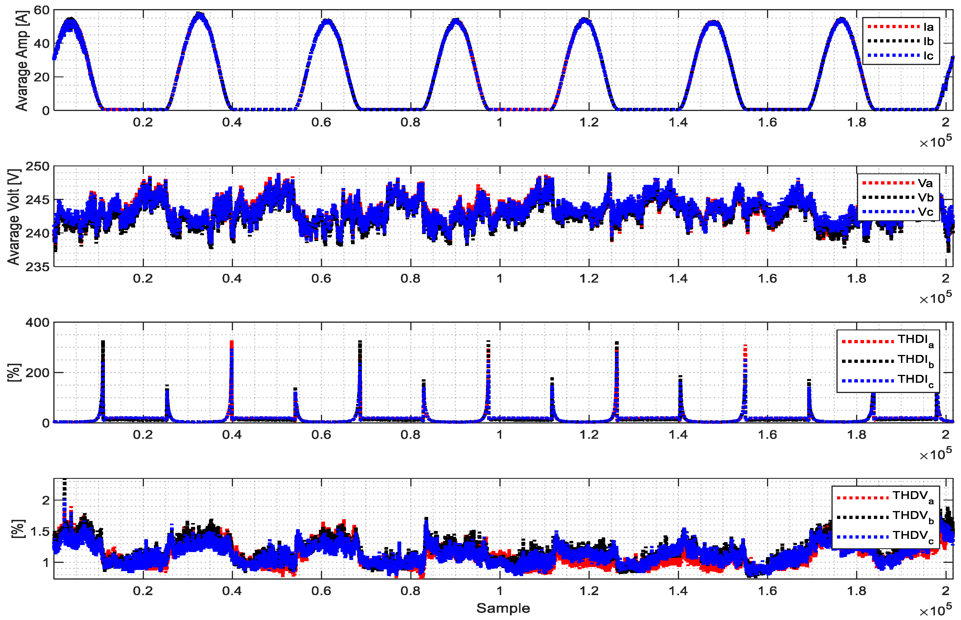
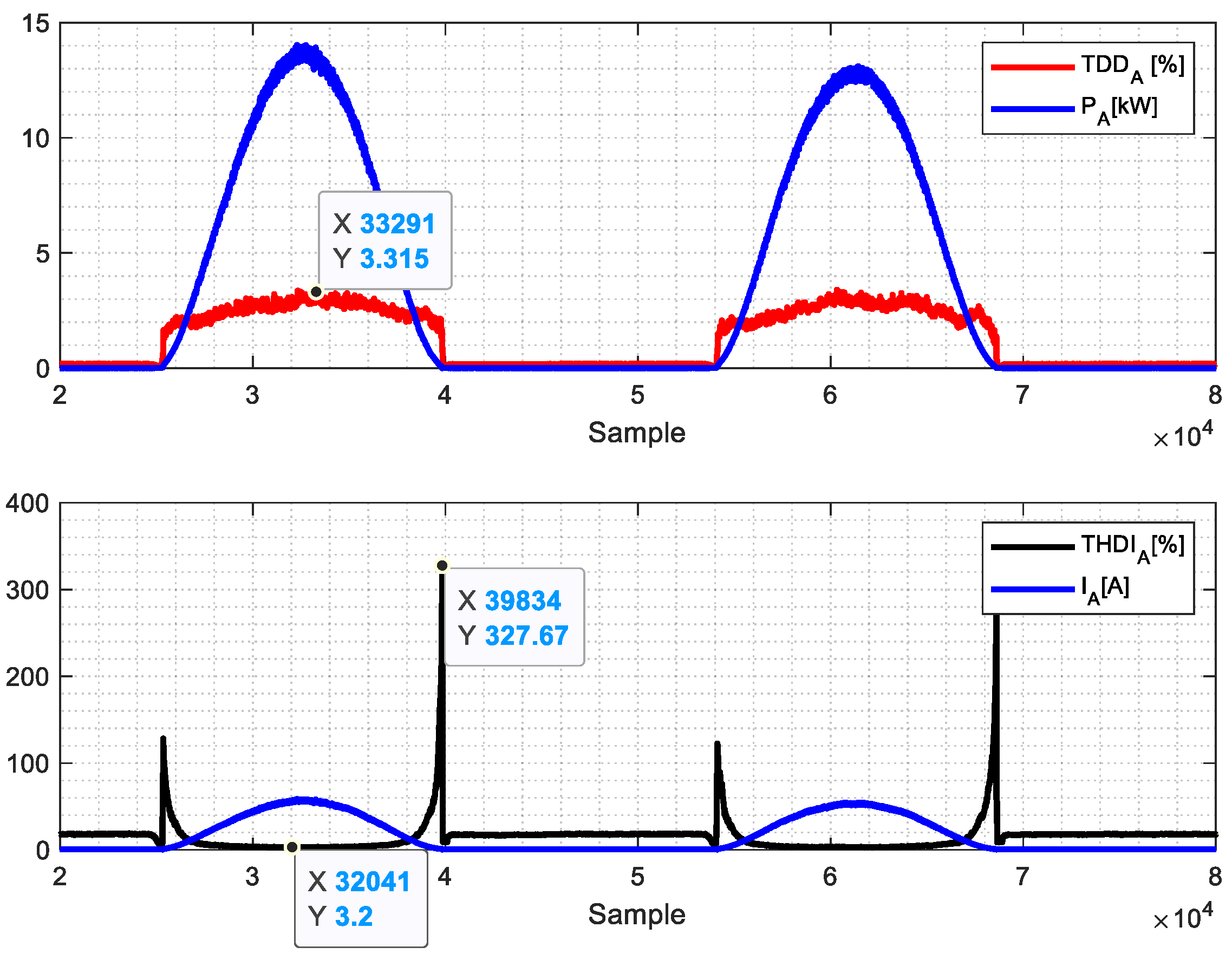
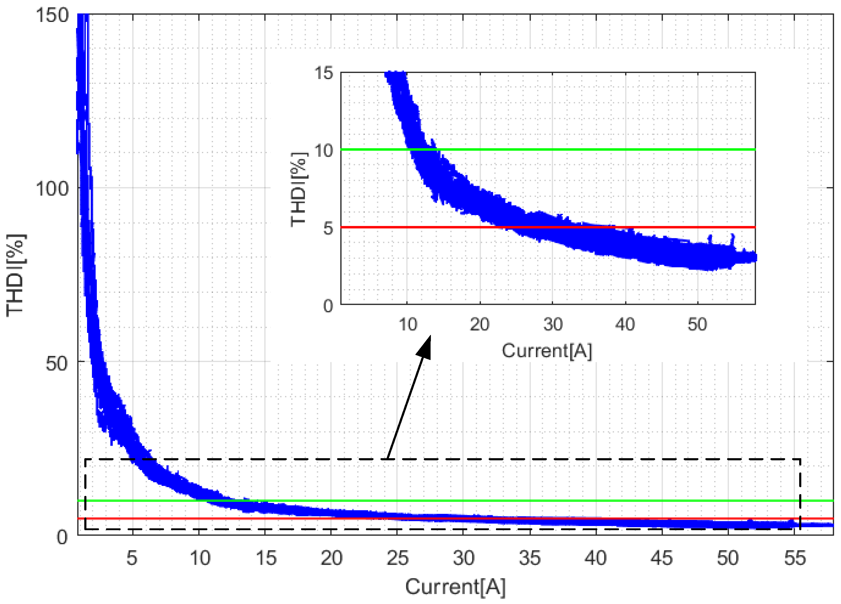
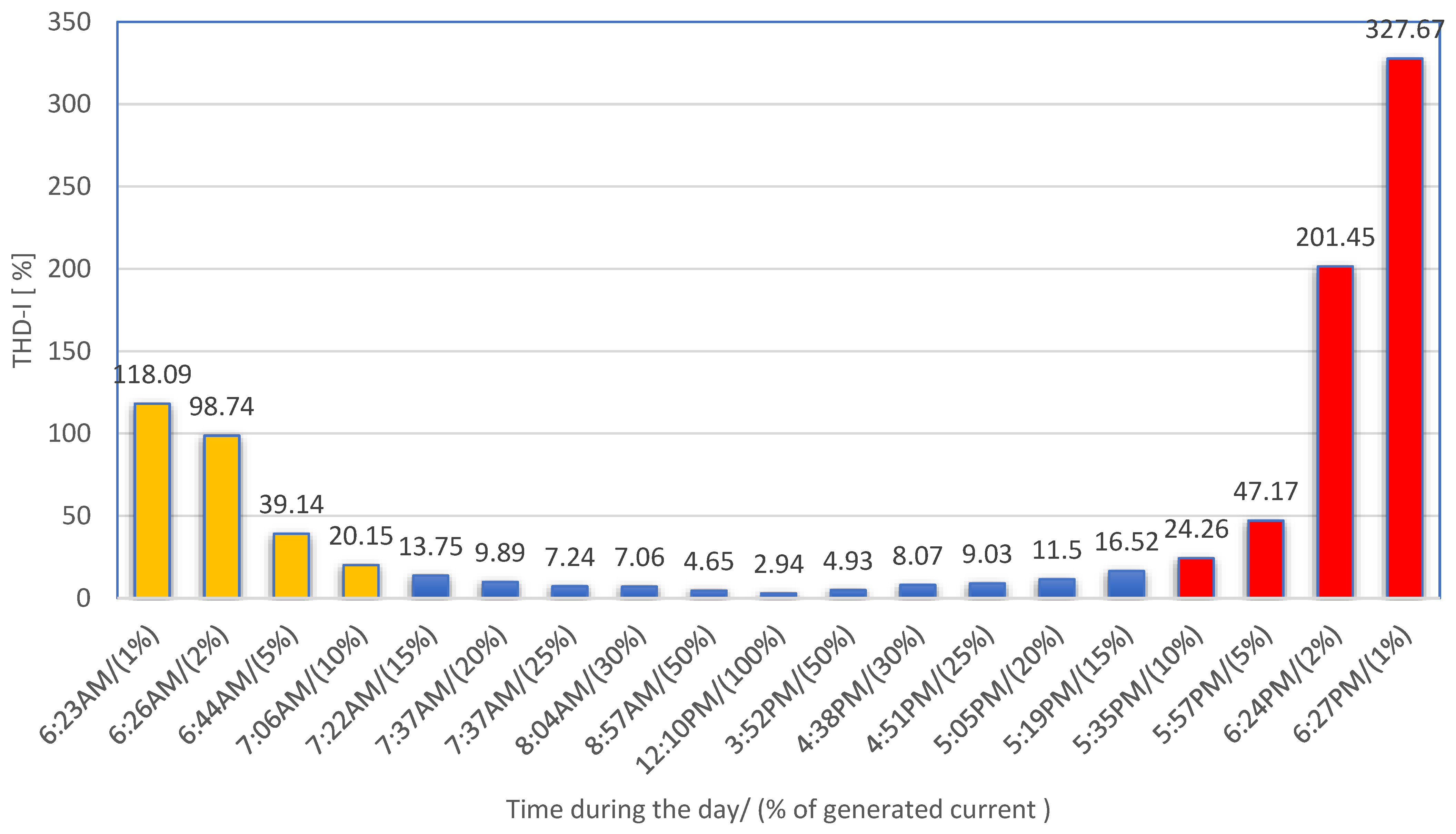
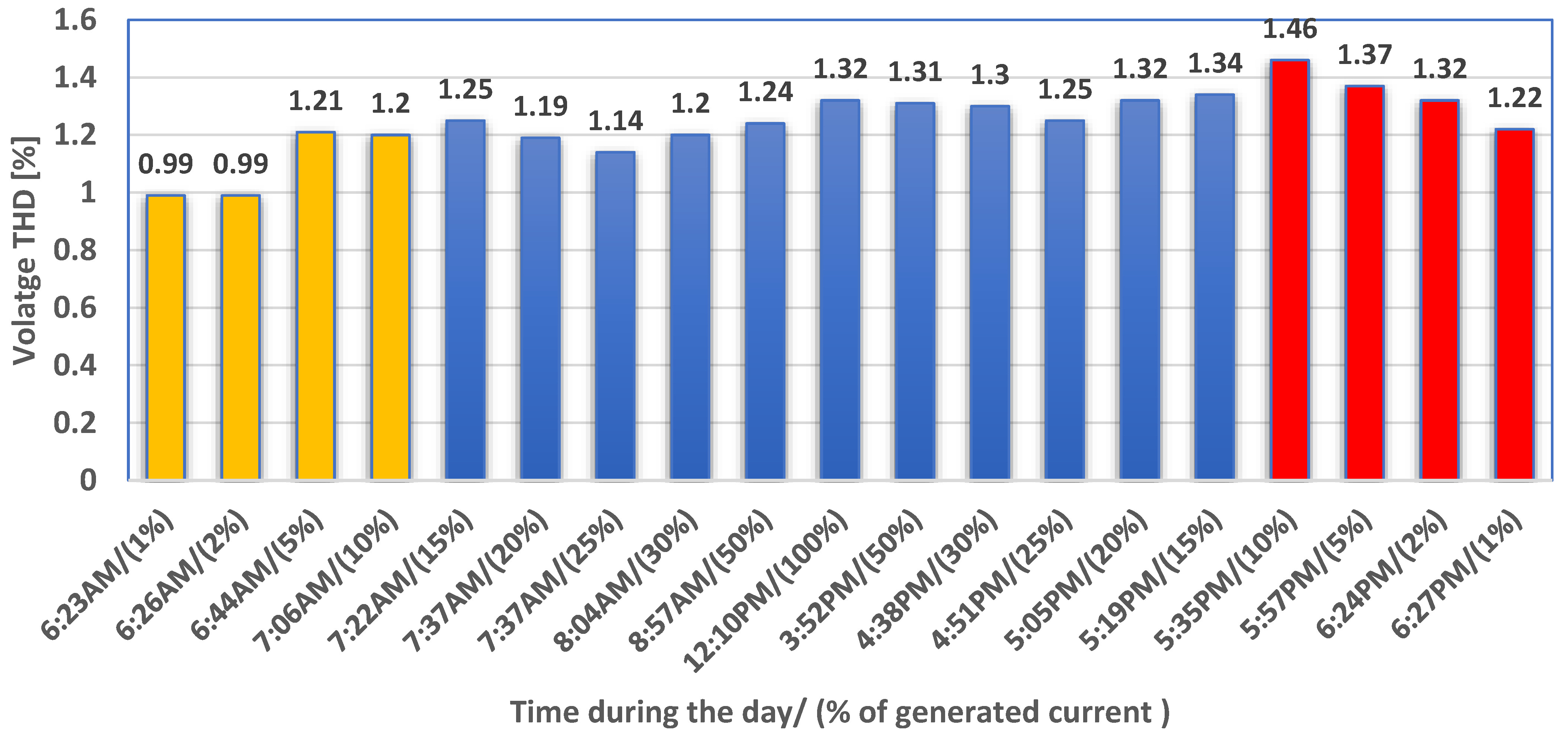
Figure 3 shows the profile of the current, voltage, THDI, and THDV for one week. The THDV variation was between 0.9% and 1.7%, while the THDI had a wider range of values, and thus, TDD analysis was required in this case. Figure 4 shows the zoom for two days. It is observed that TDD showed a steady variation for the generation period with a maximum value of 3.315%. THDI decreased when the PV system generated power but exhibited significant spikes during the transition periods at sunrise and sunset when energy production from the PV started and stopped. Figure 5 shows the variation in THDI with the output current. Analysis revealed that THDI dropped to 10% when the generated power reached 17% and further decreased to 5% at 37% of the generated power. Figure 6 illustrates the variation in THDI at different times of the day, indicating a higher THDI at the beginning and at the end of power generation from the PV inverter (i.e., at sunrise and sunset). The THDI was higher in the afternoon compared to that in the morning and toward sunset compared to sunrise, which is likely due to the grid status and background voltage harmonics. Figure 7 shows the variation in voltage THD at the grid connection point for the same day. It is clearly observed that the voltage THD was higher in the afternoon and at sunset compared to sunrise. As is clearly observed, the THD-I value in the afternoon was higher than that in the morning for the same percentage of generated current. This increase was mainly due to an increase in the grid distribution. Since the inverter controller used grid voltage for its synchronization and feedback control, voltage harmonics impaired control performance, leading to increased current harmonics.

3.2. Monitoring Results and Analysis CIS and UPS

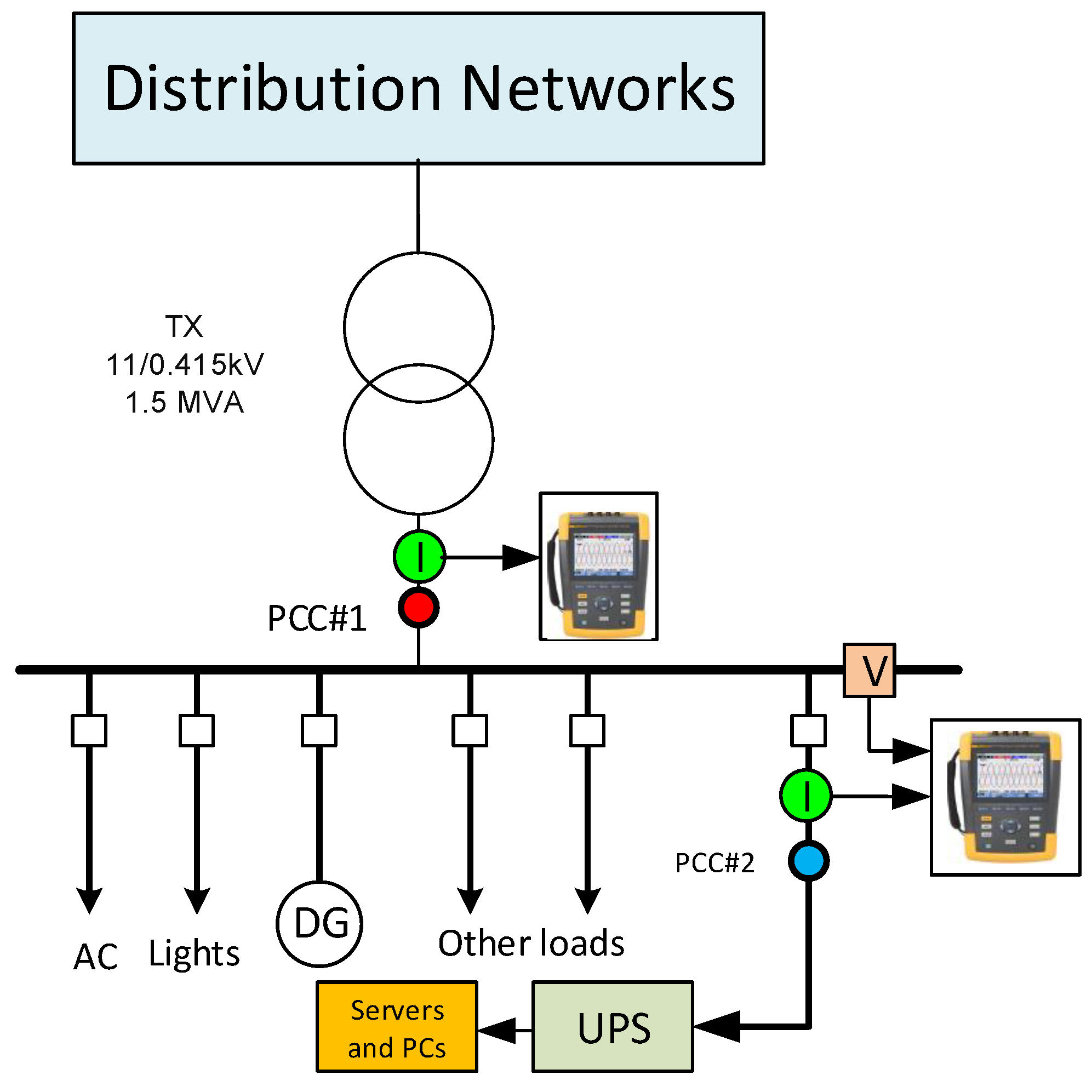
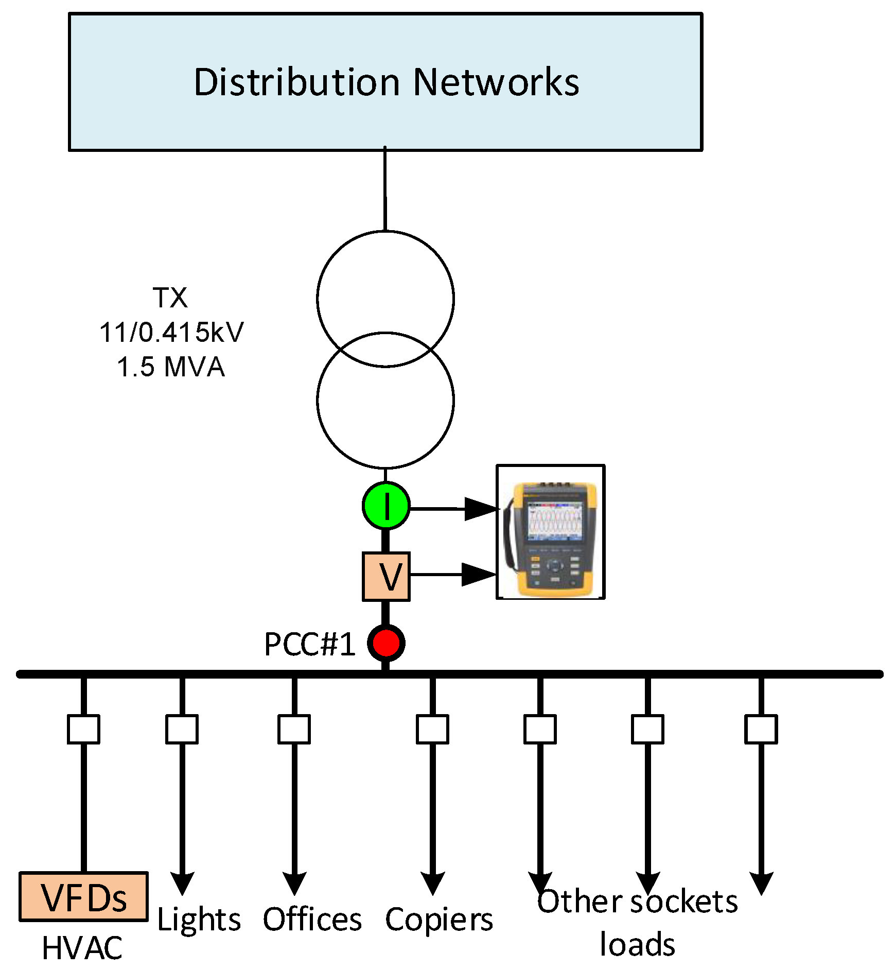
Figure 8 shows an SLD for the electrical system in the Computer Information Center (CIS) at the university. This system consists of an uninterruptible power supply (UPS), lighting loads, air conditioning units (ACs), and other single-phase loads. The system is supported by a standby diesel generator (for emergencies). This site is supplied by an internal 11 kV distribution system within the university through a distribution transformer (11/0.415 kV). The measurements were conducted at two measurement points (PCC#1 and PCC#2), as depicted in Figure 8.

3.2.1. Voltage Profile and Quality at the CIS Bus (PCC#1)

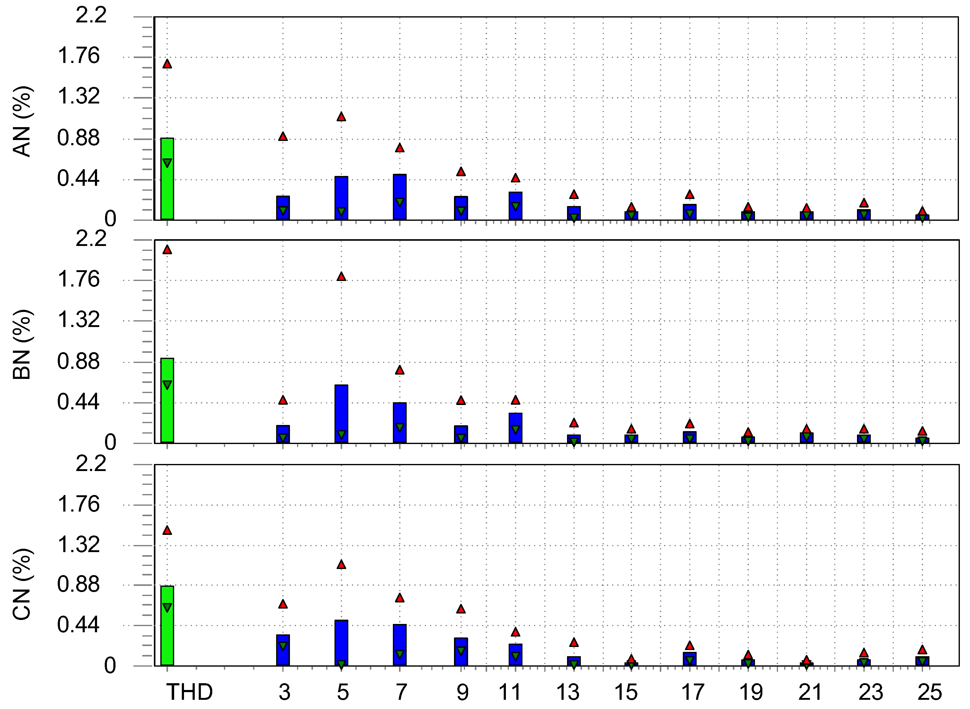
Plots in Figure 9 show the variation in three voltage phases. (The plots show three values: minimum, average, and max.). The voltage varied between 243.5 and 228.71 V, which is within the distribution code of Oman, ±6% of the normal value (240 V) [16]. Figure 10 shows the THD and harmonics voltage contents. The maximum records THDV for the three phases, A, B, and C, are 1.69%, 2.1%, and 1.49%, respectively, with an average value for all phases of 0.88%, which is within the acceptable value based on IEEE519 [15]. The dominant harmonics in all the phases were the 5th and 7th. The THD voltage showed varying values among the phases, which can be attributed to the unbalanced loading between them.

3.2.2. Current Profile and Quality of the UPS System (PCC#2)

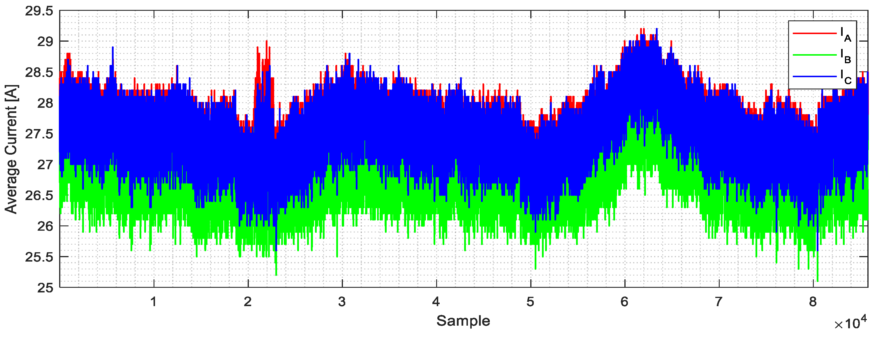
Plots in Figure 11 represent the root mean square average current patterns for the UPS for almost three days. As observed, the current had the same span variation (with min 24 A to max 30 A). This is a typical profile for such a system. The three current phases had some level of unbalance, especially for phase B, but were still within the acceptable limit.
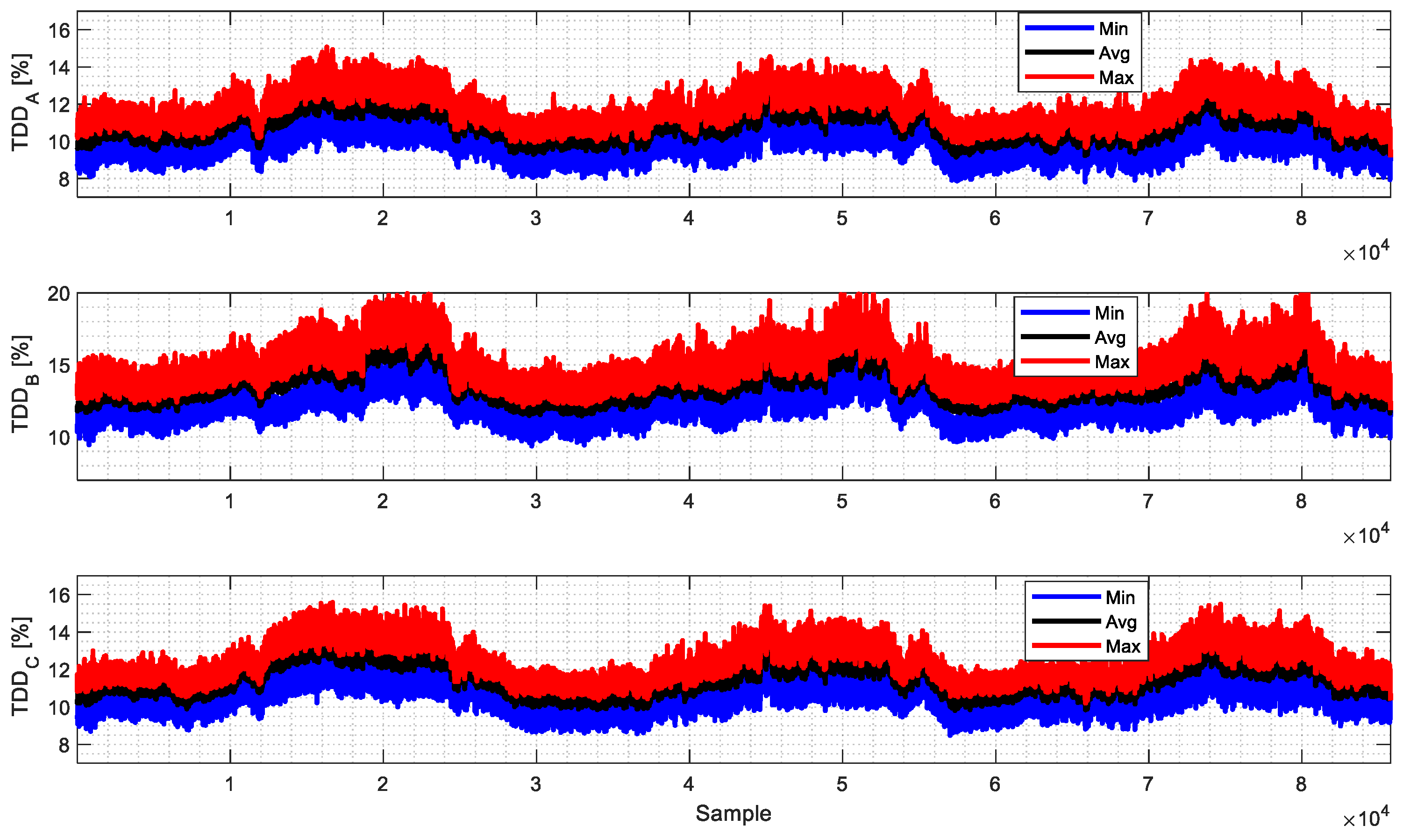
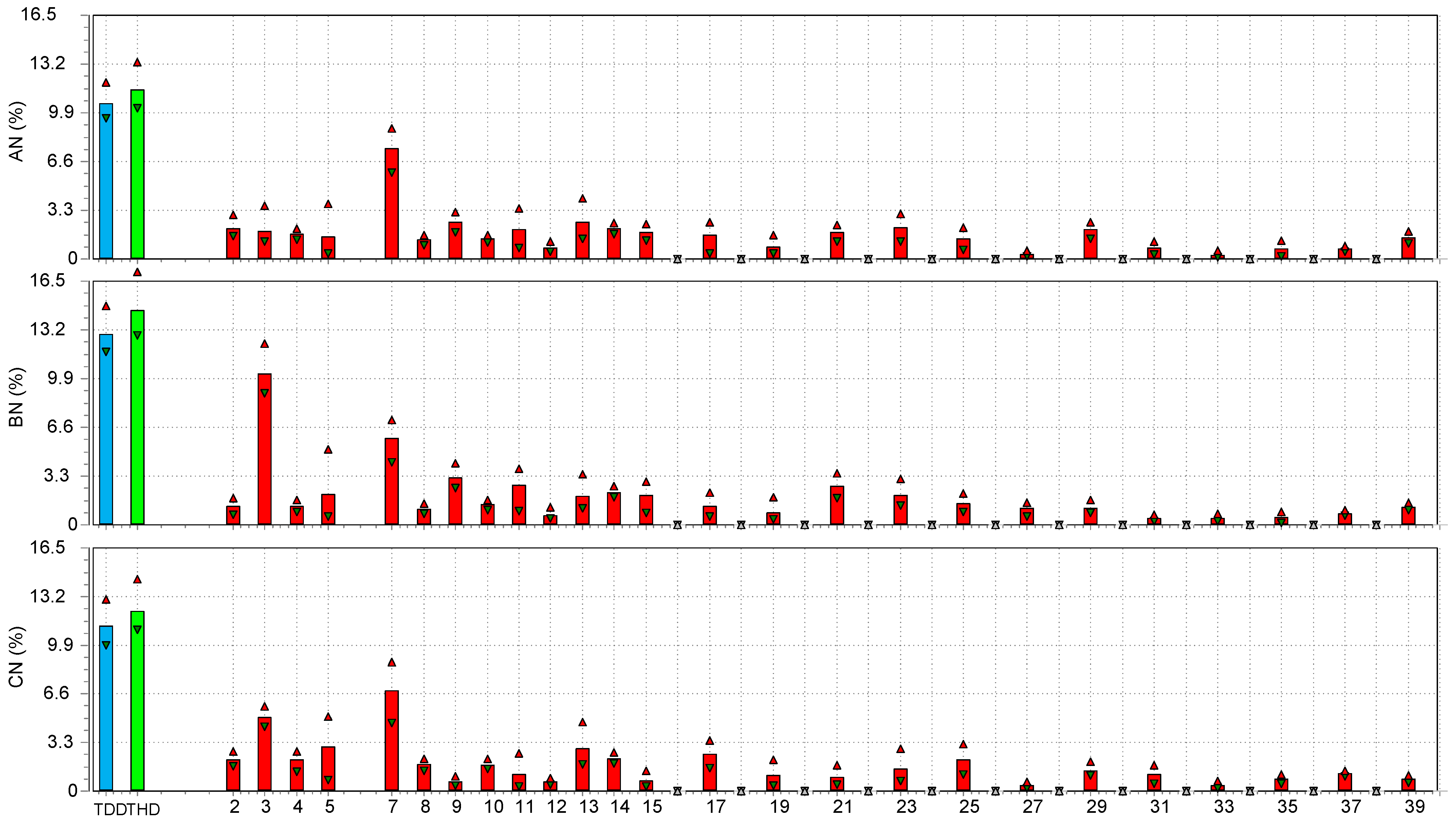
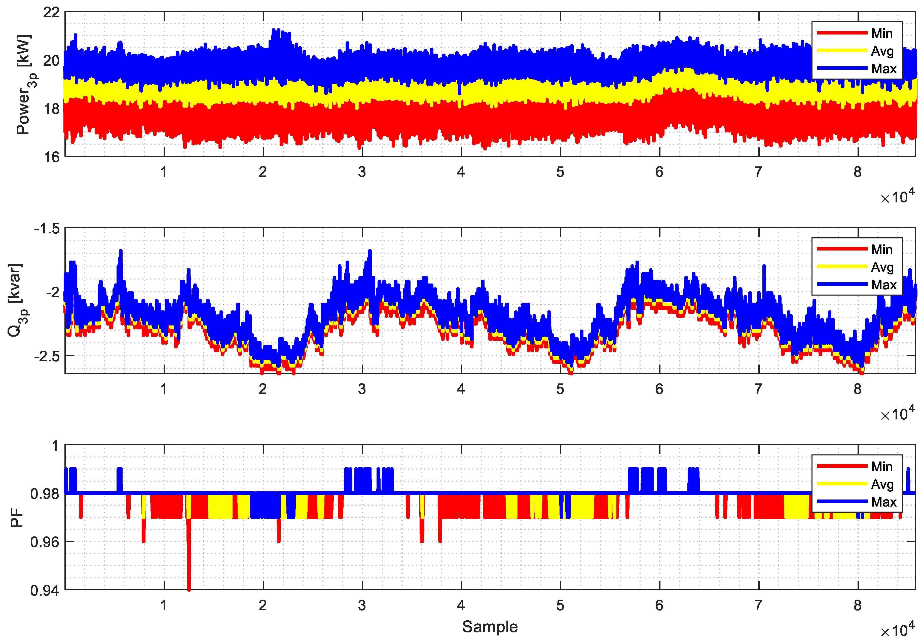
Figure 12 shows the variation in TDD. It is clearly understood that the UPS system exhibited merely a constant harmonics pattern for its complete daily cycles. Figure 13 shows the average TDD, THD, and Harmonics Spectrum for phase currents. The current was highly distorted, and it had odd as well as even harmonics. The dominant harmonics were different between the phases: for phases A and C, it was the 7th, while for phase B, both the 3rd and 7th were dominant. The TDD reached 11.95%, 14.83%, and 13.03% for phases A, B, and C, respectively. Phase B showed higher harmonics current distortion, which explains the increase in voltage distortion, as observed in Figure 13. Figure 14 shows the active, reactive, and power factors consumed by the UPS. The active power varied between 17 and 21 kW, with an average power factor of 0.98. The UPS-injected reverse reactive power varied between −1.8 and −2.8 kvar. This negative var was due to the filter capacitance existing on the front side of the UPS. The maximum registered current was 29 A (as observed in Figure 8). The short circuit level at PCC#1 can be calculated by Isc(pu) = Vpu/Zpu. Zpu is the transformer impedance of 4.5%. Hence, Isc = 1.0/0.045 = 22.22 p.u. (i.e., 2318.7 A). The ratio of Isc/IL was ratio = 2318.7/29 = 80, as per the IEEE519. The TDD limit was 12%, revealing that the TDD was over the limit at PCC#2.

3.2.3. Current Profile and Quality for the Main Incomer (PCC#1)

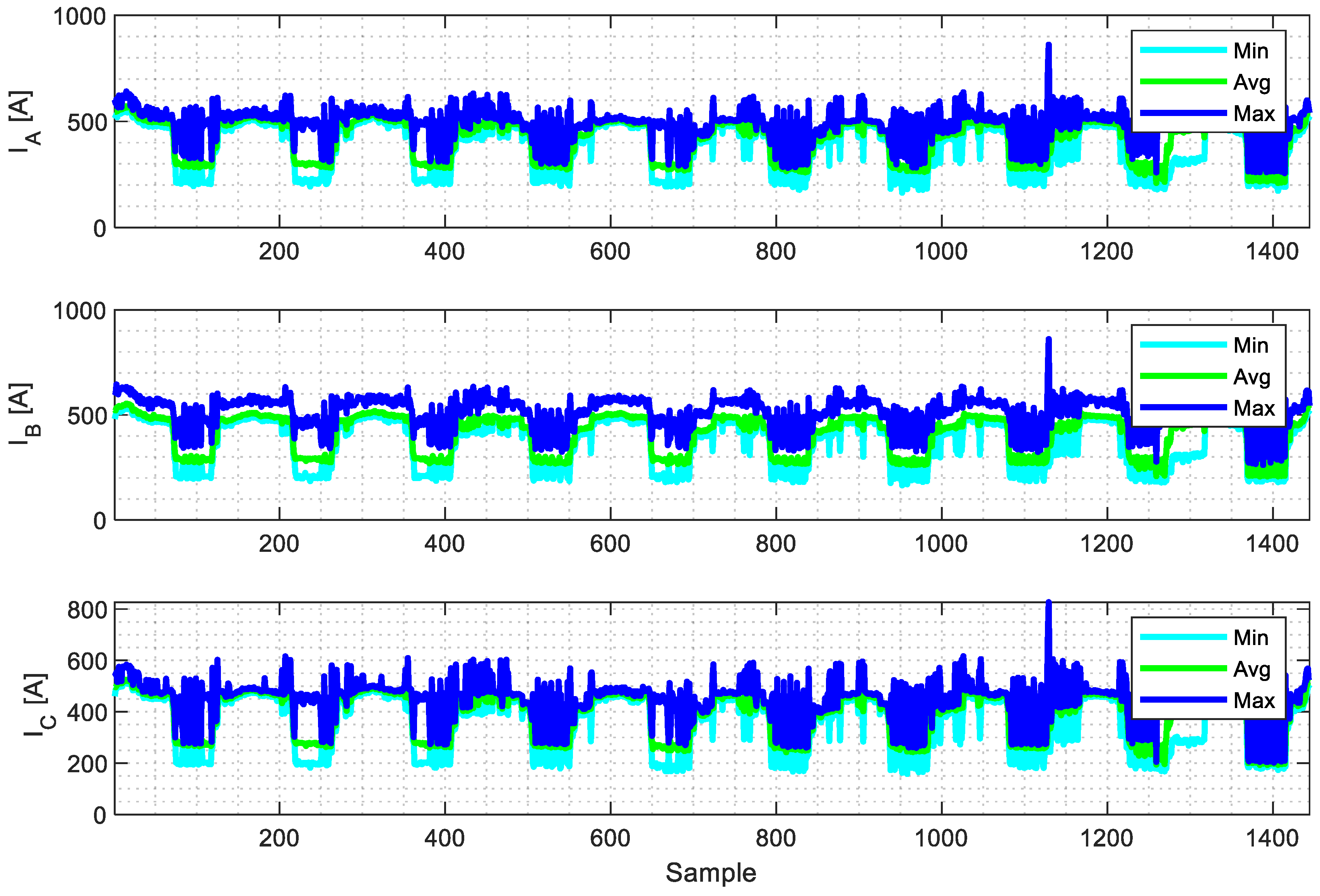
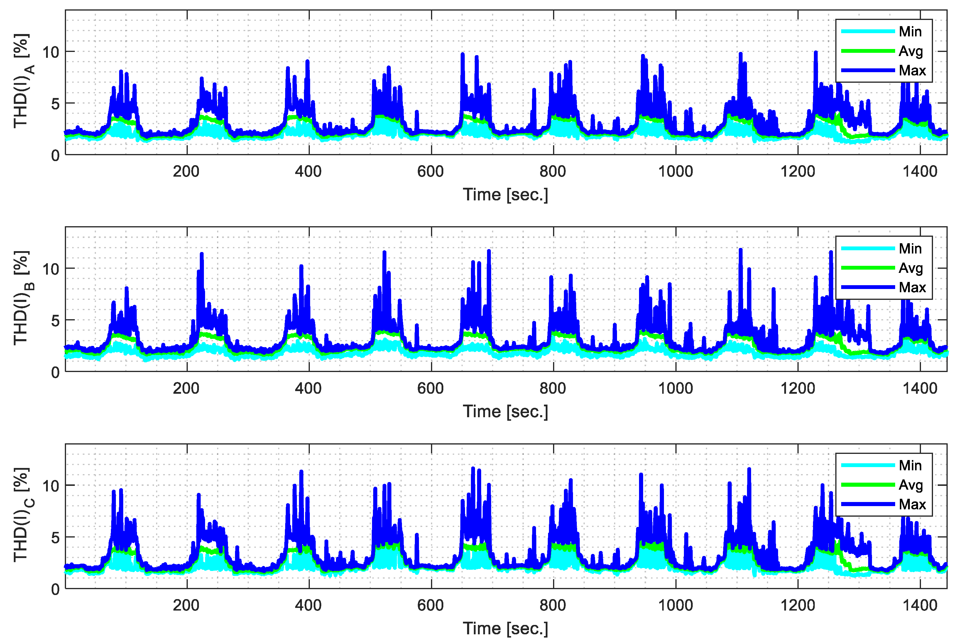
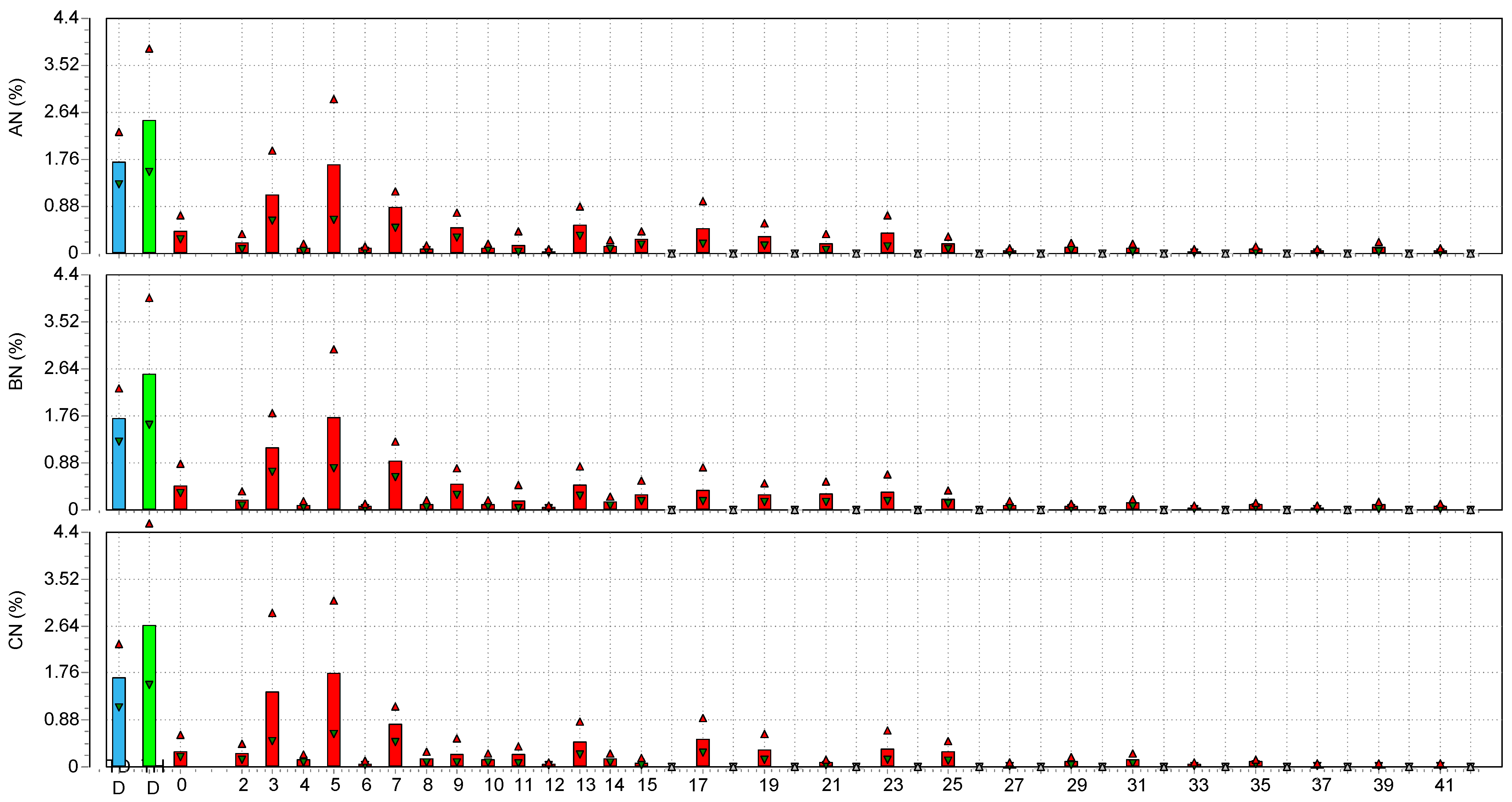
Figure 15 represents the root mean square current patterns during the ten-day test period. The plots show the variation in three values of the phase currents: minimum, average, and maximum, and Figure 16 shows the associated THDI profile. Figure 17 shows TDD, THD, and Harmonics Spectrum for phase currents. At this point, the current was slightly distorted. The level of harmonics at the PCC point was reduced due to harmonics cancelation and increased with linear load compared with no linear load. The TDD reached an average of 2.3% for phases A, B, and C, respectively. The dominant harmonics were the 3rd, 5th, and 7th. According to IEEE519, the TDD level at PCC#1 was within the standard. It is worth mentioning that the distortion created at PCC#1 by the UPS system did not significantly impact the overall TDD at PCC#1. This is attributed to the size of the UPS compared to the overall system size.
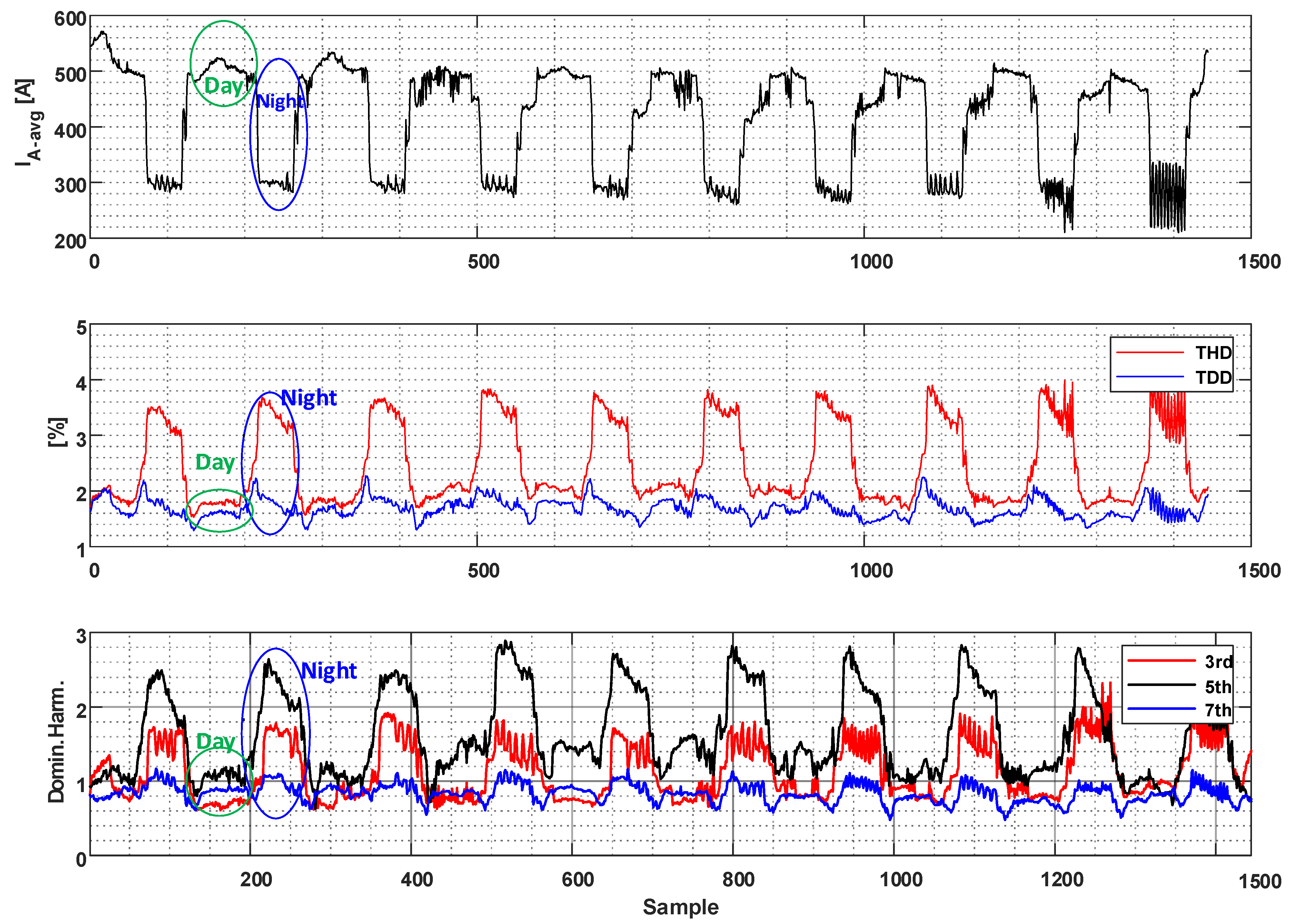
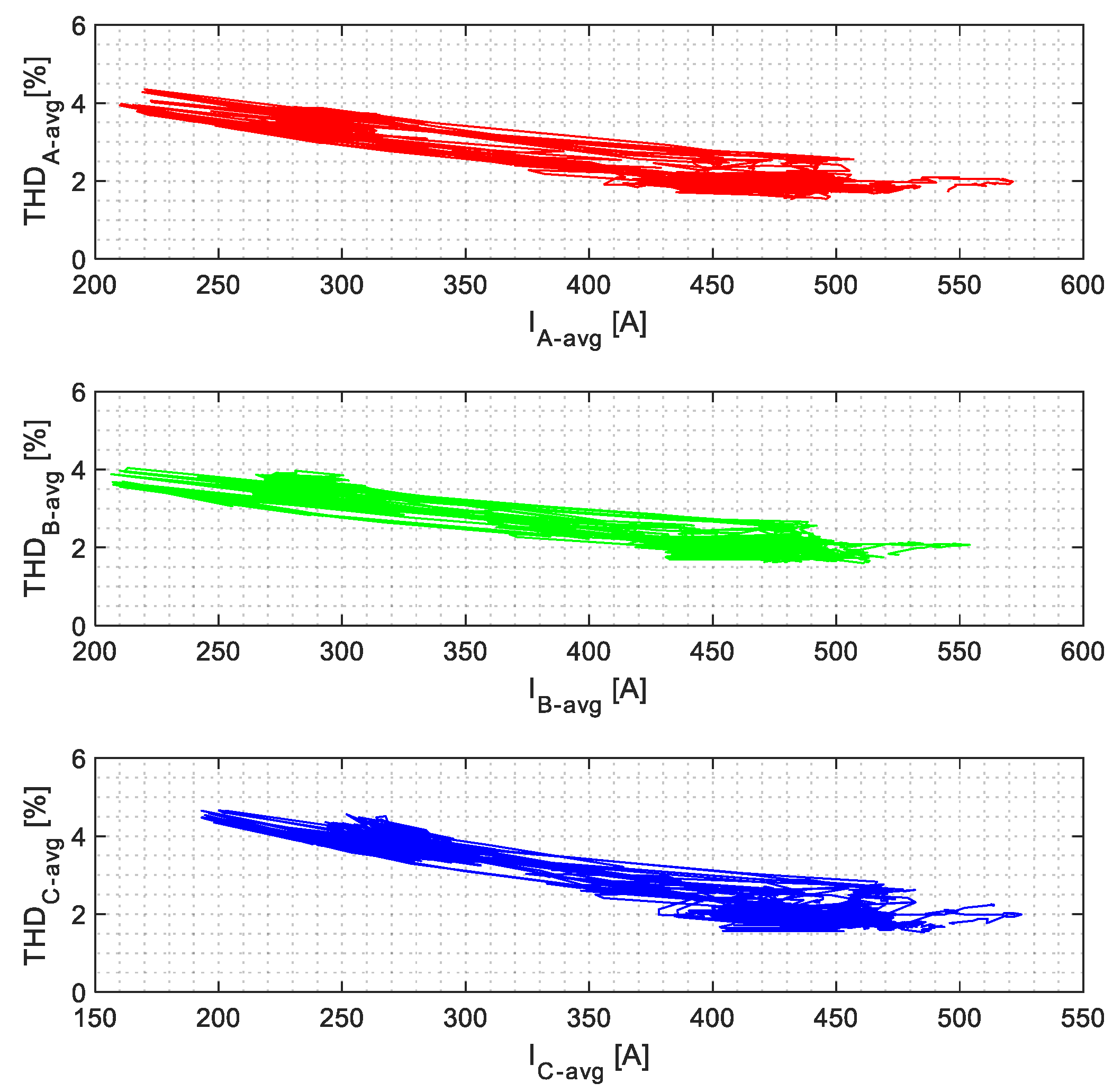
Figure 18 shows the patterns for the selected phase (phase A, other phases showed similar profile), its current, THDI, TDD, and the dominant harmonics. The current indicated two loading levels: a day loading level where the current reached an average of 530 amp and a night loading level with an average value of 250 amp. The harmonic levels increased at night and decreased during the day, as observed in Figure 19. The THD ranged between 2 and 4%, and the dominant harmonic was the fifth. Such a profile can be attributed to the increase in linear loads during the day (mainly AC motors). However, for both operational scenarios, the TDD did not exceed 2.2%.

3.3. Current Profile and Quality for a Motor Drive (Variable Speed Drive, VDF)

Most of the cooling systems on campus are based on a chiller system, where chilled water is circulated among the buildings using motor pumps. These motor pumps were recently upgraded with variable-speed drives (VFDs) to enhance control and efficiency. This subsection shows the measurement and analysis for two types of VFD.

3.3.1. Current Profile and Quality for VFD-I

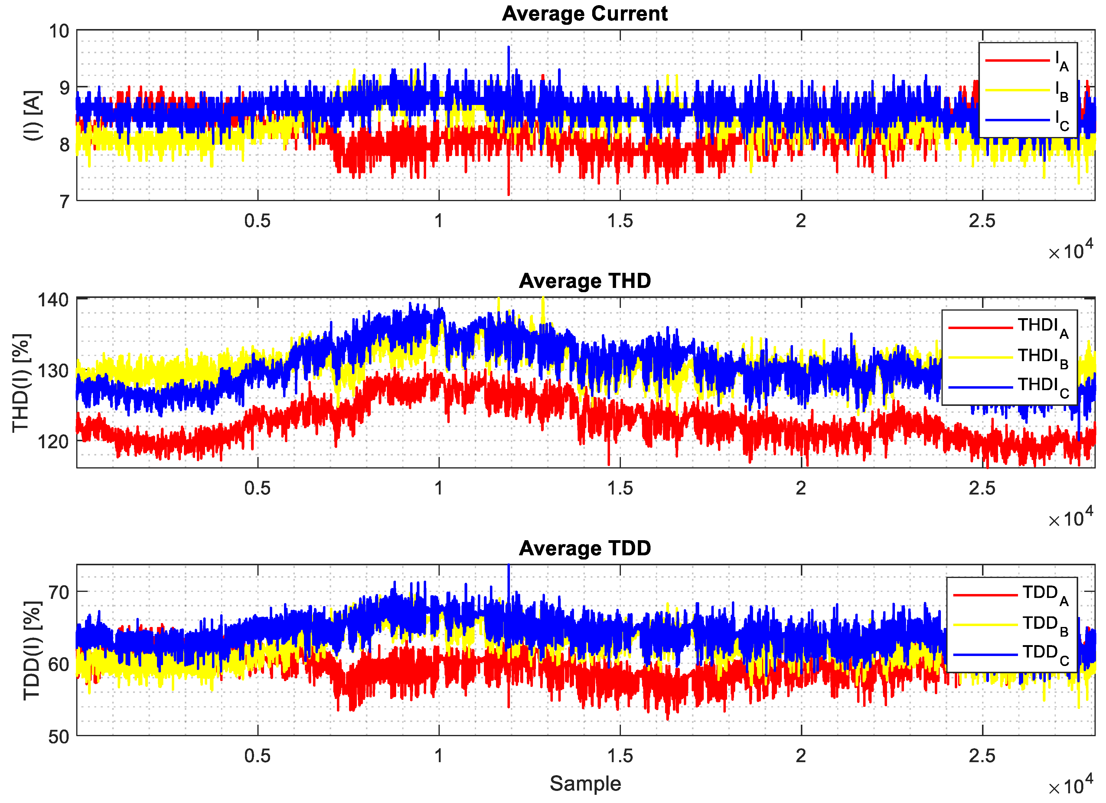
Figure 20 shows the average three phases’ currents, THDIs, and TDDs for the VFD used in the HVAC system (for circulating the cooled water). The measurements were taken for almost 24 h. The currents varied between 7.5 A and 9.0 A. Figure 21 shows a screenshot of the current waveforms, which represent 6-pulses. The current of the phase C was highly distorted. The average value of THDI was 130%, and the average value of TDD was 63%. The dominant harmonics currents were 5th, 7th, 11th, and 13th, as depicted in Figure 22.

3.3.2. Current Profile and Quality for VFD-II

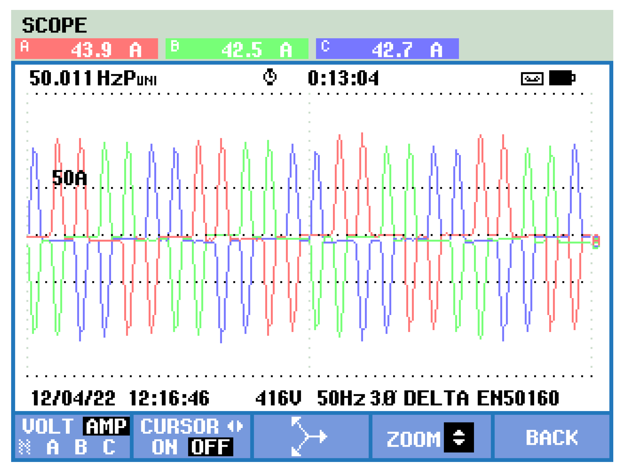
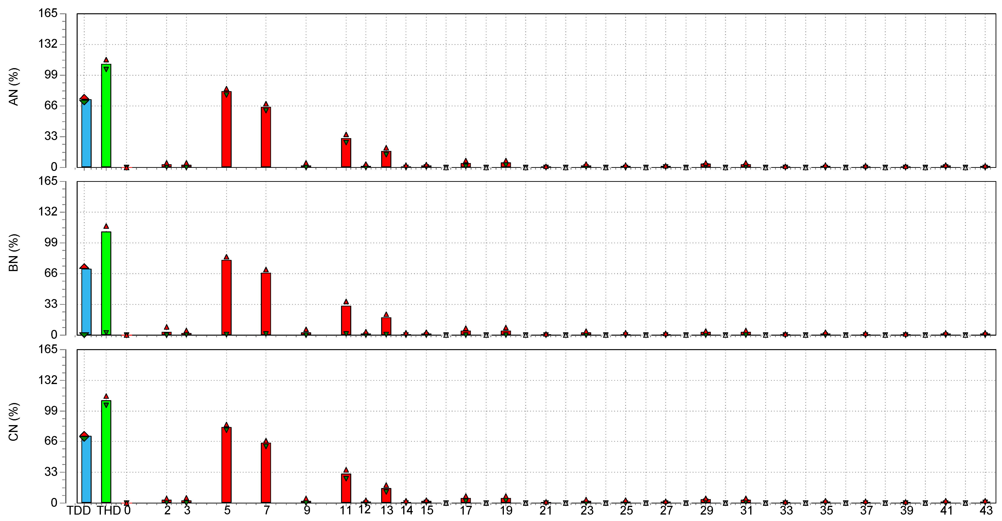
Figure 22 shows the average three phases’ current, THDI, and TDD for the VFD used in the HVAC system (for circulating the cooled water). The currents changed around a value of 43.0 A. Figure 23 shows a screenshot of the current waveforms, which represent 6 pulses operation. The current in phase C was highly distorted. The average value of THDI was 110%, and the average value of TDD was 72%. The dominant harmonics currents were the 5th, 7th, 11th, and 13th, as shown in Figure 24.

3.4. Current Profile and Quality at Engineering Building

A sample from the colleges on the SQU campus was monitored, which was the College of Engineering. Figure 25 shows a single line diagram of the electrical system used in the engineering building. This system consists of an HVAC based on variable frequency drives (VFDs), light loads, and other loads. Figure 26 shows the current, THDI, and TDD measured at the 0.415 kV bus on the LV side of the building transformer. The current showed two levels: a day level that reached 430 A, and a night level dropped to 155 A.

3.5. Current Profile and Quality at Main Substation C

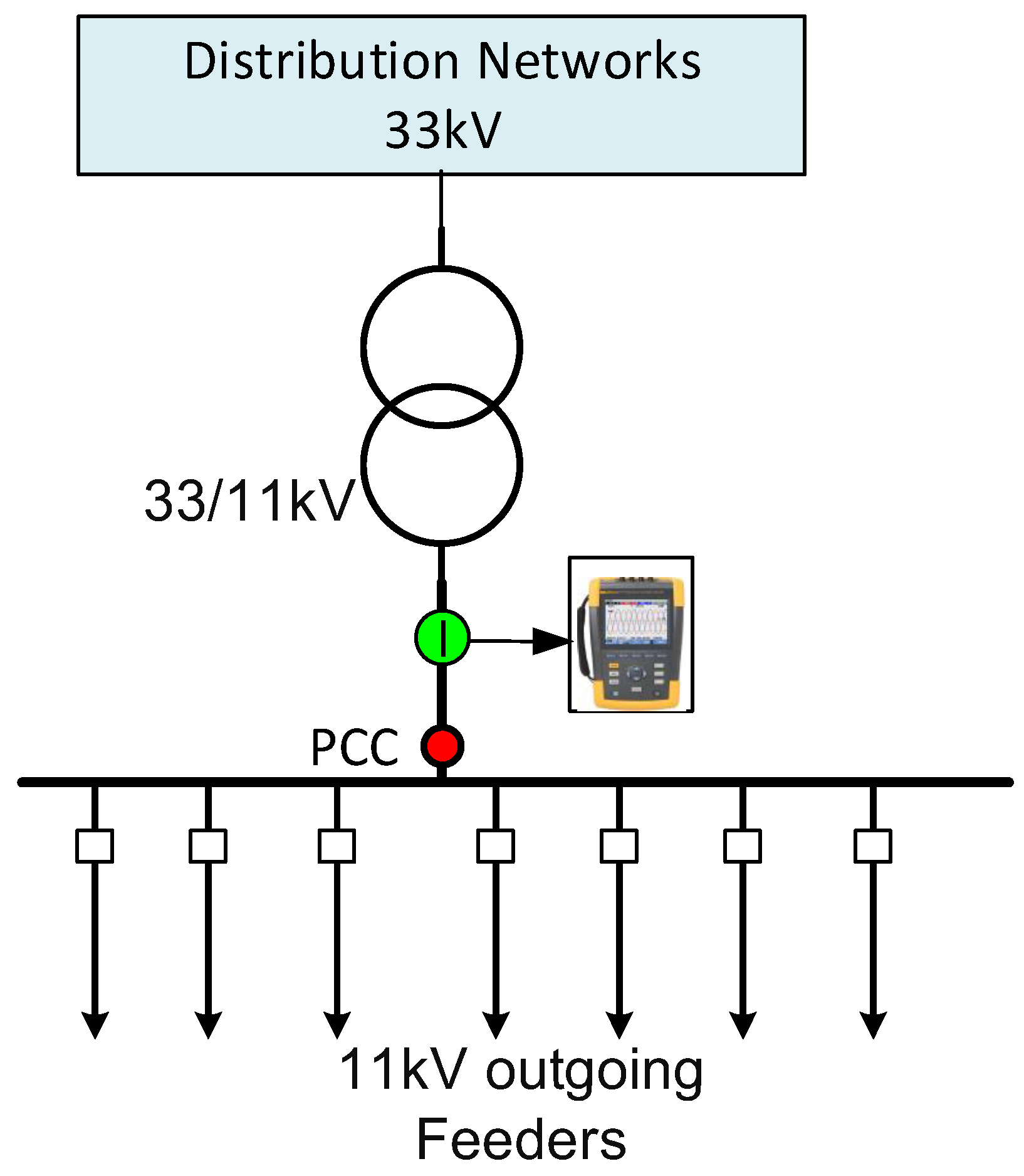
Figure 27 shows a representative SLD for substation C 33/11 kV. The measurements were taken on the 11 kV side of the transformer, as pointed out in the figure. The measurement was limited to current due to the accessibility limitation to the voltage circuit and we observed that there were no issues with voltage harmonics, as the downstream measurement showed that the voltage distortion was below the limit.
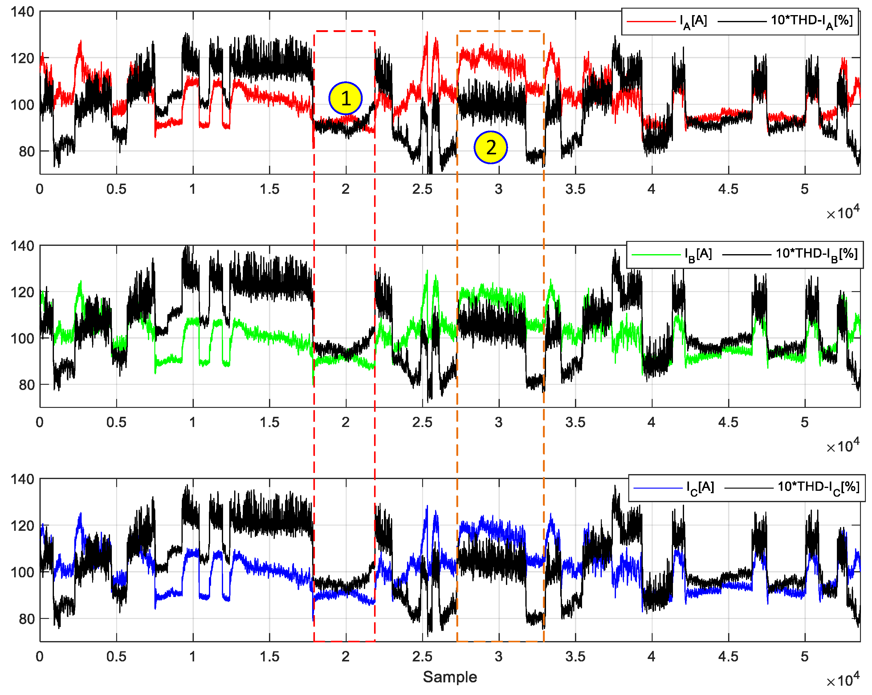
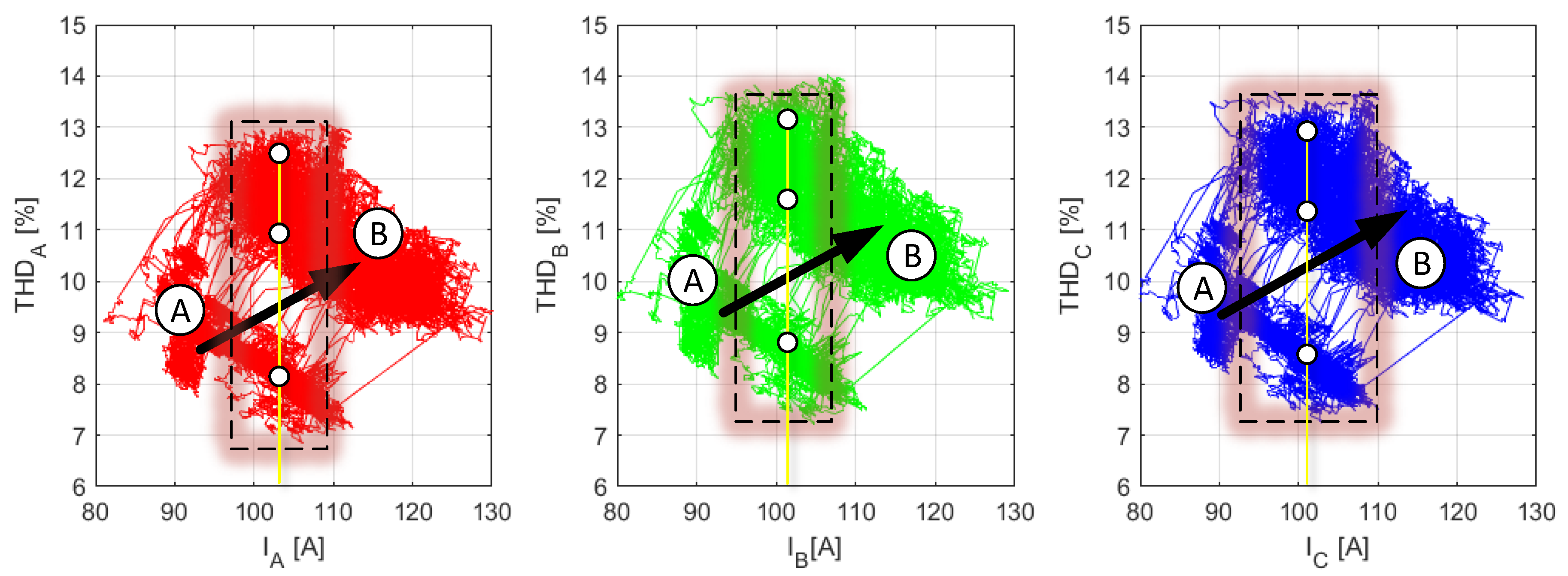
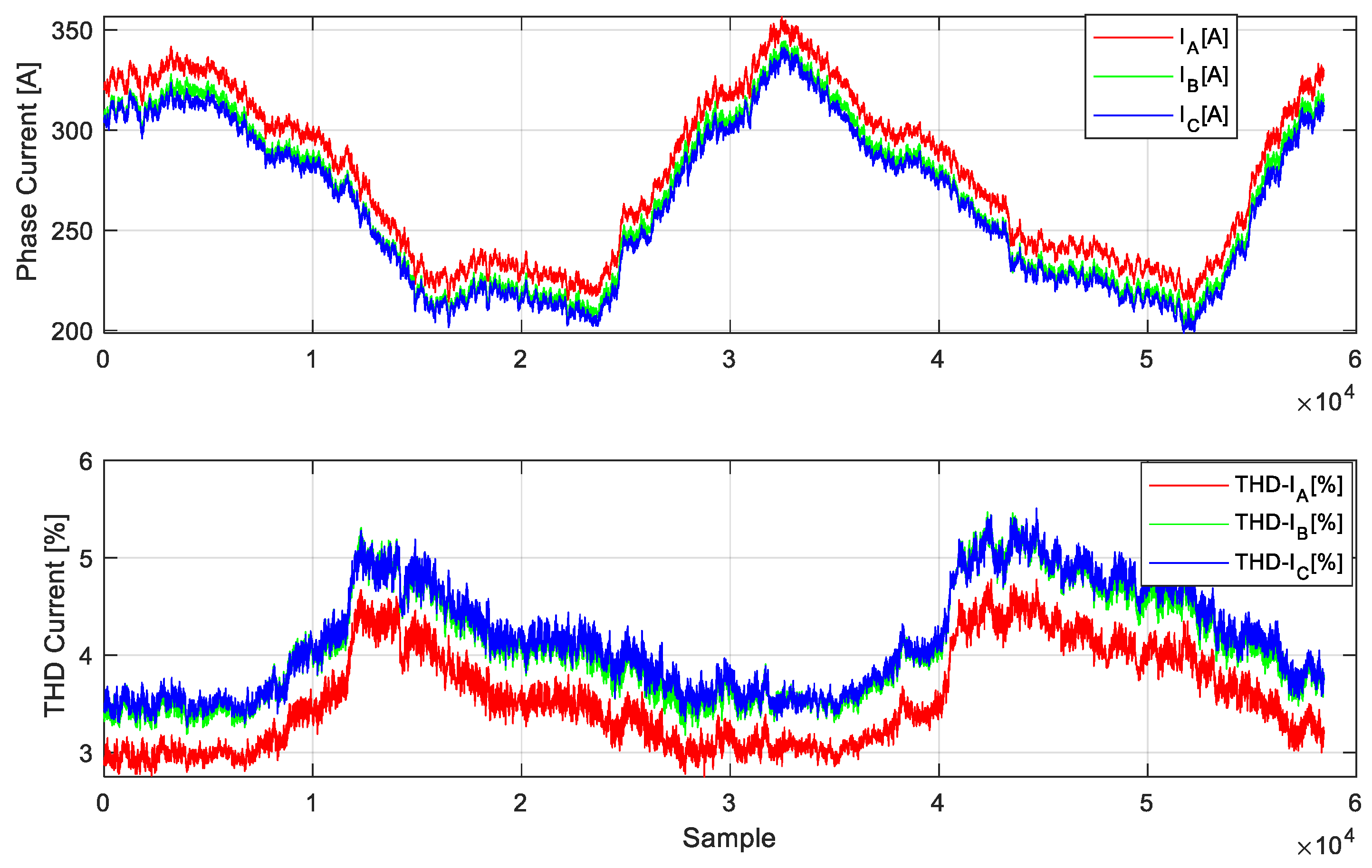
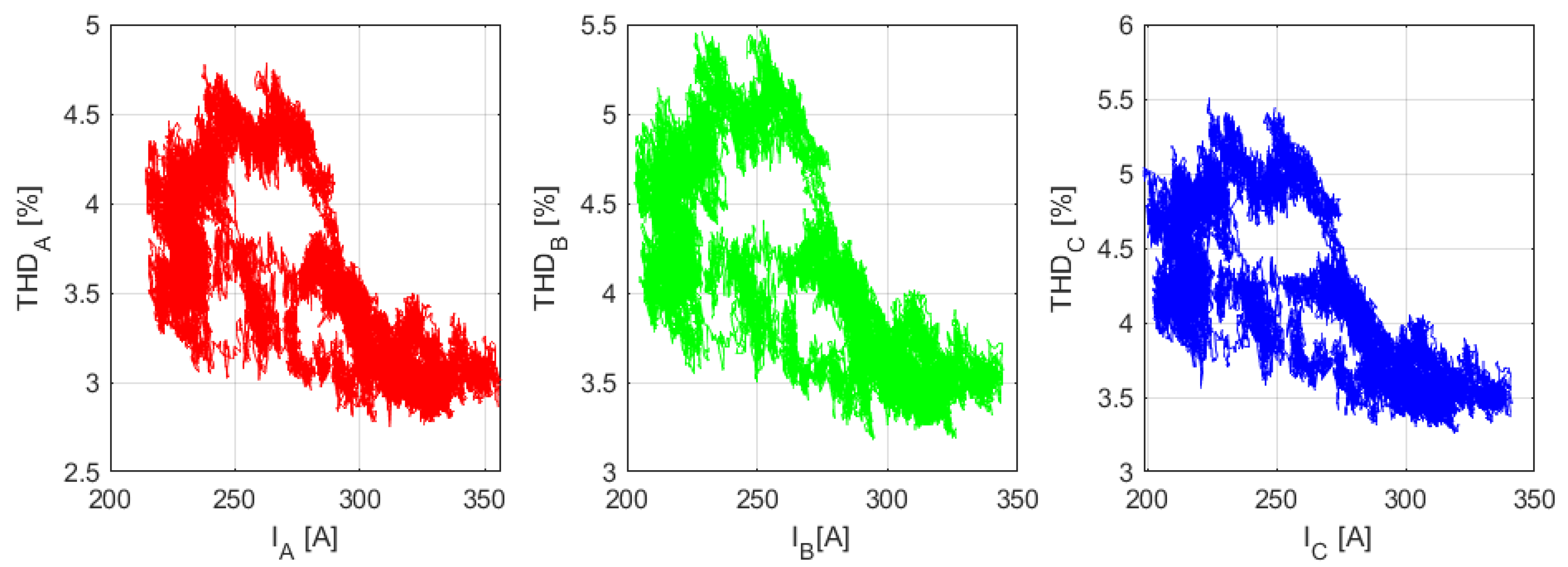
Figure 28 shows the measured phase currents and the THDI at the measured point, indicated in Figure 27, which was the 11 kV incomer side of the main substation C that feeds the university outgoing feeders. From Figure 28, the variation and relationship between the load current level and the THD-I was not consistent over different periods. As depicted in point 1 of Figure 28, the relationship was directly proportional during certain periods. However, in other periods, it was inversely proportional, as shown in point 2. This kind of pattern created two group levels of the THD-I chat, which are shown in Figure 29, which shows THD with respect to the current that flowed in the phases.
It is interesting to note that, for the same load current, there were multiple values for the THD-I, as highlighted by the rectangular area in Figure 29. The THD-I varied from 7% to 14%, depending on the load’s operational mode. When linear loads were switched on, the THD was lower, whereas the addition of nonlinear loads increased the THD. For the transition to a higher current, as seen in Zone 2 of Figure 29, the THD-I point in Figure 29 shifted from Zone A to Zone B. For the same Zones A and B, the THD-I showed a downward trend. This can be explained by the transition to a higher current.
The variation in THD exhibited a unique profile that was highly dependent on the timing of operations. During certain periods, as the current increased, the THD decreased (Period A in the graph), indicating that the added loads were linear. Conversely, in other periods, as the current increased, the THD increased, indicating that the added loads were nonlinear. This behavior was consistent for both low- and high-current operations. However, when transitioning from low- to high-current groups, there was a noticeable increase in THD.
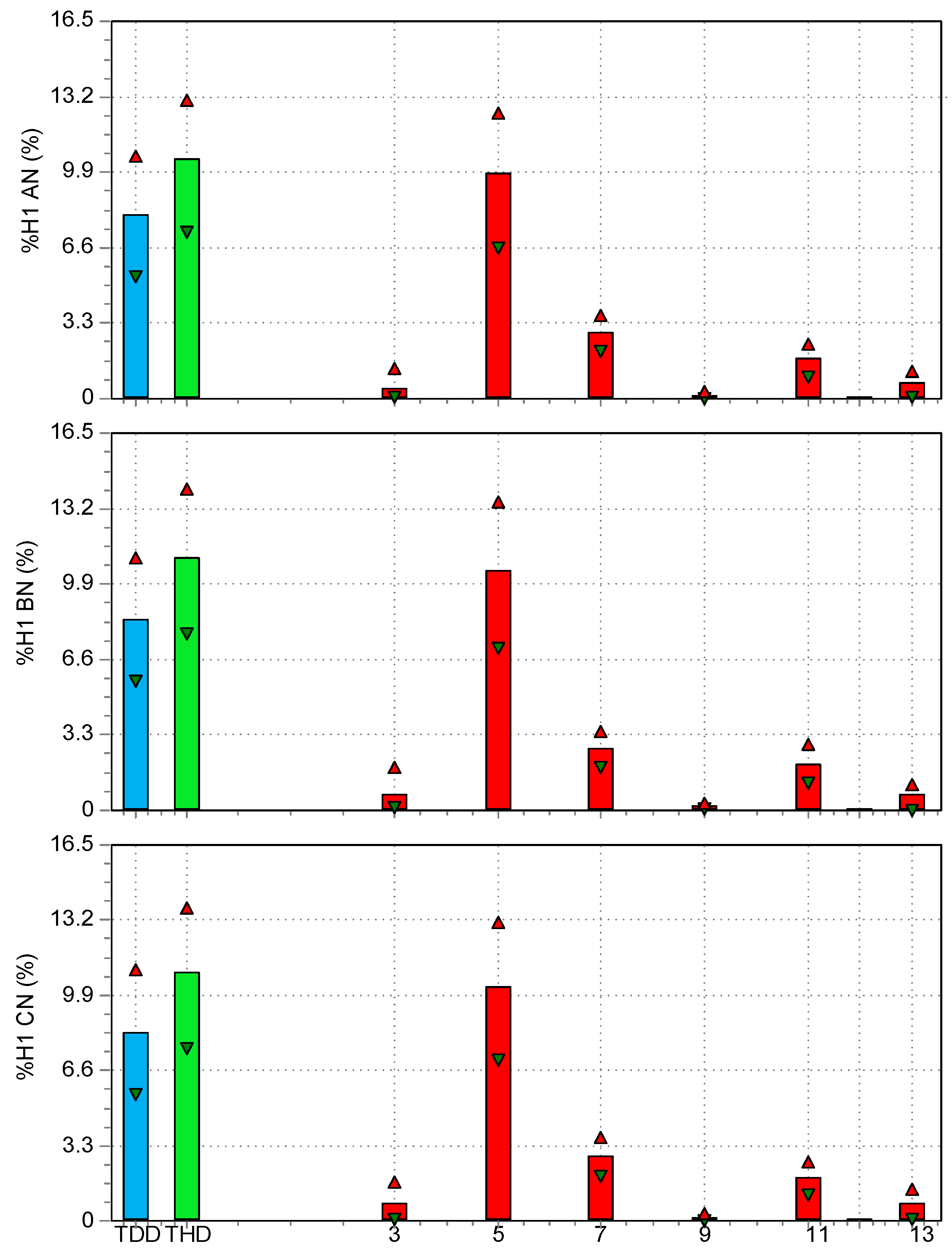
Figure 30 illustrates the TDD, THD, and Harmonics Spectrum for the phase currents of Substation C. The Total Demand Distortion for different phases was similar, whereas the THD for phase A was slightly lower compared with the other phases. The average THD was 10.45%, while the average TDD was 8.35%. The dominant harmonics currents were 5th, 7th, 11th, and 13th, as depicted in the figure.

3.6. Current Profile and Quality at the Main Substation A

SQU has built a new substation, substation A, to meet the new demand associated with an increase in the system capacity and new buildings for the hospital. The new building has been equipped with modern electrical devices, and the majority are power electronics-based devices (LEDs, LCDs, medical equipment, etc.). However, the cooling load was still the majority load, which represented around 70% of these buildings. The measurements were repeated at the main substation A, and an almost similar trend in results was obtained to that of substation C. The load current consumed from this substation was more (almost 300 A) compared with substation C (around 100 A). Figure 31 shows the measured phase currents, and the THD-I measured at the 11 kV bus of the main substation station. Compared with substation C, the levels of THD and TDD were lower at this location. The reduction in THD and TDD was around 60%, and phase A had the lowest distortion for both substations. The loads on the two phases were slightly lower compared with the load on the third phase, as shown in Figure 31. These two phases will have slightly more THDI compared with the third phase. The variation in THD-I across different phases relative to the load current is depicted in Figure 32. Generally, at this site, as the load increased, THD-I decreased. This is because the additional load consisted mostly of linear loads, resulting in a lower THD. There was more variation in phases B and C compared with that of phase A since the load on phase A was compared more with the other phases.
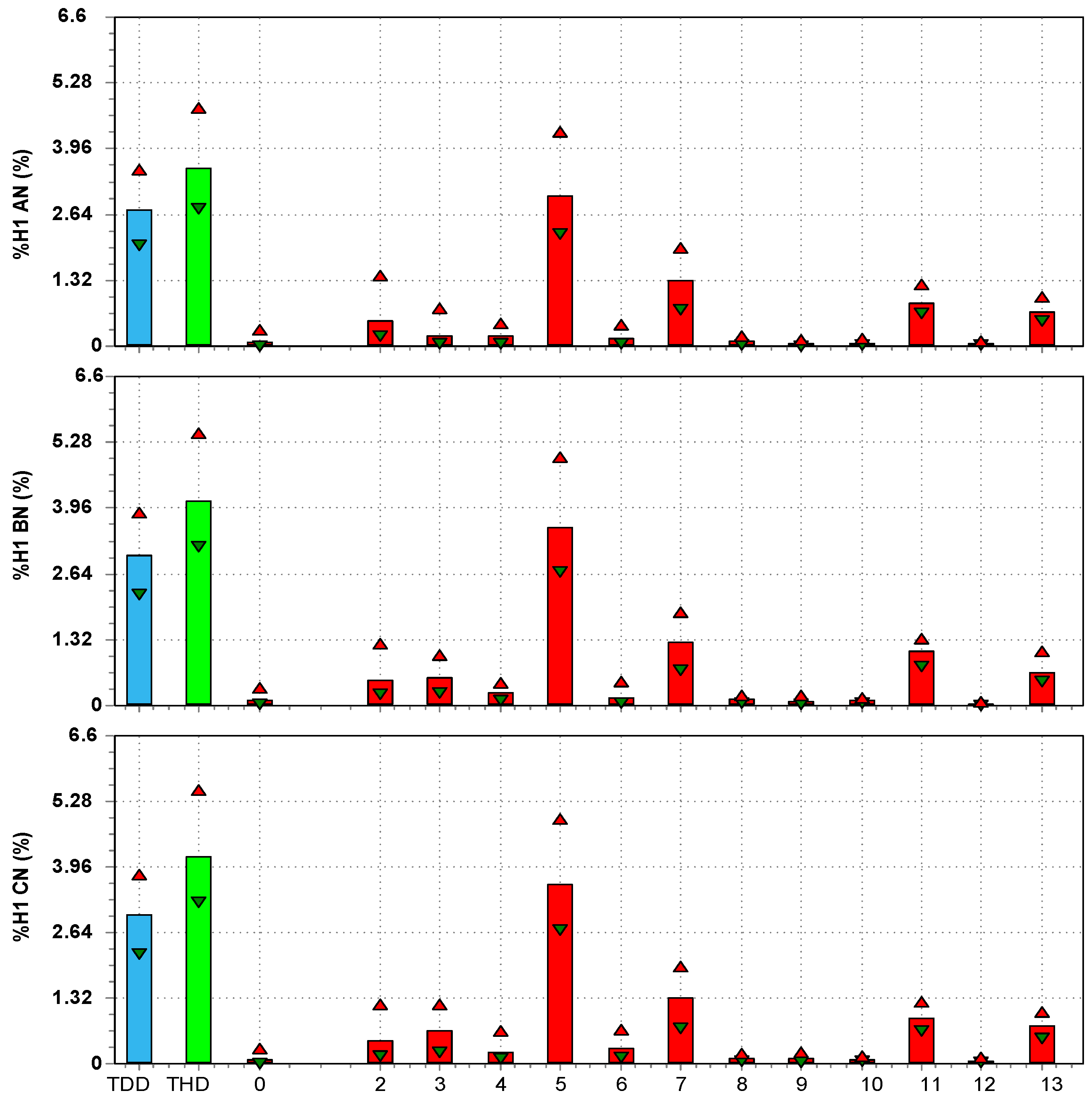
Figure 33 illustrates the TDD, THD, and Harmonics Spectrum for the phase currents of Substation A. The Total Demand Distortion for different phases was identical, whereas the THD for phase A was slightly lower compared with the other phases.
The Total Demand Distortion (TDD) for the different phases was identical, whereas the THD for phase A was slightly lower compared with the other phases. The average THD was 3.96%, while the average TDD was 2.6%. The dominant harmonics currents were the 5th, 7th, 11th, and 13th, as shown in Figure 33.

4. Summary and Conclusions

This paper presented a comprehensive power quality assessment and investigation into the electrical distribution system at Sultan Qaboos University (SQU). Harmonics measurements and analysis were conducted at various locations across the SQU campus, including at the load level (UPS, PV inverters, VFDs), at the 415 V busbar of the distribution transformers level, and at the MV level, 11 kV bus of the main substations. This diverse measurement approach helped to map and quantify the penetration and spread of harmonics at the main point of common coupling (PCC) with the grid and within the university networks. The key findings are
  • The voltage harmonics THDV at all load-side connected points (415 V) exhibited low voltage distortion with a THDV of between 0.9 and 1.7%, within the distribution code and standards;
  • Table 1 summarizes current harmonics THDI and TDD measurement results performed at different locations on the SQU campus, including the 11 kV bus at two substations;
  • The PV inverter system exhibited noticeable current distortion. THDI had higher variations during sunrise/sunset transitions but TDD remained within acceptable limits per the standards;
  • The UPS system showed highly distorted current waveforms with dominant odd and even harmonics. TDD reached 11.95–14.83% and THDI over 100% for some phases. However, at the UPS input (PCC#1), the harmonics attenuated significantly due to cancellations and linear load mixing, reducing TDD to 2.3%;
  • The TDD values at the UPS connection point exceeded the IEEE519 limit. Thus, it is crucial to prioritize the design and implementation of passive filter solutions. Specifically, enhancing the design and configuration of passive filters can effectively mitigate harmonic distortions. This approach involves selecting appropriate filter types and capacities tailored to the specific harmonic frequencies present in the system. Regular monitoring and assessment of filter performance should also be conducted to ensure sustained compliance with regulatory standards and optimal operational efficiency;
  • The VFDs demonstrated extreme current distortion, with THDI over 100% and TDD over 60%, with dominant 5th, 7th, 11th, and 13th harmonics. This is expected for 6-pulse VFDs. A passive filter with proper values is recommended. It is expected that with a passive filter, the THD will reduce to 10%;
  • At both the building and substation levels, current harmonics were noticeable but remained within IEEE 519 limits when accounting for the short circuit current. The Total Harmonic Current Distortion (THDI) ranged from 2 to 10%, and the Total Demand Distortion (TDD) ranged from 2 to 8%, depending on the loading;
  • SQU plans to move toward a green smart system with integrated large-scale PV, upgraded and automated cooling systems, and the replacement of lights with LEDs within the networks. Therefore, the following recommendations are proposed:
    • Conduct regular power quality audits (health checks) and maintenance of equipment to prevent the escalation of harmonic issues;
    • Suppress the harmonics level associated with future expansion and upgrade of the PV system and VFDs by adding filters to the VFD systems and adopting advanced control techniques, such as active front-end converters;
    • Utilizing the isolation transformers with specific winding configurations (e.g., K-factor transformers) designed to handle non-linear loads;
  • The results highlighted the impacts of diverse and aggregate linear loading, with noticeable differentiation between more and less heavily loaded sections of the distribution network. Recommendations are provided for ongoing monitoring and consideration of targeted mitigation efforts to maintain power quality as campus loads modernize and electricity demand increases. The presented methodology and dataset provide a benchmark to guide standards compliance as SQU upgrades aging equipment and expands new high-tech facilities.

Author Contributions

Methodology, K.M.A.; Software, K.M.A.; Formal analysis, A.H.A.-B.; Investigation, K.M.A.; Data curation, K.M.A.; Writing—original draft, K.M.A.; Writing—review & editing, A.H.A.-B.; Visualization, K.M.A.; Supervision, A.H.A.-B.; Project administration, K.M.A.; Resources A.H.A.-B. All authors have read and agreed to the published version of the manuscript.

Funding

This research received no external funding.

Data Availability Statement

The original contributions presented in the study are included in the article, further inquiries can be directed to the corresponding author.

Acknowledgments

The authors gratefully acknowledge the support of Sultan Qaboos University (SQU) in achieving these research outcomes. Special thanks are extended to the staff of the College of Engineering and the Maintenance &Project Department for their invaluable assistance.

Conflicts of Interest

The authors declare no conflict of interest.

References

  1. Singh, B.; Al-Haddad, K.; Chandra, A. A Review of Active Filters for Power Quality Improvement. IEEE Trans. Ind. Electron. 1999, 46, 960–971. [Google Scholar] [CrossRef]
  2. IEEE Standard 519-2022; IEEE Standard for Harmonic Control in Electric Power Systems. IEEE: New York, NY, USA, 2022; pp. 1–31.
  3. IEC 61727; Photovoltaic (PV) Systems—Characteristics of the Utility Interface. International Electrotechnical Commission (IEC): Geneva, Switzerland, 2004.
  4. IEC 61000-3-2; Electromagnetic Compatibility (EMC) Part 3-2: Limits for Harmonic Current Emission (Equipment Input Current <16 A per Phase). International Electrotechnical Commission (IEC): Geneva, Switzerland, 2000.
  5. IEC 61000-3-12; Electromagnetic Compatibility (EMC) Part 3-12: Limits for Harmonic Currents Produced by Equipment Connected to Public Low-Voltage Systems with Input Current <75 A per Phase. International Electrotechnical Commission (IEC): Geneva, Switzerland, 2003.
  6. Kontogiannis, K.P.; Vokas, G.A.; Nanou, S.; Papathanassiou, S. Power Quality Field Measurements on PV Inverters. Int. J. Adv. Res. Electr. Electron. Instrum. Eng. 2013, 2, 11. [Google Scholar]
  7. Alawasa, K.; Al-Odienat, A. Power Quality Investigation of Single Phase Grid-connected Inverter of Photovoltaic System. J. Eng. Technol. Sci. 2019, 51, 597–614. [Google Scholar] [CrossRef]
  8. Khatri, M.; Kumar, A. Experimental Investigation of Harmonics in a Grid-Tied Solar Photovoltaic System. Int. J. Renew. Energy Res. IJRER 2017, 7, 901–907. [Google Scholar]
  9. Alawasa, K. Harmonic distortions and interactions of modern residential electric loads. Int. J. Eng. Technol. 2018, 7, 4174–4181. [Google Scholar]
  10. Alawasa, K.; Al-Mbaideen, A. Power quality assessment and analysis for low voltage distribution networks. Jordan J. Electr. Eng. 2018, 4, 165–175. [Google Scholar]
  11. Mansor, M.A.; Hasan, K.; Othman, M.M.; Noor, M.S.Z.; Musirin, A.I. Construction and Performance Investigation of Three-Phase Solar PV and Battery Energy Storage System Integrated UPQC. IEEE Access 2020, 8, 103511–103538. [Google Scholar] [CrossRef]
  12. Yashomani, Y.; Shyama, K.; Das, P. Experimental Investigation of a Single-Phase UPQC With Minimum VA Loading. IEEE Trans. Power Deliv. 2007, 22, 373–380. [Google Scholar]
  13. Javadi, A.; Hamadi, A.; Woodward, L.; Al-Haddad, K. Experimental Investigation on a Hybrid Series Active Power Compensator to Improve Power Quality of Typical Households. IEEE Trans. Ind. Electron. 2016, 63, 4849–4859. [Google Scholar] [CrossRef]
  14. Hartungi, R.; Jiang, L. Investigation of Power Quality in Health Care Facility. In Proceedings of the International Conference on Renewable Energies and Power Quality (ICREPQ’10), Granada, Spain, 23–25 March 2010. [Google Scholar]
  15. Alawasa, K.M.; AlAbri, R.S.; Al-Hinai, A.S.; Albadi, M.H.; Al-Badi, A.H. Experimental Study on the Effect of Dust Deposition on a Car Park Photovoltaic System with Different Cleaning Cycles. Sustainability 2021, 13, 7636. [Google Scholar] [CrossRef]
  16. Oman Distribution Code. Available online: https://dcrp-oman.com/documents/The%20Distribution%20Code.pdf (accessed on 16 June 2023).
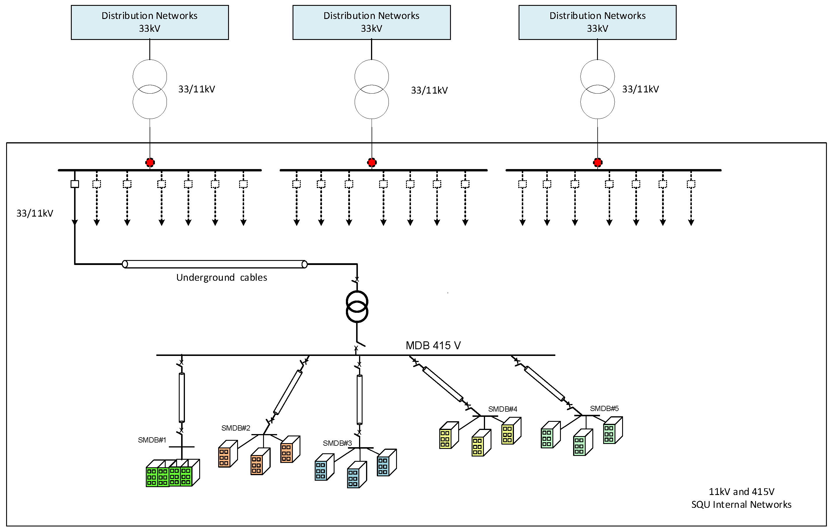
Figure 1. Representative SLD for the SQU 11 kV and 415 V networks.
Energies 17 03998 g001
Figure 2. SLD of the PV-inverter system.
Energies 17 03998 g002
Figure 3. Current, voltage, THDI, and THV of the PV-inverter.
Energies 17 03998 g003
Figure 4. Variation in THDI and TDD over a two-day period varies in current and active power.
Energies 17 03998 g004
Figure 5. Variation in THDI versus the output current.
Energies 17 03998 g005
Figure 6. Variation in the THD-I during the day with respect to the percentage of generated current from the PV system.
Energies 17 03998 g006
Figure 7. Variation in the THD-V at the PCC point at a percentage of generated current from PV system.
Energies 17 03998 g007
Figure 8. Single line diagrams for the CIS system under study.
Energies 17 03998 g008
Figure 9. Voltage profile at the CIS main bus.
Energies 17 03998 g009
Figure 10. THD and Harmonics Spectrum for the phase voltages (Red triangle: maximum value, green triangle: minimum value, blue/green bar: average value).
Energies 17 03998 g010
Figure 11. The three phases’ root mean square average current patterns at PCC#2 (at the UPS connection point).
Energies 17 03998 g011
Figure 12. Variation in TDD against load current.
Energies 17 03998 g012
Figure 13. TDD, THD, and Harmonics Spectrum for the phase currents (Red triangle: maximum value, green triangle: minimum value, blue/red/green bar: average value).
Energies 17 03998 g013
Figure 14. Active, reactive, and power factor for the UPS.
Energies 17 03998 g014
Figure 15. The three phases’ current profiles during the test period.
Energies 17 03998 g015
Figure 16. The three phases’ THD current profiles during the test period.
Energies 17 03998 g016
Figure 17. TDD, THD, and Harmonics Spectrum for the phase currents. (Red triangle: maximum value, green triangle: minimum value, blue/green/red bar: average value).
Energies 17 03998 g017
Figure 18. Phase current, TDD, THD, and Harmonics Spectrum for phase A.
Energies 17 03998 g018
Figure 19. Variation in THD against load current.
Energies 17 03998 g019
Figure 20. Patterns for the three phases’ current, TDD, THD for VFD-1.
Energies 17 03998 g020
Figure 21. TDD, THD, and Harmonics Spectrum for the phase currents of VFD-I. (Red triangle: maximum value, green triangle: minimum value, blue/green/red bar: average value).
Energies 17 03998 g021
Figure 22. Patterns for the three phases’ current, TDD, THD for VFD-II.
Energies 17 03998 g022
Figure 23. Screenshot of the three phases’ waveforms for VFD-II.
Energies 17 03998 g023
Figure 24. TDD, THD, and Harmonics Spectrum for phase currents of VFD-2. (Red triangle: maximum value, green triangle: minimum value, blue/green/red bar: average value).
Energies 17 03998 g024
Figure 25. Single line diagrams for the engineering building system.
Energies 17 03998 g025
Figure 26. The three phases’ current, TDD, THD.
Energies 17 03998 g026
Figure 27. Representative SLD for Substation C.
Energies 17 03998 g027
Figure 28. The three phases’ currents and their THDs patterns at Substation C.
Energies 17 03998 g028
Figure 29. Variation in Total Harmonic Distortion (THD) for the different phases with respect to the current that flowed in the phases at Substation C.
Energies 17 03998 g029
Figure 30. TDD, THD, and Harmonics Spectrum for the phase currents of Sub C. (Red triangle: maximum value, green triangle: minimum value, red/blue/green bar: average value).
Energies 17 03998 g030
Figure 31. The three phases’ currents and the THD for the different phase currents at Substation A.
Energies 17 03998 g031
Figure 32. Variation in Total Harmonic Distortion (THD) for the different phases versus the phases current at Substation A.
Energies 17 03998 g032
Figure 33. TDD, THD, and Harmonics Spectrum for the phase currents of Substation A. (Red triangle: maximum value, green triangle: minimum value, blue/green/red bar: average value).
Energies 17 03998 g033
Table 1. Measurement results.
Type of SystemTHD-ITDD
PV Inverter system2.94–327.67%3.315%
UPSExceed 100%11.95–14.83%
VFD-1-HVAC130%63%
VFD-2-HVAC110%72%
Engineering Building 3–10%3–7%
Main Substation C9.9%7.4%
Main Substation A3.9%2.6%
Disclaimer/Publisher’s Note: The statements, opinions and data contained in all publications are solely those of the individual author(s) and contributor(s) and not of MDPI and/or the editor(s). MDPI and/or the editor(s) disclaim responsibility for any injury to people or property resulting from any ideas, methods, instructions or products referred to in the content.