Article

Life Cycle Assessment of Piezoelectric Devices Implemented in Wind Turbine Condition Monitoring Systems

1
Roberval, Centre de Recherche Royallieu, Université de Technologie de Compiègne, CS 60319, 60203 Compiègne, France
2
Avenues, Centre Pierre Guillaumat, Université de Technologie de Compiègne, 60203 Compiègne, France
*
Author to whom correspondence should be addressed.
Energies 2024, 17(16), 3928; https://doi.org/10.3390/en17163928
Submission received: 3 July 2024 / Revised: 31 July 2024 / Accepted: 2 August 2024 / Published: 8 August 2024

Abstract

:
Assessing the vibration signature produced by a rotating component of the wind turbine enables the identification of operational conditions and the detection of potential faults at an early stage. The main purpose is to enhance the sustainability of wind turbines while increasing the lifespan and uptime of their operational systems. This vibration analysis is based on the processing of the signal provided by sensors, which often incorporates piezoelectric transducers. This paper evaluates the consequences of employing piezoelectric sensors used for vibration measurement on electrical machines integrated into wind turbines by conducting a life cycle assessment (LCA). The widespread use of piezoelectric materials is due to their high sensitivity to vibrations, although their selection is also influenced by regulatory restrictions. This research focuses on the environmental impact of piezoelectric accelerometers used commonly in condition monitoring systems. The collected literature data on the manufacturing processes are inputted into the LCA model which is powered by the Ecoinvent 3 database. The impact assessment is carried out using the European ILCD 2011 Midpoint+ method by calculating the unique scores of the selected impact categories. The results are presented and discussed in terms of environmental indicators, as well as ecological recommendations on the design.

1. Introduction

Wind energy conversion using turbines has attracted considerable interest over the past two decades. They harness wind power to produce electricity through a sophisticated process. At the heart of this technology are rotor blades that effectively capture the kinetic energy of wind. These rotor blades are connected to a rotor shaft and, when they rotate, they set the rotor shaft in motion to drive generators for producing usable electrical energy [1]. This technique offers a major contribution to the energy transition in terms of environmental impacts since it exploits a clean and sustainable natural energy source. Therefore, many research studies have been conducted to optimize the wind turbine design to make it more efficient and reliable.
Several studies have focused on the optimal design of horizontal axis wind turbine rotors and blades [2,3,4]. Rehman et al. [5] provide a comprehensive overview of models, techniques, tools, and experimental approaches to enhance wind turbine efficiency. Emphasis is placed on blade design methods, and methodologies for performance study. It also highlights active and passive power output enhancement techniques and strategies for reducing cut-in speed. Furthermore, this study is part of ongoing research into innovative materials for wind turbines. Sethuraman et al. [6] reported four analytical models employed by algorithms of optimization using the sizing tool GeneratorSE for the structural and electromagnetic design of synchronous and asynchronous generators. These generators were employed in variable-speed wind turbines. The starting data were used for creating different designs and for making initial estimates regarding the dimensions, weights, and efficiency of the generator models. They were contrasted with empirical data gathered from previous studies and existing turbine examples. This sizing tool gathers information about several performance parameters of different parts of the machine. To address the vibration issues in increasingly tall steel towers, Li et al. [7] proposed a double-walled tubular tower filled with concrete as an alternative. They developed an analytical model for wind systems based on this double-wall concept by using the Lagrangian and Galerkin methods. The model was validated through experimental tests, which demonstrated good agreement between the model’s predictions and the test results. The findings indicate that the proposed design offers improved rigidity compared to conventional steel tubes, thereby enhancing structural stability and safety. Additionally, the dynamic response showed high sensitivity to design parameters, particularly the hollow, length/diameter, and tip/mass ratios.
The evaluation of wind turbine components and generators through life cycle assessment (LCA) involves analyzing their environmental impacts from cradle to grave by considering sustainability indicators such as energy consumption and waste generation to inform design improvements. This assessment is vital for enhancing the environmental efficiency of renewable energy technologies. Kouloumpis et al. [8] conducted an LCA of offshore wind electricity by estimating the impacts of global warming potential, resource depletion, eco-toxicity, and human toxicity for 20 offshore wind farms in the UK. Their results showed significant variability in impacts based on characteristics like age, type, size, capacity of turbines, and distance from shore. Rueda-Bayona et al. [9] established the first detailed relationship between offshore wind energy activities, turbine components, materials used, and their environmental impacts through LCA. They found that data on the environmental impacts during manufacturing, operation, and maintenance of turbine components are insufficient, with steel being a major contributor to negative impacts due to high energy consumption. Martínez et al. [10,11] analyzed the life cycle impact of wind turbines, finding that copper, despite being recyclable, presents significant environmental costs. They evaluated the importance of different decisions made during the development of multi-megawatt turbines across four main life cycle phases: maintenance, manufacturing, dismantling, and recycling. Tremeac et al. [12] compared the environmental impact of 4.5 MW and 250 W wind turbines through LCA across all phases, using indicators such as primary energy payback time and CO2 emissions. Their findings confirmed wind energy as an environmentally suitable solution for reducing climate change and providing electricity in rural areas not connected to the grid.

1.1. Ecodesign and Sustainability of Wind Turbines Based on Condition Monitoring and Predictive Maintenance

The ecodesigning of wind turbines reduces their environmental impact in the early design stages throughout their life cycle phases; therefore, their maintenance must also be environmentally respectful [13,14]. Moreover, the ecodesign of wind turbines involves the integration of ecological practices throughout their life cycle [15]. This also includes maintenance during the operation phase, the use of sustainable materials, and the consideration of end-of-life recyclability as part of life cycle management. Additionally, useful practices encompass energy efficiency by reducing environmental disruption during manufacturing and performing life cycle analyses, as well as integrating smart technologies to monitor and optimize the grid integration and energy storage [16,17]. The maintenance during the use phase is also an important practice for the sustainability of wind turbines. By proactively identifying issues, the monitoring of wind turbines allows operators to maximize energy production, minimize downtime and ensure the long-term sustainability of wind farms. It also aims to tackle challenges associated with technology manufacturing, energy consumption of sensing systems, and security issues [18,19]. It is therefore imperative to achieve a harmonious equilibrium between technological progress and sustainability in navigating these complexities.
Figure 1 shows a typical horizontal axis wind turbine incorporating a speed multiplier, transmission systems and an electrical generator. The role of the generator is paramount in the electromechanical conversion by highlighting its significance in the seamless transition from wind power to usable electrical energy for widespread distribution and consumption [20]. This is ensured by a mechanical transmission system which integrates several rotating elements as shown in Figure 1 ensuring the conversion of kinetic energy into mechanical energy. Therefore, predictive maintenance for the generators is essential for sustainability, as it minimizes downtime, extends lifespan, and optimizes performance [21,22]. This also reduces costs and minimizes the environmental impact of energy production [23]. As it is part of rotating machines, monitoring involves various methods such as vibration analysis, condition monitoring and other control and inspection techniques. These methods help detect abnormalities and predict potential failures, while advanced technologies like remote monitoring and data analytics enable proactive maintenance and minimize downtime.
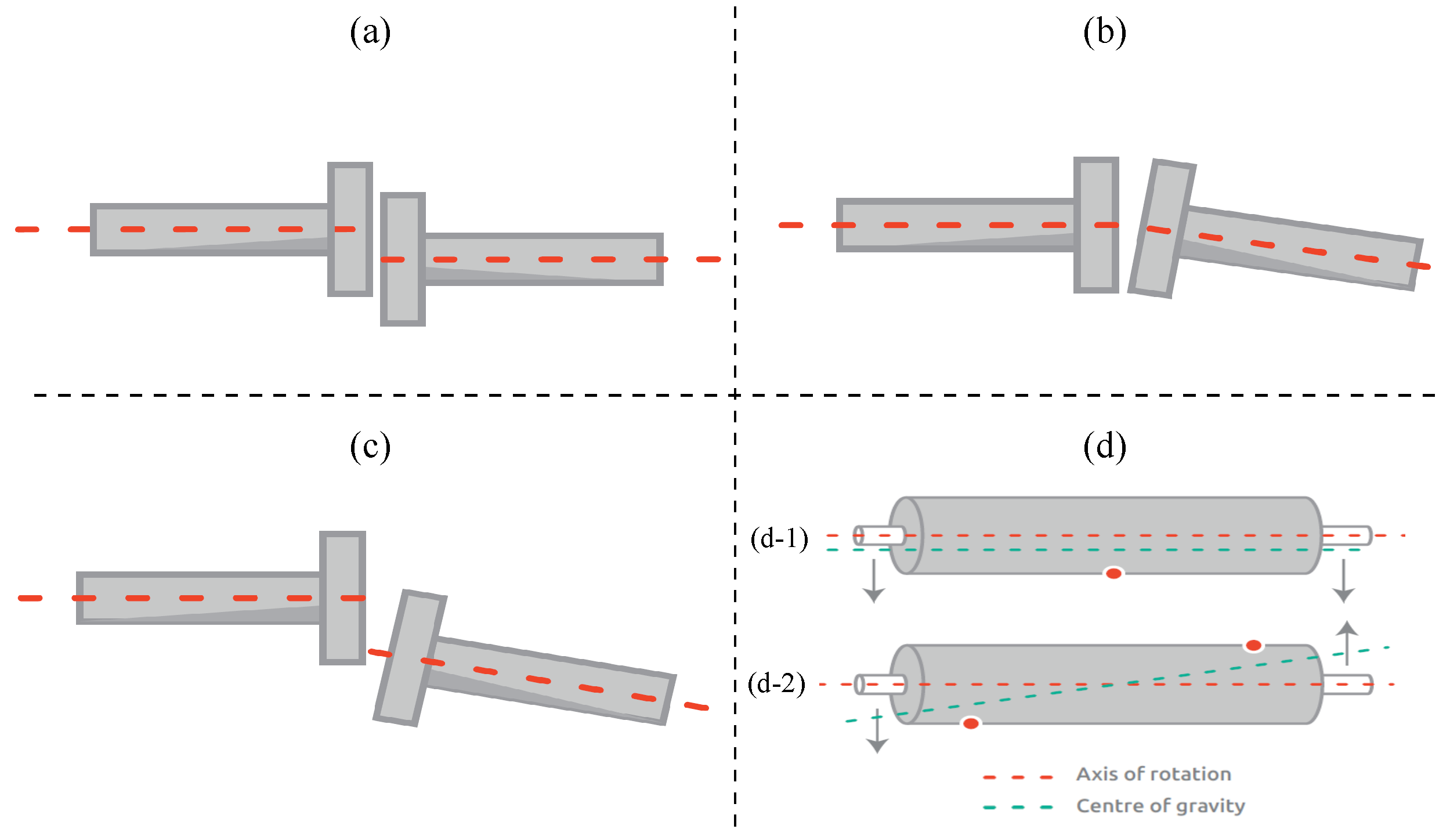
Vibration analysis is employed to monitor the condition of equipment, with the effectiveness of extracting vibration signals playing a crucial role in diagnosing rotating element [25]. Figure 2 shows some common faults that could appear in the rotating parts of wind turbines. The misalignment in rotating machines occurs when the center-lines of coupled shafts do not align properly. This condition can lead to increased vibration, excessive wear, and the potential failure of machine components [26,27]. This fault can be categorized into parallel (or offset) misalignment and angular misalignment, each causing distinct stress patterns and operational issues. However, unbalance is the most common fault in rotors and is defined as unequal mass distribution around the rotor’s rotation center. It is the product of a mass and its eccentricity, which is the distance between the center of gravity of the rotor and its rotational axis. Due to this eccentricity, the unbalance force pulls the rotor to a specific orientation or location, also known as the heavy spot [28,29]. These defects typically cause vibrations throughout the entire structure of the wind turbine. Therefore, addressing misalignment and unbalance is essential for ensuring the efficient and reliable operation of wind turbines.
Incorporating electromechanical transducers is suitable in predictive maintenance, which aims to enhance performance and mitigate environmental consequences by preventing significant failures. Several studies are dedicated to rotor condition monitoring through the application of vibration analysis techniques [30,31,32]. Malla et al. [33] published a paper focusing on vibration monitoring of machine bearings. They provided a concise overview covering bearing defects, sources of vibration, and techniques for vibration measurement in the time domain, frequency domain, and time–frequency domain. The research indicates that both casing analysis and time–frequency analysis methods are proficient in detecting bearing defects effectively. Additionally, wavelet analysis techniques, when combined with artificial neural networks and fuzzy logic, emerge as the most effective approaches for fault analysis in bearings. S. Sheng [34] compiled a report on monitoring the condition of wind turbine gearboxes using vibration analysis, with a focus on large-scale wind turbines. Given that most failures stem from transmission faults, particularly in the main gearbox, various research works have been presented on this topic. Jonas et al. [35] introduced a novel method for identifying flaws in the transmission chain through vibration analysis. This method utilizes convolutional auto-encoders to automatically pinpoint and extract crucial features across a broad-spectrum range, streamlining the process and reducing time and resources. The study showcased the model’s capability to recognize faults in generator bearings and gearbox components based on their vibration patterns. In the following, we present previous research studies carried out for the condition monitoring and sustainable predictive maintenance of wind turbines using vibration sensors.

1.2. Condition Monitoring Systems Based on Piezoelectric Devices

Historically, electrical strain gauges have been employed to assess stress distribution in specific areas, while most piezoelectric sensors have been used to gauge dynamic responses and conduct modal analysis across entire system body. Recent technological progress enables the application of emerging sensors to detect various intrinsic properties of dynamic assets for abnormality detection purposes [36].
Piezoelectric accelerometers are more appropriate for measuring low-frequency and low-acceleration vibrations due to their distinct advantages over other sensor types. These include the ability to measure almost imperceptible vibrations over a wide frequency range with high sensitivity, and the ability to integrate output signals for velocity and displacement measurements [37]. The accelerometers used in predictive maintenance convert the structure’s mechanical vibration to an electrical signal transmitted to an external unity. Selecting the appropriate vibration sensor for the application is crucial for vibration measurements. The signal provided constitutes the input to the processing unit and forms the basis of vibration analysis. For wind turbines, three types of accelerometers are used:
  • Piezoelectric sensors (PEs);
  • Integrated Electronics Piezoelectric (IEPE);
  • Micro electromechanical systems (MEMSs).
Table 1 details the characteristics of the previously mentioned vibration sensors, and provides comprehensive information on several key parameters. These parameters include the operational temperature ranges, which specify the minimum and maximum temperatures at which each sensor can function effectively. The table also outlines the frequency measurement ranges by indicating the spectrum of vibration frequencies each sensor can accurately detect. Additionally, it covers the acceleration measurement ranges, describing the limits of acceleration each sensor can measure. Further, it gives an idea of the sensor sizes, as well as their sensitivity levels, which indicates how responsive each sensor is to vibrations. This detailed breakdown allows for a clear comparison of the performance and suitability of each sensor for different applications.
The piezoelectric accelerometers are renowned for their reliability and range in both frequency and amplitude. Using the piezoelectric direct effect [38,39,40], these sensors excel in detecting high-frequency vibrations and operate well across various temperatures, which makes them ideal for harsh environments like wind turbines. Their sensitivity ensures high-resolution data, although they often require an external power source. MEMS and IEPE accelerometers offer lower accuracy in frequency and amplitude, but they are advantageous in power consumption. They integrate the sensor and circuitry into a single chip, making the devices compact and lightweight [41,42]. This integration enhances reliability and reduces noise interference. In addition, they can detect both static and dynamic acceleration, which makes them ideal for low-frequency vibration monitoring and suitable for applications such as wind turbine health monitoring. Their low power needs are beneficial for remote or battery-powered setups, but this comes at the cost of lower sensitivity and a narrower frequency range.
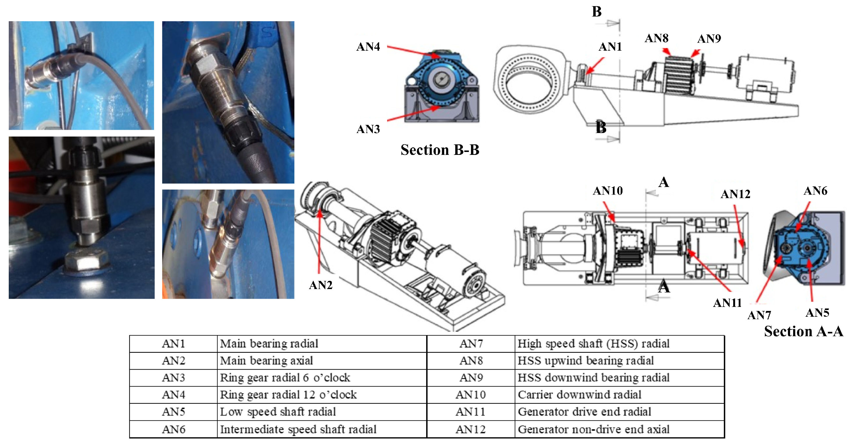
The physical installation of the piezoelectric accelerometers on the wind turbine transmission chain is shown in Figure 3 [34,43]. The figure shows the gearbox, which includes different types of bearings, the shafts, and the generator, all equipped with sensors. It also labels the accelerometer numbers and their positions along the transmission chain. The mounting locations were chosen to reflect typical sensor placement practices in vibration-based commercial wind turbine drivetrain condition monitoring systems (CMSs).
The accelerometers are typically composed of piezoelectric elements and characterized by high bandwidth. The piezoelectric element is able to convert mechanical stress energy into electrical energy. Accelerometers operate by converting vibrational energy into an electrical signal of the same frequency proportional to the object’s instantaneous acceleration. This capability allows for the detection of any abnormalities based on the vibration signature of the part being monitored [44]. Modern accelerometer acquisition systems usually include A/D converters and feature extraction circuitry so that they can receive and analyze a very large number of events per second, enabling many sources to be captured and investigated. The most important aspect of accelerometers, compared to other sensors, is that they do not require a secondary artificial excitation from the use into the monitored structure. Accelerometer sensors operate by being subjected to vibrations generated by the host structure. Referring to regulations targeting environmental protection, the use of lead derivatives is restricted. Ongoing research efforts have resulted in the development of lead-free piezoelectric materials, exhibiting promising performance [45,46,47]. Lead-free piezoelectric materials, including bismuth-based compounds, potassium sodium niobate, and modified barium titanate life cycle assessment are studied as an alternative to lead zirconate titanate (PZT) piezoelectric ceramics [48,49]. The main goal is to offer environmentally friendly alternatives while respecting the proper functioning and performance of the systems.

1.3. Scientific Contribution and Manuscript Structure

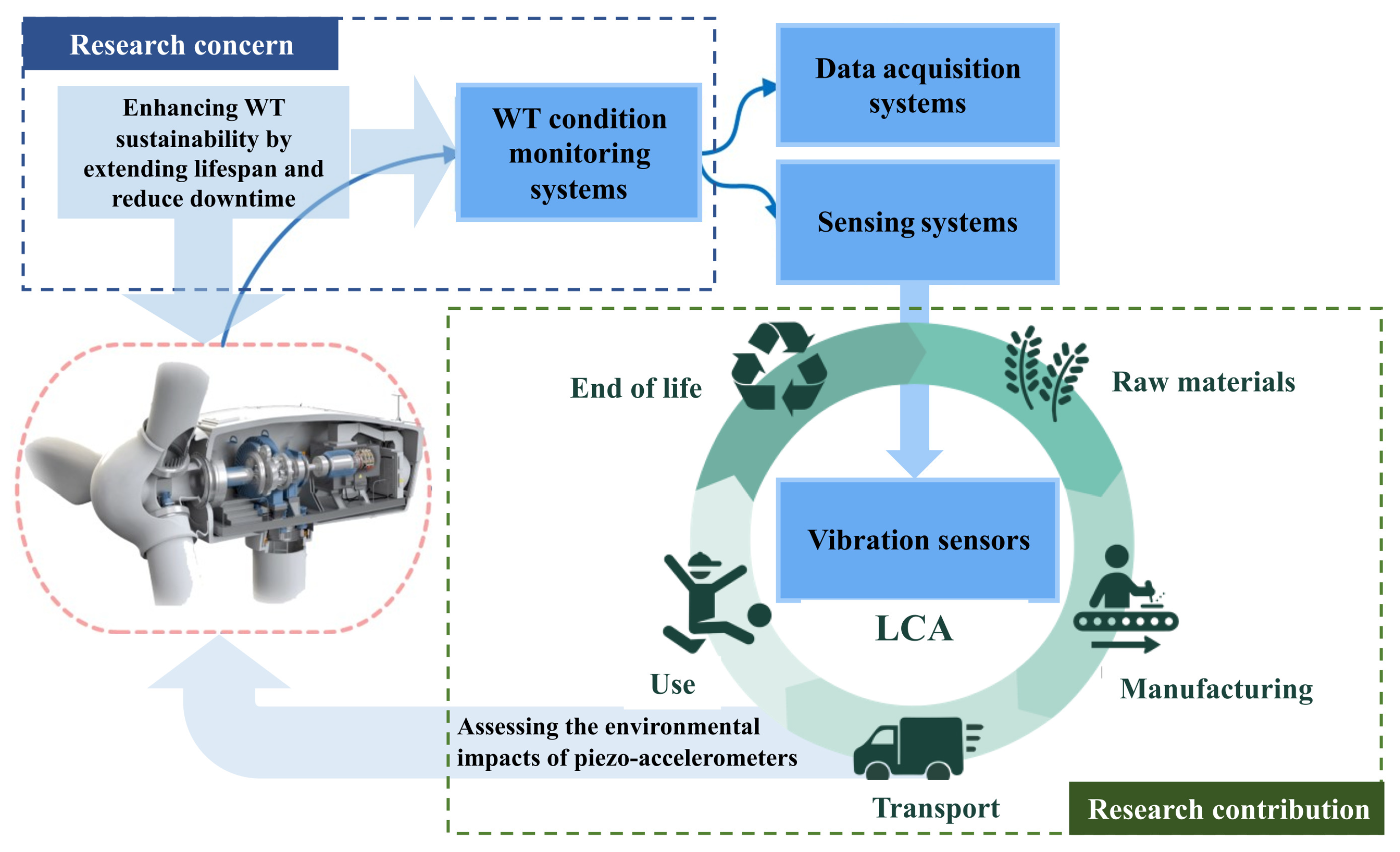
Similar to several prior research efforts, this article examines the environmental assessment of wind turbines within the context of sustainability [50,51,52]. However, the originality of this research lies in its examination of sustainability at the level of monitoring systems. Although these systems are smaller and less complex to manage, they come at an environmental cost. Monitoring the operating conditions of wind turbines also contributes to sustainability by extending their lifespan and reducing downtime [53,54]. This research underscores the interdependence of these issues with a focus on the potential environmental impacts of implementing monitoring systems, in particular, vibrations sensors. It is therefore crucial to achieve a balance to ensure monitoring with more ecological systems. This requires considering the subject comprehensively and evaluating the target from all perspectives. Figure 4 introduces the research question and our scientific contribution to sustainability issues.
Existing studies often overlook vibration sensors and their implications for wind turbine sustainability [55,56]. These sensors capture the vibration signatures generated by rotating parts and enable the early detection of abnormalities and potential faults. However, it is unclear whether their use is ecological and what environmental consequences may arise throughout their life cycle. This article fits into this context by contributing to fill this research gap. Therefore, the objectives of our scientific contribution are as follows:
(1)
Providing more complete data, which have never been gathered, on how these sensors impact the environment by conducting an LCA of a commonly used piezoelectric accelerometer in wind turbine CMSs.
(2)
Highlighting the utility of LCA results in better guide decision-making and drive the ecodesign of monitoring systems and vibration sensors, thereby improving the sustainability of wind turbines.
Following the introduction, which outlines the advancements in wind turbine ecodesign and sustainability by emphasizing the importance of condition monitoring and predictive maintenance with piezoelectric-based devices, the article will then include the following topics, respectively: The methodology to conduct an LCA on a piezoelectric accelerometer to evaluate its environmental impacts is introduced in Section 2. It also covers the life cycle inventory (LCI) that involves disassembling the sensor by identifying the materials, measuring their weights, and determining the manufacturing processes. This offers a preliminary understanding of the sensor’s physics. Section 3 is dedicated to the results and discussion by incorporating the life cycle impact assessment (LCIA) for the impact categories calculated using the European ILCD 2011 Midpoint+ method. Additionally, the results are discussed with appropriate interpretations. Finally, Section 4 presents the conclusions and technical recommendations for design improvement and sustainability.

2. Materials and Methods

The case study involves conducting an LCA on a typical shear-mode piezoelectric accelerometer used in wind turbine CMSs. As outlined in the introduction, the environmental consequences of this accelerometer will be evaluated across its life cycle. Figure 5 highlights the research question and our scientific contribution by illustrating the connections between the topics discussed and the methods employed in this study. This figure serves to clarify the relationships between wind turbine condition monitoring, the environmental impact of the accelerometers, and the overarching goals of sustainability and efficiency in wind energy systems.
The standardized methods for performing an LCA are defined by the ISO 14040 and ISO 14044 standards. These state that an LCA is built up from four main stages [57,58], the goal and scope definition, the LCI, the LCIA, and the interpretation stage as shown in Figure 6. This methodology ensures the accuracy and comparability between assessments performed by different entities.
Our LCA study concentrates on assessing the accelerometer as a vibration sensor, along with examining resource consumption and environmental emissions. This includes considerations of materials, energy sources, transportation, manufacturing, and other related factors. The Ecoinvent 3 database comprises LCI data across multiple sectors, including energy production, transportation, chemical manufacturing, metal production, and others [59,60]. This extensive database is composed of over 10 4 interrelated datasets, with each dataset detailing an LCI at the process level.
The study is performed using SimaPro software that offers six libraries encompassing the complete array of processes from the Ecoinvent database. These libraries employ distinct system models and encompass both unit and system processes. Within these libraries, the Ecoinvent database is represented through three primary system models: allocation at point of substitution, cut-off by classification, and consequential [61]. The “allocation, recycled content” or “cut-off” system model operates on the principle that the primary production of materials is always attributed to the initial user of the material. When a material is recycled, the original producer does not receive any credit for supplying recyclable materials.

2.1. Goal and Scope Definition

Conducting an LCA for the accelerometer used in the vibration measurements of wind turbines involves several key steps. The goals of the study are given below:
  • Understand the environmental impacts associated with the production and disposal of the accelerometer.
  • Identify the stages in the life cycle that contribute most significantly to the overall environmental burden.
  • Provide data to inform design improvements or decision-making for reducing the environmental impact.
The characteristics of the studied accelerometer are presented in Table 2, with data gathered from the manufacturer’s technical data sheet (TDS). These specific characteristics enable the accelerometer to fulfill its functional unit throughout its lifespan. Therefore, any design change must maintain at least these characteristics to meet the fundamental requirements of ecodesign.
Table 3 presents the scope keys of the LCA, including the functional unit, lifespan, system boundaries, evaluation method, and environmental impact categories considered. This table provides a clear and concise summary of the fundamental aspects of the LCA, ensuring a comprehensive understanding of the assessment’s parameters and objectives.
The study includes some hypotheses depending on the transport and location of manufacturing. It is assumed that all parts of the accelerometer were manufactured in France. Furthermore, the supply chain is also ensured on French territories and does not cross borders within a radius of 537 km. Electrical energy consumption is also estimated on certain manufacturing processes based on similarities to previous research studies.

2.2. Life Cycle Inventory Analysis

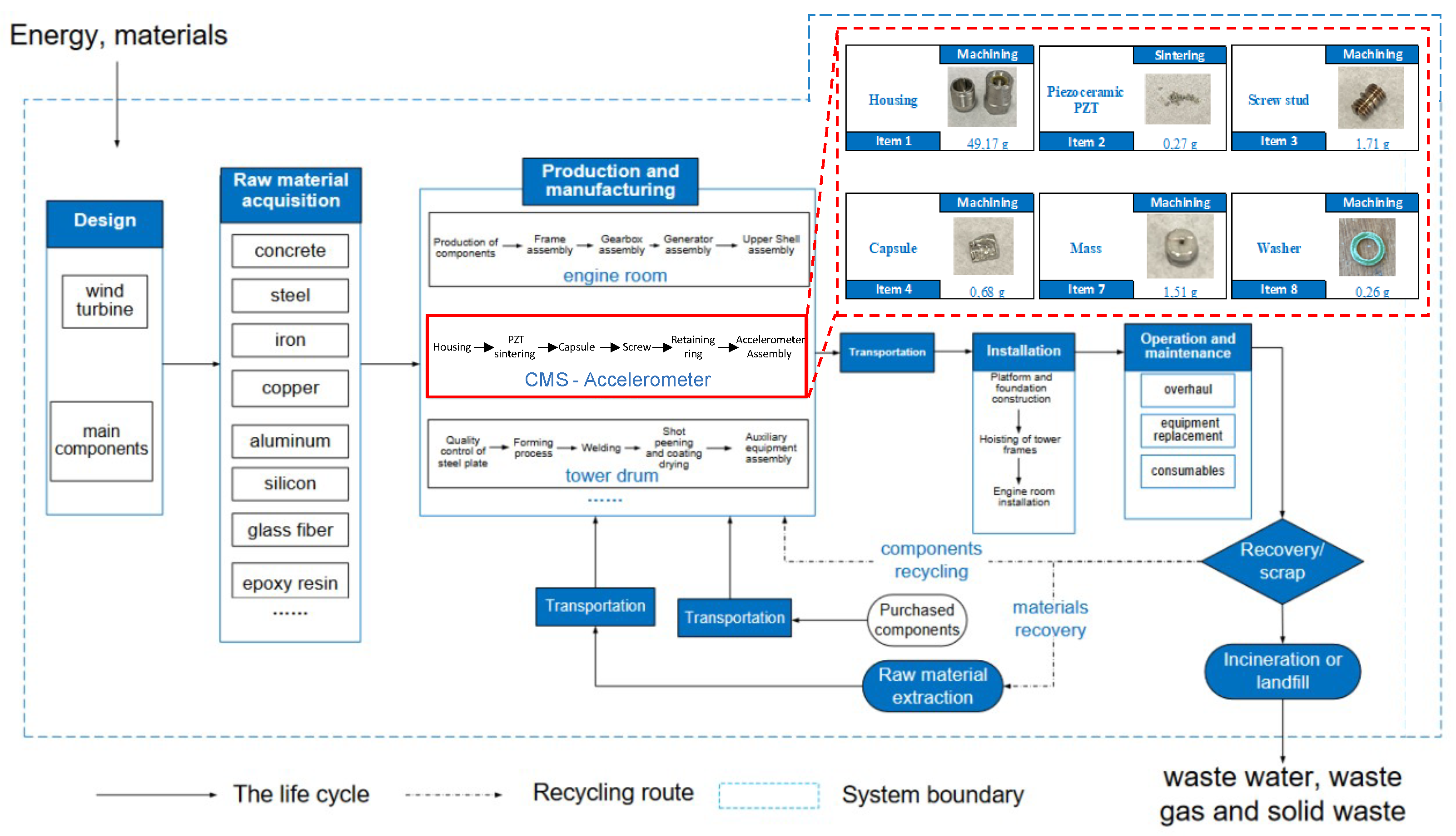
The life cycle inventory consists of analyzing the overall input/output materials, energy, and waste throughout the supply chain of the accelerometer. Figure 7 presents the system boundaries considered in this LCA case study given for a wind turbine with a focus on the CMS and accelerometers, effectively mapping out the various stages of the product’s life cycle from cradle to grave. This comprehensive map details the journey of the product by highlighting each stage from the extraction of raw materials to the point where the product is ready for elimination/recycle. The map begins with the raw material extraction stage, which relies on data powered by the Ecoinvent 3 database. This step involves identifying and assigning chemical compositions to each part, which ensures that the specific materials and their respective impacts are properly considered. The next stage encompasses the manufacturing processes, which are defined by their electrical energy consumption, allowing for precise quantification of the energy required to produce each component. This involves gathering data on all inputs (materials, energy) and outputs (emissions, waste) for each life cycle stage as mentioned in the system boundaries.
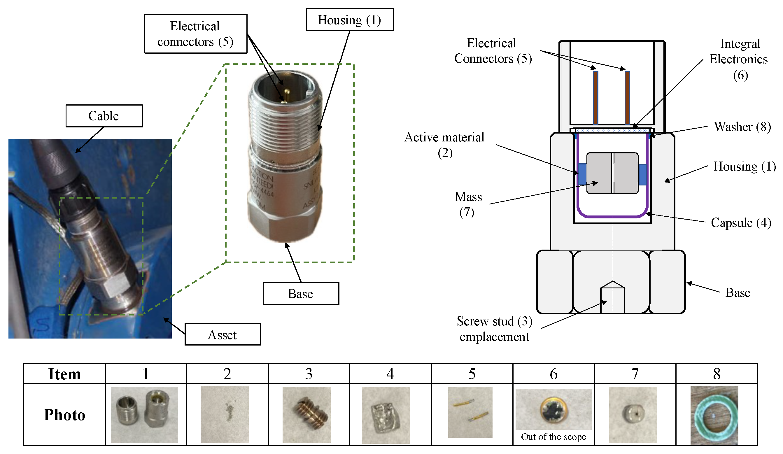
Figure 8 offers an enlarged view of the accelerometer, meticulously detailing all its components. The accelerometer’s architecture is designed as a 3-axis device that operates in shear mode, that enhances its sensitivity and accuracy in detecting vibrations. The piezoelectric element (2) is the core of the system, which is placed between the seismic mass (7) and the capsule (4). This element is crucial for converting mechanical vibrations into electrical signals. The piezoelectric element is connected to the electronics (6), which process the signals generated by the vibrations. These electronics are safeguarded by the washer (8). All these components are embedded within a robust stainless-steel housing (1), providing protection against environmental factors and mechanical damage. For installation, the accelerometer is mounted onto the asset using a screw stud (3), ensuring a secure attachment that maintains the accuracy of the measurements. The device is then connected to a cable through the electrical connectors (5), facilitating the transmission of data to monitoring systems.
In addition to the physical description, an inventory is conducted to evaluate the environmental impact of the accelerometer. This involves identifying each part in terms of its weight, quantity, specified material, and manufacturing process. These details are documented in Table 4, which also indicates whether each component is covered by the Simapro databases, a comprehensive resource for LCA data. However, it is important to note that the electronic circuit (6) and the washer (8) are excluded from this study. These components are subject to specific regulations that necessitate their separate consideration in environmental assessments. This exclusion underscores the need for compliance with regulatory standards while evaluating the overall environmental footprint of the accelerometer.
To accurately determine the weight percentage of piezoceramic lead zirconate titanate (PZT) chemical compositions, we employed energy-dispersive X-ray spectroscopy (EDXS), a powerful analytical technique that provides elemental analysis and chemical characterization of materials. Figure 9 illustrates the EDXS spectrum for the PZT specimen, which was obtained under specific experimental conditions to ensure precise and reliable results. The measurements were conducted with 20 kV and 0.25 microseconds, and the specimen was positioned at a 0°-tilt angle to avoid any geometric distortions that could affect the accuracy of the data. An acquisition time of 30 s was chosen to accumulate sufficient X-ray counts, which enhances the statistical validity of the detected signals and ensures a clear and comprehensive spectrum.
These experimental parameters were carefully chosen to balance the trade-offs between the resolution, sensitivity, and potential sample degradation. The resulting spectrum reveals the characteristic peaks corresponding to lead (Pb), zirconium (Zr), and titanium (Ti) along with oxygen (O), the primary constituents of the PZT material. By analyzing the intensities of these peaks, we quantitatively determine the weight percentages of the elements present whose composition values are given in Table 5. The piezoelectric material used in this study is Pb(ZrTi)O3, which corresponds to a lead zirconate titanate (PZT) piezoceramic. This specific composition exhibits the following properties: a Curie temperature of 330 K, a piezoelectric coupling coefficient kp of 0.56, and piezoelectric coefficients d 31 of 130 and d 33 of 330.
The use of Pb derivatives is restricted, referring to regulations targeting environmental protection [46]. Ongoing research efforts have resulted in the development of lead-free piezoelectric materials exhibiting promising performance [64,65]. Since the EDXS results confirm that the active material is a lead-based PZT, we address this aspect in our LCA study in accordance with the regulatory requirements.

3. Results and Discussion

3.1. Life Cycle Impact Assessment

For the impact assessment, the Environmental Footprint (EF) method is used to calculate the following impact categories [63,66]: acidification, climate change, ecotoxicity (freshwater), energy resources (non-renewable), eutrophication (freshwater), eutrophication (marine), eutrophication (terrestrial), human toxicity (carcinogenic), human toxicity (non-carcinogenic), ionizing radiation, land use, material resources (metals/ minerals), ozone depletion, particulate matter formation, photochemical oxidant formation, and water use. The impact categories calculated in this study are listed in Table 6.

3.2. Interpretation of Results

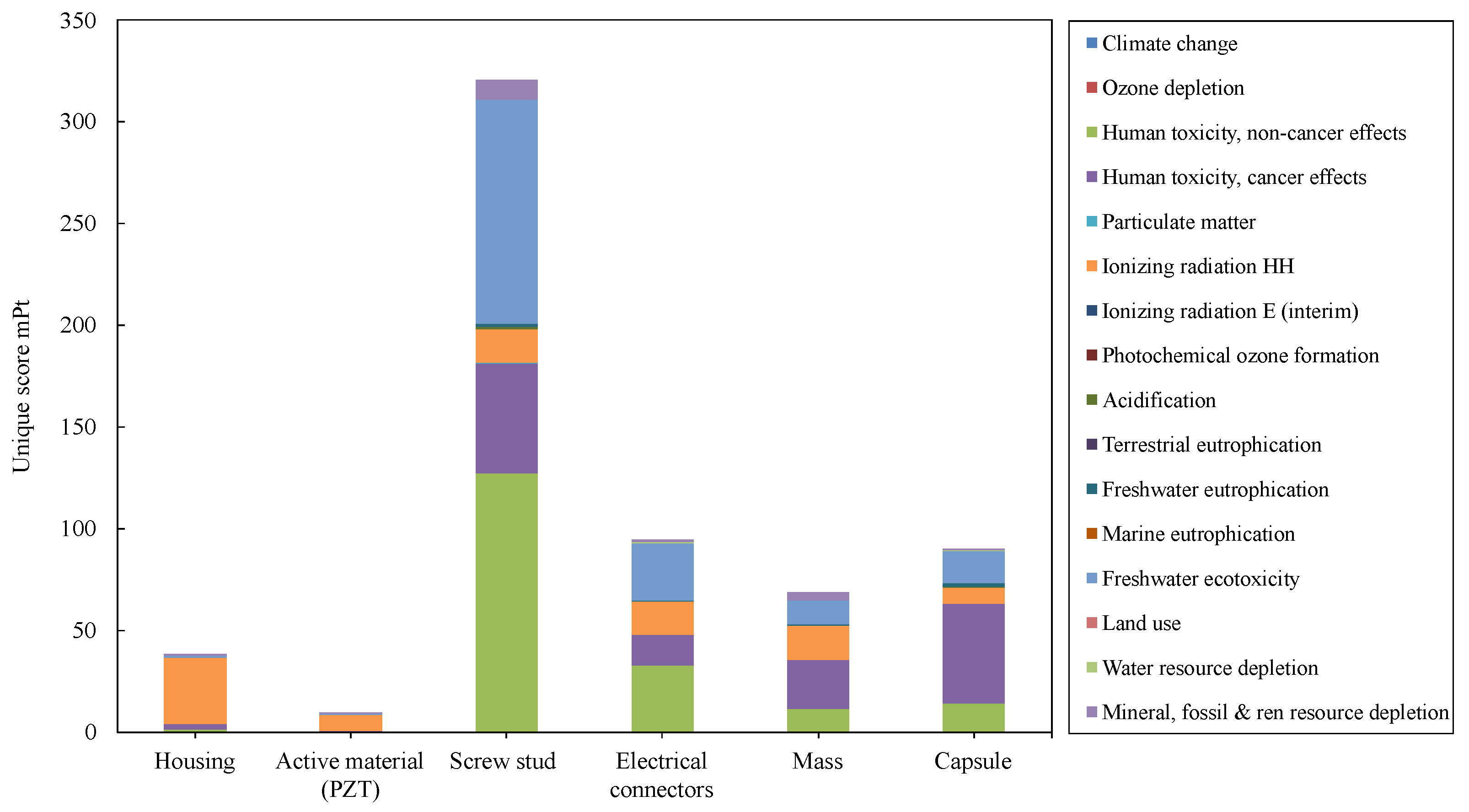
Figure 10 shows the unique score in milli-Points (mPt) computed for the main parts of the accelerometer in this LCA study. The unique score is given for the 16 impact categories selected at the Midpoint as mentioned above. Results show that the most impactful part of the accelerometer is the screw stud, followed by the electrical connectors and the capsule in second place. For the screw stud, connectors and capsule, we note that the highest impact categories are human toxicity (cancer and non-cancer effects) and freshwater ecotoxicity, then ionizing radiation HH. The copper parts (i.e., screw stud and electrical connectors) exhibit higher human toxicity without carcinogenic effects than that with carcinogenic effects, while the capsule exhibits the opposite. We also note that ionizing radiation has significant effects for all parts of the accelerometer. This is due to the energy mix used in the study which is from French production of high-voltage nuclear electricity. The results show that piezoceramic PZT has a lower unique score compared to other components of the accelerometer. The most significant impact is from ionizing radiation at 8.185 mPt, followed by human toxicity non-cancer effects at 0.396 mPt and human toxicity cancer effects at 0.42 mPt as shown in Table 6. These unique score values are almost negligible, likely due to their proportional relationship to the quantities used.
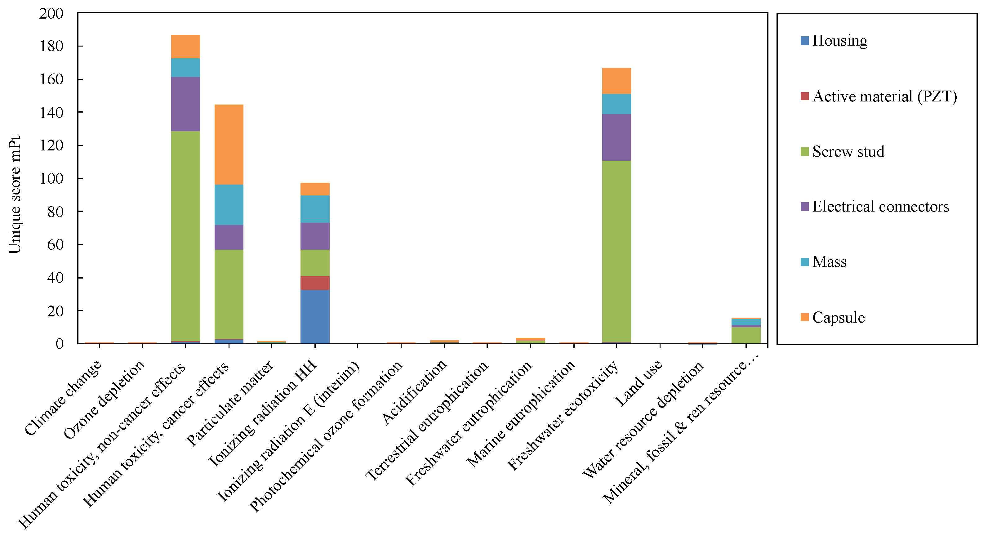
Figure 11 presents the unique score versus the Midpoint impact categories for the accelerometer assembly parts. The impact categories with the highest unique scores are human toxicity non-cancer effects, freshwater ecotoxicity, human toxicity cancer effects, and ionizing radiation HH, respectively. These categories are particularly notable for their significant environmental impacts compared to others. Categories such as mineral, fossil and renewable resource depletion, freshwater eutrophication, acidification, and particulate matter exhibit low unique scores, which means that the environmental consequences associated with these impact categories are not significant compared to the impact categories mentioned first. In contrast, climate change, ozone depletion, and other categories have negligible or non-existent environmental impacts. This suggests that the materials and processes involved in the accelerometer assembly have a minimal effect on resource depletion. The individual unique scores for the different impact categories given in Table 6 confirm these observations. The analysis further reveals that certain components within the accelerometer assembly contribute disproportionately to environmental impacts. Specifically, the screw stud, electrical connectors, and capsule have the most significant contributions to human toxicity non-cancer effects, freshwater ecotoxicity, and human toxicity cancer effects. This implies that the materials and manufacturing processes used for these parts involve substances or practices that are particularly harmful to human health and aquatic ecosystems. For the ionizing radiation HH category, the housing body is identified as the most impactful part, followed by the seismic mass. This indicates that the production or material composition of the housing body involves sources of ionizing radiation, potentially due to specific manufacturing techniques or materials that have higher radiation emissions. The environmental impact of the accelerometer’s active material PZT is especially significant in terms of ionizing radiation and human toxicity. Ionizing radiation is primarily associated with the energy mix employed in various stages of production, including the manufacturing processes of PZT. This type of radiation arises from the use of nuclear energy, which is a major component of the electricity mix in France.
French electricity generation is heavily dependent on nuclear power, with uranium-based reactors contributing over 68% of the total energy mix. This reliance on nuclear energy means that the processes involved in producing PZT, and consequently the accelerometer, are subject to the environmental burdens associated with nuclear power. These burdens include the generation of ionizing radiation, which poses significant environmental and health risks. Human toxicity is another critical impact category influenced by the production and use of PZT. The materials and processes involved in manufacturing PZT can release toxic substances that affect human health. In the context of nuclear energy, the extraction, processing, and disposal of uranium and other radioactive materials contribute to human toxicity. These activities can lead to the release of harmful substances into the environment, potentially causing adverse health effects over time. Overall, the environmental consequences of using PZT in accelerometers are closely tied to the energy sources and industrial practices involved in its production. The heavy reliance on nuclear power in France amplifies the impacts of ionizing radiation and human toxicity, highlighting the need for the careful consideration of energy and material choices in the design and manufacturing of electronic components. Despite regulatory restrictions on using lead-based piezoelectric materials, this research shows that the PZT element used in the accelerometer has the least impact. This element could benefit from an exemption for such use, subject to the quantity used.
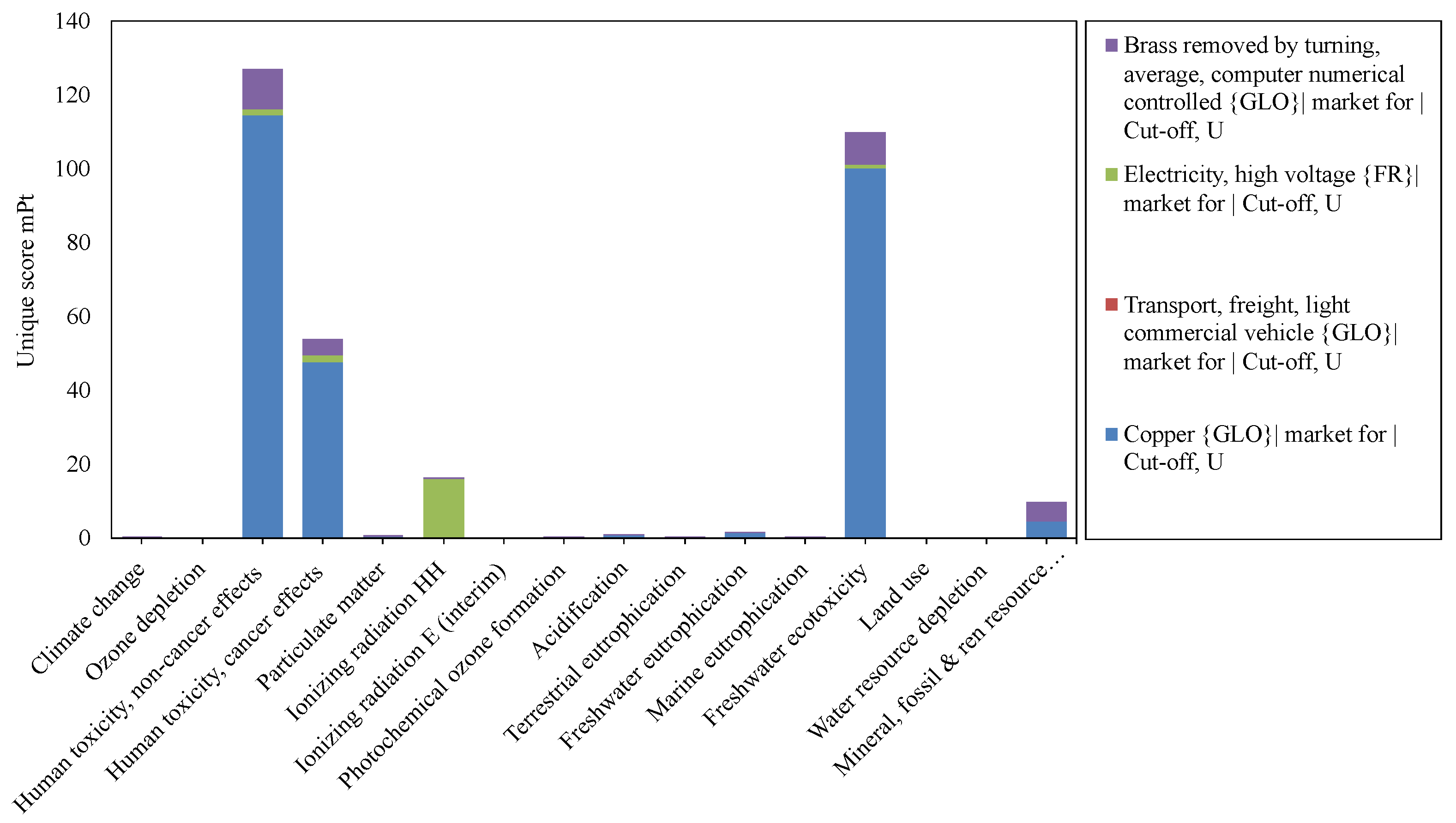
Figure 12 presents the unique score versus the Midpoint impact categories for the copper extraction, transport, energy consumption, and manufacturing process. The results indicate that the human toxicity non-cancer effects, freshwater ecotoxicity, human toxicity cancer effects, ionizing radiation HH, and the mineral, fossil and renewable resources exhibit the highest values, respectively, compared to the other categories. This suggests that these five impact categories are the most significantly affected by the copper extraction and related processes. It is evident from the data that copper extraction is the most impactful process across all environmental impact categories. This is likely due to the intensive nature of the mining and refining processes, which involve substantial disruption of the environment and significant chemical usage. Following copper extraction, the manufacturing process is the second most impactful stage. This can be attributed to the energy-intensive nature of manufacturing and the associated emissions and resource consumption.
Energy consumption also plays a critical role, particularly in the ionizing radiation HH category, where it presents a high unique value. This high value is likely due to the types of energy sources used, which may include nuclear power, known for its ionizing radiation emissions. Conversely, energy consumption has a negligible impact on other categories, which indicates that while energy use is a critical factor in certain environmental impacts, its overall contribution to other impact categories is minimal. Furthermore, transport is necessary for the entire life cycle of copper products, while it appears to have a lesser impact on the Midpoint categories compared to extraction and manufacturing. This could be due to more efficient transportation methods or lower relative emissions compared to the intensive processes of extraction and manufacturing. Overall, the analysis underscores the need for targeted environmental strategies. For example, improving the efficiency and environmental management of copper extraction and manufacturing could yield significant reductions in human toxicity and freshwater ecotoxicity. Additionally, exploring cleaner energy sources could mitigate the ionizing radiation impacts associated with energy consumption. Addressing these areas can help in reducing the overall environmental footprint of copper production. Figure 13 presents pie charts that illustrate the unique score corresponding to the copper extraction for various impact categories. These results specifically pertain to the screw stud component, offering a detailed visual representation of how copper extraction influences each environmental impact category.

4. Conclusions

The LCA reveals valuable results about the studied accelerometer across its life cycle. The impact assessment of accelerometer components reveals that the screw stud, electrical connectors, and capsule are the most environmentally impactful parts, primarily due to their high scores in human toxicity (both cancer and non-cancer effects) and freshwater ecotoxicity. The active material PZT has lower overall environmental impacts, with ionizing radiation being the most significant, which is followed by non-cancer and cancer human toxicity effects. These values are relatively low, likely due to the proportional quantities used. In addition, production processes involving nuclear energy, prevalent in France’s electricity mix, significantly contribute to ionizing radiation impacts. We list the main findings and issued recommendations of our study below:
(1)
Parts made from copper have the most significant impact on the environment, so changing materials or manufacturing processes and practices can mitigate this impact. It is also possible to change the architecture of the accelerometer by eliminating the screw stud while favoring another type of fastening (e.g., mounting with a magnet or by structural bonding).
(2)
The Piezoceramic PZT element has the least impact on the environment; however, there are regulatory restrictions on its use due to the dominant presence of lead in its chemical composition. This means that its substitution with another alternative lead-free material is always preferable.
(3)
The study highlights that ionizing radiation and human toxicity are major environmental concerns, particularly due to the heavy reliance on nuclear energy in France. This underscores the importance of considering energy sources in the ecodesign to minimize environmental and health risks.
In addition to the conclusive results obtained by our study, several shortcomings were identified and are listed as follows:
  • Our study employs a partial LCA due to the difficulty of obtaining comprehensive data for all life cycle stages. Detailed information on materials, manufacturing processes, and end-of-life treatments are very limited in the literature; additionally, the Ecoinvent database provides generic data that can potentially skew the results. In addition, assumptions and simplifications might not accurately reflect real conditions.
  • The initial phase of our inventory involves disassembling the accelerometer, as shown in Section 2.2, to identify the materials and manufacturing processes used. Variations in manufacturing practices among different suppliers or production batches, along with the absence of specific data, can result in variability in environmental impacts. Consequently, the available data may be uncertain or variable, potentially leading to inaccuracies in the LCA results.
Future research will aim to enhance data collection to thoroughly encompass all life cycle stages by collaborating with manufacturers to access proprietary data. Furthermore, enriching Ecoinvent databases with specific and accurate data is crucial for obtaining more reliable and comprehensive results. It is also essential to address assumptions and simplifications by conducting sensitivity and uncertainty analyses and by developing more accurate models.

Author Contributions

Conceptualization, R.A.; methodology, R.G. and B.L.; software, R.A. and R.G.; validation, B.C., R.G. and B.L.; formal analysis, R.A.; investigation, R.A. and B.L.; resources, C.V.; data curation, R.A.; writing—original draft preparation, R.A.; writing—review and editing, R.A.; visualization, R.A.; supervision, B.C., R.G. and B.L.; project administration, R.A.; funding acquisition, B.L., B.C. and R.G. All authors have read and agreed to the published version of the manuscript.

Funding

This research received no external funding.

Data Availability Statement

Data sharing is not applicable to this article as we used the existing “Ecoinvent” database, which is subject to commercial restrictions.

Acknowledgments

This work is co-funded by the multidisciplinary initiative « mastery of safe and sustainable technological systems » of the Sorbonne University Alliance. The authors thank UTC for supporting this research through the collaboration between the Roberval and Avenues laboratories.

Conflicts of Interest

The authors confirm no conflicts of interest.

Abbreviations

The following abbreviations are used in this manuscript:
LCALife Cycle Assessment
LCILife Cycle Inventory
LCIALife Cycle Impact Assessment
TDSTechnical Data Sheet
EFEnvironmental Footprint
CMSCondition Monitoring Systems
BOMBill Of Materials
EDXSEnergy-Dispersive X-ray Spectroscopy

References

  1. Desalegn, B.; Gebeyehu, D.; Tamrat, B. Wind energy conversion technologies and engineering approaches to enhancing wind power generation: A review. Heliyon 2022, 8, e11263. [Google Scholar] [CrossRef] [PubMed]
  2. Pourrajabian, A.; Afshar, P.A.N.; Ahmadizadeh, M.; Wood, D. Aero-structural design and optimization of a small wind turbine blade. Renew. Energy 2016, 87, 837–848. [Google Scholar] [CrossRef]
  3. Muhsen, H.; Al-Kouz, W.; Khan, W. Small Wind Turbine Blade Design and Optimization. Symmetry 2019, 12, 18. [Google Scholar] [CrossRef]
  4. Hasan, M.; El-Shahat, A.; Rahman, M. Performance Investigation of Three Combined Airfoils Bladed Small Scale Horizontal Axis wind Turbine by BEM and CFD Analysis. J. Power Energy Eng. 2017, 5, 14–27. [Google Scholar] [CrossRef]
  5. Rehman, S.; Alam, M.; Alhems, L.; Rafique, M. Horizontal Axis Wind Turbine Blade Design Methodologies for Efficiency Enhancement—A Review. Energies 2018, 11, 506. [Google Scholar] [CrossRef]
  6. Sethuraman, L.; Dykes, K. GeneratorSE: A Sizing Tool for Variable-Speed Wind Turbine Generators; Technical Report; National Renewable Energy Laboratory: Washington, DC, USA, 2017; Volume 9. Available online: http://www.osti.gov/servlets/purl/1395455/ (accessed on 2 July 2024).
  7. Li, D.; Zhang, Z.; Zhou, X.; Zhang, Z.; Yang, X. Cross-wind dynamic response of concrete-filled double-skin wind turbine towers: Theoretical modelling and experimental investigation. J. Vib. Control. 2023, 30, 2881–2893. [Google Scholar] [CrossRef]
  8. Kouloumpis, V.; Azapagic, A. A model for estimating life cycle environmental impacts of offshore wind electricity considering specific characteristics of wind farms. Sustain. Prod. Consum. 2022, 29, 495–506. [Google Scholar] [CrossRef]
  9. Rueda-Bayona, J.G.; Eras, J.J.C.; Chaparro, T.R. Impacts generated by the materials used in offshore wind technology on Human Health, Natural Environment and Resources. Energy 2022, 261, 125223. [Google Scholar] [CrossRef]
  10. Martínez, E.; Sanz, F.; Pellegrini, S.; Jiménez, E.; Blanco, J. Life cycle assessment of a multi-megawatt wind turbine. Renew. Energy 2009, 34, 667–673. [Google Scholar] [CrossRef]
  11. Martínez, E.; Jiménez, E.; Blanco, J.; Sanz, F. LCA sensitivity analysis of a multi-megawatt wind turbine. Appl. Energy 2010, 87, 2293–2303. [Google Scholar] [CrossRef]
  12. Tremeac, B.; Meunier, F. Life cycle analysis of 4.5 MW and 250 W wind turbines. Renew. Sustain. Energy Rev. 2009, 13, 2104–2110. [Google Scholar] [CrossRef]
  13. Gaha, R.; Benamara, A.; Yannou, B. Eco-Design of a Basin Mixer in Geometric Modeling Phase. Key Eng. Mater. 2014, 572, 7–11. [Google Scholar] [CrossRef]
  14. Canet, H.; Guilloré, A.; Bottasso, C. The eco-conscious wind turbine: Design beyond purely economic metrics. Wind. Energy Sci. 2023, 8, 1029–1047. [Google Scholar] [CrossRef]
  15. Guilloré, A.; Canet, H.; Bottasso, C. Life Cycle Environmental Impact of Wind Turbines: What are the Possible Improvement Pathways? J. Phys. Conf. Ser. 2022, 2265, 042033. [Google Scholar] [CrossRef]
  16. Bonou, A.; Skelton, K.; Olsen, S. Ecodesign framework for developing wind turbines. J. Clean. Prod. 2016, 126, 643–653. [Google Scholar] [CrossRef]
  17. Martinez-Marquez, D.; Florin, N.; Hall, W.; Majewski, P.; Wang, H.; Stewart, R. State-of-the-art review of product stewardship strategies for large composite wind turbine blades. Resour. Conserv. Recycl. Adv. 2022, 15, 200109. [Google Scholar] [CrossRef]
  18. Chu, W.; Lin, C.; Li, M. Active multimode vibration control of a smart structure using macro fiber composite actuators based on ANFIS. J. Low Freq. Noise Vib. Act. Control. 2020, 39, 1187–1203. [Google Scholar] [CrossRef]
  19. Zhang, H.; Sun, W.; Luo, H.; Zhang, R. Modeling and active control of geometrically nonlinear vibration of composite laminates with macro fiber composite. Compos. Struct. 2023, 321, 117292. [Google Scholar] [CrossRef]
  20. Zhou, X.; Ke, Y.; Zhu, J.; Cui, W. Sustainable Operation and Maintenance of Offshore Wind Farms Based on the Deep Wind Forecasting. Sustainability 2023, 16, 333. [Google Scholar] [CrossRef]
  21. Yildirim, M.; Sun, X.; Gebraeel, N. Sensor-Driven Condition-Based Generator Maintenance Scheduling—Part I: Maintenance Problem. IEEE Trans. Power Syst. 2016, 31, 4253–4262. [Google Scholar] [CrossRef]
  22. Tian, Z.; Wang, H. Wind power system reliability and maintenance optimization considering turbine and wind uncertainty. J. Qual. Maint. Eng. 2022, 28, 252–273. [Google Scholar] [CrossRef]
  23. Gaha, R.; Benamara, A.; Yannou, B. An Environmental Impact/Cost Model for Evaluating Multiple Feature-Based Machining Methods. In Design and Modeling of Mechanical Systems—II. Lecture Notes in Mechanical Engineering; Chouchane, M., Fakhfakh, T., Daly, H., Aifaoui, N., Chaari, F., Eds.; Springer: Berlin/Heidelberg, Germany, 2015; pp. 21–27. [Google Scholar]
  24. ISTEC International. E-book: Optimizing WTG Availability and Maintenance Efficiency. Available online: https://www.istec.com/en/ebook-wtg/ (accessed on 2 July 2024).
  25. Vishwakarma, M.; Purohit, R.; Harshlata, V.; Rajput, P. Vibration Analysis & Condition Monitoring for Rotating Machines: A Review. Mater. Today Proc. 2017, 4, 2659–2664. [Google Scholar]
  26. Piotrowski, J. Shaft Alignment Handbook; Taylor & Francis Group: Oxfordshire, UK, 2006. [Google Scholar]
  27. Jalan, A.; Mohanty, A. Model based fault diagnosis of a rotor–bearing system for misalignment and unbalance under steady-state condition. J. Sound Vib. 2009, 327, 604–622. [Google Scholar] [CrossRef]
  28. Tahir, M.; Hussain, A.; Badshah, S.; Khan, A.; Iqbal, N. Classification of unbalance and misalignment faults in rotor using multi-axis time domain features. In Proceedings of the 2016 International Conference On Emerging Technologies (ICET), Islamabad, Pakistan, 18–19 October 2016; pp. 1–4. [Google Scholar]
  29. Yamamoto, G.; Da Costa, C.; Da Silva Sousa, J.S. A smart experimental setup for vibration measurement and imbalance fault detection in rotating machinery. Case Stud. Mech. Syst. Signal Process. 2016, 4, 8–18. [Google Scholar] [CrossRef]
  30. Mathew, J.; Alfredson, R. The Condition Monitoring of Rolling Element Bearings Using Vibration Analysis. J. Vib. Acoust. Stress. Reliab. Des. 1984, 106, 447–453. [Google Scholar] [CrossRef]
  31. Dalpiaz, G.; Rivola, A. Condition Monitoring and Diagnostics in Automatic Machines: Comparison of Vibration Analysis Techniques. Mech. Syst. Signal Process. 1997, 11, 53–73. [Google Scholar] [CrossRef]
  32. KiranKumar, M.; Lokesha, M.; Kumar, S.; Kumar, A. Review on Condition Monitoring of Bearings using vibration analysis techniques. IOP Conf. Ser. Mater. Sci. Eng. 2018, 376, 012110. [Google Scholar] [CrossRef]
  33. Malla, C.; Panigrahi, I. Review of Condition Monitoring of Rolling Element Bearing Using Vibration Analysis and Other Techniques. J. Vib. Eng. Technol. 2019, 7, 407–414. [Google Scholar] [CrossRef]
  34. Sheng, S. Wind Turbine Gearbox Condition Monitoring Round Robin Study—Vibration Analysis; National Renewable Energy Lab. (NREL): Golden, CO, USA, 2012; Volume 7. Available online: https://www.osti.gov/biblio/1048981 (accessed on 2 July 2024).
  35. Jonas, S.; Anagnostos, D.; Brodbeck, B.; Meyer, A. Vibration Fault Detection in Wind Turbines Based on Normal Behaviour Models without Feature Engineering. Energies 2023, 16, 1760. [Google Scholar] [CrossRef]
  36. Li, D.; Ho, S.; Song, G.; Ren, L.; Li, H. A review of damage detection methods for wind turbine blades. Smart Mater. Struct. 2015, 24, 033001. [Google Scholar] [CrossRef]
  37. Metra Mess und Frequenztechnik. Piezoelectric Accelerometers Theory and Application; Metra Mess und Frequenztechnik: Radebeul, Germany, 2001. [Google Scholar]
  38. Aloui, R.; Larbi, W.; Chouchane, M. Finite Element Modeling and Analysis of a Bimorph Piezoelectric Energy Harvester. In Design and Modeling of Mechanical Systems—III; Haddar, M., Chaari, F., Benamara, A., Chouchane, M., Karra, C., Aifaoui, N., Eds.; Springer: Cham, Switzerland, 2018; pp. 1205–1214. [Google Scholar]
  39. Aloui, R.; Larbi, W.; Chouchane, M. Sensitivity Analysis of Frequency Response Functions for Load Resistance of Piezoelectric Energy Harvesters. In Advances in Acoustics and Vibration II; Fakhfakh, T., Karra, C., Bouaziz, S., Chaari, F., Haddar, M., Eds.; Springer: Cham, Switzerland, 2018; pp. 136–148. [Google Scholar]
  40. Aloui, R.; Larbi, W.; Chouchane, M. Metamodeling and Sensitivity Analysis of a Piezoelectric Energy Harvester Based on Polynomial Chaos Expansions. In Advances in Nonlinear Dynamics and Control of Mechanical and Physical Systems; Belhaq, M., Ed.; Springer: Singapore, 2024; pp. 165–176. [Google Scholar]
  41. Varanis, M.; Silva, A.; Mereles, A.; Pederiva, R. MEMS accelerometers for mechanical vibrations analysis: A comprehensive review with applications. J. Braz. Soc. Mech. Sci. Eng. 2018, 40, 527. [Google Scholar] [CrossRef]
  42. Laine, J.; Mougenot, D. A high-sensitivity MEMS-based accelerometer. Lead. Edge 2014, 33, 1234–1242. [Google Scholar] [CrossRef]
  43. Sheng, S.; Yang, W. Wind Turbine Drivetrain Condition Monitoring—An Overview (Presentation); National Renewable Energy Lab. (NREL): Golden, CO, USA, 2013; Volume 7. Available online: https://www.osti.gov/biblio/1087787 (accessed on 2 July 2024).
  44. Le, T.; Luu, T.; Nguyen, H.; Nguyen, T.; Ho, D.; Huynh, T. Piezoelectric Impedance-Based Structural Health Monitoring of Wind Turbine Structures: Current Status and Future Perspectives. Energies 2022, 15, 5459. [Google Scholar] [CrossRef]
  45. Rödel, J.; Jo, W.; Seifert, K.; Anton, E.; Granzow, T.; Damjanovic, D. Perspective on the Development of Lead-free Piezoceramics. J. Am. Ceram. Soc. 2009, 92, 1153–1177. [Google Scholar] [CrossRef]
  46. Bell, A.; Deubzer, O. Lead-free piezoelectrics—The environmental and regulatory issues. MRS Bull. 2018, 43, 581–587. [Google Scholar] [CrossRef]
  47. Orlik, K.; Lorgouilloux, Y.; Marchet, P.; Thuault, A.; Jean, F.; Rguiti, M.; Courtois, C. Influence of microwave sintering on electrical properties of BCTZ lead free piezoelectric ceramics. J. Eur. Ceram. Soc. 2020, 40, 1212–1216. [Google Scholar] [CrossRef]
  48. Ibn-Mohammed, T.; Koh, S.; Reaney, I.; Sinclair, D.; Mustapha, K.; Acquaye, A.; Wang, D. Are lead-free piezoelectrics more environmentally friendly? MRS Commun. 2017, 7, 1–7. [Google Scholar] [CrossRef]
  49. Ibn-Mohammed, T.; Reaney, I.; Koh, S.; Acquaye, A.; Sinclair, D.; Randall, C.A.; Abubakar, F.H.; Smith, L.; Schileo, G.; Ozawa-Meida, L. Life cycle assessment and environmental profile evaluation of lead-free piezoelectrics in comparison with lead zirconate titanate. J. Eur. Ceram. Soc. 2018, 38, 4922–4938. [Google Scholar] [CrossRef]
  50. Pender, K.; Bacharoudis, K.; Romoli, F.; Greaves, P.; Fuller, J. Feasibility of Natural Fibre Usage for Wind Turbine Blade Components: A Structural and Environmental Assessment. Sustainability 2024, 16, 5533. [Google Scholar] [CrossRef]
  51. Atilgan Turkmen, B.; Germirli Babuna, F. Life Cycle Environmental Impacts of Wind Turbines: A Path to Sustainability with Challenges. Sustainability 2024, 16, 5365. [Google Scholar] [CrossRef]
  52. Gkantou, M.; Rebelo, C.; Baniotopoulos, C. Life Cycle Assessment of Tall Onshore Hybrid Steel Wind Turbine Towers. Energies 2020, 13, 3950. [Google Scholar] [CrossRef]
  53. Chang, C.C.W.; Ding, T.J.; Han, W.; Chai, C.C.; Bhuiyan, M.A.; Choon-Yian, H.; Song, T.C. Recent advancements in condition monitoring systems for wind turbines: A review. Energy Rep. 2023, 9, 22–27. [Google Scholar]
  54. Jin, X.; Xu, Z.; Qiao, W. Condition Monitoring of Wind Turbine Generators Using SCADA Data Analysis. IEEE Trans. Sustain. Energy 2021, 12, 202–210. [Google Scholar] [CrossRef]
  55. Leung, D.; Yang, Y. Wind energy development and its environmental impact: A review. Renew. Sustain. Energy Rev. 2012, 16, 1031–1039. [Google Scholar] [CrossRef]
  56. Nazir, M.; Ali, N.; Bilal, M.; Iqbal, H. Potential environmental impacts of wind energy development: A global perspective. Curr. Opin. Environ. Sci. Health 2020, 13, 85–90. [Google Scholar] [CrossRef]
  57. An, J.; Zou, Z.; Chen, G.; Sun, Y.; Liu, R.; Zheng, L. An IoT-Based Life Cycle Assessment Platform of Wind Turbines. Sensors 2021, 21, 1233. [Google Scholar] [CrossRef] [PubMed]
  58. Hagen, L.; Petrick, K.; Wilhelm, S.; Schmehl, R. Life-Cycle Assessment of a Multi-Megawatt Airborne Wind Energy System. Energies 2023, 16, 1750. [Google Scholar] [CrossRef]
  59. Wernet, G.; Bauer, C.; Steubing, B.; Reinhard, J.; Moreno-Ruiz, E.; Weidema, B. The ecoinvent database version 3 (part I): Overview and methodology. Int. J. Life Cycle Assess. 2016, 21, 1218–1230. [Google Scholar] [CrossRef]
  60. Treyer, K.; Bauer, C. Life cycle inventories of electricity generation and power supply in version 3 of the ecoinvent database—part II: Electricity markets. Int. J. Life Cycle Assess. 2016, 21, 1255–1268. [Google Scholar] [CrossRef]
  61. System Models. Available online: https://support.ecoinvent.org/system-models (accessed on 30 May 2024).
  62. Piezotronics, P. Model M603C01—Platinum Low-Cost Industrial ICP® Accelerometer—Installation and Operating Manual. Available online: https://www.pcb.com/products?m=m603c01 (accessed on 2 July 2024).
  63. JRC International Reference Life Cycle Data System (ILCD) Handbook—General Guide for Life Cycle Assessment—Provisions and Action Steps. JRC Public Repository. 2010. Available online: https://publications.jrc.ec.europa.eu/repository/handle/JRC58190 (accessed on 2 July 2024).
  64. Shrout, T.; Zhang, S. Lead-free piezoelectric ceramics: Alternatives for PZT? J. Electroceram. 2007, 19, 113–126. [Google Scholar] [CrossRef]
  65. Nomel, I.; Lelievre, J.; Boyer, L.; Durand-Panteix, O.; Marchet, P. Synthesis of 0.94 Na0.5Bi0.5TiO3–0.06 BaTiO3 (NBT-6BT) lead-free piezoelectric powder suitable for aerosol deposition (AD). Ceram. Int. 2022, 48, 14697–14707. [Google Scholar] [CrossRef]
  66. Naumann, G.; Famiglietti, J.; Schropp, E.; Motta, M.; Gaderer, M. Dynamic life cycle assessment of European electricity generation based on a retrospective approach. Energy Convers. Manag. 2024, 311, 118520. [Google Scholar] [CrossRef]
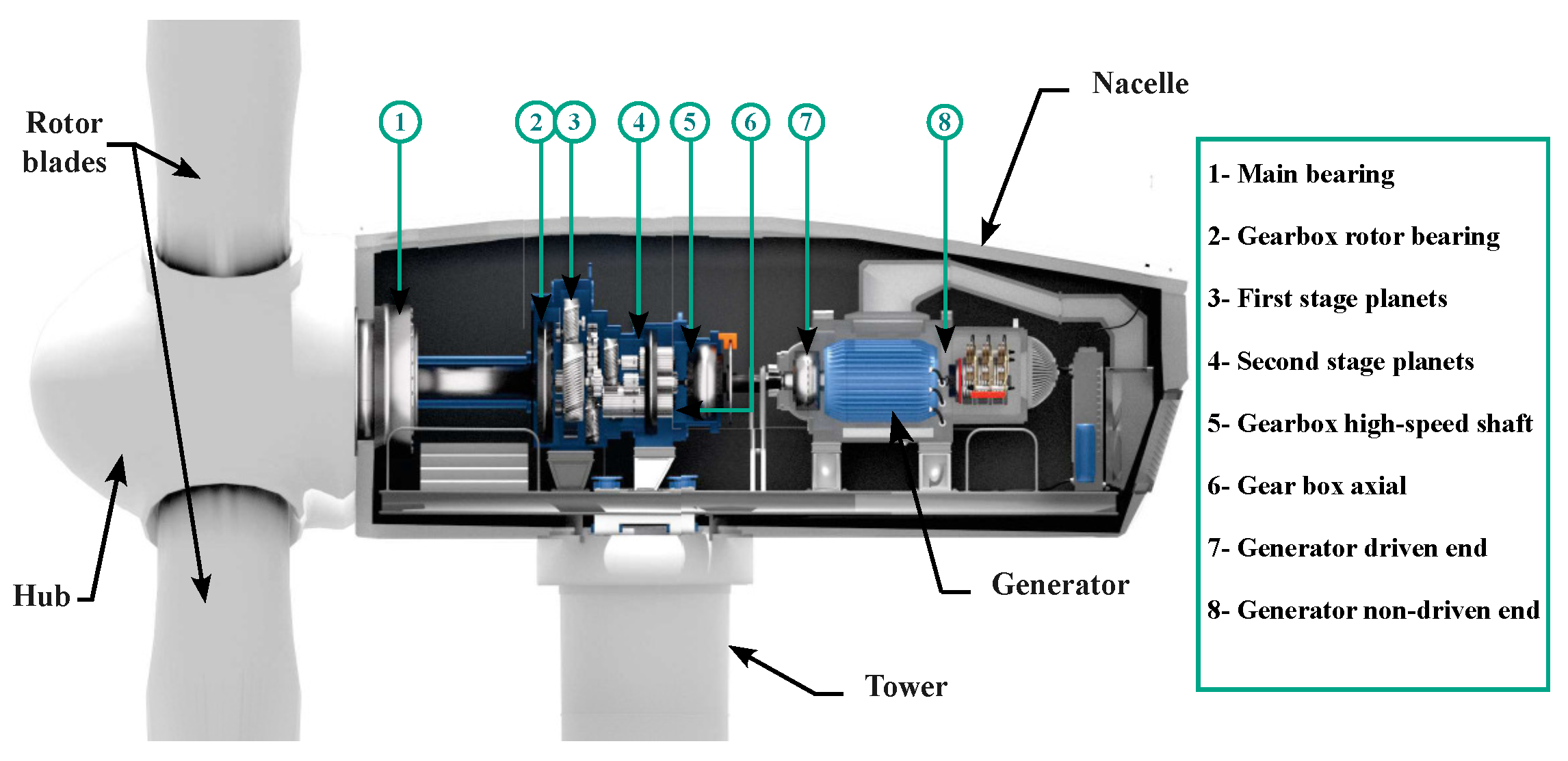
Figure 1. A horizontal axis wind turbine with an enlarged view of the generator and rotational transmission systems [24].
Energies 17 03928 g001
Figure 2. Typical alignment defaults that induce vibration: (a) parallel misalignment, (b) angular misalignment, (c) combined parallel–angular misalignment, and (d) unbalance: (d-1) static unbalance, (d-2) coupled unbalance.
Energies 17 03928 g002
Figure 3. Physical installation and locations of accelerometers installed on the wind turbine: The accelerometer number (AN) with the associated asset annotation [34].
Energies 17 03928 g003
Figure 4. An illustration of the scientific contribution of our article in the context of condition monitoring systems (CMSs) and wind turbine sustainability.
Energies 17 03928 g004
Figure 5. A flowchart illustrating the research question, scientific contribution, and the various topics explored in this study.
Energies 17 03928 g005
Figure 6. The main steps of an LCA issued by the standard ISO 14040.
Energies 17 03928 g006
Figure 7. Comprehensive map of life cycle stages considering system boundaries in the LCA accelerometer.
Energies 17 03928 g007
Figure 8. A schematic illustration of the accelerometer with its different components.
Energies 17 03928 g008
Figure 9. The energy-dispersive X-ray spectroscopy spectra for PZT.
Energies 17 03928 g009
Figure 10. The unique score versus the different part of the accelerometer for the 16 impact categories of Midpoint.
Energies 17 03928 g010
Figure 11. The unique score versus the 16 impact categories for the accelerometer parts.
Energies 17 03928 g011
Figure 12. The unique score versus the 16 impact categories for the copper extraction, transport, energy consumption, and manufacturing process.
Energies 17 03928 g012
Figure 13. The unique score versus the 16 impact categories of the copper material extraction.
Energies 17 03928 g013
Table 1. The different types of accelerometers used for measuring vibrations.
Sensor TypeTemperature RangeSize of the Sensor CasingFrequency ResponseMeasurement RangeSensitivity
PECryo up to >+300 °CVery smallDC to 10 kHz+2 g to 50 × 103 gVery high
IEPE−50 °C to +200 °C, Cryo possiblenormalTypically 0.5 Hz to 10 kHz10 g to 10 × 103 gnormal
MEMS−50 °C to 120 °CnormalDC to 3 kHz0 g to 250 ghigh
Table 2. Characteristics of the accelerometer M603C01 given in the manufacturer’s TDS [62].
PerformanceSI UnitValue
Sensitivity (±10%)mV (m/s2)10.2
Measurement rangem/s2±490
Frequency range (±3 dB)Hz0.5 to 104
Resonant frequencyHz25
Broadband resolution (1 to 104 Hz) μ m/s23434
Non-linearity±1%
Transverse sensitivity≤7%
Table 3. The scope of the LCA of an accelerometer used in wind turbine condition monitoring systems (CMSs).
LCA KeysAccelerometer M603C01
Functional unitOne accelerometer that transmits the vibration signal to the processing unit during ( 1   +   20 % ) × MTBF of the asset
LifespanIt is assumed to be 3 years
System BoundariesCradle to gate: From raw material extraction to manufacturing stage
Method/Normalization/PonderationEuropean, ILCD 2011 Midpoint+ [63]/EC-JRC Global, Equal weighting
Environmental impact categories16 indicators of Midpoint
Table 4. The accelerometer bill of materials (BOM).
ItemDesignationQuantityWeight (g)MaterialManufacturing ProcessSimaPro Database
1Housing149.17Stainless steelMachiningAvailable
2Active material10.27Piezoceramic PZTSinteringNot available
3Screw stud11.71CopperMachiningAvailable
4Capsule10.68TungstenMachiningAvailable
5Electrical connectors10.45CopperExtrusionAvailable
6Integral electronics10.71Cu/Al/Polymer ⋯Electronics processesNot available
7Mass11.51TungstenMachiningAvailable
8Washer10.26EpoxyCutting/drillingAvailable
Table 5. Composition of the mineral part of the PZT given in weight percentage.
PZT Material CompositionWeight %Measured Weight %
Lead Oxide50–7056.31
Zirconium Oxide10–3011.19
Titanium Oxide5–204.89
Niobium Oxide0–100.52
Strontium Oxide0–52.54
Barium Oxide0–53.13
Magnesium Oxide0–50.13
Nickel Oxide0–50.00
Iron Oxide0–50.00
Manganese Oxide0–50.00
Silver0–250.38
Table 6. The Midpoint impact categories calculated in this LCA of the accelerometer.
Impact CategoriesUnityHousingActive Material (PZT)Screw StudElectrical ConnectorsMassCapsule
TotalmPt38.04479.4441320.963894.821568.689489.8220
Climate changemPt0.01490.00320.12480.06610.19880.5869
Ozone depletionmPt0.05840.01460.05180.04990.05370.0237
Human toxicity non-cancer effectsmPt1.37120.3964127.012332.685611.386514.0418
Human toxicity, cancer effectsmPt2.68750.420953.891515.119624.143048.3682
Particulate mattermPt0.03440.00740.68410.20320.24920.4781
Ionizing radiation HHmPt32.78338.195416.218016.085716.41217.6362
Ionizing radiation E (interim)mPt0.00000.00000.00000.00000.00000.0000
Photochemical ozone formationmPt0.00880.00220.21300.06760.10070.1761
AcidificationmPt0.01140.00260.95610.26640.19830.5215
Terrestrial eutrophicationmPt0.00920.00240.21720.07190.11250.1685
Freshwater eutrophicationmPt0.1020.00341.57060.40740.19251.3022
Marine eutrophicationmPt0.01380.00340.14830.04980.06220.1406
Freshwater ecotoxicitymPt0.78470.2373109.802628.272612.154415.5745
Land usemPt0.00000.00000.00050.00020.00020.0001
Water resource depletionmPt0.03570.00900.08190.0809−0.01450.7068
Mineral, fossil and renewable resource depletionmPt0.22140.14599.99121.39463.43980.0967
Disclaimer/Publisher’s Note: The statements, opinions and data contained in all publications are solely those of the individual author(s) and contributor(s) and not of MDPI and/or the editor(s). MDPI and/or the editor(s) disclaim responsibility for any injury to people or property resulting from any ideas, methods, instructions or products referred to in the content.