Article

A Fast State-of-Charge (SOC) Balancing and Current Sharing Control Strategy for Distributed Energy Storage Units in a DC Microgrid

1
School of Electrical and Information Engineering, Yunnan Minzu University, Kunming 650504, China
2
Yunnan Key Laboratory of Unmanned Autonomous System, Kunming 650504, China
*
Author to whom correspondence should be addressed.
Energies 2024, 17(16), 3885; https://doi.org/10.3390/en17163885
Submission received: 16 July 2024 / Revised: 25 July 2024 / Accepted: 2 August 2024 / Published: 6 August 2024

Abstract

:
In isolated operation, DC microgrids require multiple distributed energy storage units (DESUs) to accommodate the variability of distributed generation (DG). The traditional control strategy has the problem of uneven allocation of load current when the line impedance is not matched. As the state-of-charge (SOC) balancing proceeds, the SOC difference gradually decreases, leading to a gradual decrease in the balancing rate. Thus, an improved SOC droop control strategy is introduced in this paper, which uses a combination of power and exponential functions to improve the virtual impedance responsiveness to SOC changes and introduces an adaptive acceleration factor to improve the slow SOC balancing problem. We construct a sparse communication network to achieve information exchange between DESU neighboring units. A global optimization controller employing the consistency algorithm is designed to mitigate the impact of line impedance mismatch on SOC balancing and current allocation. This approach uses a single controller to restore DC bus voltage, effectively reducing control connections and alleviating the communication burden on the system. Lastly, a simulation model of the DC microgrid is developed using MATLAB/Simulink R2021b. The results confirm that the proposed control strategy achieves rapid SOC balancing and the precise allocation of load currents in various complex operational scenarios.

1. Introduction

Renewable energy sources (RESs) are increasingly becoming the mainstream choice in the current global energy transition due to their clean and sustainable nature [1,2]. The widespread adoption of RESs, such as solar and wind power, reduces dependence on finite resources and significantly mitigates greenhouse gas (GHG) emissions, offering crucial opportunities for global climate change mitigation. However, RES faces challenges, notably its inherent instability and intermittency. Solar photovoltaic (PV) and wind power generation are directly influenced by weather conditions, resulting in frequent and unpredictable energy fluctuations within the grid [3]. DC microgrids have emerged as a promising energy system solution to effectively integrate large-scale RES.
DC microgrids optimize energy distribution in generation, transmission, and consumption through DC technology [4]. Unlike traditional AC grids, DC microgrids offer lower energy conversion losses, increased energy utilization efficiency, and superior compatibility with various electronic devices and energy storage systems (ESSs). Usually, ESSs are widely applied in various sectors of modern industrial technology, including marine and railway energy storage systems [5]. However, in DC microgrids, ESSs are crucial for ensuring the stability and reliability of energy supply, as they store surplus electricity to manage the intermittent fluctuations in renewable energy generation [6]. ESSs typically consist of multiple DESUs, which may vary in capacity and SOC due to differences in brands and usage levels. This variation can lead to some DESUs being overcharged or discharged, thereby reducing the ESS’s lifespan. Maintaining balanced SOC levels is crucial for extending the lifespan of ESS and optimizing energy utilization efficiency [7,8,9].
I-U droop control is commonly utilized in DC microgrids to regulate DC/DC converters along the line. This control method achieves equal distribution of ESS load currents without requiring communication and is known for its high stability, flexibility, and plug-and-play nature [10]. Despite its straightforward implementation, droop control introduces virtual impedance into the DC/DC converter circuit, leading to voltage deviations that affect the precise allocation of load output current [11]. Furthermore, droop control does not consider SOC information, making balancing SOC between DESUs impossible.
To achieve SOC balancing, reference [12] proposed an exponential descent control strategy, which changes the virtual impedance based on the SOC difference information. Reference [13] used an SOC balancing strategy based on this strategy, which combines a power function with an exponential function to speed up the SOC balancing process. Reference [14] introduces a method that utilizes the SOC power function to adjust the droop coefficient, facilitating power balancing dynamically. However, it only discusses the SOC balancing during ESS discharge and does not consider the SOC balancing during charging. In reference [15] the droop coefficient varies inversely with the nth order of the SOC, enabling adaptive charging and discharging of DESU. When the system is in the discharged state, the larger the SOC, the more power the DESU releases, thus accelerating the SOC convergence. Reference [16] designs a SOC balancing control strategy, considering different capacities of DESUs. References [12,13,14,15,16] do not account for potential bus voltage deviations that may occur during system operation, reducing the reliability of the system. Reference [17] uses a fuzzy logic system to achieve SOC balancing and stabilize voltage by adjusting the droop coefficient according to the SOC. Reference [18] incorporates variable regulation factors into its SOC-balancing strategy. However, fluctuations in these factors can lead to sudden changes in current output, thereby complicating the maintenance of stable load demand. None of the SOC balancing strategies proposed in references [12,13,14,15,16,17,18] account for the potential impact of line impedance mismatch, which complicates SOC balancing and the allocation of load output current.
Reference [19] combines the inverse tangent function containing droop coefficients with SOC and facilitates the inverse tangent function characteristics to accelerate SOC convergence. It then introduces the virtual rated power compensation term to achieve power-sharing equally and eliminate the effect of line impedance mismatch. Reference [20] introduces an integrator-based unified controller that combines power and voltage to form a state information factor for power sharing and stabilizing the average bus voltage close to the rated value. Reference [21] introduces a state-factor-compensated control strategy integrating current, voltage, and dynamic droop factor information. DESUs are considered with different capacities, and the SOC equalization function is designed with an acceleration factor. Reference [22] details the design of a SOC balancing function alongside the implementation of a power-sharing control link for adaptive output voltage regulation. However, the difference in the capacity of DESUs is not considered.
This paper introduces a coordinated control strategy for multiple DESUs to eliminate the effect of line impedance mismatches and achieve rapid SOC balancing. Table 1 compares this method with other SOC balance control methods. It provides several critical contributions compared to existing methods. To address the capacity differences among DESUs, a nested power and exponential function is employed to correlate the rated capacity with SOC, enabling adaptive adjustment of virtual impedance based on SOC. Two convergence coefficients and an adaptive acceleration factor are introduced to expedite SOC balancing. A global optimization controller is proposed to mitigate line impedance effects and ensure reliable bus voltage quality. This controller utilizes a single integrator to maintain constant bus voltage stability and achieve precise load current distribution. Each DESU communicates exclusively with neighboring units through a sparse communication network and employs a dynamic consensus algorithm to gather global average state information. This approach effectively minimizes communication overhead and system-wide control dependencies.

2. Isolated DC Microgrid Structures and the Analysis of Conventional Droop Control

This paper investigates an isolated DC microgrid consisting of PV and wind power generation units, AC and DC loads, and an ESS [23]. These elements are interconnected through DC/DC converters to a common DC bus, as depicted in Figure 1.
PV and wind power units usually employ maximum power point tracking (MPPT) techniques to maximize RES and improve energy efficiency [24]. In DC microgrids, ESS is crucial in equalizing the difference between supply and demand, enhancing the system’s stability and reliability, and providing backup power in contingencies. Maintaining the SOC balancing in the ESS ensures that the charging and discharging levels of individual DESUs remain relatively consistent. This approach helps prevent damage and energy loss from overcharging and discharging, extending the service life and enhancing performance [25]. Additionally, SOC balancing enhances the reliability and stability of the energy storage system, enabling adequate power support under diverse operating conditions.
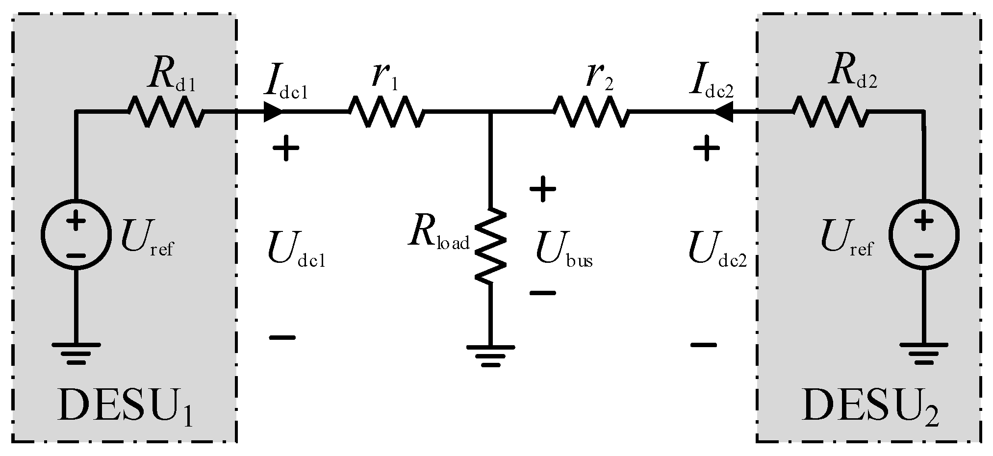
In DC microgrid systems, I-U droop control is often used. It regulates the voltage levels within the microgrid to ensure voltage stability between individual connected devices and power sources. The equivalent structure of two DESUs in parallel is shown in Figure 2. The expression is as follows:
U dc 1 = U ref R d 1 I dc 1
where Udc1 is the DC/DC converter output voltage of DEUS1, Uref is the bus voltage rating, Rd1 is the virtual impedance of DEUS1, Idc1 is the DC/DC converter output current of DEUS1, and Rload is the load impedance.
Considering the line impedance and assuming that the DC/DC converter is ideal and the converter output voltage follows the reference value, the ratio of DESU1 and DESU2 output currents can be obtained:
I dc 1 I dc 2 = R d 2 + r 2 R d 1 + r 1
The real-time SOC acquisition of DESUi is carried out using the Cullen counting method:
S i = S i 0 η C b i I dc i d t
where Si0 is the initial SOC of DESUi; η is the ratio of the DC/DC converter output voltage Udci of DESUi to the battery voltage Ui, and Cbi is the DESUi capacity. The derivation of Equation (3) leads to
S i = η C b i I dc i
Substituting into Equation (2) yields
S 1 S 2 = C b 2 ( r 2 + R d 2 ) C b 1 ( r 1 + R d 1 )
From Equation (5), the DESU’s SOC balancing effect in a DC microgrid is related to the line impedance r, the virtual impedance Rd, and the capacity Cb [26]. The adaptive adjustment of virtual impedance is necessary to achieve rapid SOC balancing and address issues such as line impedance mismatch and variations in DESU capacity due to repeated charging and discharging.
Figure 3 shows the overall control block diagram for DESUi, which this paper verified using multiple DESUs in parallel.

3. Improved Droop Control Strategy

3.1. Dynamic Consistency Algorithm

This paper considers each DESU as intelligent within a multi-agent system (MAS). The DESUs are interconnected through a communication network, depicted by the communication topology in Figure 4. The system connectivity graph is represented as an undirected graph G (V, E), where V = {1, 2, ..., n} denotes the set of nodes and E = {(i, j)∈V × V} denotes the set of edges. Each intelligence only needs to interact with its neighboring units to exchange state information and attain average system state information. The classical consistency algorithm can be expressed as
x avg i = u i t
u i t = j N i a i j x i t x j t
where xi and xj are the state variables of nodes i and j, respectively; aij is the neighborhood matrix coefficients; (i,j) ∈ E, aij > 0, and otherwise aij = 0; and Ni represents the set of neighbors of node i. The Laplacian matrix L = (lij) N × N of the undirected graph G is
l i j = a i j i j j = 1 , j i a i j i = j
To enhance the algorithm’s convergence speed and to meet the stability requirements of the DC microgrid operation, reference [21] presented an improved dynamic consistency algorithm with the following expression:
x avg i ( k + 1 ) = x i + j N i a i j D i j ( k + 1 ) D i j ( k + 1 ) = D i j ( k ) + δ i j x avg j ( k ) x avg i ( k )
where xavgi (k + 1) is the estimation of the global average state information of the ith node after the k + 1st iteration, which is utilized to derive the global mean data estimate in this paper; Dij (k + 1) is the cumulative difference between nodes i and j at the k + 1st iteration, with an initial iteration value of 0; δij denotes the state of the communication connection between DESUi and DESUj, where δij = 1 denotes that there is a communication connection, and δij = 0 means there is no communication connection; and aij is the link weight, and its expression is as follows:
a i j = 2 λ 1 ( L ) + λ M 1 ( L )
where λi (L) is the ith largest eigenvalue in the Laplace matrix L and M is the total number of nodes. The Laplace matrix L can be expressed as
L = d 1 l 12 l 1 N l 21 d 2 l 2 N l N 1 l N 2 d N
where d is the degree of node I, and lij = −1 when nodes i and j are neighboring nodes, and otherwise, lij = 0.
All intelligent agents iteratively calculate and adjust the values of state variables according to consistency algorithms to make the state variables of the entire system tend towards consistency and ultimately achieve convergence. It reduces system communication pressure and avoids adverse factors such as single-point failures, enabling system control to operate stably and flexibly.

3.2. SOC Balancing Control Strategy with an Adaptive Acceleration Factor

For fast SOC balancing, reference [13] proposes a power function combined with an exponential function for droop control with the following virtual impedance representation:
R d i S i = R d 0 exp p S i n S a n I dc i > 0 R d 0 exp p S i n S a n I dc i < 0
S a = i = 1 N S i N
where Rd0 is the initial value of virtual impedance, p is the acceleration factor, and Sa is the average SOC. The control proposed in [13] has a better balancing effect, but SOC balancing is slow. Moreover, SOC balancing cannot be achieved in the presence of a capacity difference and mismatched line resistance.
R d i S i = R d 0 C b i 1 + m exp sgn I dc i p k i S i n S a n
sgn ( x ) = 1 x > 0 0 x = 0 1 x < 0
where the sign function sgn(x) denotes the charging and discharging state of the system; m and p are convergence coefficients; and ki is the acceleration factor, which is expressed as follows:
k i = 1 α S i n S a n + d
where α, d are adjustment factors, α > 1, 0 < d < 1.
Combined with Equation (1), Equation (3) can be expressed as
S i = S i 0 η C b i U ref U dc i R d i dt
To validate the proposed SOC balancing function, the output voltage of the DESU’s DC/DC converter is assumed to track the reference value, with the discharge state considered as an example. Combining with Equation (14), the SOC of the DESUi can be expressed as
S i = S i 0 η U ref U dc R d 0 exp p k i S i n S a n exp p k i S i n S a n + m dt
The derivation of Equation (18) is
S i = η U ref U dc R d 0 exp p k i S i n S a n exp p k i S i n S a n + m
Substituting the first-order Taylor expansion of ex = 1 + x,
S i = η U ref U dc R d 0 1 + p k i S i n S a n 1 + p k i S i n S a n + m
From Equation (20), the SOC derivative deviation of neighboring DESU is given as
Δ S i j = η U ref U dc R d 0 1 + p k j S j n S a n 1 + p k j S j n S a n + m 1 + p k i S i n S a n 1 + p k i S i n S a n + m
Equation (21) is replaced with the following:
Δ S i j = η U ref U dc R d 0 y j y i
y = x x + m
The function y = x/(x + m) is positive for x > 0 and exhibits an increasing trend. When Si0 > Sj0, Si0 > Sa > Sj0, ΔS′ij < 0, Rdi < Rdj, the discharge current of DESUi is higher, and the rate of SOC decrease is faster. When Si0 < Sj0, Si0 < Sa < Sj0, ΔSij > 0, Rdi > Rdj, the discharge current of DESUj is more extensive, and the rate of SOC decrease is faster. As the balancing process continues, DESU’s SOC will tend to be consistent. Likewise, SOC balancing can also be achieved during the charging process.
Set the SOC balancing error factor μ:
S a S i μ
when Equation (24) holds, the SOC can be considered to have reached balancing.
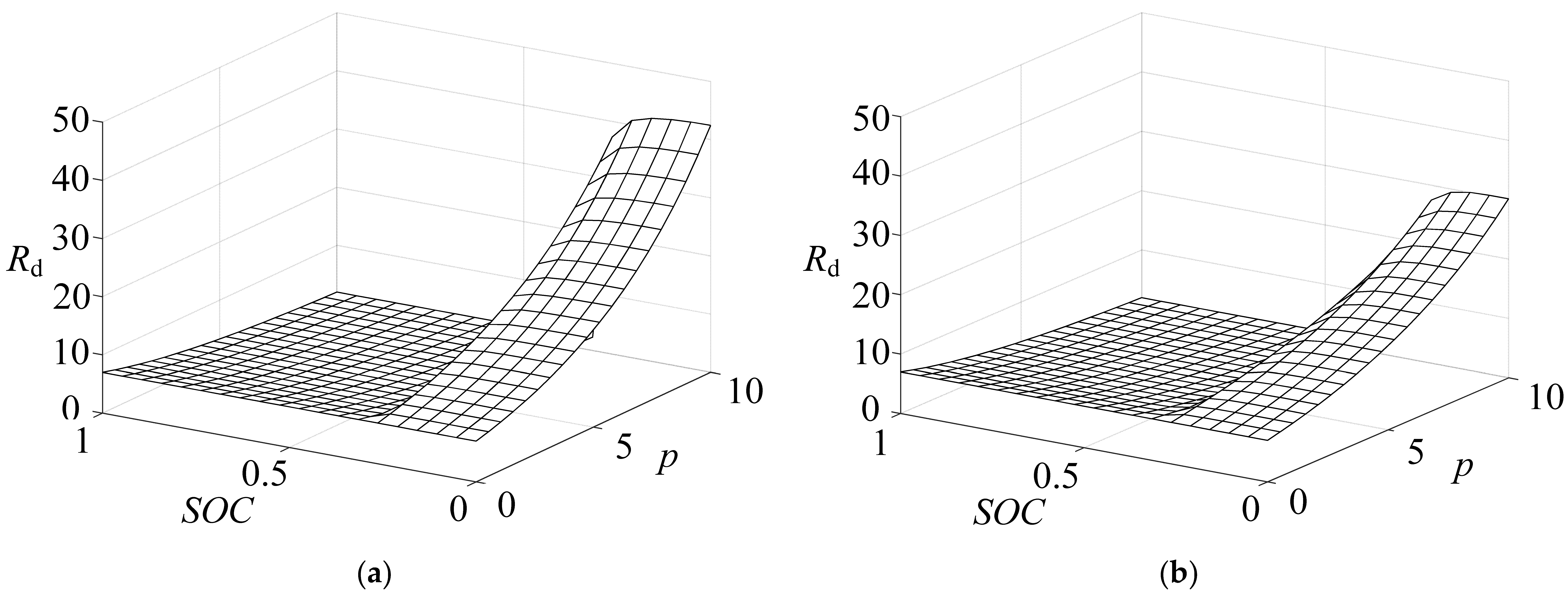
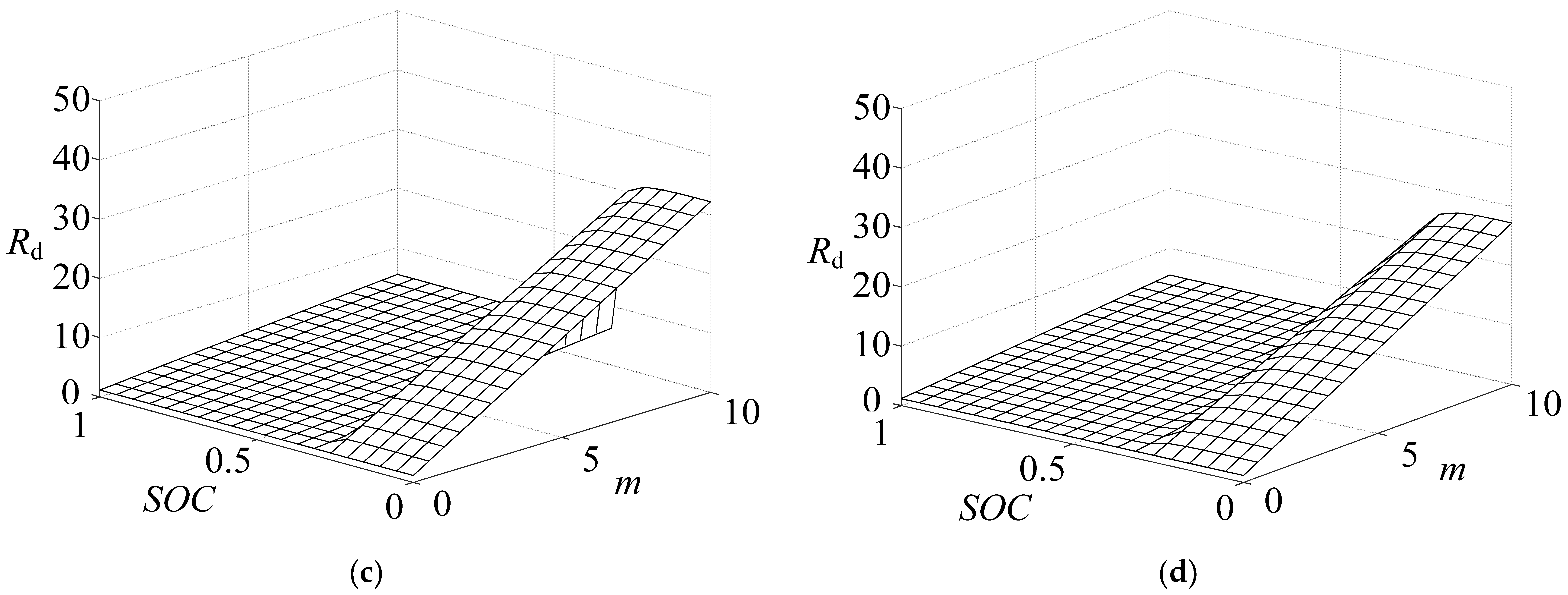
Figure 5a,b illustrate that with m = 5, the virtual impedance Rd increases steadily as p increases when S < Sa, while this trend diminishes with increasing n. Conversely, Rd decreases with higher values of p and n when S > Sa. Figure 5c,d show consistent trends with Figure 5a,b for increasing values of m and n when S < Sa, with p set to 5. For S > Sa, Rd increases with m and decreases with n. Increasing the convergence coefficients m and p enhances SOC balancing speed; when p and m are more significant than 5, the convergence coefficient p-value for the SOC balancing impact is more significant than m. However, overly large m and p values can lead to heightened system fluctuations, risking a current output exceeding the limits. Larger n values reduce the SOC balancing speed. This study opts for m = 5, p = 6, and n = 2 to ensure the requirements of fast SOC balancing and system stability.
The adaptive acceleration factor ki is designed to address the issue of slow balancing speed during the late stages of SOC balancing in the system. The regulation coefficients α and d values in the speedup factor ki are also crucial. During the later stages of SOC balancing, when the SOC difference among DESU tends to 0, α|SnSna| in the speedup factor ki also gradually tends to 0. The d should be less than 1 to expedite the late stage of SOC balancing. The adaptive increase in the speedup factor improves the slow balancing speed of a slight SOC difference, but d is too small, which affects the accuracy of the load current allocation in the line. In the pre-SOC balancing stage, the SOC differences among DESU are significant, and to avoid an enormous impact of d on the SOC balancing effect, α|SnSna| should be much larger than d. When m = 5, p = 6, and n = 2, Figure 6 shows the impact of different values of α and d on Rd, respectively.
Figure 6a shows the variation in the virtual impedance Rd concerning SnSna for different values of α at d = 0.1. The SOC balancing speed can be adjusted by increasing α. Moreover, it can prevent the risk of current overrun due to the significant difference in the SOC of each DESU during the balancing process. As seen from Figure 6b, d can improve the problem of slow SOC balancing in the late stage of balancing. However, a value of d that is too small is also prone to cause significant fluctuations in the system, thus affecting the stability of system operation. In summary, this study selects parameters based on theoretical analysis and extensive experimental results to achieve rapid SOC balancing and ensure system stability: m = 5, p = 6, n = 2, α = 4, d = 0.01.

3.3. Global Optimisation Controller

In the DC microgrid, line impedance mismatch significantly impacts the system’s operational performance, slowing down the SOC balancing rate and impacting the precise distribution of load currents. Moreover, the droop control mechanism decreases the bus voltage, further impacting the system’s stability and efficiency [27]. This paper proposes a multi-objective global optimization controller to address these issues.
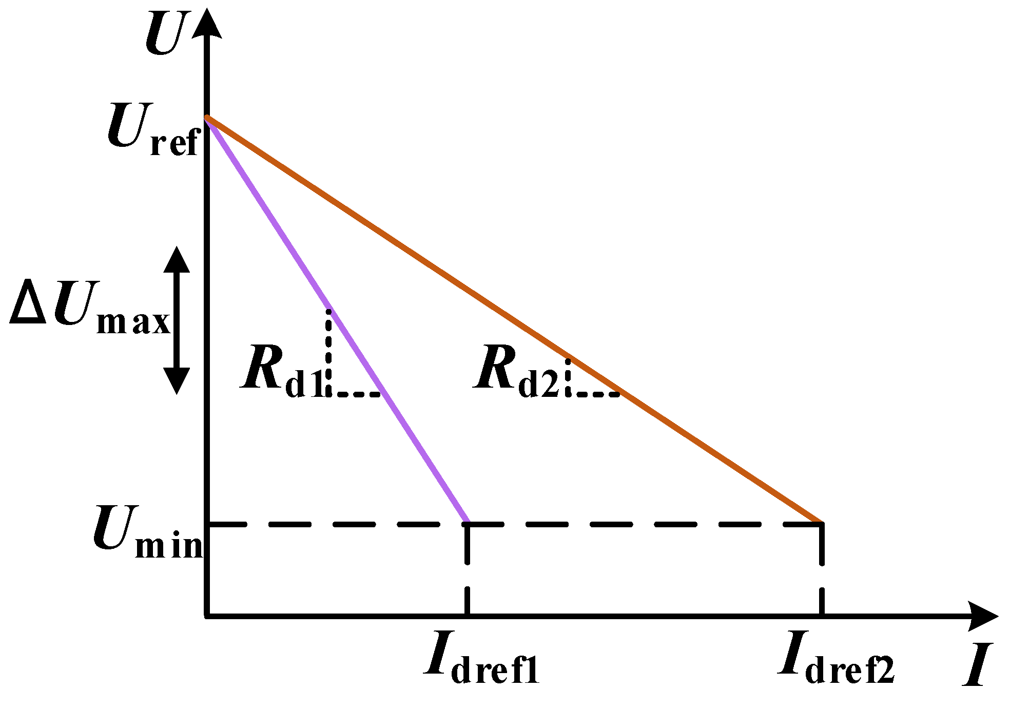
As shown in Figure 7, the virtual rated current value can be obtained from the maximum voltage deviation and the virtual impedance [28].
I dref i = Δ U max R d i
where Idrefi is the virtual rated current value and Umax is the maximum bus voltage deviation.
For illustrative purposes, gi and ga are introduced and defined as follows:
g i = I dc i I dref i
g a = i = 1 n g i n
g 1 = g 2 = = g n
when Equation (28) is satisfied, the effect of mismatched line impedance can be eliminated. We define the current compensation factor y1 as
y 1 = b 1 g a g i
where b1 is the current compensation adjustment factor.
Implementing the droop control method results in standard DC bus voltage excursions. Voltage compensation must be introduced to maintain unaffected system operation despite excessive voltage deviation. The average bus voltage Udca of DESU is
U dca = i = 1 N U dc i N
We define the voltage compensation factor y2 as
y 2 = b 2 U ref U dca
where b2 is the voltage compensation adjustment factor.
The global optimization controller is designed as follows:
Δ U i = K u i y 1 + y 2 dt
where Kui is the integrator control coefficient.
Considering the convergence of the integrator, one obtains
I dc i I dc j = C b i C b j
U ref = U dca
This multi-objective controller effectively compensates for the adverse effects of line impedance by introducing a mechanism that combines compensation factors. An integrator can simultaneously process and adjust the compensation factor to achieve SOC balancing, load current distribution, and bus voltage restoration. This approach not only improves the system’s response speed and load regulation capability but also significantly improves the stability of the DC bus voltage. Finally, the SOC balancing strategy proposed in this paper is denoted as
U ref i = U ref R d i S i I dc i + Δ u i

4. Stability Analysis

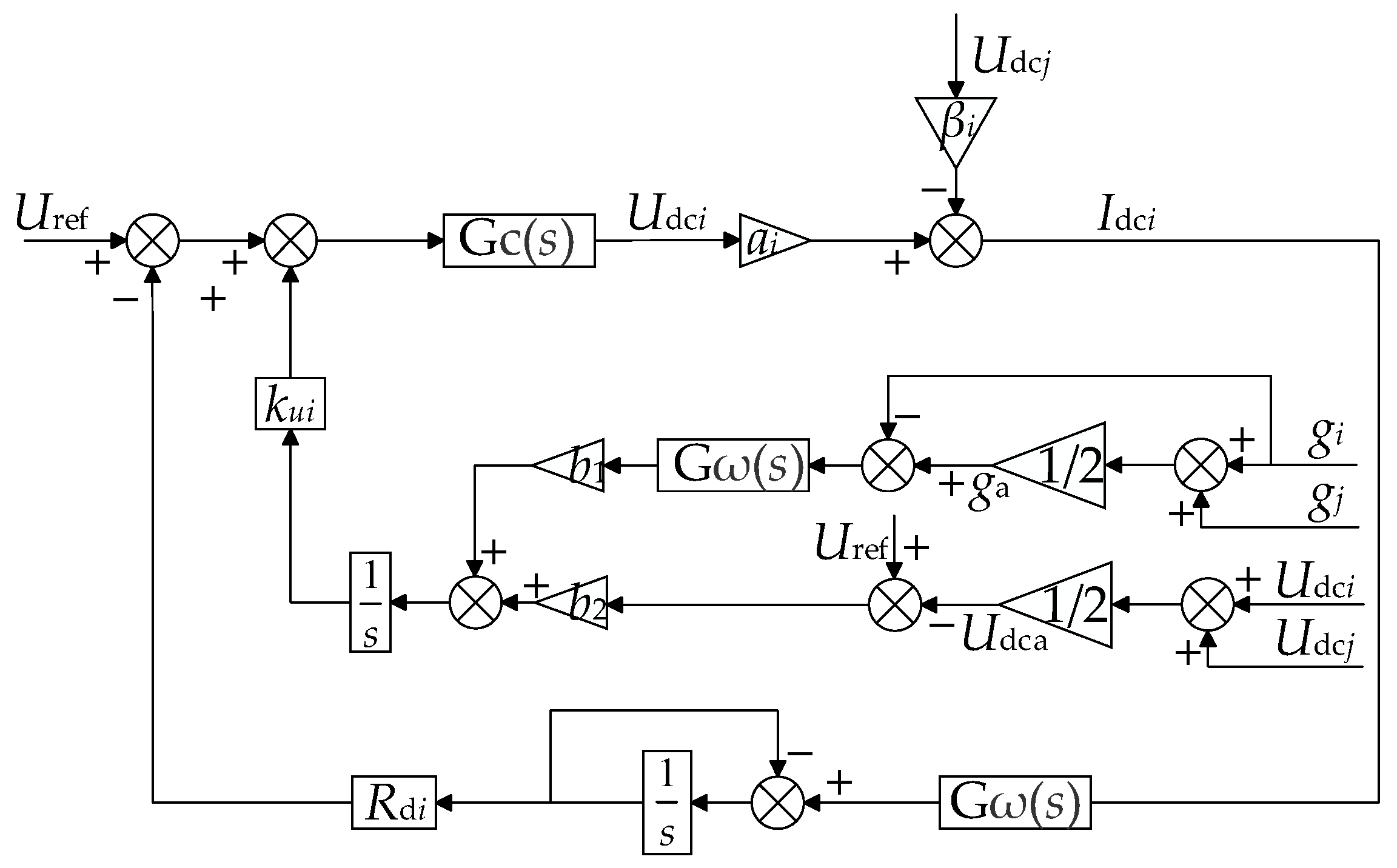
Applying the control strategy outlined in this paper, an operational stability analysis of an isolated DC microgrid system using two parallel DESUs of equal capacity is conducted. Figure 8 illustrates the equivalent model used for stability analysis.
The SOC estimation process can be equivalent to an inertia process, and its transfer function is as follows:
Ge ( s ) = 1 s + 1
The transfer function of the current low-pass filtering link is expressed as follows:
G ω ( s ) = ω c s + ω c
where ωc represents the cut-off frequency of the low-pass filtering link.
Gc(s) is the closed-loop voltage transfer function, expressed as follows:
G C ( s ) = 1 τ s + 1
where τ is the time constant of the switching action, and its value is approximated as 0, so Gc(s) ≈ 1.
From Figure 8, it is evident that the output voltage expression is
U dc 1 = G C ( s ) U ref I dc 1 R d 1 G ω ( s ) G e ( s ) + G C ( s ) k u i s b 1 G ω ( s ) g a g 1 + b 2 U ref U dca
U dc 2 = G C ( s ) U ref I dc 2 R d 2 G ω ( s ) G e ( s ) + G C ( s ) k u i s b 1 G ω ( s ) g a g 2 + b 2 U ref U dca
The expression for the output current is given by
I dc 1 = a 1 U dc 1 β U dc 2 I dc 2 = a 2 U dc 2 β U dc 1
a 1 = r 2 + R load r 1 r 2 + r 1 R load + r 2 R load a 2 = r 1 + R load r 1 r 2 + r 1 R load + r 2 R load β = R load r 1 r 2 + r 1 R load + r 2 R load
Without considering the communication delay, the characteristic equations of the system state can be obtained by combining Equations (24)–(26) and (35)–(40), which are expressed as follows:
B s 3 + C s 2 + Ds + E = 0
where
B = 2 C = 2 ω C + 1 + k ui b 2 D = 2 1 + a 1 R d 1 ω C + k ui b 2 1 + ω C E = b 2 k ui ω C
By substituting data from Table 2 into the characteristic equations, the root trajectory plots of virtual resistance, cut-off frequency, line impedance, and load impedance can be obtained, as shown in Figure 9.
Figure 9a,b indicate that changes in virtual impedance and cut-off frequency significantly affect system stability. Considering bus voltage offset and current allocation accuracy, the virtual impedance must remain within an optimal range. Similarly, the cut-off frequency selection should consider the system’s sampling frequency and the component parameters. Figure 9c,d illustrate that line and load impedance variations influence system stability. Nonetheless, the system’s closed-loop poles consistently reside in the left half-plane, affirming that the proposed control strategy maintains robust system stability.

5. Simulation Results

To validate the validity and reliability of the proposed control strategy, a model of an islanded DC microgrid, consisting of three groups of parallel DESUs and one group of PV-generating units, is constructed using MATLAB/Simulink software. The PV-generating unit is in MPPT mode, and the three groups of DESUs are connected to the DC bus through DC/DC converters using batteries. The simulation mainly verifies whether the proposed control strategy can achieve a fast balancing of SOC, accurate distribution of load current according to capacity, and stability of bus voltage under different complex operating conditions. The simulation parameters are detailed in Table 2.

5.1. Case 1: Normal Charging Ignoring Line Resistance

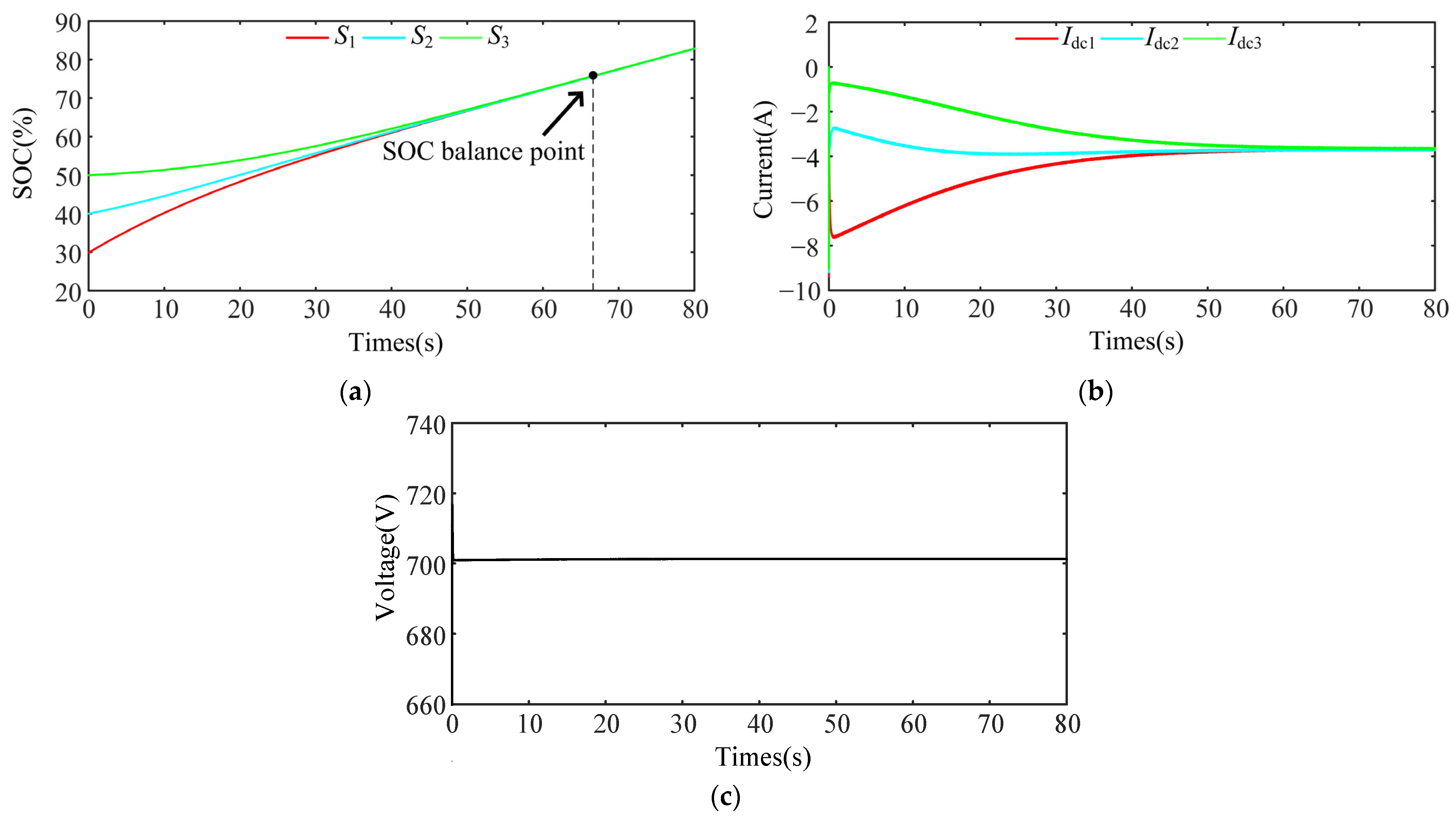
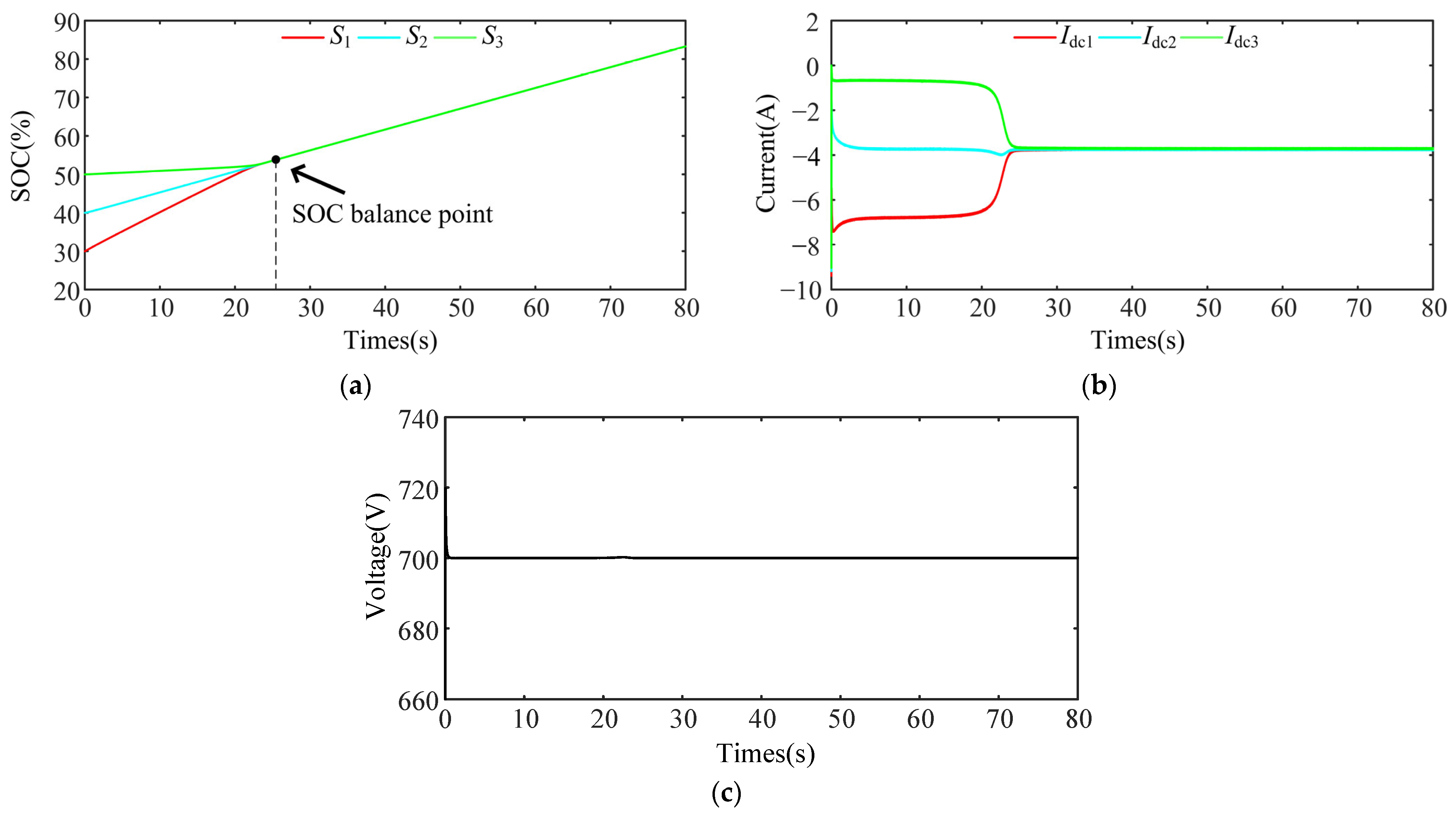
Normal charging is carried out while ignoring the line impedance. The paper compares the proposed control strategy with ref. [13] to validate its ability to achieve rapid SOC balancing, accurate load current distribution based on DESU capacity, and stable bus voltage. The simulation results are depicted in Figure 10 and Figure 11. The SOCs at the initial moments are 30%, 40%, and 50%; the capacity Cb is the same, all are 0.3 Ah; the load power Pd is 891 W; the PV output power Pf is 8 kW.
Figure 10a and Figure 11a demonstrate that the SOC balancing speed under the control strategy presented in this paper is notably superior to that of the strategy proposed in [13]. At the beginning of the system operation, due to the initial moment, S1 is the lowest; it mainly bears the charging power, rises the fastest, and has the most significant charging current. As the balancing process progresses, the SOC difference between DESUs diminishes gradually. The control strategy proposed in [13] exhibits a slow SOC balancing speed, finally achieving balancing at 68 s. In contrast, with the control strategy outlined in this paper, the presence of an adaptive acceleration factor serves to amplify the SOC difference among DESUs as it decreases gradually. This accelerates the SOC balancing process, achieving balancing in just 25 s. Figure 10b and Figure 11b illustrate that once SOC balancing is achieved, both the control strategy from [13] and the strategy proposed in this paper allocate output current based on DESU capacity. However, this paper’s output current fluctuates and deviates less. Figure 10c and Figure 11c show that the bus voltage of [13] has been higher than the rated value because no bus voltage restoration measures have been added. In this paper, the bus voltage has been continuously stabilized at the rated value of 700 V.

5.2. Case 2: Normal Discharge with Line Resistance Mismatch

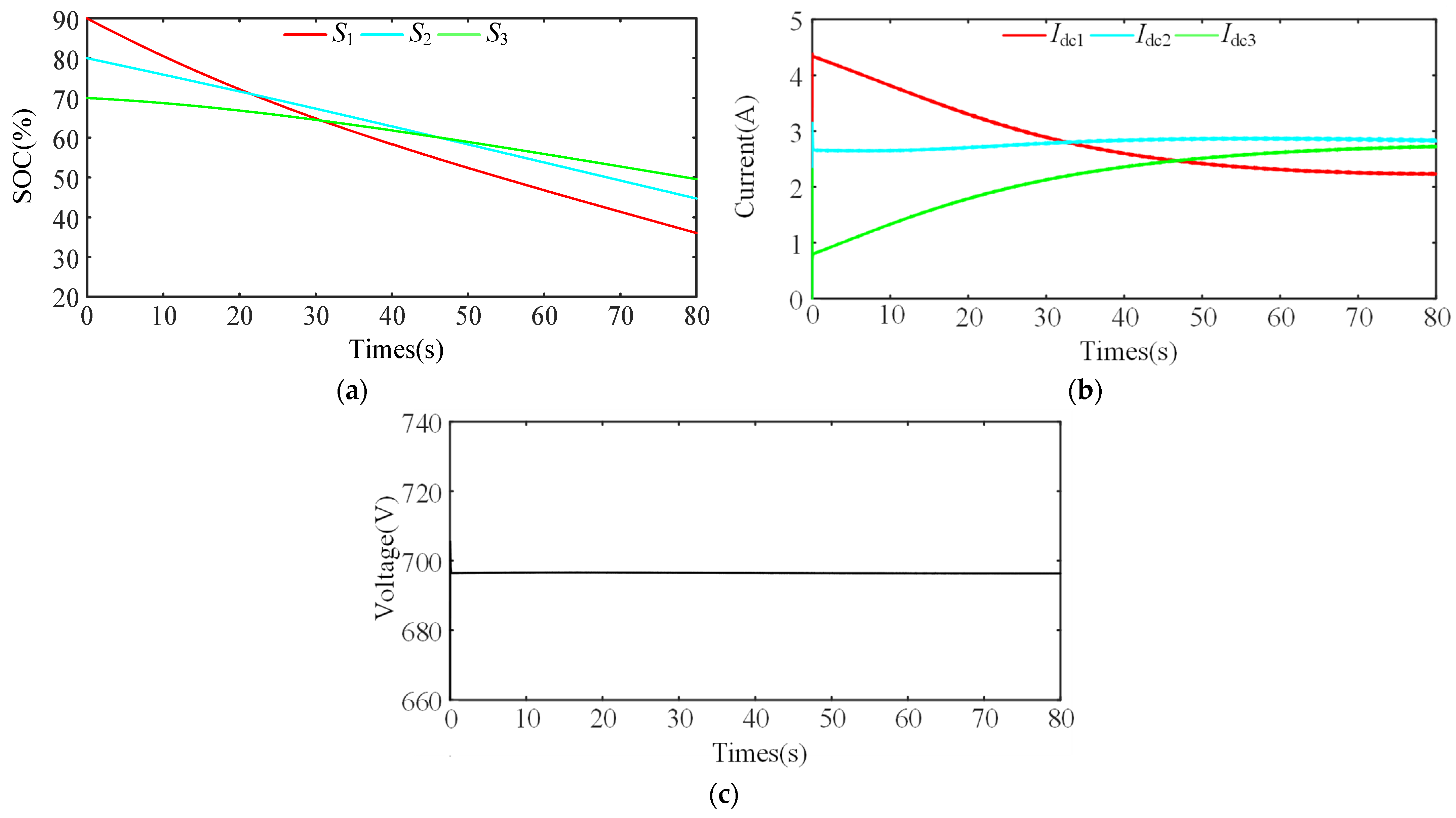
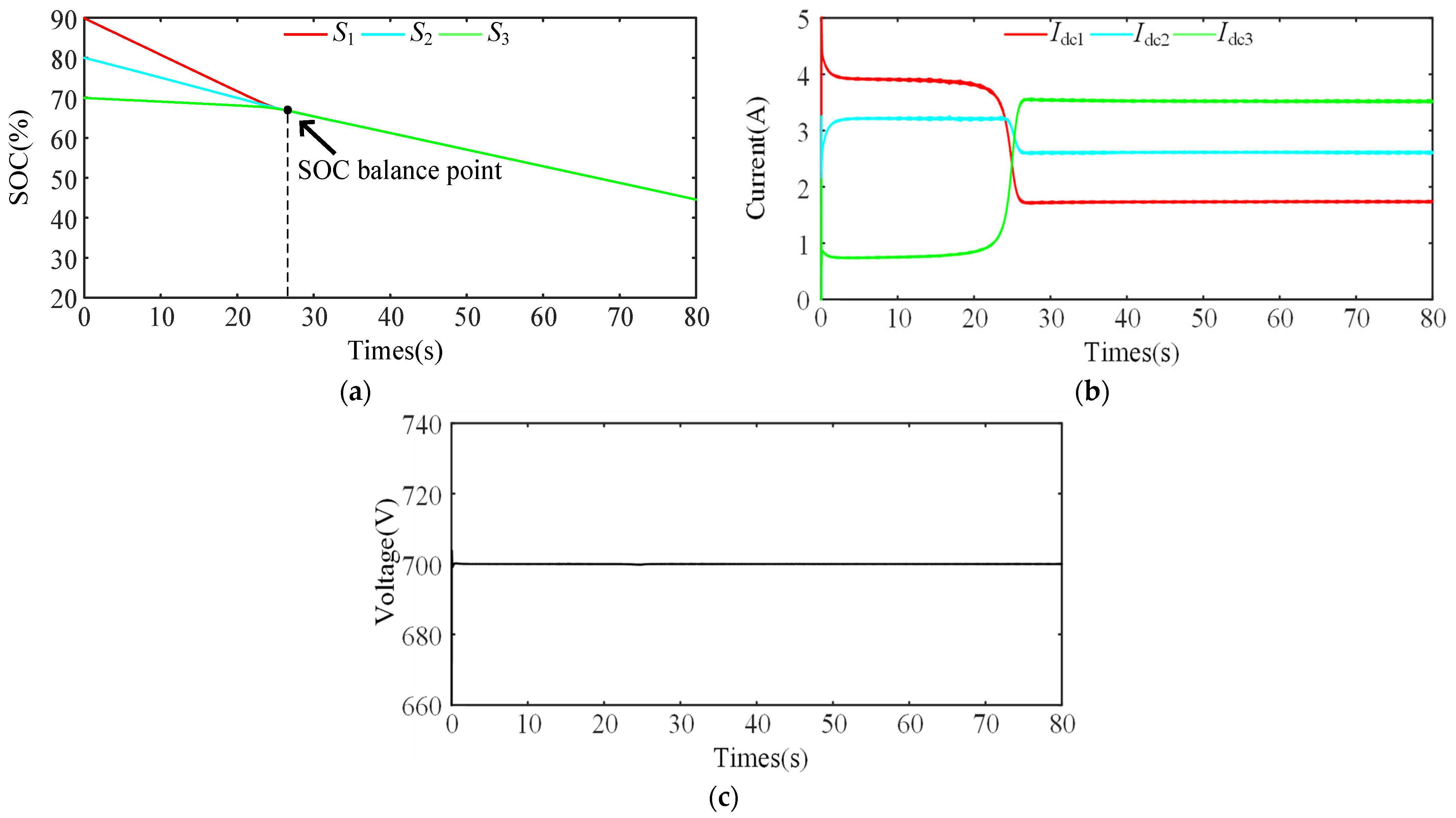
DESUs are discharged normally with mismatched line impedance and unequal DESU capacity. The strategy introduced in this paper is contrasted with that of ref. [13] to assess its capability in achieving rapid SOC balancing, precise load current distribution based on DESU capacity, and stable bus voltage. Simulation outcomes are depicted in Figure 12 and Figure 13. The initial moments of the SOC are 90%, 80%, and 70%, respectively, and the capacities of Cb are 0.2, 0.3 and 0.4 Ah, respectively. The load power Pd is 6.125 kW, and the PV output power Pf is 576 W.
From Figure 12a,b and Figure 13a,b, it is evident that when confronted with line impedance mismatch and DESUs of unequal capacities, the control strategy advocated in ref. [13] does not meet the objectives of SOC balancing and precise current allocation. In this paper, the SOC achieves fast balancing under the control strategy, overcoming the effect of line impedance mismatch. The output current is accurately distributed based on a capacity ratio of 2:3:4. Figure 12c and Figure 13c show that the bus voltage in reference [13] falls below its rated value. Under the strategy proposed in this paper, the bus voltage has been continuously stabilized at the rated value of 700 V, ensuring the power system’s reliable and stable operation.

5.3. Case 3: Load Change

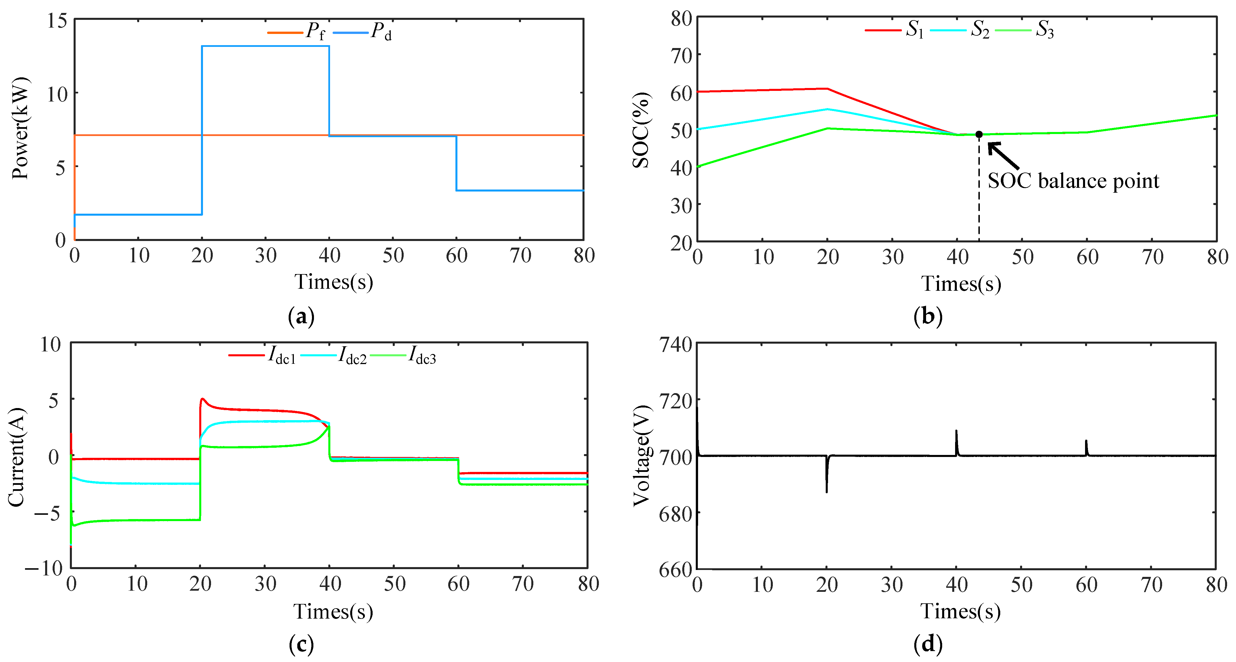
The working condition mainly verifies whether the strategy proposed in this paper achieves rapid switching between charging and discharging states, quick SOC balancing, and precise load current distribution amid frequent load changes. The simulation results are depicted in Figure 14. The initial moments of the SOC are 60%, 50%, and 40%; the capacity Cb is 0.2, 0.3 and 0.4 Ah; the changes in the load power Pd are shown in Figure 14a; and the PV power Pf is 7.1 kW.
From Figure 14a–c, it is evident that the initial load power Pd is 1.7 kW, which is less than the output power Pf of the PV-generating units, indicating that the system is in the charging state. At 20 s, the load power Pf abruptly surged to 13.14 kW, which was insufficient for the PV-generating units to maintain the power demand, and the DESUs were discharged. During this process, the SOC balancing trend is unaffected and is always in the convergence state. At 40 s, the load power Pf mutates slightly lower than the PV output power Pd, and the system is charging, but the DESU charge current is small. At 43 s, the system SOC reaches the balancing requirement. The output current is accurately allocated based on the capacity ratio 2:3:4 among the DESUs. At 60 s, the load power Pf falls to 3.34 kW. Despite the increase in charging current, the current distribution remains unaffected and remains accurately maintained as per the ratio, ensuring the SOC remains efficiently balanced. Figure 14d illustrates that the DC bus voltage fluctuates in response to sudden load changes. These fluctuations remain within a safe range, and the bus voltage swiftly returns to 700 V following a brief adjustment period.

5.4. Case 4: Failure of PV-Generating Units and Frequent Load Switching

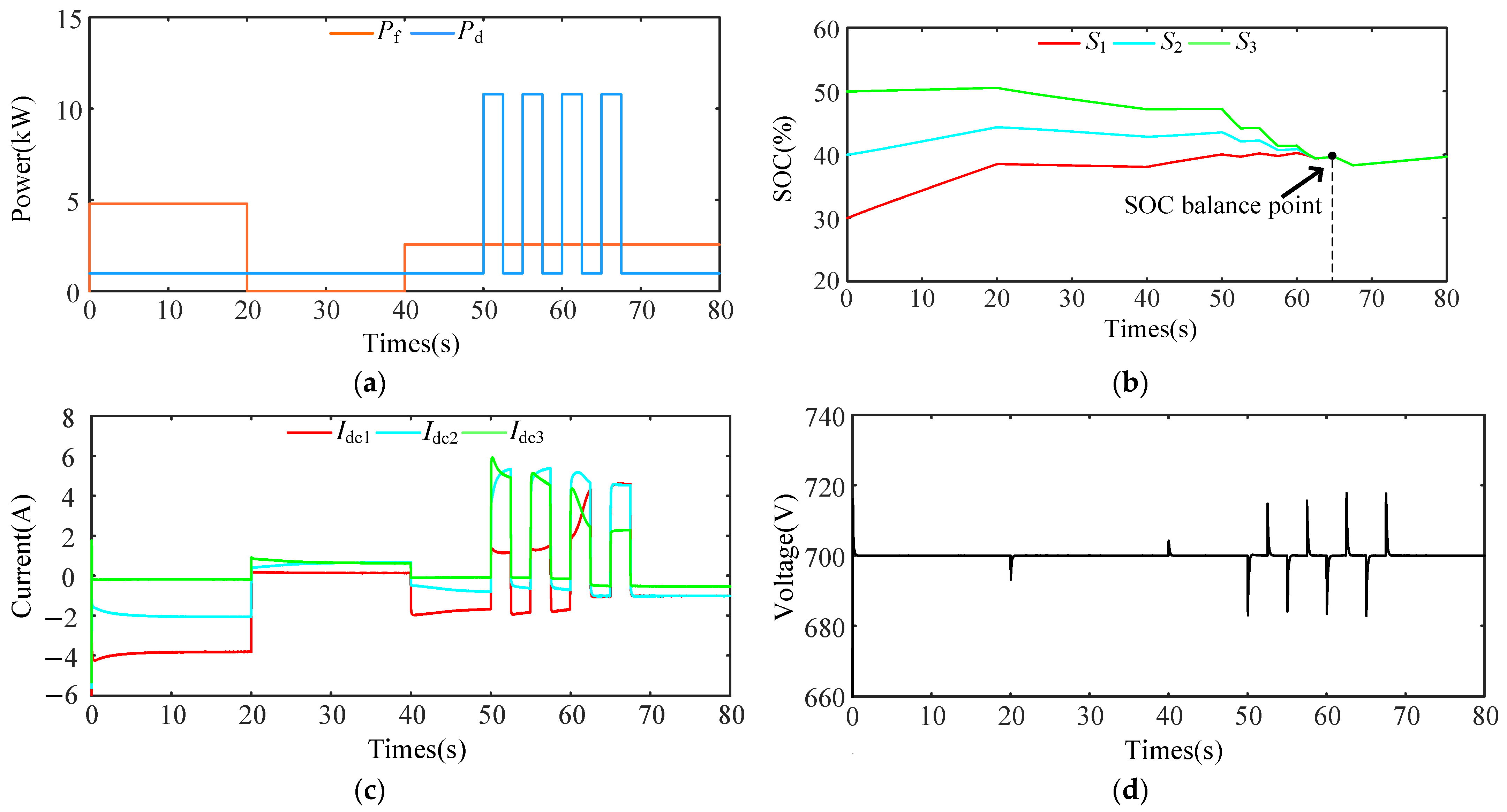
This scenario primarily tests whether the strategy proposed in this paper achieves rapid SOC balancing, accurate load current distribution, and sustained bus voltage stability amidst PV unit failures and frequent heavy load switching. The simulation results are depicted in Figure 15. The initial moments of the SOC are 30%, 40%, and 50%, and the capacity Cb is 0.4, 0.4, and 0.2 Ah. Figure 15a depicts the variations in load power Pd and PV output power Pf.
Figure 15a–c show that at the initial moment, the load power Pd is 985 W and the output power Pf of the PV generation unit is 4.8 kW, indicating that the system is in the charging state. At 20 s, the PV units are shut down due to a fault, the DESUs take up the load demand, and the system transitions from charging to discharging. At 40 s, the PV unit restarts, but the output power Pf is lower than the initial moment, only 2.56 kW, and the system reverts to the charging state. At 50 s, frequent heavy load switching occurs, resulting in frequent sudden increases in load power to 10.78 kW, and the system changes frequently in the charging and discharging states, during which the SOC balancing is always unaffected and maintains efficient balancing capability. At 65 s, the system achieves SOC balancing, and subsequent load changes do not impact the balancing effect and current allocation accuracy. The output current maintains the capacity ratio of 2:2:1 for accurate allocation. Figure 15d depicts fluctuations in the DC bus voltage occurring during PV unit failures and load-switching events. After a short adjustment period, the bus voltage quickly recovers to 700 V and stabilizes at 700 V.

5.5. Case 5: Validation of System Scalability

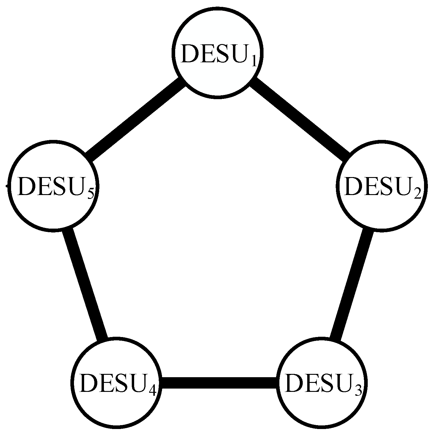
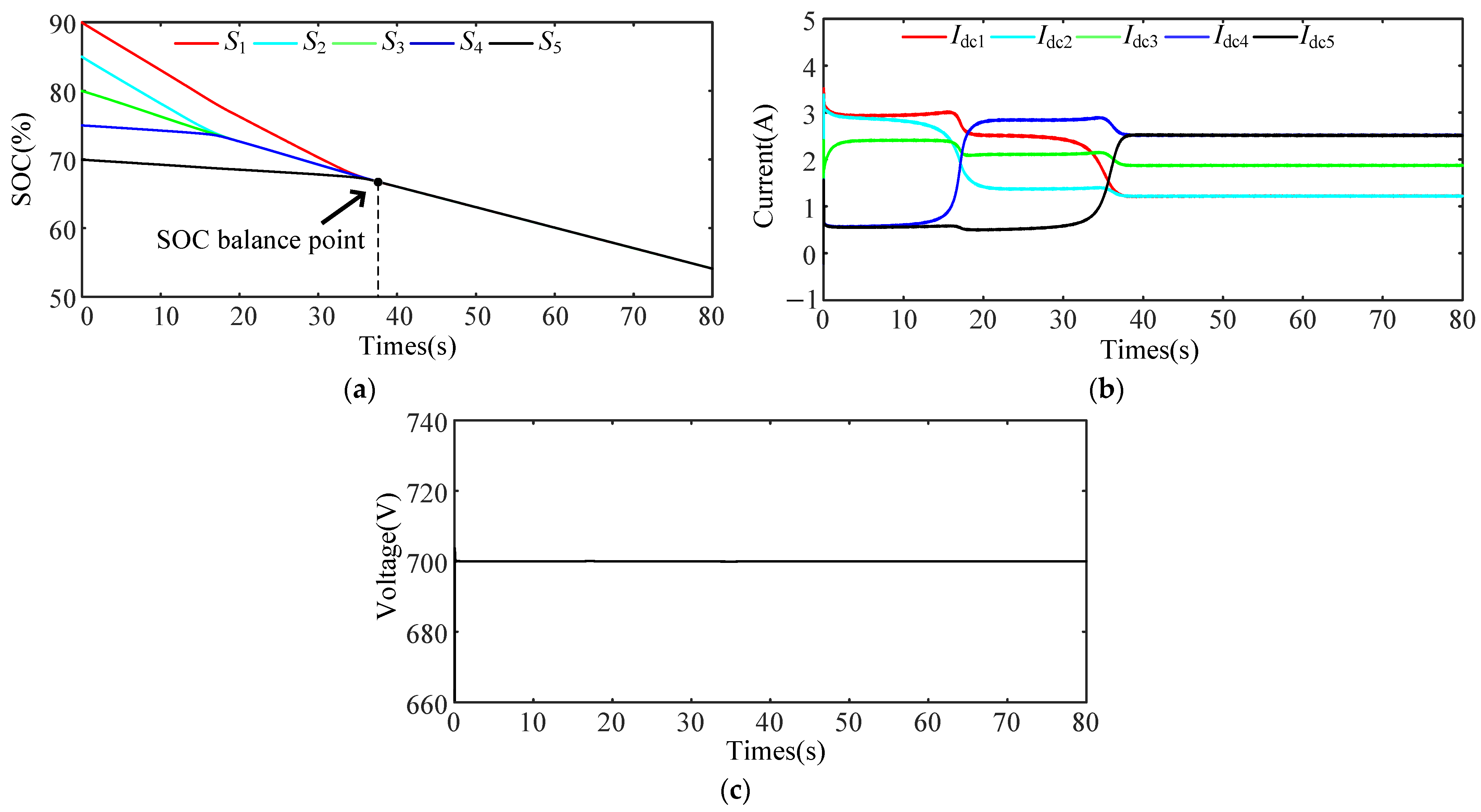
To assess the scalability of the proposed control strategy, the number of energy storage units was increased from three to five groups, with the communication topology illustrated in Figure 16. Initially, the SOC values are 90%, 85%, 80%, 75%, and 70%, with corresponding capacities Cb of 0.2 Ah, 0.2 Ah, 0.3 Ah, 0.4 Ah, and 0.4 Ah, respectively. The line impedances for the additional DESUs are 0.9 Ω and 1.1 Ω, while all other simulation parameters remain consistent with those of the original DESUs. The load power Pd is 7 kW, and the PV output power Pf is 427 W. The simulation results are presented in Figure 17.
In Figure 17a,b, the system is observed in a discharged state. At 20 s, the SOC for DESU2, DESU3, and DESU4 reached a balance, with their output currents precisely distributed by their respective capacities at a ratio of 2:3:4. By 38 s, all DESUs were balanced and stabilized. The output current is precisely allocated according to the 2:2:3:4:4 ratio of the storage unit capacity. Figure 17c shows that the bus voltage remains consistently stable at its rated value, ensuring a steady and efficient power supply. This case study vividly illustrates the proposed control strategy’s scalability and capability to uphold overall system stability and efficiency.

6. Conclusions

Under the circumstance of line impedance mismatch, to be satisfied with the requirements of fast SOC balancing and accurate allocation of load currents for multiple DESUs in DC microgrid systems, this paper proposes an improved SOC droop control strategy with the following main contributions:
(1)
By designing a new SOC balancing function, the SOC is closely associated with combining exponential function and power function, and two convergence factors and an adaptive acceleration factor are introduced. It effectively improves the problem of slow SOC balancing in the late stage of system operation, significantly accelerates SOC balancing, and improves the energy utilization efficiency of the DESUs.
(2)
To design a global optimization controller that combines bus voltage compensation and output current correction to achieve bus voltage stabilization and accurate load current distribution with only a simple integrator, it effectively reduces the communication burden of the system, reduces the control links, and improves the stability and reliability of the system operation.
(3)
The control strategy uses an improved consistency algorithm to obtain the global average state information and optimizes the communication topology combination of DESUs by establishing a sparse communication network, which dramatically reduces the system’s communication pressure and makes the method more adaptable to various complex working conditions.
This paper thoroughly analyzes the proposed control strategy’s fundamental principles and implementation process while validating the system’s stability under this approach. Simulation results validate the efficacy of the proposed control strategy in this study. Compared to traditional methods, the proposed strategy accelerates SOC balancing, yielding superior balancing effects in scenarios involving line impedance mismatch. This approach effectively safeguards DESU operations and extends the service life of ESS. Moreover, it reduces the system’s communication pressure to a greater extent and reduces the control link. However, due to each DESU’s communication interaction, communication delays may arise in DC microgrid operations. When these delays become substantial, they can cause voltage fluctuations at the bus or even lead to system instability. Consequently, the focus of subsequent research will be the study of coordinated control strategies for DC microgrids that consider communication delay.

Author Contributions

Conceptualization, Q.L. and J.W.; methodology, Q.L.; software, Q.L.; validation, Q.L., S.L. and X.H.; formal analysis, Q.L.; investigation, Q.L.; resources, J.W.; data curation, Q.L.; writing—original draft preparation, Q.L.; writing—review and editing, X.H. and J.W.; visualization, Q.L.; supervision, J.W.; project administration, Q.L.; funding acquisition, J.W. and S.L. All authors have read and agreed to the published version of the manuscript.

Funding

This study was supported by the National Natural Science Foundation of China (61963038), the Scientific Research Fund Project of the Yunnan Provincial Department of Education (2024Y432) and the Major Special Project of the Yunnan Provincial Department of Education Research Fund (ZD2013013).

Data Availability Statement

Data are contained within the article.

Conflicts of Interest

The authors declare no conflict of interest.

References

  1. Huang, B.; Zheng, S.; Wang, R.; Wang, H.; Xiao, J.; Wang, P. Distributed optimal control of DC microgrid considering balancing of charge state. IEEE Trans. Energy Convers. 2022, 37, 2162–2174. [Google Scholar]
  2. Peng, L.; Luo, L.; Yang, J.; Li, W. A Wind Power Fluctuation Smoothing Control Strategy for Energy Storage Systems Considering the State of Charge. Energies 2024, 17, 3132. [Google Scholar] [CrossRef]
  3. Xu, Z.; Chen, F.; Chen, K.; Lu, Q. Research on Adaptive Droop Control Strategy for a Solar-Storage DC Microgrid. Energies 2024, 17, 1454. [Google Scholar] [CrossRef]
  4. Li, B.; Yu, C.; Lu, X.; Wang, F. A novel adaptive droop control strategy for SoC balancing in PV-based DC microgrids. ISA Trans. 2023, 141, 351–364. [Google Scholar] [CrossRef] [PubMed]
  5. Chen, J.; Hu, H.; Wang, M.; Ge, Y.; Wang, K.; Huang, Y.; Yang, K.; He, Z.; Xu, Z.; Li, Y. Power flow control-based regenerative braking energy utilization in AC electrified railways: Review and future trends. IEEE Trans. Intell. Transp. Syst. 2024, 25, 6345–6365. [Google Scholar] [CrossRef]
  6. Huang, Z.; Li, Y.; Cheng, X.; Ke, M. A voltage-shifting-based state-of-charge balancing control for distributed energy storage systems in islanded DC microgrids. J. Energy Storage 2023, 69, 107861. [Google Scholar] [CrossRef]
  7. Lv, J.; Wang, X.; Wang, G.; Song, Y. Research on control strategy of isolated DC microgrid based on SOC of energy storage system. Electronics 2021, 10, 834. [Google Scholar] [CrossRef]
  8. Tian, G.; Zheng, Y.; Liu, G.; Zhang, J. SOC Balancing and Coordinated Control Based on Adaptive Droop Coefficient Algorithm for Energy Storage Units in DC Microgrid. Energies 2022, 15, 2943. [Google Scholar] [CrossRef]
  9. Yang, Z.; Wang, C.; Han, J.; Yang, F.; Shen, Y.; Min, H.; Hu, W.; Song, H. Analysis of voltage control strategies for DC microgrid with multiple types of energy storage systems. Electronics 2023, 12, 1661. [Google Scholar] [CrossRef]
  10. Kumar, R.; Pathak, M.K. Distributed droop control of dc microgrid for improved voltage regulation and current sharing. IET Renew. Power Gener. 2020, 14, 2499–2506. [Google Scholar] [CrossRef]
  11. Gorijeevaram Reddy, P.K.; Dasarathan, S.; Krishnasamy, V. Investigation of adaptive droop control applied to low-voltage DC microgrid. Energies 2021, 14, 5356. [Google Scholar] [CrossRef]
  12. Oliveira, T.R.; Silva, W.W.A.G.; Donoso-Garcia, P.F. Distributed secondary level control for energy storage management in DC microgrids. IEEE Trans. Smart Grid 2016, 8, 2597–2607. [Google Scholar] [CrossRef]
  13. Zhang, C.; Li, P.; Guo, Y. Bidirectional DC/DC and SOC drooping control for DC microgrid application. Electronics 2020, 9, 225. [Google Scholar] [CrossRef]
  14. Lu, X.; Sun, K.; Guerrero, J.M.; Vasquez, J.C.; Huang, L. State-of-charge balancing using adaptive droop control for distributed energy storage systems in DC microgrid applications. IEEE Trans. Ind. Electron. 2013, 61, 2804–2815. [Google Scholar] [CrossRef]
  15. Lu, X.; Sun, K.; Guerrero, J.M.; Vasquez, J.C.; Huang, L. Double-quadrant state-of-charge-based droop control method for distributed energy storage systems in autonomous DC microgrids. IEEE Trans. Smart Grid 2014, 6, 147–157. [Google Scholar] [CrossRef]
  16. Belal, E.K.; Yehia, D.M.; Azmy, A.M. Adaptive droop control for balancing SOC of distributed batteries in DC microgrids. IET Gener. Transm. Distrib. 2019, 13, 4667–4676. [Google Scholar] [CrossRef]
  17. Diaz, N.L.; Dragičević, T.; Vasquez, J.C.; Guerrero, J.M. Intelligent distributed generation and storage units for DC microgrids—A new concept on cooperative control without communications beyond droop control. IEEE Trans. Smart Grid 2014, 5, 2476–2485. [Google Scholar] [CrossRef]
  18. Zhang, L.; Li, T. SoC dynamic balancing strategy based on adaptive droop control with variable regulating factor. In Proceedings of the 2021 3rd Asia Energy and Electrical Engineering Symposium (AEEES), Chengdu, China, 26–29 March 2021; pp. 638–643. [Google Scholar]
  19. Mi, Y.; Guo, J.; Fu, Y.; Wang, C.; Wang, P. Accurate power allocation of multienergy storage island DC microgrid based on virtual power rating. IEEE Trans. Power Electron. 2022, 38, 261–270. [Google Scholar] [CrossRef]
  20. Silva, W.W.A.; Oliveira, T.R.; Donoso-Garcia, P.F. An improved voltage-shifting strategy to attain concomitant accurate power sharing and voltage restoration in droop-controlled DC microgrids. IEEE Trans. Power Electron. 2020, 36, 2396–2406. [Google Scholar] [CrossRef]
  21. Zhang, Q.; Zeng, Y.; Liu, Y.; Zhuang, X.; Zhang, H.; Hu, W.; Guo, H. An improved distributed cooperative control strategy for multiple energy storages parallel in islanded DC microgrid. IEEE J. Emerg. Sel. Top. Power Electron. 2021, 10, 455–468. [Google Scholar] [CrossRef]
  22. Hoang, K.D.; Lee, H.-H. Accurate power sharing with balancingd battery state of charge in distributed DC microgrid. IEEE Trans. Ind. Electron. 2018, 66, 1883–1893. [Google Scholar] [CrossRef]
  23. Andrade, P.; Alcaso, A.N.; Bento, F.; Marques Cardoso, A.J. Buck-Boost DC-DC Converters for Fuel Cell Applications in DC Microgrids—State-of-the-Art. Electronics 2022, 11, 3941. [Google Scholar] [CrossRef]
  24. Pang, C.; Wu, H.; Jia, B. A multi-mode coordinated operation control strategy for optical storage DC microgrid. Energy Rep. 2023, 9, 230–235. [Google Scholar] [CrossRef]
  25. Roy, T.K.; Oo, A.M.T.; Ghosh, S.K. Designing a High-Order Sliding Mode Controller for Photovoltaic-and Battery Energy Storage System-Based DC Microgrids with ANN-MPPT. Energies 2024, 17, 532. [Google Scholar] [CrossRef]
  26. Chen, X.; Tian, R.; Wang, Y.; Xu, S.; Jiang, W.; Hashimoto, S. A Novel Voltage-Current Dual-Drop Control Method for Shipboard DC Micro-Grid with Energy Storage Systems. IEEE Access 2024, 12, 62912–62925. [Google Scholar] [CrossRef]
  27. Tu, H.; Yu, H.; Lukic, S. Dynamic Nonlinear Droop Control (DNDC): A Novel Primary Control Method for DC Microgrids. IEEE Trans. Power Electron. 2024, 39, 10934–10949. [Google Scholar] [CrossRef]
  28. Yang, M.; Xin, C.; Liang, J. Accurate current sharing of distributed energy storage units in DC microgrid based on virtual rated current. Power System Technol. 2020, 44, 823–835. [Google Scholar]
Figure 1. DC microgrid structure diagram.
Energies 17 03885 g001
Figure 2. Equivalent circuit diagram of DESU in parallel.
Energies 17 03885 g002
Figure 3. Overall control block diagram.
Energies 17 03885 g003
Figure 4. DESUs’ communication topology network.
Energies 17 03885 g004
Figure 5. The effect of different values of m, p and n on Rd. (a) m = 5, n = 2; (b) m = 5, n = 4; (c) p = 5, n = 2; (d) p = 5, n = 4.
Energies 17 03885 g005aEnergies 17 03885 g005b
Figure 6. The effect of differences in α and d on Rd. (a) d = 0.1, α different; (b) α = 3, d different.
Energies 17 03885 g006
Figure 7. Droop control based on virtual current rating.
Energies 17 03885 g007
Figure 8. The control schematic of DESUi.
Energies 17 03885 g008
Figure 9. Trajectory diagram of the roots of the characteristic equations of the system. (a) r1 = 0.8 Ω, r2 = 1 Ω, Rload = 80 Ω, ωc = 60 rad/s and Rd1 increased from 1 to 50 Ω; (b) r1 = 0.8 Ω, r2 = 1 Ω, Rload = 100 Ω, Rd1 = 1 Ω and ωc increased from 10 to 60 rad/s; (c) r1 = 0.8 Ω, r2 = 1 Ω, Rd1 = 1 Ω, ωc = 5 rad/s and Rload increased from 10 to 1000 Ω; (d) r1 = 0.8 Ω, Rd1 = 1 Ω, Rload =80 Ω, ωc = 10 rad/s and r2 increased from 1 to 5 Ω.
Energies 17 03885 g009
Figure 10. Simulation results with the strategy mentioned in ref. [13] for Case 1. (a) SOC; (b) output current; (c) bus voltage.
Energies 17 03885 g010
Figure 11. Simulation results with the strategy mentioned in this paper for Case 1. (a) SOC; (b) output current; (c) bus voltage.
Energies 17 03885 g011
Figure 12. Simulation results with the strategy mentioned in ref. [13] for Case 2. (a) SOC; (b) output current; (c) bus voltage.
Energies 17 03885 g012
Figure 13. Simulation results with the strategy mentioned in this paper for Case 2. (a) SOC; (b) output current; (c) bus voltage.
Energies 17 03885 g013
Figure 14. Simulation results for Case 3. (a) Output power; (b) SOC; (c) output current; (d) bus voltage.
Energies 17 03885 g014
Figure 15. Simulation results for Case 4. (a) Output power; (b) SOC; (c) output current; (d) bus voltage.
Energies 17 03885 g015
Figure 16. Communication topology for five groups of energy storage.
Energies 17 03885 g016
Figure 17. Simulation results for Case 5. (a) SOC; (b) output current; (c) bus voltage.
Energies 17 03885 g017
Table 1. Comparison of different strategies for energy storage in DC microgrid.
Comparison of StrategiesSOC Balancing
Speed
Capacity
Difference
Overcoming Line Impedance
Mismatch
Bus Voltage
Restoration
[12]Slow×××
[13]Slow×××
[14]Slow×××
[15]Slow×××
[16]Slow××
[17]Slow×××
[18]Slow××
[19]Fast
[20]
[21]Fast
[22]Fast×
This paperFast
Table 2. Simulation parameters.
ParameterSymbolValue
Input-Side Capacitance of DC/DC ConverterC10.2 mF
Output-Side Capacitance of DC/DC ConverterC20.5 mF
Filter InductanceL0.9 mF
Line Impedancer10.8 Ω
r21.0 Ω
r31.2 Ω
Rated Bus VoltageUref700 V
Rated Battery VoltageU1400 V
U2400 V
U3400 V
Maximum Bus Voltage DeviationΔUmax35 V
Maximum Output CurrentIdcmax100 A
Initial Virtual ImpedanceRd00.35
Maximum Power of PVPfmax20 kW
Maximum Power of DESUPdmax20 kW
SOC Balancing Controller Factorm5
p6
n2
α4
d0.01
μ0.1
Global Optimization Controller FactorKui15
b111
b21
Switching Frequencyfs15 kHz
Cut-Off Frequencyωc60 rad/s
PI Controller Current LoopKPI + KII/s0.5 + 30/s
PI Controller Voltage LoopKPV + KIV/s1.5 + 60/s
Disclaimer/Publisher’s Note: The statements, opinions and data contained in all publications are solely those of the individual author(s) and contributor(s) and not of MDPI and/or the editor(s). MDPI and/or the editor(s) disclaim responsibility for any injury to people or property resulting from any ideas, methods, instructions or products referred to in the content.