Abstract
The hybrid active power filter (HAPF) can effectively suppress the 75–125 Hz low-frequency harmonic current generated by the EAST poloidal field power supply. However, the low-frequency harmonic current suppression performance of HAPF is greatly affected by its control parameters when the circuit parameters are determined. In this paper, the state–space equation of the HAPF system is established, and the relationship between the eigenvalues of the state–space matrix and the HAPF control parameters is analyzed using the Lyapunov method. Based on the variation law of the eigenvalues, by optimizing the control parameters of the HAPF system, the low-frequency harmonic current suppression performance of HAPF is improved by 41.9%.
1. Introduction
The Experimental Advanced Superconducting Tokamak (EAST) stands as the pioneering fully superconducting tokamak nuclear fusion experimental device that was conceived and built in China [1,2,3,4]. The power supply is an important component of EAST, and its poloidal field power is supplied to 14 symmetrical superconducting magnet coils through 12 sets of thyristor converters [5,6,7]. Due to the particularity of the EAST power supply load and the asymmetry of the converter’s starting angle, characteristic harmonic current and low-frequency harmonic current (75–125 Hz) are inevitably generated during poloidal field power supply operation, which is harmful to the power grid and other equipment in the EAST device [8,9,10].
In order to meet the stable operation requirements of the power supply under high-power and high-constraint modes of the EAST device and to prevent the impact of reactive power and harmonic currents on the system, the EAST device completed the renovation of the reactive power compensation and filtering system in 2011, increasing the original 13.82 Mvar reactive power and filtering branch fundamental compensation capacity to 38.86 Mvar [11,12,13]. Although the passive filter branch is added, the characteristic harmonic current generated by the poloidal field power supply in different operating modes is mainly considered, and the suppression measures of the non-characteristic harmonic current, especially the low-frequency harmonic current, are not considered.
In industry, an AC electric arc furnace (EAF) is a typical representative of generating low-order harmonics and inter-harmonics. The C-type high-pass filter is usually used to control the second-order and peripheral inter-harmonic components within a certain range [14,15]. However, due to the large amount of low-order harmonics occurring in the EAF, it is difficult to obtain good results from the conventional passive filter, and there is a need to configure a larger installation capacity [16,17,18,19]. For example, Baosteel has installed second, third, fourth, and fifth filtering compensation branches up to 180 Mvar on the 33 kV busbar and combined this with a thyristor control reactor to inhibit impact reactive power and harmonic current, but there is no significant effect on inter-harmonic resonance [20,21,22].
In the mining industry, the C-type passive filter is used in series with an active power filter to attenuate the low-frequency harmonics, subharmonics, and inter-harmonics generated during the operation of the cyclo-converters. The principle is that an active power filter generates an output voltage that is equal in magnitude and opposite in phase to the terminal voltage of the C-type filter, forcing the voltage drop at the connection between the C-type filter and the power grid to be equal to zero at this specific frequency. This is equivalent to creating a short-circuiting effect on low-frequency harmonics, subharmonics, or inter-harmonic currents of a specific frequency [23]. However, the main low-frequency harmonic currents generated during the operation of the EAST poloidal field power supply are in the frequency range of 75–125 Hz, and the amplitude and phase of the low-frequency harmonic currents are constantly changing (affected by the plasma configuration control of the EAST device). The hybrid method of using a C-type passive filter in series with an active power filter makes it difficult to effectively suppress low-frequency harmonic currents. Moreover, in this topology, the AC side of the active filter must withstand the fundamental voltage to maintain the stability of the DC side voltage, making it difficult to apply in high-capacity, low-frequency harmonic control scenarios such as the EAST poloidal field power supply system.
With the development of full control devices and the advancement of PWM control technology, active filters and low-voltage hybrid devices began to be widely used in loads such as computer information systems, frequency conversion equipment, and precision machining equipment [24,25]. Additionally, China Construction Bank’s Wuhan Disaster Recovery Center, Shanxi Xingneng Power Generation, and Yunnan Blue Crystal LED have installed active or hybrid equipment with a capacity of more than 5 MVA on the busbar, which can effectively suppress more than third harmonic current components.
Although the active filter device has advantages that are incomparable to the passive filter, it is limited by the capacity and cost of the switching device and cannot be mounted separately in large-capacity, high-voltage power grids. Therefore, by reducing the fundamental voltage on the AC side of the active inverter and lowering its overall capacity, hybrid devices have become the development direction of high-voltage active filtering technology in the future [26,27,28]. Some foreign and local scholars have made many beneficial explorations in this regard, but generally, most hybrid devices are still in the experimental and trial production stage, and only a few prototypes in industry have been put into operation. The hybrid active filter device with harmonic and resonance suppression will have broad prospects, and the hybrid compensation technology will be widely used [29,30].
The characteristic harmonic current can be filtered by setting the passive filter [31]. The low-frequency harmonic current is difficult to suppress due to its proximity to the fundamental frequency (50 Hz) [32], so it is difficult to filter with a passive filter. In this paper, the hybrid method with an active power filter (APF) and passive filter branch is applied to the control of low-frequency harmonic currents. However, the low-frequency harmonic current suppression performance of a hybrid active power filter (HAPF) is greatly affected by its control parameters, so it is necessary to further study the relationship between the control parameters of HAPF and the low-frequency harmonic current suppression ability.
The main contributions of this paper include the following three aspects. (1) A scheme of hybrid active power filters is proposed in this paper to suppress the low-frequency harmonic current in a 10 kV busbar. This scheme reduces the capacity of APF while using low-voltage APF for low-frequency harmonic suppression in high-voltage systems. (2) The global state–space equation of the HAPF system is established. The state–space equation includes the overall mathematical model of the HAPF system and the connection model with the power grid, which can fully reflect the dynamic characteristics of the HAPF system and provide theoretical support for the study of the influence of HAPF control parameters on low-frequency harmonic suppression performance. (3) The corresponding relationship between the HAPF control parameters and the eigenvalues of the system is analyzed, and the HAPF control parameters are optimized based on the variation law of the state–space matrix eigenvalues to improve the low-frequency harmonic suppression ability of HAPF.
2. Hybrid Active Power Filter
The hybrid active power filter evolved from the earliest parallel active power filter based on the principle of duality, and its main circuit topology and working principle have changed greatly compared with traditional active power filter devices. The resonant injection hybrid active power filter can effectively reduce the capacity of the APF and has a flexible control strategy and detection method. In addition, with excellent system stability, it can effectively suppress low-frequency harmonic current in the EAST poloidal field power supply system.
The topology of the resonant injection hybrid active power filter is shown in Figure 1. The low-frequency harmonic current generated by APF flows through the injection branch composed of inductor L0 capacitors C2, C1 to generate parallel resonance injected into the 10 kV busbar, so it is called the resonant injection hybrid active power filter. In this way, the low-voltage APF equipment can be applied to the harmonic current control of 10 kV or even higher voltage.
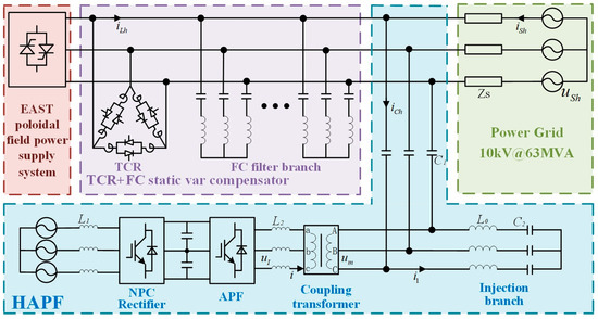
Figure 1.
Topology of the resonant injection HAPF.
Compared with the traditional APF, the APF of the HAPF system adopts a unique approach: it is connected in parallel with the fundamental wave series resonant circuit through a coupling transformer. In the injection branch of HAPF, the inductor L0 and the capacitor C2 form a series resonant circuit for the fundamental frequency. Because of this resonant characteristic, the combination of inductor L0 and capacitor C2 presents almost zero impedance at the fundamental frequency, so the APF does not take on fundamental voltage.
When this L0C2 resonant circuit is combined with a coupling transformer, the APF no longer needs to bear the fundamental voltage but only the harmonic voltage of the injection branch. This design method significantly reduces the capacity required for APF. At the same time, the 690 V low-voltage APF is applied to the low-frequency harmonic current suppression of the 10 kV high-voltage system, which is one of the innovations of this research work.
3. HAPF Mathematical Model
3.1. APF Mathematical Model
In the hybrid active power filter system, the active power filter is structured in three levels, as shown in Figure 2. Compared to the two-level APF, this topology improves the output waveform quality and reduces harmonic content during operation.
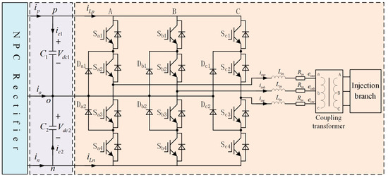
Figure 2.
The circuit topology of APF in HAPF.
According to the basic theorem of the circuit and the parameters in Figure 2, the AC side voltage equation of the three-level APF is obtained:
where , , . , , and represent the difference between the three-phase port voltage and the DC side voltage during APF operation. is the common mode voltage between the lower bridge node and the neutral point on the low-voltage side of the coupling transformer. , , and are the phase voltages on the low-voltage side of the coupling transformer. , , and are the three-phase output currents of APF.
The three-level APF mathematical model is obtained from the generalized park transformation of Equation (1).
where is the synchronous rotation angular frequency, represents the number of harmonics.
It can be seen that the three-level APF mathematical model is transformed from a three-input third-order linear system to a two-input second-order linear system after coordinate transformation.
3.2. HAPF System and Power Grid Connection Model
The NPC converter of the HAPF system is connected to the power grid through the rectifier transformer, and the three-level APF is connected to the injection branch through a coupling transformer, as shown in Figure 1. Therefore, to establish the HAPF’s mathematical model, it is essential to not only mathematically model the APF section but also establish a connection mathematical model between the HAPF system and the power grid.
Figure 3 shows the equivalent circuit connecting HAPF to the power grid. The voltage and current are in the form of vectors. is the NPC converter’s access network point; assuming that the power grid system capacity at point is infinite, then the voltage vector is . At point , the 10 kV busbar is connected to the EAST poloidal field power supply, and the three-level APF outputs harmonic voltage. According to the superposition theorem, point is equivalent to the ground point; that is, the voltage vector at point is zero.

Figure 3.
The equivalent circuit connecting HAPF to the power grid.
If the reactance of the rectifier transformer is equivalent to the high-voltage side, and the current reference direction is consistent with the direction marked in Figure 3, the relationship between the transformer current and voltage is as follows:
Further, we can obtain:
where is the ratio of the rectifier transformer, is the impedance of the rectifier transformer.
The relationship between voltage at point and grid side voltage at point is (the line resistance is ignored):
Transform Equation (5) to the dq coordinate system as follows:
Combined, Equations (4) and (6) obtain:
Similarly, if the reactance of the coupling transformer is equivalent to the high-voltage side, and the current reference direction is consistent with the direction marked in Figure 3, the relationship between the current and voltage of the coupling transformer is:
The park transformation of Equation (8) is obtained:
where is the ratio of the coupling transformer, and is the impedance of the coupling transformer.
The relationship between voltage at point and grid side voltage at point is (the line resistance is ignored):
where and are the impedance fundamental resonant branch L0C2 and the impedance of capacitance C1 in the injection branch, respectively.
Transform Equation (10) into the dq coordinate system as follows:
By combining Formulas (9) and (11), we get:
3.3. DC-Side Mathematical Model of HAPF
The function of the HAPF DC mathematical model is to unify the NPC converter mathematical model with the three-level APF mathematical model.
During the steady-state operation of the HAPF system, the fluctuation of the neutral point on the DC side of the system is suppressed. Therefore, the average value of the neutral point current on the DC side is about zero, which is . Furthermore, the split capacitor on the DC side can be equivalent to capacitor , and , . The equivalent DC-side circuit model is shown in Figure 4.
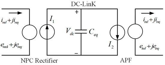
Figure 4.
DC-side equivalent circuit of the HAPF.
The NPC converter primarily utilizes DC-side voltage and AC-side current as control signals. It ensures a consistent output of DC-side bus voltage and operates with a high power factor on the NPC converter AC-side during the bidirectional energy flow. The three-level APF mainly detects low-frequency harmonic currents as input signals and controls the output harmonic voltage to suppress low-frequency harmonic currents in the busbar. The relationship between the NPC converter DC-side current and the injected APF current can be obtained from Figure 4.
Among them:
where and represent the lost power on the AC side of the NPC converter and the three-level APF.
During operation of the HAPF system, the switching losses, conduction losses, and line losses of the NPC converter and three-level APF are typically disregarded. Following the principle of power conservation, the energy stored in the DC capacitor equals the variance between the input power of the NPC converter and the output power of the APF. Therefore, the equation for the DC-side capacitance is:
3.4. Mathematical Model of HAPF Control System
The function of HAPF is to suppress the low-frequency harmonic current generated in the operation of the EAST poloidal field power supply. In the specific working process, the low-frequency harmonic current in the poloidal field 10 kV busbar and the injected branch is detected, and the corresponding low-frequency harmonic voltage is output by the three-level APF. It is also used for the APF outlet filter, fundamental resonance branch, and injection branch capacitor so as to suppress the low-frequency harmonic current in the 10 kV busbar. It is necessary to design and model the control system of HAPF based on its low-frequency harmonic current suppression performance.
The HAPF control strategy is shown in Figure 5. The low-frequency harmonic currents in the AC side of the EAST poloidal field power supply and the injection branch are obtained by detecting the low-frequency harmonic current, and the detected low-frequency harmonic current and are used as the reference values for the output low-frequency harmonic currents of the APF. The APF outputs harmonic current components and as feedback values, which are further compared with components and to obtain error components for adjustment. To mitigate the impact of APF AC side harmonic voltage fluctuations on the control strategy, a voltage feedforward is introduced in the control system, along with components and . The adjusted error component, combined with voltage feedforward components, undergoes mathematical operations with the state feedback component to derive the APF control command voltage. This voltage is then used to implement voltage space vector pulse width modulation (SVPWM) for APF control.
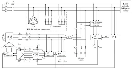
Figure 5.
The control strategy of the HAPF.
From Figure 5, the governing equation of APF in the HAPF system in the dq coordinate system is obtained:
where the state variables and are actual values in units of . and are the proportional coefficients of the current loop controller. and are the integral time constant of the current loop controller in units of . represents the number of harmonics.
3.5. Mathematical Model of the HAPF
The differential algebraic equations of each unit of the HAPF system are established above. It can be seen that there is mutual coupling between the various parts of the system, and the output of the HAPF is not only related to the structural parameters of the system but also closely related to the initial state and input of the system. Therefore, the HAPF system has strong non-linear characteristics. In order to study the stability performance of the HAPF system, this paper adopts the Lyapunov linearization method. Its basic idea is to linearize the differential–algebraic equation of the HAPF system near the equilibrium point of the system. When the HAPF system fluctuates in a small range, the HAPF and its linearized system have similar characteristics, so the stability performance of the HAPF non-linear system can be analyzed.
The differential algebraic equations of each element of the HAPF system are linearized, and the intermediate variables are eliminated to obtain the state–space mathematical model of the HAPF system, as shown in Equation (16).
The state variable in the equation is:
The state–space matrix is:
where , , , , , , , , , , , , , , , , , , , , , , .
, , , , , and , are NPC rectifier control parameters. For the mathematical model of the NPC rectifier, please refer to the author’s paper ref. [33].
The state–space equation of the HAPF system not only includes electrical parameters in the topology structure, but also control parameters in the control system. According to Equation (15), it can be seen that the state–space matrix of the state–space equation is a sparse matrix of 12 × 12. Based on the distribution of eigenvalues in this matrix, the dynamic characteristics of the HAPF system can be determined, which provides theoretical support for the study of the influence of HAPF control parameters on the low-frequency harmonic suppression performance. This is another innovation of this research work.
4. HAPF Stability Analysis
Based on the stability of the control system, the Lyapunov is used to analyze the stability performance and resist disturbance of the HAPF system, which includes the electrical parameters of the circuit and the control system parameters, and further optimize the control parameters according to the eigenvalue variation rule of the state–space matrix.
4.1. Eigenvalues and Stability Analysis of the HAPF
According to the state–space equation of the HAPF system obtained by mathematical modeling in Section 3, the stability of the HAPF system is analyzed by substituting the state–space matrix into the electrical and control parameters of the system. The HAPF system parameters are shown in Table 1.

Table 1.
HAPF system parameters.
Then, we substitute the parameters in Table 1 into the state–space matrix of Equation (16) and use MATLAB 2021b calculation software to obtain the eigenvalues, oscillation frequency, and damping ratio of the HAPF system.
It can be seen from Table 2 that all eigenvalues of the state–space matrix have negative real parts, so the HAPF system can reach a stable state again after suffering a small disturbance. In addition, the system has two attenuation modes (feature roots are real numbers) and five oscillation modes (feature roots are conjugate complex numbers), and the oscillation frequencies are far from the normal operating frequencies of the HAPF system. However, the damping of the five oscillation modes is relatively small. When the system is disturbed, it takes a long time to recover to a stable state, and the small disturbance may cause system fluctuations. By studying the variation patterns of control parameters and eigenvalues in the system, the control parameters can be further optimized to improve the damping ratio, dynamic performance, and anti-interference ability of the HAPF system.

Table 2.
Eigenvalues of state–space matrix .
4.2. Eigenvalue Analysis and Control Parameter Optimization
In order to facilitate the analysis of the eigenvalues of the state–space matrix , parameter is introduced, and when and change, the trend of the eigenvalues of the state–space matrix of the HAPF system is shown in Figure 6. Figure 6a,b show the variation trend of the HAPF system’s characteristic values when the voltage outer loop control parameters of the NPC converter change. It can be seen that the eigenvalues and are affected by and . is a pair of conjugate eigenvalues, and with the increase of , moves in the opposite direction on the real axis, and the real part of moves towards the region greater than zero, which easily leads to system instability. Therefore, the value of should not be too large.
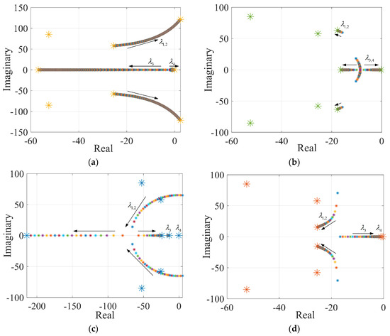
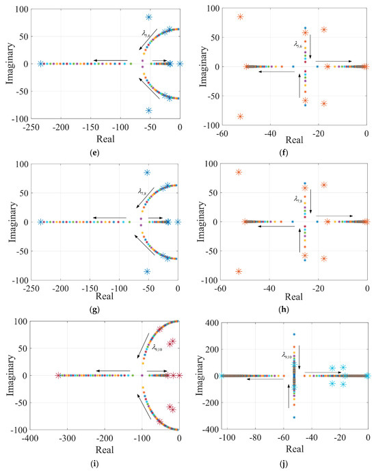
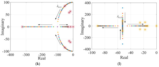
Figure 6.
The eigenvalue traces of HAPF system when controlling parameter changes. (a) , ; (b) , ; (c) , ; (d) , ; (e) , ; (f) , ; (g) , ; (h) , ; (i) , ; (j) , ; (k) , ; (l) , .
has little influence on the eigenvalue , and mainly affects the change of . With the increase in , changes from a pair of conjugate eigenvalues to two eigenvalues on the real axis, one of which moves towards the left stable region and the other towards the right unstable region. Therefore, it is necessary to select an appropriate value to ensure the stability of the voltage outer loop.
Figure 6c–h shows the characteristic value trends of the HAPF system when the inner loop control parameters of the NPC converter current change. It can be seen that and also have an impact on the eigenvalues and , and mainly causes changes in the eigenvalue but has little impact on . When is small, is a pair of conjugate eigenvalues, and with the increase in , the real part of gradually increases, and the imaginary part gradually decreases. Finally, the two oscillation modes evolve into attenuation modes, and one eigenvalue moves towards the left stable region, as another eigenvalue moves towards the unstable region.
Control parameter has influence on both eigenvalues and . When increases, the real part of increases, and the imaginary part decreases, while the eigenvalue moves toward the unstable region on the real axis. The changing trend of eigenvalues and should be comprehensively considered when selecting control parameter to ensure the stability of the system. Since the operating frequency of the AC side of the NPC converter is 50 Hz, the mode oscillation frequency should be as far away from 50 Hz as possible. According to the above analysis, the imaginary part of the characteristic value should be as small as possible to make the mode oscillation frequency far away from the power frequency of 50 Hz.
To sum up, the principle of selecting control parameters , , , and is to make the eigenvalues and conjugate eigenvalues with large real parts and small imaginary parts to ensure the stable operation of the HAPF system while taking into account the dynamic characteristics of the system. In addition, and are the control parameters of the current inner loop, which should be prioritized in parameter selection.
, , , and are the control parameters of the current loop axis and axis of the NPC converter. and mainly affect the change of characteristic value , and parameters and affect the change of the characteristic value . The influence of and on the eigenvalues and is similar to that of on . When the values of and are small, both and are conjugate eigenvalues. With the increase in the values of and , the real part of and increases, and the imaginary part gradually decreases, and finally, the two conjugate eigenvalues evolve into two real axis eigenvalues, one of which moves to the left half plane, the other eigenvalue moves towards the right half plane.
The influence of control parameters and on and is basically the same. When the values of and are small, and are two pairs of conjugate eigenvalues. As the values of and increase, the real part of and remains unchanged, and the imaginary part decreases. When it changes to the attenuation mode, one eigenvalue gradually moves to the left plane, and the other eigenvalue gradually moves to the right plane. The principle governing the selection of parameters , , and , is also that the eigenvalues and , which are conjugate eigenvalues with large real parts and small imaginary parts.
Figure 6i–l shows the influences of three-level APF control parameters , , , and of the HAPF system on the eigenvalues and . The change trajectory of and is similar to that of the eigenvalues and , and the analysis process and the principle of parameter optimization are also basically consistent, so it is not repeated here.
Based on the above analysis, reasonable control parameters are selected according to the changing trend of eigenvalues to make the eigenvalues have larger real parts and smaller imaginary parts so as to ensure the HAPF system has good stability performance and anti-interference ability. The new control parameters are shown in Table 3.

Table 3.
Control parameters of HAPF system after optimization.
Substituting the optimized control parameters from Table 3 into the state–space matrix , and combining c with the simulation calculation software, the HAPF system characteristic values are obtained, as shown in Table 4.

Table 4.
Eigenvalues of state–space matrix under optimized control parameters.
From Table 4, it can be seen that after optimizing the control parameters, the eigenvalues of the oscillation mode in the HAPF system exhibit larger real parts and smaller imaginary parts, which makes the oscillation frequency of the system far away from its operating frequency. Furthermore, the HAPF system demonstrates a higher damping ratio, thereby enhancing its anti-interference capability and stability.
5. Simulation Verification
By establishing the MATLAB/Simulink 2021b simulation model, the performance of EAST 10 kV HAPF is verified. In accordance with the EAST experimental process, the actual harmonic current value generated by the operation of the poloidal field power supply is measured by the PW3198 power quality analyzer. In the simulation model, the harmonic current measured during the operation of the poloidal field power supply is equivalent by setting the amplitude, frequency, and phase information of the current source.
In the simulation model of the HAPF system, the harmonic source equivalent to the poloidal field power source becomes operational at 0.05 s, followed by the HAPF system at 0.2 s. The current waveform of the 10 kV busbar throughout the process is illustrated in Figure 7a. It is evident that a slight current flows in the bus when the harmonic source is inactive, attributed to the TCR-type reactive power compensation device’s operation. Upon activation of the harmonic source, as observed in Figure 7b, the presence of third, fifth, seventh, eleventh, and thirteenth-order passive filter branches leads to a notable reduction in harmonic current in the 10 kV busbar. However, the low-frequency harmonic current content around 100 Hz remains elevated.
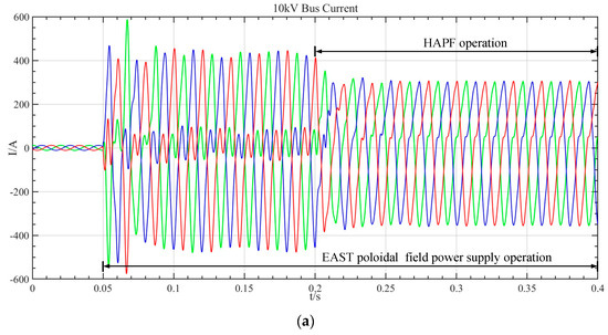
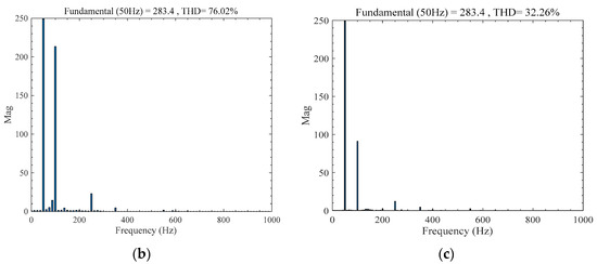
Figure 7.
Low-frequency harmonic suppression effect of HAPF system before optimizing control parameters. (a) Three-phase current waveform at the EAST 10 kV busbar. (b) FFT analysis of 10 kV busbar current when EAST poloidal field power supply is running. (c) FFT analysis of 10 kV busbar current after HAPF is put into operation.
The three-level APF in the HAPF system adopts the control strategy in Figure 5, and the control parameters are shown in Table 1. When the HAPF is put into operation at 0.2 s, the overall operation of the system is stable, the current amplitude at the 10 kV busbar decreases, and the sinusoidal degree increases. According to the Fourier analysis of the waveform, the low-frequency harmonic current in the busbar is reduced from 217.6 A to 92.3 A, meeting the requirements of the Chinese standard limit (Chinese standard limit 96 A), and the waveform distortion rate is reduced from THD = 76.02% to THD = 32.26%, as shown in Figure 7c.
The study further validates the low-frequency harmonic current suppression capabilities of the HAPF based on the optimized control parameters outlined in Table 3. It is also an equivalent harmonic source of the EAST poloidal field power supply that operates at 0.05 s and is put into the HAPF device at 0.2 s, as shown in Figure 8. Analysis of Figure 8a,c reveals that upon activation of the HAPF device with optimized control parameters, the low-frequency harmonic current in the 10 kV bus decreases to 53.4 A. This represents a 41.9% improvement in low-frequency harmonic suppression performance, resulting in a 10 kV busbar current that closely resembles a sine wave and reduced current distortion rate of THD = 19.65%. These findings demonstrate that optimizing the control parameters can effectively enhance the overall performance of the HAPF system and improve its harmonic suppression capabilities when the system’s topology structure and hardware circuit parameters remain constant.
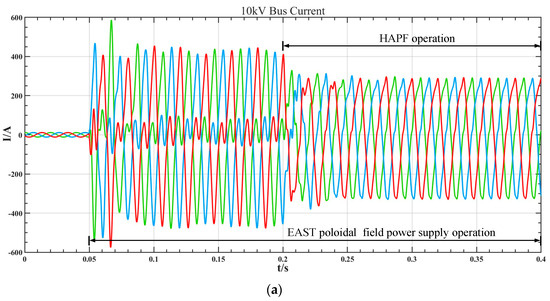
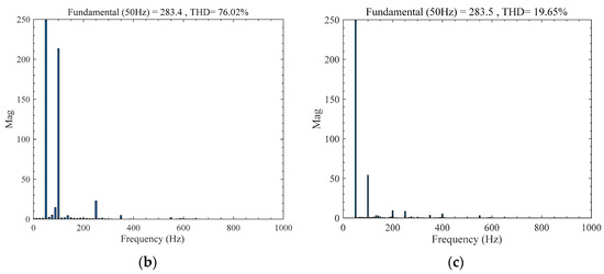
Figure 8.
Low-frequency harmonic suppression effect of HAPF system after optimizing control parameters. (a) Three-phase current waveform at the EAST 10 kV busbar. (b) FFT analysis of 10 kV busbar current when EAST poloidal field power supply is running. (c) FFT analysis of 10 kV busbar current when HAPF is put into operation after optimizing control parameters.
6. Conclusions
The low-frequency harmonic current generated by the operation of the EAST poloidal field power supply system seriously threatens the safety of the power grid and other equipment. In this paper, a hybrid active power filter scheme combining an active filter and a passive filter is proposed, the state–space equation of the HAPF system is established, and the influence of the HAPF system control parameters on the eigenvalues of the state–space matrix is studied. The HAPF system’s uncontrolled parameters are optimized by the trend of characteristic values to improve its ability to suppress low-frequency harmonic current. The optimized HAPF system effectively decreased the low-frequency harmonic current in the 10 kV busbar from 92.3 A to 53.4 A, resulting in a reduction in the THD from 32.26% to 19.65%. The research results can provide reference and guidance for the low-frequency harmonic control of power supply systems in other tokamak fusion devices.
Although it is proposed in this paper that HAPF can suppress the low-frequency harmonic current generated during the operation of the EAST poloidal field power supply, the application of HAPF to the control of uncharacteristic harmonics generated by converters in power systems needs further verification. Therefore, in future work, we will improve the HAPF topology and its control strategy so that it can suppress the uncharacteristic harmonic current in the power system.
Author Contributions
Conceptualization, J.T. and Y.W.; methodology, Y.W.; software, X.S.; formal analysis, X.S.; investigation, T.D.; data curation, Q.Z.; writing—original draft, X.S.; writing—review and editing, T.D., Q.Z. and F.P.; project administration, J.T. All authors have read and agreed to the published version of the manuscript.
Funding
This work was supported by the National Natural Science Foundation of China under Grant 52177165 and Anhui Province Higher Education Science Research Project 2022AH050105, 2023AH050074, 2023AH050075.
Data Availability Statement
The data that support the findings of this study are available from the corresponding author upon reasonable request.
Conflicts of Interest
The authors declare no conflicts of interest.
References
- Li, J.; Guo, H.Y.; Wan, B.N.; Liang, Y.F.; Xu, G.S. Recent progress on EAST. Fusion Sci. Technol. 2017, 64, 417–423. [Google Scholar] [CrossRef]
- Hu, L.; Zhou, Z.; Zhuang, M.; Zhang, Q.; Zhu, Z. Alarm and interlock system in cryogenic system of EAST. IEEE Trans. Appl. Supercond. 2020, 30, 4203105. [Google Scholar] [CrossRef]
- Wan, B.N.; Xu, G.S. Advances in experimental research towards high confinement and steady state operation on the experimental advanced superconducting Tokamak. Sci. Sin.-Phys. Mech. Astron. 2019, 49, 47–59. [Google Scholar] [CrossRef]
- Wan, B.; Gong, X.; Liang, Y.; Xiang, N.; Xu, G.S.; Sun, Y.; Wang, L.; Qian, J.; Liu, H.; Zhang, B.; et al. Advances in the long-pulse steady-state high beta H-mode scenario with active controls of divertor heat and particle fluxes in EAST. Nucl. Fusion 2022, 62, 042010. [Google Scholar] [CrossRef]
- Liu, Y.; Fu, P.; Zhang, X.; Huang, L.; He, S.; Chen, X. Design the phase output bar for improving static and dynamic current distribution among parallel IGBTs in high power rectifier bridge arm of the super-conducting Tokamak (EAST). IEEE Trans. Plasma Sci. 2024; Early Access. [Google Scholar] [CrossRef]
- Ali, M.; Labouré, E.; Costa, F. Integrated active filter for differential-mode noise suppression. IEEE Trans. Power Electron. 2014, 29, 1503–1507. [Google Scholar] [CrossRef]
- Huang, R.L.; Zhu, Y.F.; Fu, P.; Huang, L.S.; Wang, Z.M.; Xu, L.W.; Gao, G. Research on short circuit operation control strategy of a superconducting magnet power supply for CRAFT. J. Fusion Energy 2021, 40, 21. [Google Scholar] [CrossRef]
- He, S.; Huang, L.; Gao, G.; Wang, G.; Wang, Z.; Chen, X. Design of real-time control in poloidal field power supply based on finite-state machine. IEEE Trans. Plasma Sci. 2019, 47, 1878–1883. [Google Scholar] [CrossRef]
- Ji, Y.; Yuan, H.W.; Xu, L.W.; Wu, Y.N.; Guo, Q.; Mao, H.F.; Li, J. Control and operation mode of ITER high-power DC testing platform. J. Fusion Energy 2015, 34, 1483–1488. [Google Scholar] [CrossRef]
- Qu, J.; Fu, P.; Wu, Y.N.; Lu, J.; Zhu, M.X.; Liang, Y.; Tian, Y.X. Power quality analysis for poloidal field power supply system in EAST. Fusion Sci. Technol. 2021, 77, 316–326. [Google Scholar] [CrossRef]
- Miao, P.C.; Li, G.; Weng, Z.Y. Analysis of the vertical field on EAST for long-pulse H-mode discharges. IEEE Trans. Plasma Sci. 2020, 48, 280–284. [Google Scholar] [CrossRef]
- Shen, X.S.; Tao, J.; Deng, T.B.; Wu, Y.N.; Wu, S.Y. Research on harmonic suppression characteristics and control methods for low-frequency resonance suppressor. Fusion Eng. Des. 2024, 204, 114462. [Google Scholar] [CrossRef]
- Lu, J.; Fu, P.; Li, J.; Mao, H.F.; Xu, L.W.; Wu, Y.N. A new hybrid filter based on differential current control method for low-order harmonic suppression in Tokamak power system. Int. J. Energy Res. 2018, 42, 82–90. [Google Scholar] [CrossRef]
- Ai, L.; Hu, H.; Li, Z.; Wang, Y.; Guo, X. A novel frequency tuning scheme for a C-type filter based on the best filtering frequency. IEEE Trans. Power Deliv. 2023, 38, 3021–3032. [Google Scholar] [CrossRef]
- Aleem, S.H.E.A.; Zobaa, A.F.; Aziz, M.M.A. Optimal C-type passive filter based on minimization of the voltage harmonic distortion for nonlinear loads. IEEE Trans. Ind. Electron. 2012, 59, 281–289. [Google Scholar] [CrossRef]
- Mishra, R.; Saha, T.K. Control of a stand-alone distributed generation system with unbalanced and nonlinear load. Int. Trans. Electr. Energy Syst. 2020, 30, e12286. [Google Scholar] [CrossRef]
- Moradian, M.; Soltani, J. An isolated three-phase induction generator system with dual stator winding sets under unbalanced load condition. IEEE Trans Energy Convers. 2016, 31, 531–539. [Google Scholar] [CrossRef]
- Kraimia, M.N.; Boudour, M. Harmonic interaction of a static var compensator with AC power system containing multiple non-linear loads. Eng. Rev. 2020, 40, 21–31. [Google Scholar] [CrossRef]
- Liu, Y.; Xu, W.; Zhu, J.; Blaabjerg, F. Sensorless Control of standalone brushless doubly fed induction generator feeding unbalanced loads in a ship shaft power generation system. IEEE Trans. Ind. Electron. 2018, 66, 739–749. [Google Scholar] [CrossRef]
- Wang, W. SVC Power Supply Method of High Power AC EAF and Power Quality Control; Shanghai Jiao Tong University: Shanghai, China, 2008. [Google Scholar]
- Gu, J.J.; Li, K.; Zheng, Y.Z. Research on model of DC furnace system of Baosteel. Metall. Power 2011, 4, 1–3, 42. [Google Scholar]
- Xue, L.N. Study on Operating Characteristic Model and Virtual Control of a 350 MW Thermal Power Unit; Southeast University: Nanjing, China, 2018. [Google Scholar]
- Aravena, P.; Moran, L.; Dixon, J.; Espinoza, J.; Godoy, O. A new hybrid filter topology for sub and inter-harmonic attenuation in cycloconverter-fed drives applications. In Proceedings of the IEEE Industry Applications Society Annual Meeting, Houston, TX, USA, 4–8 October 2009; pp. 1–7. [Google Scholar]
- Popescu, M.; Bitoleanu, A.; Constantin, V.S.; Linca, M.; Subtirelu, G.E. Adaptive control of DC voltage in three-phase three-wire shunt active power filters systems. Energies 2020, 13, 3147. [Google Scholar] [CrossRef]
- Lumbreras, D.; Gálvez, E.; Collado, A.; Zaragoza, J. Trends in power quality, harmonic mitigation and standards for light and heavy industries: A review. Energies 2020, 13, 5792. [Google Scholar] [CrossRef]
- Wu, Y.; Chen, R.; Li, C.; Zhang, L.; Dai, W. An adaptive sine-cosine moth-flame optimization algorithm for parameter identification of hybrid active power filters in power systems. IEEE Access 2020, 8, 156378–156393. [Google Scholar] [CrossRef]
- Akagi, H. New trends in active filters for power conditioning. IEEE Trans. Ind. Appl. 1996, 32, 1312–1322. [Google Scholar] [CrossRef]
- Tiwari, A.K.; Dubey, S.P. Ant colony optimization based hybrid active power filter for harmonic compensation. In Proceedings of the 2016 International Conference on Electrical, Electronics, and Optimization Techniques (ICEEOT), Chennai, India, 3–5 March 2016; pp. 777–782. [Google Scholar]
- Sou, W.K.; Choi, W.H.; Chao, C.W.; Lam, C.S.; Gong, C.; Wong, C.K.; Wong, M.C. A deadbeat current controller of LC-hybrid active power filter for power quality improvement. IEEE J. Emerg. Sel. Top. Power Electron. 2020, 8, 3891–3905. [Google Scholar] [CrossRef]
- Karbasforooshan, M.-S.; Monfared, M. Adaptive predictive deadbeat current control of single-phase multi-tuned shunt hybrid active power filters. IEEE Trans. Power Deliv. 2024, 39, 446–454. [Google Scholar] [CrossRef]
- Herman, L.; Knez, K.; Blažič, B. Design and performance evaluation of a hybrid active power filter controller. Energies 2024, 17, 2492. [Google Scholar] [CrossRef]
- Liu, Q.Y.; Li, Y.; Hu, S.J.; Luo, L.F. A transformer integrated filtering system for power quality improvement of industrial DC supply system. IEEE Trans. Ind. Electron. 2020, 67, 3329–3339. [Google Scholar] [CrossRef]
- Shen, X.S.; Gao, G.; Wu, Y.N.; Lu, J.; Tan, L.; Tian, Y.X.; Dai, M.Y.; Zou, T.; Liang, Y. Control parameters optimization of three-level neutral-point clamp rectifier for EAST low-frequency resonance suppressor. Fusion Eng. Des. 2021, 170, 112486. [Google Scholar] [CrossRef]
Disclaimer/Publisher’s Note: The statements, opinions and data contained in all publications are solely those of the individual author(s) and contributor(s) and not of MDPI and/or the editor(s). MDPI and/or the editor(s) disclaim responsibility for any injury to people or property resulting from any ideas, methods, instructions or products referred to in the content. |
© 2024 by the authors. Licensee MDPI, Basel, Switzerland. This article is an open access article distributed under the terms and conditions of the Creative Commons Attribution (CC BY) license (https://creativecommons.org/licenses/by/4.0/).