Abstract
Pulsating heat pipes (PHPs) are widely used in the heat dissipation of electronic components, waste heat recovery, solar energy utilization, etc., relying on the pulsating flow of the work material in the pipe and the heat transfer by phase change, and they have the advantages of high heat-transfer efficiency, simple structure, and low cost. In this paper, an experimental method is used to adjust the length of local pipes in the PHP structure, so that the PHP forms a high- and low-staggered asymmetric structure, and to study the effects of different liquid charging rates and heat-source temperatures on the vibration, startup, and operation of the PHP in the asymmetric structure. We found the following: it is difficult to start up and operate the workpiece at 10%, 68%, and 80% liquid charging rates; the effect of the oscillating impact is worse; the temperature difference between the evaporation section of the pulsating heat pipe and condensation section is larger; and the temperature difference between the evaporation section and condensation section is larger. The temperature difference between the evaporation section and condensation section of the pulsating heat pipe is large, the temperature difference is between 10~25 °C, and it is difficult to achieve a small temperature difference in heat transfer. When the liquid charging rate is 30% and 50%, the pulsating heat pipe oscillates better; the pulsation frequency is relatively high; and the temperature difference between the end of the cold and hot sections is small, the temperature difference is between 3 and 7 °C, and the performance of heat transfer is better. However, when the liquid charging rate is 30% and the heat source is 70 °C, the thermal resistance is increased to 0.016 K/W, and the equivalent thermal conductivity is reduced. When the performance of heat transfer is changed to 0.016 K/W and the equivalent thermal conductivity is reduced, the coefficient decreases, and the heat-transfer performance becomes weaker.
1. Introduction
PHPs (pulsating heat pipe, PHP) are a new type of heat pipe proposed by a Japanese scholar, H. Akachi, whose inner diameter channel is skinny so that under surface tension, the work material forms randomly distributed vapor plugs and liquid plugs in the channel. When PHPs work, the heat absorbed by the evaporating section and released by the condensing section leads to expansion, compression, and mutual transformation; this forms the driving force of the liquid plug oscillation movement, and the heat is continuously transferred from the evaporation section to the condensation section [1,2,3,4]. Based on inheriting the characteristics of traditional heat pipes, such as simplicity, reliability, and low price, the pulsating heat pipe further overcomes limiting conditions such as susceptibility to carryover and boiling and improves the heat transfer limit of the heat pipe as a whole, which has the advantages of fast thermal response, strong heat-transfer performance, and environmental adaptability. PHPs are used in the fields of nuclear energy, thermal management [5,6,7,8], solar thermal utilization [9,10,11], waste heat recovery [12,13,14,15], the cooling of electronic devices [16,17], new energy heat-transfer technology, high-temperature superconductivity [18], thermal storage [19,20,21], and aerospace cooling [22,23,24]. Furthermore, they have high potential for application in other areas of heat transfer.
Currently, due to the complexity of the operation mechanism, there are many influencing factors, such as structure, inclination angle, liquid filling rate, physical properties of the work material, etc. Ayel et al. [25] conducted an experimental study on a closed-loop flat-plate pulsating heat pipe with a liquid filling rate of 50% at different inclination angles and found that at an inclination angle of 45° to 90°, the pulsating heat pipe has good heat-transfer performance. Wu et al. [26] conducted a study on a liquid-metal high-temperature oscillating heat pipes with different filling rates and found that at a filling rate from 35% to 64, the pulsating heat pipe tends to show unidirectional circulation flow, and the heat-transfer performance is significantly enhanced. The study of different liquid filling rates was carried out, and it was found that the pulsating heat pipe was prone to unidirectional circulating flow, and the heat-transfer performance was significantly enhanced when the liquid filling rate was from 35% to 64%. Fan [27] et al., to understand the stability of the work material on the heat-transfer performance of the pulsating heat pipe, added a certain proportion of copper oxide nanoparticles to an ethanol solution, and it was found that when adding 1–2.5 wt% of the copper oxide nanoparticles, the whole system of the pulsating heat pipe has good and stable heat-transfer performance, and when more than 6 wt% was added, the heat-transfer performance tends to be unstable. There are many factors affecting the pulsating heat pipe, but it is difficult to make significant improvement in the heat-transfer performance of the pulsating heat pipe by changing the conventional factors. Strengthening the heat-transfer performance of PHPs by changing the structure is the focus of the current research, so the innovative change of the structure can make PHPs realize the diversified transformation of the flow pattern and the destruction of the boundary layer during the operation process and improve the latent and sensible heat capacity. This can effectively reduce the thermal resistance of the operation of PHPs and enhance the heat-transfer performance, which is favorable to the circulating oscillation of the working mass.
In the current literature, research on pulsating heat pipes with asymmetric structures mainly focuses on asymmetric pipe-diameter channels. Scholars have strengthened the heat-transfer performance of pulsating heat pipes by changing the pipe-diameter size of individual channels—for example, Jang et al. [28] used asymmetric channels with increased differential pressure and an unbalanced driving force. They found that this could improve the thermal performance of a flat-plate pulsating heat pipe in a compact electronic device. Est Dev Patel et al. [29] conducted heat-transfer performance experiments on asymmetric single-turn closed-loop pulsating heat pipes. They concluded that the asymmetric channel enhances unidirectional two-phase flow oscillations, which improves the thermal performance. Shukla et al. [30] designed an asymmetric two-ring pulsating heat pipe with different sizes of tubes by employing borosilicate glass tubes, which was compared with a conventional symmetric pulsating heat pipe of equal diameters, and it was found that this asymmetry can promote the startup and single-cycle flow of pulsating heat pipes—at a low heat load, characteristics were especially obvious. However, the shortcomings of this asymmetry—by changing the size of the pipe diameter—is that the pipe diameter of the pulsating heat pipe will affect the flow rate of the mass, but the mass flows from the larger-diameter channel to the smaller-diameter channel when the resistance increases rather than reducing the overall flow rate of the mass, thus affecting the overall heat-transfer performance.
Since the current research on asymmetric pulsating heat pipes in the literature is limited to the asymmetric pipe-diameter channel size, this paper realizes the asymmetric structural morphology of PHPs by adjusting the length of the local pipes in the PHP structure based on the previous research. The innovativeness of this device lies in the utilization of the asymmetry of the structure and the potential difference of the pipeline. Because the flow resistance and driving force of the work mass in the pipeline are different in different regions, the local differential-pressure driving force will prompt the work mass in the pipeline to flow in the direction of less resistance, and the asymmetry of the structure and the potential difference of the pipeline will further improve this differential pressure driving force and thus promote the flow of the work mass, which can be achieved from the enhancement of heat transfer between the work mass and the wall surface, the improvement of the circulation driving force, and the promotion of the flow of the work mass. The starting and heat-transfer performance of the pulsating heat pipe is synergistically strengthened by enhancing the heat transfer between the mass and the wall, improving the circulation driving force, and promoting the oscillation of the mass.
In this experiment, an in-depth comparative study on various aspects of the startup and operation of the pulsating heat pipe with an asymmetric structure is carried out from two perspectives, namely different filling rates and different heat-source temperatures, to explore the influence of the asymmetric structure on the heat-transfer performance of PHPs and solve the current deficiencies in the asymmetric structure of PHPs, to provide a new theoretical and experimental basis for the development of the enhanced heat-transfer technology of PHPs.
2. Experimental Set-Up
2.1. Experimental Device and Experimental System
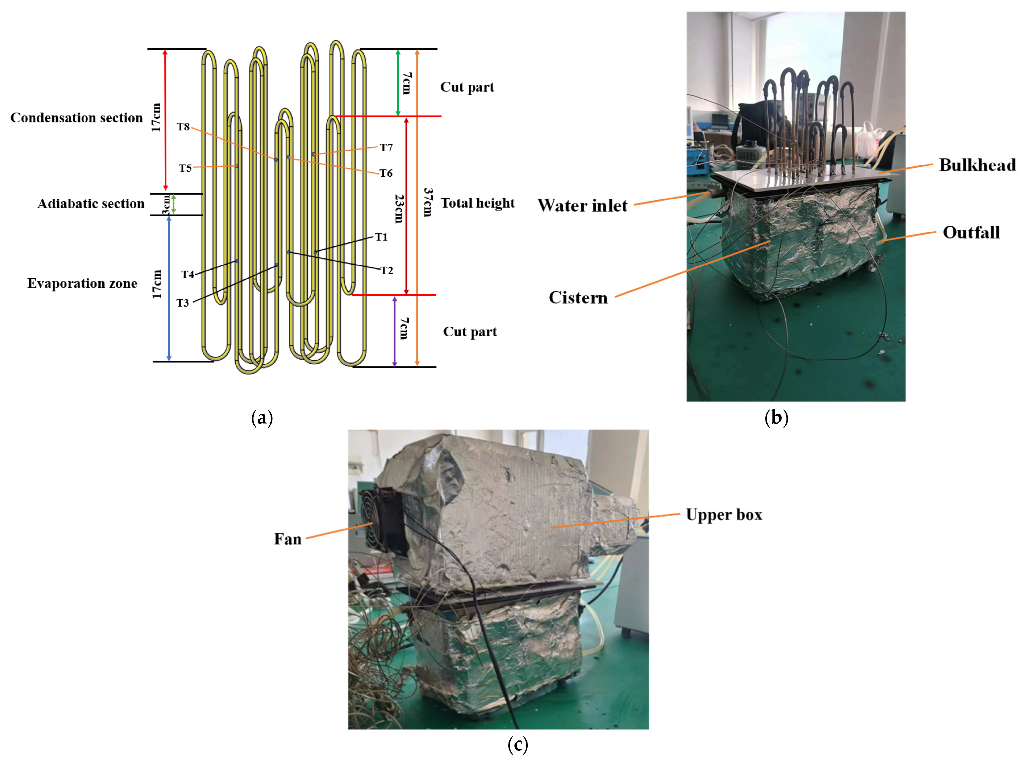
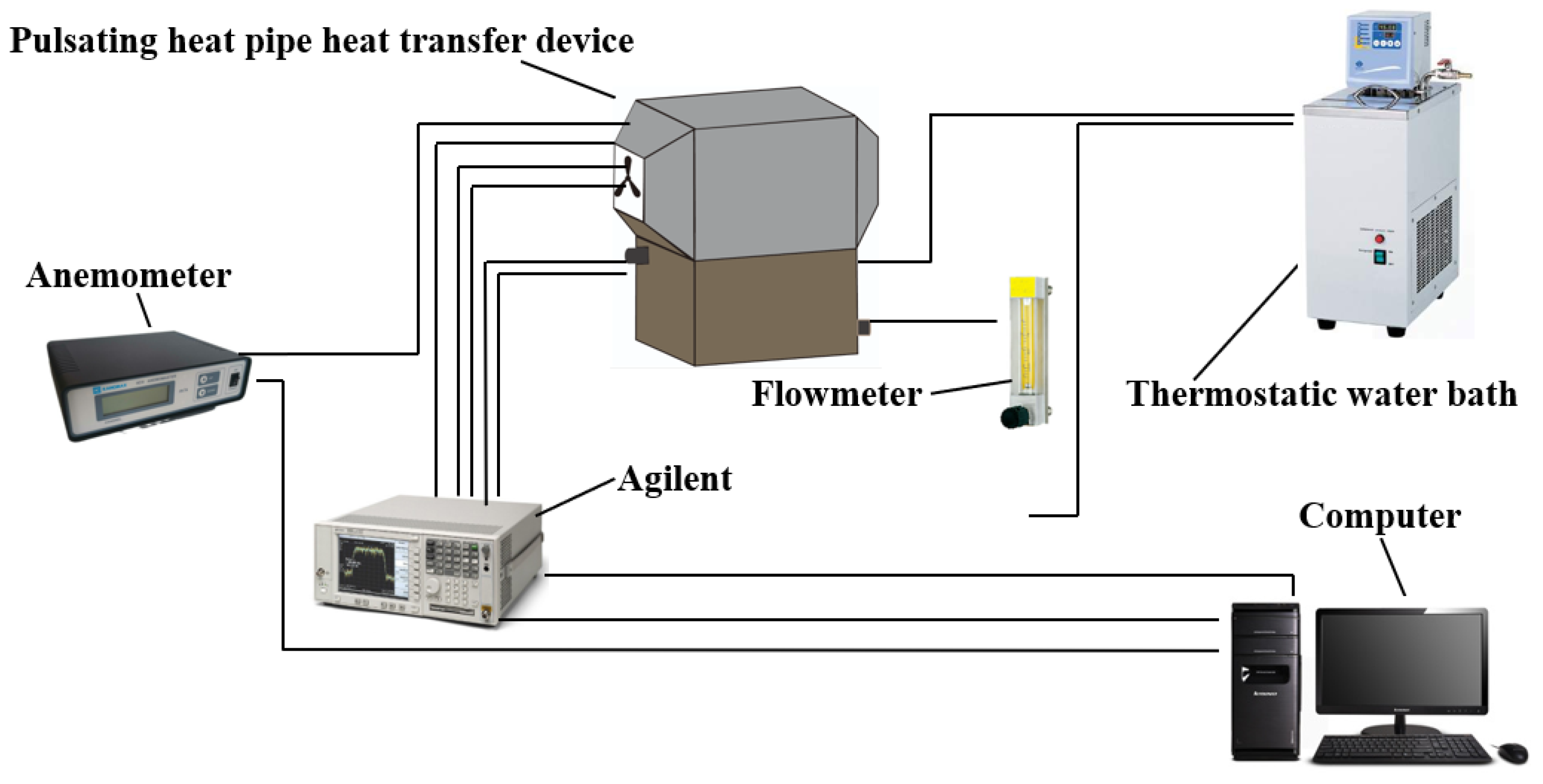
The structure of the heat-exchange unit is shown in Figure 1a, which consists of copper tubes and copper elbows formed into a closed-circulation loop by soldering. The inner diameter of each copper tube and copper elbow is 0.3 cm, and the outer diameter is 0.5 cm. As shown in Figure 1b,c, the device consists of three parts: the main body of the pulsating heat pipe, the upper box, and the lower box. The lower box passes the hot water from the thermostatic tank, and the upper box is forced by the fan to dissipate the heat by convection. Figure 2 shows the experimental system for the performance test of a pulsating-heat-pipe heat exchanger with an asymmetric structure, which consists of a pulsating-heat-pipe heat exchanger with an asymmetric structure, a data collector, a thermostatic water bath, a computer and flowmeter, and a hot-wire anemometer.
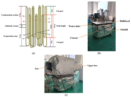
Figure 1.
Diagram of the experimental setup, where (a) is the main structure of the pulsating heat pipe, (b) is the lower-chamber structure, and (c) is the upper-chamber structure.
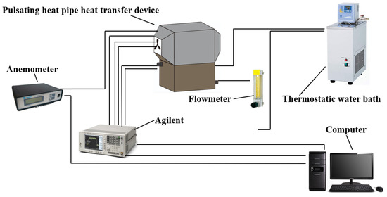
Figure 2.
Experimental system diagram.
2.2. Experimental Methods
The experimental object is an asymmetric structure of a pulsating-heat-pipe heat exchanger. Through the vacuum filling unit of the PHP first vacuum, the tube pressure is pumped to 1.8 Pa; then, the tube is filled with the corresponding proportion of distilled water with filling rates of 10%, 30%, 50%, 68%, and 80%; and finally, sealing occurs, to ensure the vacuum degree of the PHP. Each charging-rate condition was heated by five heat-source temperatures: 40 °C, 50 °C, 60 °C, 70 °C and 80 °C. The evaporation section and the condensation section were heated by a heat source of 40 °C, 50 °C, 60 °C, 70 °C and 80 °C, respectively. The evaporation section and condensation section were set up with multiple K-type thermocouples for temperature measurement, while one temperature measurement point was set up in the device at the water inlet, water outlet, air inlet, and air outlet, respectively, with an Agilent 34980A data collector for real-time temperature acquisition, with an acquisition frequency of 1 s−1 and a thermocouple temperature acquisition accuracy of ±0.05 °C.
The thermostatic water-bath system provides a heat source, and the mass flow rate of hot water in the lower chamber for import and export is controlled by a flow meter, which is kept constant at 55 L/H with a measurement accuracy of 1 L/H to ensure that the flow rate and flow rate of the water inlet and outlet of the lower chamber are equal. The condensing section adopts a fan for forced-convection heat dissipation, and a hot-wire anemometer measures the wind speed. The measured wind speed is 0.7 m/s, with an accuracy of ±0.04 m/s.
2.3. Data Processing
For the heat-transfer performance, the heat-transfer thermal resistance, the temperature difference between the heating section and the condensing section, and the equivalent thermal conductivity are used as measures, and the formulas are as follows:
Equations (1)–(4). Te and Tc are the evaporation section and the average temperature of the condensing section, K; Qe is the pulsating-heat-pipe evaporation section of the heat absorbed, W; R is the heat-transfer thermal resistance, K/W; k is the equivalent coefficient of thermal conductivity, W/(m·K); A is the total cross-sectional area of the pulsating-heat-pipe circulation pipeline, m2; and L is the pulsating-heat-pipe evaporation section and the condensing section of the average distance between the measurement point, m.
The following equation calculates the heat absorption in the evaporation section:
In Equation (5), cp is the constant-pressure specific heat capacity of the heat-source water in the evaporation section, J/(kg·K); M is the mass flow rate of the heat-source water, kg/s; and Tein and Teout are the temperatures of the water inlet and outlet, K, respectively.
2.4. Experimental Error Analysis
Since some of the errors in each measured parameter in the experiments originated from the equipment, an error analysis was carried out to more accurately evaluate the pulsating heat pipe’s heat-transfer performance. According to the law of error propagation, the measurement errors of absorbed heat, thermal resistance, and equivalent thermal conductivity in the evaporative section were calculated as follows:
The error analysis of Equations (6)–(8) yields the experimental errors of heat transfer, heat-transfer thermal resistance, and equivalent thermal conductivity in the evaporative section, which are 4.58%, 4.93%, and 5.11%, respectively.
3. Results and Analysis
3.1. Start-Up and Operating Characteristics at Different Filling Rates
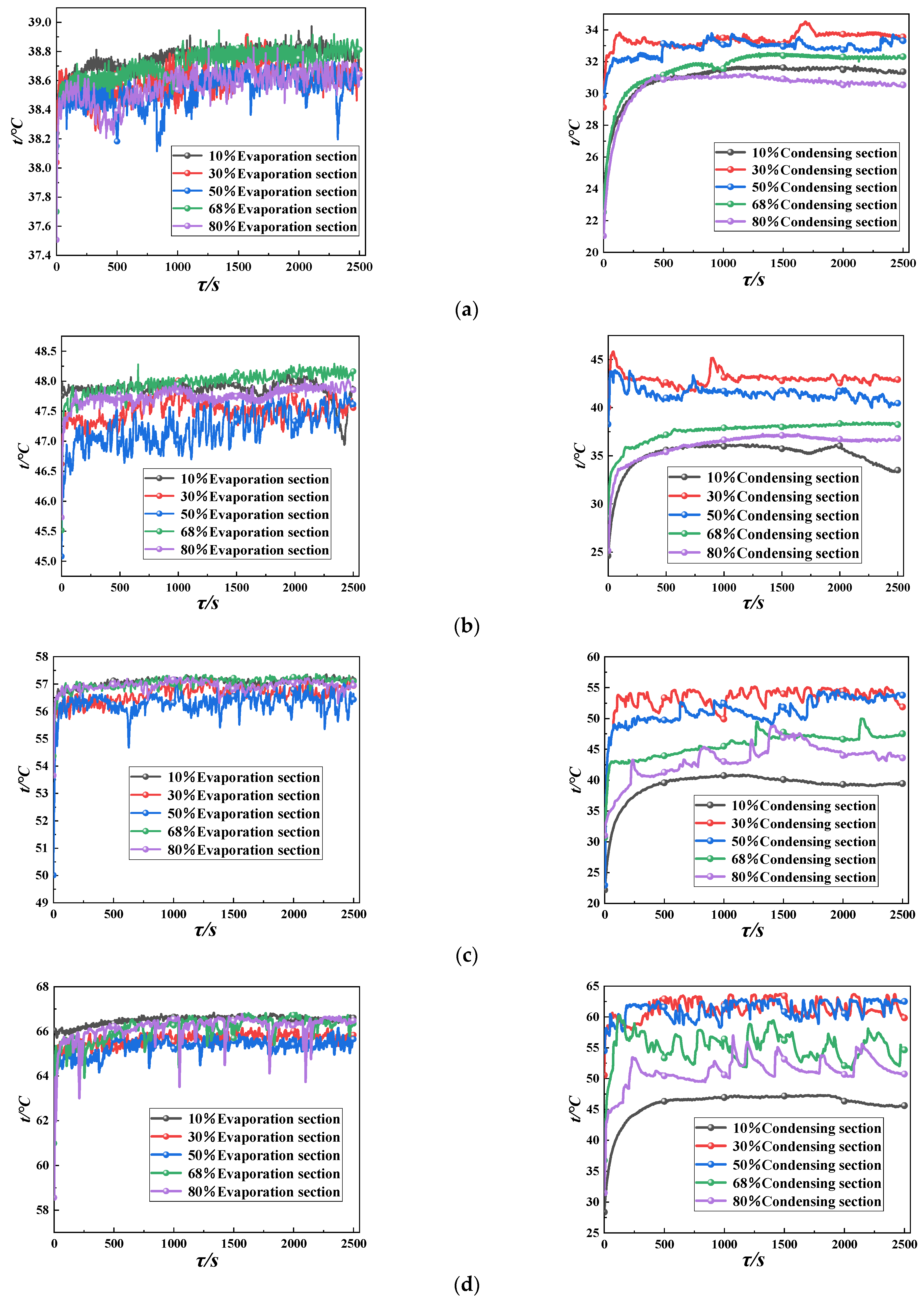
As shown in Figure 3, the wall temperature changes of the evaporating and condensing sections of the pulsating heat pipe are analyzed under different liquid filling rates. As shown in Figure 3a, when the heat source is 40 °C, the temperature curves of the evaporating section and condensing section of the pulsating heat pipe do not have any oscillation phenomenon when the liquid charging rate of the pulsating heat pipe is 10%, 68%, and 80%; the pulsating heat pipe fails to start and the temperature difference between the evaporating section and the condensing section is large, and the difference of the temperature is more than 6 °C; and the temperature curves of the evaporating section and the condensing section exhibit an oscillation phenomenon when the liquid charging rate is 30% and 50% and the pulsating heat pipe has been started—the starting time is 396 s and 503 s, respectively. When the heat pipe was started, the start-up times were 396 s and 503 s—these two liquid filling rates (of the evaporation section and the condensing section) of the temperature difference between the other three liquid filling rates, compared to the temperature difference, are smaller, and the temperature difference is 4–5 °C. This is because of the 10% low liquid-filling rate and the proportion of liquid medium in the tube being too low. However, the heat can be transferred to the condensing section through the evaporation section, it is mainly thermal conductivity-based heat transfer, the role of phase change latent heat and sensible heat in the tube is not evident, and the performance of heat transfer is poorer. This can be seen in Figure 3b–e: with the increase in the temperature of the heat source, the temperature difference between the two ends of the pulsating heat pipe become larger, and at the source of 80 °C, the temperature difference reaches 25 °C, and the difference is lower than that in the other three filling rates. At 80 °C, the temperature difference reaches 25 °C, the liquid medium is too small, the temperature of the heat source increases, leading to the phenomenon of dry burning inside the tube. Then, the heat-transfer performance of the pulsating heat pipe deteriorates, and the temperature difference between the two ends gradually increases, which does not realize the effect of efficient isothermal heat transfer. At the liquid filling rates of 30% and 50%, due to the lower temperature of the heat source, the heat provided to the evaporation section of the heat is not enough to enable the flow of the work material in the tube, and the work material in the tube remains in the start–stop–start intermittent oscillatory movement state.
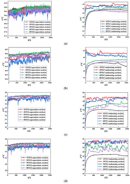
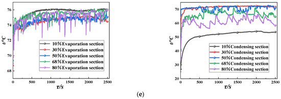
Figure 3.
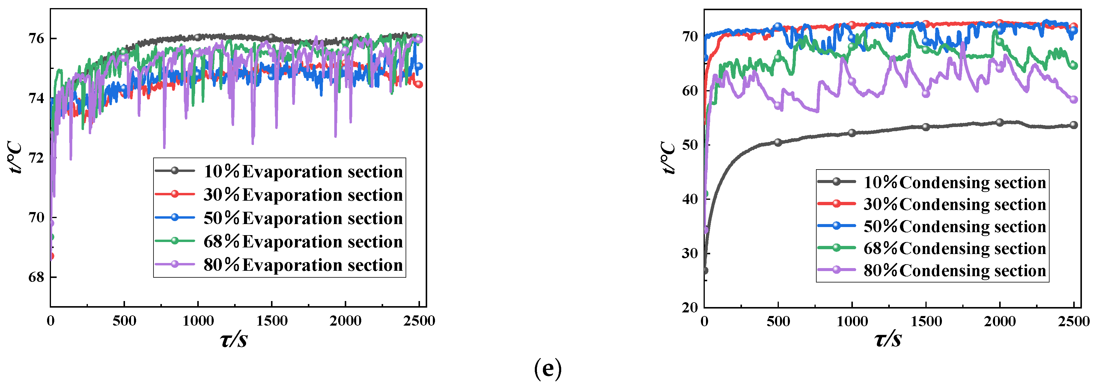
Characteristics of wall temperature change between evaporation and condensation section of pulsating heat pipe with different liquid filling rates. (a) Heat source 40 °C; (b) Heat source 50 °C; (c) Heat source 60 °C; (d) Heat source 70 °C; (e) Heat source 80 °C.
As shown in Figure 3b,c, with the increase in the heat-source temperature, except for the 10% liquid-filling rate, there is no start-up phenomenon of the pulsating heat pipe, the pulsating heat pipe starts at other liquid filling rates, and the start-up time becomes faster with the increase in the heat-source temperature. It can also be seen in the figure that with the liquid filling rate of 30% and 50%, as the heat-source temperature rises, the work material inside the tube is gradually changed from an intermittent oscillatory flow to a continuous oscillatory flow, while at the liquid filling rate of 68% and 80%, the evaporation section and the condensing section of the wall temperature began to exhibit a transient oscillatory phenomenon, but the number of oscillations is small.
This is because with the rise in the heat-source temperature at liquid filling rates of 30% and 50%, the pulsating-heat-pipe evaporation section absorbs enough heat, and the tube mass began to evaporate a large number of gas bubbles. Gas bubbles exhibit the growth and development of gas plugs in the tube, increasing the proportion of the evaporation section and the condensing section of the pressure difference between the increase in the work of the mass flow. However, at the liquid filling rate of 30%, the overall rate of filling the liquid is relatively low, the proportion of liquid plugs is small, and it is difficult to uniformly distribute the work of the mass in the tube as the liquid evaporation rate is too fast, while it is too late to condense and liquefy the gas, resulting in a large number of gas plugs in the tube. Resultingly, the oscillation of the workpiece running stability is poor, there is uneven performance, and the tube is in the mode of oscillation flow and does not reach the mode of cyclic flow. At the liquid filling rate of 50%, the liquid plugs and the proportion of gas plugs is more similar to the distribution of the workpiece between the different pipelines, and heat-transfer performance is more uniform, and in when the heat source is 60 °C, the pulsating heat pipe changes from intermittent oscillation to a stable low-frequency, small-amplitude, continuous unidirectional circulating flow after 1800s. However, the proportion of the liquid workpiece increases, and the resistance of the workpiece flow also increases, so the circulating flow rate in the whole pipe of the workpiece is low, and it needs a heat source with a higher temperature to provide the circulating driving force of the workpiece.
As for the liquid filling rates of 68% and 80%, due to the tube liquid mass being greater, it is difficult to grow the bubbles in less space. Thus, there are more small bubbles, the tube gas plug has a smaller volume, and it is difficult to produce enough pressure difference between the pulsating-heat-pipe evaporation section and condensation section to drive the mass back-and-forth oscillatory movement. The liquid plug is too large, resulting in a resistance to increase, and the tube mass often just starts and the movement of the channel will be stopped halfway. The oscillation movement of the system is subject to certain restrictions, the heat absorbed in the evaporation section is mainly transferred to the condensation section by the sensible heat between the liquid mass and the wall of the tube, the latent heat transfer is less, and the heat cannot be transferred to the condensation section through the continuous oscillation of the working fluid.
As shown in Figure 3d,e, the start-up time of the pulsating heat pipe is shortened with different liquid filling rates as the temperature of the heat source increases to 70 °C and 80 °C. At the liquid filling rates of 30% and 50%, the pulsating heat pipe in the mass reaches a stable unidirectional circulation flow, the unidirectional circulation flow stability with the heat-source temperature increases, temperature curve fluctuations are small, there is stable operation, and the temperature difference between the evaporation section and condensing section is small and gradually narrowed down to around 3 °C, close to the isothermal heat transfer. When the liquid filling rate is 68% and 80%, the pulsating heat pipe is in the mode of start–stop–start intermittent oscillation, and when the liquid filling rate is 80%, the evaporation section and condensation section of the pulsating heat pipe show a high-amplitude and low-frequency temperature oscillation curve. This is because the heat-source temperature to provide heat to the evaporation section increases, so the mass phase-transition speed and flow rate increase the mass in the evaporation section and the condensing section of the rapid phase transition between the heat; the rapid generation and growth of bubbles and the neighboring liquid plugs, combined with the pulsating-heat-pipe evaporation section and the condensing section of the differential pressure between the sections, increases; the mass driving force increases; the mass running resistance decreases; and the flow rate increases. At a large liquid-filling rate, due to the liquid mass being in a large proportion, the heat-source temperature increases, the heat absorbed by the evaporation section increases, and the mass of latent heat of the phase change and sensible heat transfer to the condensing section of the heat is greater than the medium–low rate of liquid filling. However, due to the liquid mass being more, the work of the mass of the wall—through adhesion, gravity and other kinds of resistance—to increase the density gradient caused by the driving force must be overcome by an additional force to promote the flow of the work of the mass, which is not conducive to efficient heat transfer. Even when the heat source is 80 °C, the pulsating heat pipe still exhibits the start–stop–start intermittent oscillatory movement, and the temperature difference between the evaporation section and the condensing section is still large—the temperature difference is more than 10 °C, and it is difficult to realize isothermal efficient heat transfer.
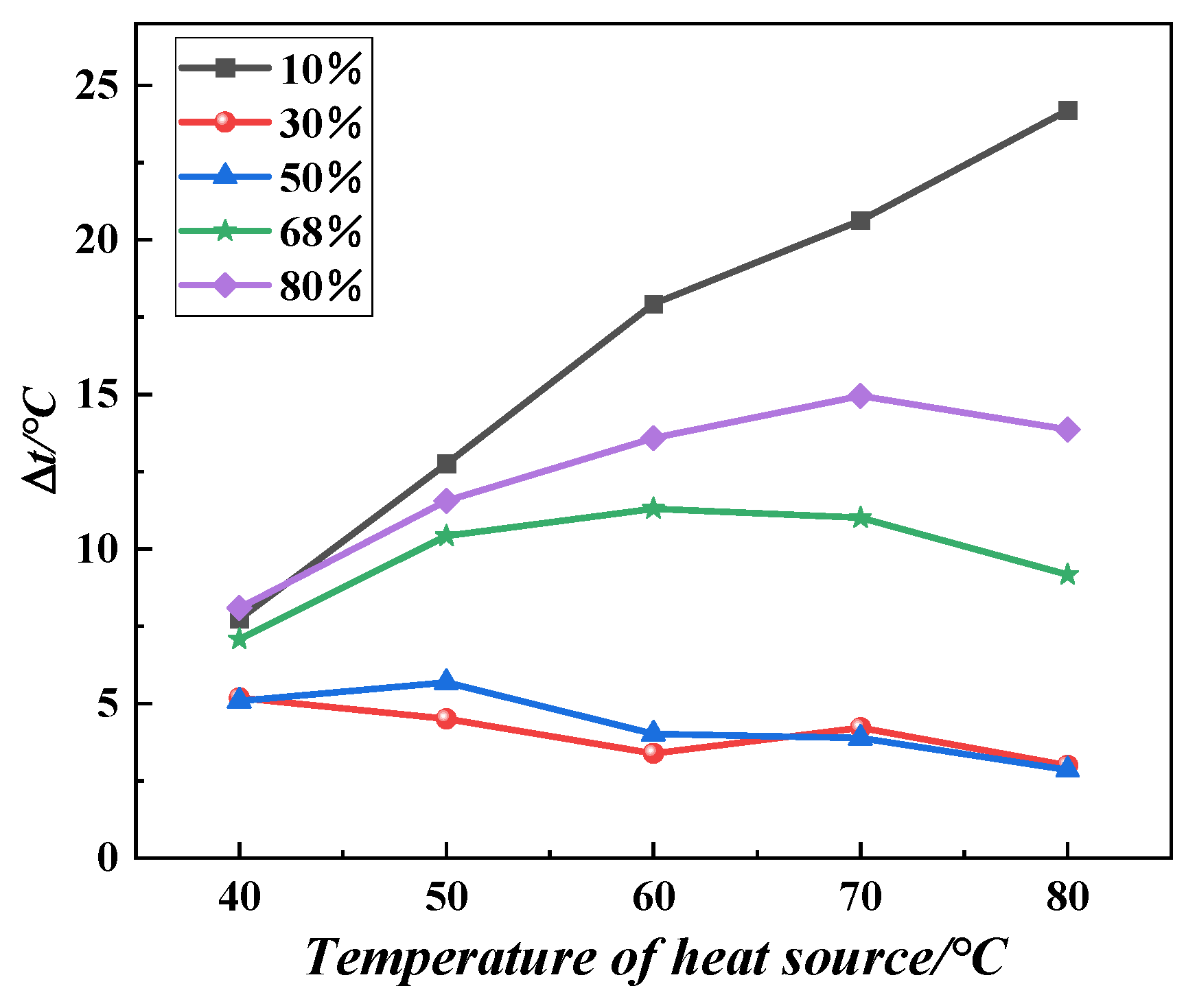
It can also be seen from the temperature-difference graph in Figure 4 that at the liquid filling rates of 10%, 68%, and 80%, the temperature difference between the evaporation section of the pulsating heat pipe and the condensing section of the temperature difference is larger, the temperature difference is more than 10 °C, the heat-transfer performance is poor, and it is difficult to achieve a small difference in the temperature of the heat transfer. At the liquid filling rates of 30% and 50%, the temperature difference between the two ends of the pulsating heat pipe are in the vicinity of 5 °C, it is easier to achieve a small difference in the temperature of the heat transfer, and the heat-transfer performance is good.
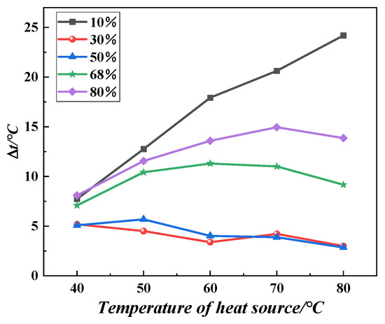
Figure 4.
Comparison of temperature difference between evaporation and condensation sections of pulsating heat pipe at different liquid filling rates.
3.2. Wavelet Frequency Analysis
The important feature of the pulsating heat pipe is its oscillatory motion. The heat transfer in the pulsating heat pipe is caused by self-excited oscillations, and the frequency of fluid pulsation plays an important role in analyzing the thermal behavior of the pulsating heat pipe. The wavelet scale diagram not only responds to the intensity of the energy oscillations of the temperature of the channel wall surface but also identifies the dominant oscillatory frequency of the oscillatory phenomenon being analyzed. In this study, Morlet wavelets are used for wavelet transform, and the wavelet function is defined by the following equation:
In Equation (9), η is the dimensionless time, ω0 is the dimensionless frequency, and the wavelet transform of the signal y(t) can be defined by the following equation [31]:
In Equation (10), a is the wavelet scale; τ is the time translation parameter, which describes the position of the wavelet in time; the superscript “*” is the conjugate complex number; Wy(a, τ) is the wavelet coefficients, and each component corresponds to a scale a and a time τ. The energy signals are normalized by dividing the wavelet coefficients by 1/, at each normalized scale, which ensures that the wavelet has the same energy at each scale.
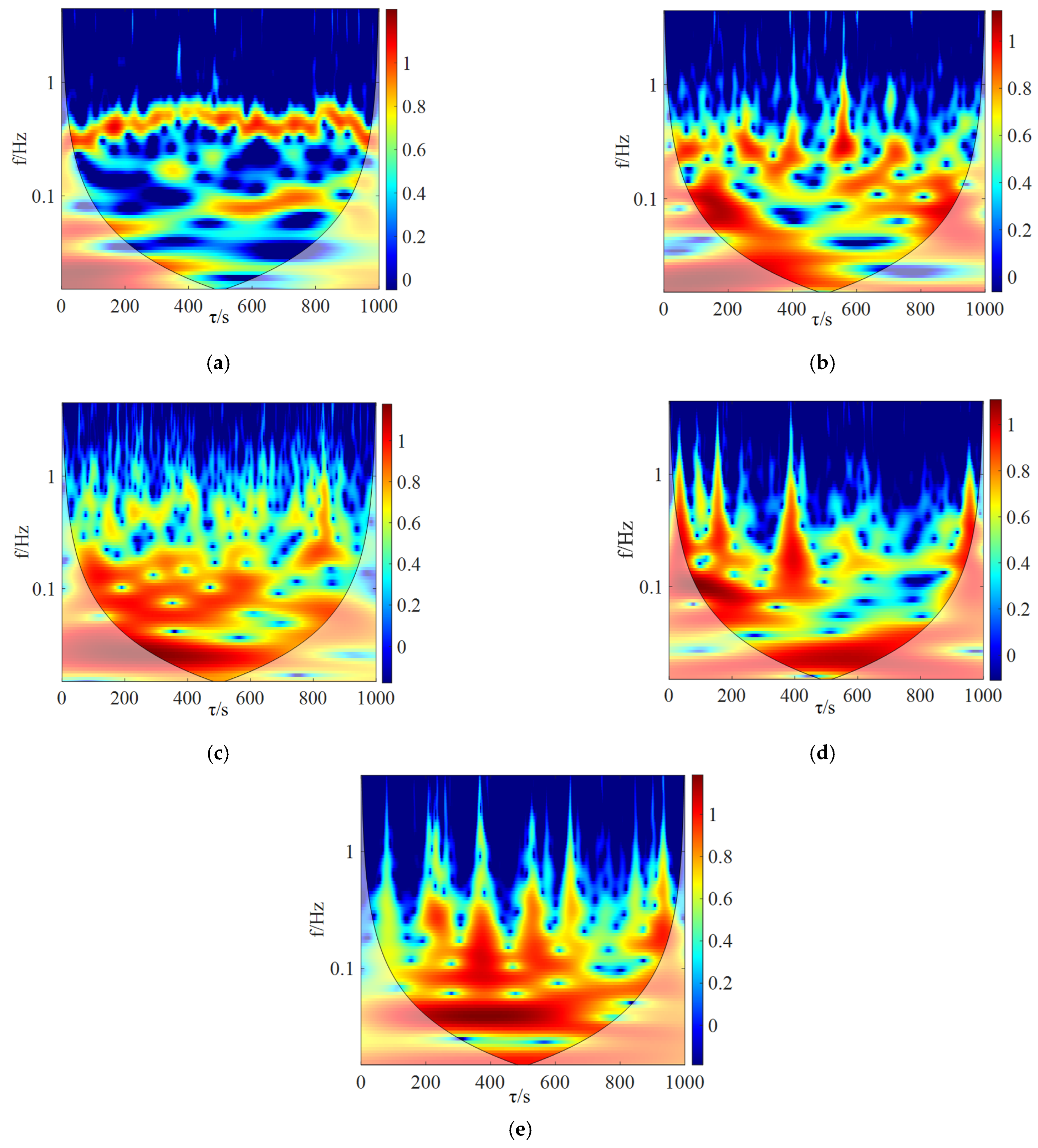
To compare the changes in the relative steady state, the temperature data of the evaporation section of the pulsating heat pipe at the 1500–2500 s under different liquid charging rates when the heat source is 80 °C are selected, and the wavelet change diagram is obtained after processing and analyzing, as shown in Figure 5. As can be seen from Figure 5a, when the liquid filling rate of the pulsating heat pipe is 10%, its oscillation frequency is low, there is no obvious pulse phenomenon, and the energy oscillation strength is weak. This indicates that under the condition of a very low liquid-filling rate, the liquid mass inside the pipe is extremely rare, and it is difficult to form gas plugs and liquid plugs to promote the movement of the mass. Also, the amount of phase-change heat transfer inside the pipe is very small, and it is mainly in the form of the thermal conductivity of the pipe wall for heat transfer.
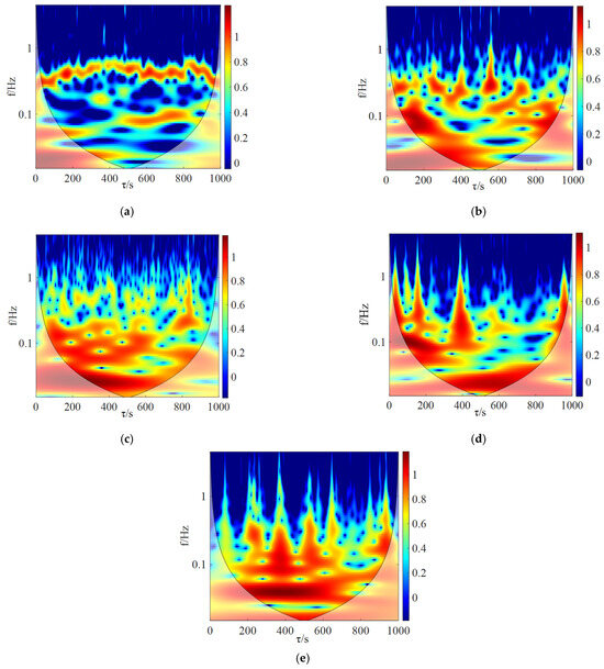
Figure 5.
Wavelet variation of the evaporation section of the pulsating heat pipe for different liquid filling rates at 80 °C of the heat source. (a) Liquefaction rate 10%; (b) Liquefaction rate 30%; (c) Liquefaction rate 50%; (d) Liquefaction rate 68%; (e) Liquefaction rate 80%.
When the liquid filling rate is increased to 30%, the sustained oscillations and energy peaks appear in the scale diagrams, indicating that the unidirectional flow in the tube has reached a sustained and stable circulation at this time. Compared with a 10% liquid-filling rate, the oscillation frequency and energy intensity of the mass in the pulsating heat pipe are improved, but even if there is continuous pulsation, the overall frequency is still low. When the liquid filling rate is 50%, as shown in Figure 5c, there are also continuous intensive high-frequency oscillations and high-energy peaks, the oscillation frequency and intensity are elevated, the pulsation phenomenon is more significant compared to the liquid filling rate of 30%, and the energy content of the temperature signal is shifted from a low-frequency value to a high-frequency value. This is because when the heat source is 80 °C, under medium 50% liquid-filling rate conditions, the pulsation of the heat pipe has enough and suitable space for bubble generation and development, and the number of liquid plugs is also appropriate; thus, the workpiece in the tube can form a relatively uniform distribution of gas–liquid plugs. At the same time, the evaporation section, the condensing section, and the adjacent tube bundle can also produce a large pressure imbalance between the driving mass in the tube, as well as faster circulation-flow heat transfer. The tube reaches a unidirectional circulation flow, the mass flow frequency is relatively high, and the mass is not easy to be burned dry, so the pulsation of the heat pipe can improve the heat-transfer performance.
At high filling rates of 68% and 80%, as shown in Figure 5d,e, the scale diagrams show that the fluid oscillates at a lower frequency, with a low frequency of about 0.2 HZ, and the diagrams show random, intermittent, high-amplitude oscillations and high energy intensity, and the high-energy peaks also correspond to pulsation phenomena in the temperature profiles. Compared to the low and medium filling rates, at a high filling rate, although the fluid flow frequency is lower, the randomly occurring oscillations are larger in amplitude and stronger in energy. This is due to the high charging rate, the liquid-phase work in the tube being more, the opportunity for bubble generation, the development of less space, and the evaporation section and condensation section making it difficult to produce a large pressure difference to promote the movement of the workpiece. Thus, the system’s oscillatory movement is subjected to a greater restriction, and the charging rate increases with the increase in the pulsation of the heat-pipe gravity. The wall friction and other resistance are also increased, which prevents the workpiece oscillatory movement, resulting in the dominant workpiece fluids. The oscillation frequency is low, and the pulsating heat pipe, despite the start, can still be in the start–stop–start intermittent oscillation state. However, there is more liquid-phase work in the tube, resulting in phase-change latent heat and sensible heat absorption. The release of the heat transferred is also large, and it is not easy for the tube to burn dry, so there is a higher amplitude and energy of the stochastic, intermittent oscillation.
3.3. Heat-Transfer Performance Indexes at Different Filling Rates
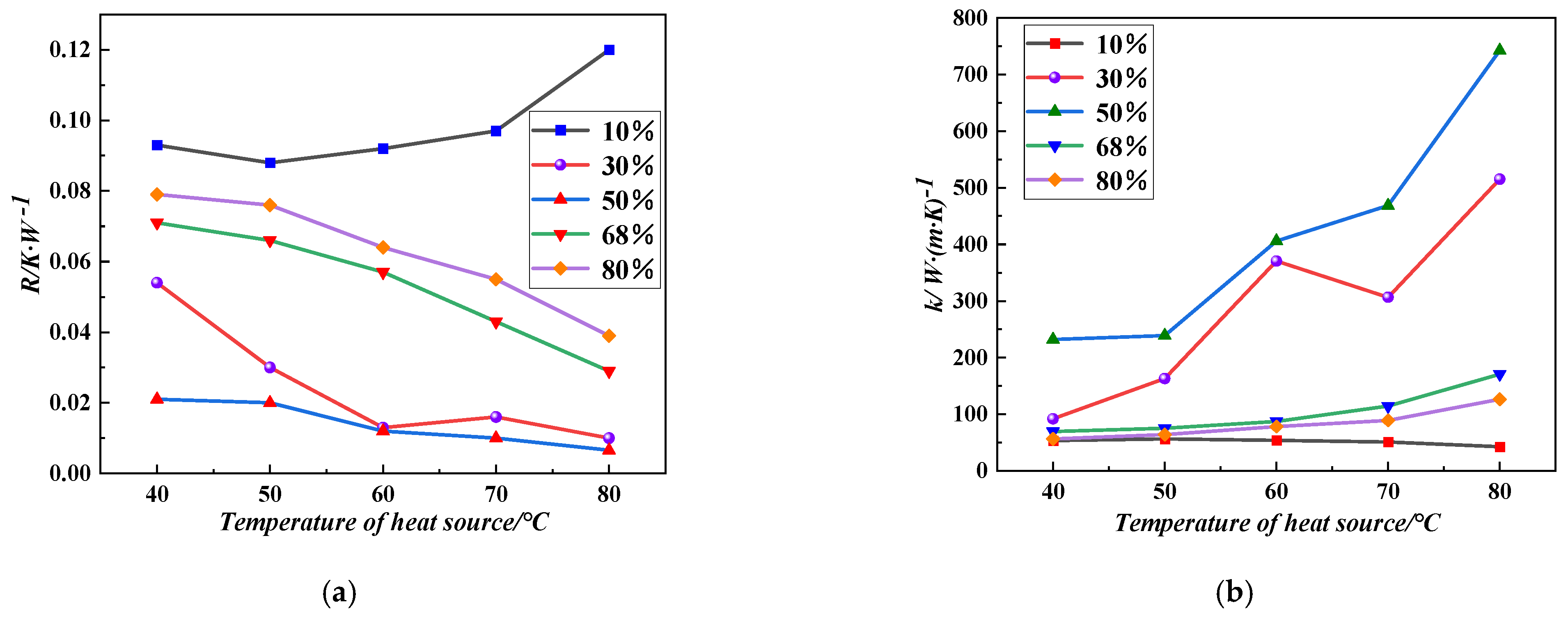
Figure 6a,b shows the variation of thermal resistance and equivalent thermal conductivity with the temperature of the heat source for different fluid filling rates. From Figure 6, it can be seen that when the liquid filling rate is 10%, the overall trend of the thermal resistance of the pulsating heat pipe increases with the increase in the temperature of the heat source, and when the temperature of the heat source is 50 °C, its thermal resistance has the smallest value of 0.088 K/W, while the equivalent thermal conductivity is the largest of 56.06 W/(m·K). When the liquid filling rate is 30%, the overall trend of thermal resistance decreases, but when the heat source is 70 °C, the thermal resistance slightly increases to 0.016 K/W, and the equivalent thermal conductivity decreases to 306.60 W/(m·K), while the thermal resistance reaches the minimum and the equivalent thermal conductivity reaches the maximum when the heat source is 80 °C. At other liquid filling rates, the thermal resistance and equivalent thermal conductivity of the pulsating heat pipe decreased and increased with the increase in the heat-source temperature. Especially at 80 °C, the heat-transfer performance of the pulsating heat pipe was the best when the liquid filling rate was 50%, with the smallest value of thermal resistance and the largest equivalent thermal conductivity. The heat-transfer performance was the worst, with the largest value of thermal resistance and the smallest equivalent thermal conductivity, when the liquid filling rate was 10%, no matter the heat-source temperature.
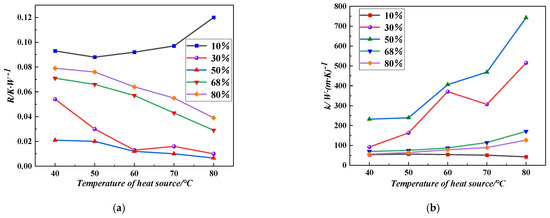
Figure 6.
Variation of thermal resistance and equivalent thermal conductivity with heat-source temperature for different liquid filling rates. (a) Thermal resistance; (b) Equivalent thermal conductivity.
This is due to the 10% liquid-filling rate leading to too little liquid work in the tube, too many gas plugs, no formation of an effective uniform distribution of liquid plugs and gas plugs in the tube, the gas occupying almost all the space in the tube, the sensible heat and phase-change latent heat transfer of the heat being too low—mainly thermal conductivity-type heat transfer. Moreover, the liquid plugs cannot effectively take away the heat of the evaporation section, resulting in the evaporation of the section of the temperature being high, the return to the evaporation of the section of the liquid being low, the evaporation end exhibiting the burning dry phenomenon and being unable to form a continuous oscillation, the condensing section temperature being lower, the temperature difference between the two ends being larger, the temperature difference being more than 20 °C, the heat-transfer performance deteriorating, and the inability to realize isothermal heat transfer. With the liquid filling rate increased to 30–50%, the tube-liquid gas plug distribution gradually tends to be uniform. When the heat-source temperature increases, the workpiece running resistance decreases, the formation of bubbles in the evaporating end and expansion speed up, the pressure difference between the evaporation section and the condensing section increases, the driving force increases, the flow state from the oscillating flow moves into a unidirectional circulation flow, and the pulsation of the heat pipe heat-transfer performance improves. At the 30% liquid-filling rate, the heat source was 70 °C when the heat-transfer performance decreased because of the relatively small amount of liquid mass in the tube. Then, the heat-source temperature increased, the evaporation section became prone to the local evaporation phenomenon, and the condensate reflux was not timely, resulting in a decline in the performance of the heat transfer. However, when the heat-source temperature further increased, the circulation of the mass in the tube flow rate is accelerated, the condensate can exhibit timely reflux, and the pulsation of the heat-pipe heat-transfer performance is again elevated.
At the liquid filling rates of 68% and 80%, the liquid mass in the tube is greater, although the tube does not easily exhibit the burn-dry phenomenon, the tube space is not conducive to the generation and development of bubbles, it is difficult for the evaporation section and the condensing section to produce a large pressure difference to promote the movement of the mass, the system’s oscillatory motion is more limited, and the liquid filling rate increases with the pulsating-heat-pipe gravity. Moreover, wall friction and other resistance also increase and there is need for higher heat-source temperature to drive the mass movement, so the thermal resistance and thermal conductivity equivalent to the rise in heat-source temperature decrease and increase, and the heat-transfer performance rises. A higher heat-source temperature drives the workpiece movement, so for the thermal resistance and equivalent thermal conductivity, with the increase and reduction in heat-source temperature, heat-transfer performance rises.
4. Conclusions
In this paper, an in-depth comparative analysis of the heat-transfer performance of pulsating-heat-pipe heat exchangers with asymmetric structures is carried out from multiple perspectives of startup, operation, and thermal performance based on different heat sources and different liquid filling rates, and the following conclusions are drawn:
(1) As the temperature of the heat source rises, the pulsating heat pipe is prone to drying out, and the heat-transfer performance deteriorates at a very low liquid-filling rate of 10%. With the increase in liquid filling rate, the pulsating-heat-pipe start-up time increases. Especially at the high 68% and 80% liquid-filling rates, it is difficult to start and run the workpiece, the workpiece movement resistance is larger, the movement is limited, the effect of oscillation is poor, and it is necessary for the 80 °C heat-source temperature to be higher than the source of the workpiece to provide operating power. At the 10%, 68%, and 80% liquid-filling rates, the temperature difference between the pulsating-heat-pipe evaporation section and the condensing section is larger, the temperature difference is between 10–25 °C, and it is difficult to achieve isothermal heat transfer. At the 30% and 50% liquid-filling rates, the pulsating-heat-pipe oscillation effect is excellent, the temperature difference between the evaporation section and condensation section is small, and the temperature difference is about 3 °C. At these two liquid-filling rates, it is easier for the pulsating heat pipe to realize isothermal heat transfer.
(2) When the heat source is 80 °C, the fluid flow-oscillation frequency is the highest and the heat-transfer performance is the best in the pulsating heat pipe under the 50% filling rate. At the low and high liquid-filling rates, the fluid mass-oscillation flow frequency is low, the mass is difficult to run, and the heat-transfer performance is poor.
(3) As the temperature of the heat source increases, the overall thermal resistance tends to increase when the liquid filling rate is 10%, but the thermal resistance is the smallest at the heat source of 50 °C, at 0.088 K/W, and the equivalent thermal conductivity is the largest, at 56.06 W/(m·K). At other liquid filling rates, the thermal resistance and equivalent thermal conductivity decreased and increased with the increase in temperature of the heat source. The overall heat-transfer performance of the pulsating heat pipe is the best when the liquid filling rate is 50%, with the smallest thermal resistance and the largest equivalent thermal conductivity compared with the other filling rates, while the liquid filling rate of 30% has a good heat-transfer performance overall but the thermal resistance increases to 0.016 K/W, the equivalent thermal conductivity decreases, and the heat-transfer performance becomes weaker when the heat source is 70 °C. The thermal resistance and the equivalent thermal conductivity decrease with the increase in heat-source temperature, and the heat-transfer performance becomes weaker.
Author Contributions
Experimental manipulation, D.L., K.Y. and C.Z.; data collection, X.C.; data analysis, J.L. and D.L.; writing, D.L.; review and supervision, J.L. and F.S. All authors have read and agreed to the published version of the manuscript.
Funding
This work was supported by the Science and Technology Development Program of Jilin Provincial Department of Science and Technology in 2024: Research on Key Technologies for Efficient Heat Dissipation of High Power LED Lighting Equipment in Urban Public Areas (20240304101SF), the Project of Jilin Provincial Department of Education in 2024: Research on Key Technologies for Efficient Heat Dissipation of Ultra-High Energy Density LED Lighting (JJKH20240789KJ), and the Project of Jilin Provincial Science and Technology Development Program in 2024: Research on the Synergistic Mechanisms of Pulsating Heat Pipes in Enhancing the Heat Transfer Processes for Energy Loads with Different Characteristics (YDZJ202401324ZYTS).
Data Availability Statement
All relevant data are within the paper.
Acknowledgments
We are grateful to our laboratory colleagues for their important technical assistance, and to the Jilin Provincial Department of Science and Technology and the Department of Education for their financial support.
Conflicts of Interest
The authors declare no conflict of interest.
Nomenclature
| A | the total cross-sectional area of the pulsating heat pipe circulation pipeline, [m2] | W | wavelet transform |
| a | wavelet scale | y | signal |
| i | imaginary part | η | non-dimensional time |
| L | the pulsating heat pipe evaporation section and the condensing section of the average distance between the measurement point, [m] | τ | time, s |
| Qe | the pulsating heat pipe evaporation section of the heat absorbed, [W] | ψ | wavelet mother |
| R | the heat transfer thermal resistance, [K/W] | ω0 | Non-dimensional frequency |
| Tc | the average temperature of the condensing section, [K] | k | the equivalent coefficient of thermal conductivity, W/(m·K) |
| Te | the average temperature of the evaporation section, [K] |
References
- Ling, Y.; Li, X.; Zhang, X.; Liu, Z.; Zhao, P. Experimental and Theoretical Study on Operation Characteristics of an Oscillating Heat Pipe. Appl. Sci. 2023, 13, 8479. [Google Scholar] [CrossRef]
- Liu, Y.; Bao, K.; Yan, Y.; Ouyang, H.; Han, X. Investigation on the Influence of Different Heat Transmission Distances on Thermo-Hydrodynamic Characteristics of Pulsating Heat Pipes. Appl. Therm. Eng. 2023, 234, 121284. [Google Scholar] [CrossRef]
- Rajale, M.J.; Prasad, P.I.; Rao, B.N. A Review on the Heat Transfer Performance of Pulsating Heat Pipes. Aust. J. Mech. Eng. 2023, 21, 1658–1702. [Google Scholar] [CrossRef]
- Yu, J.; Hong, S.; Koudai, S.; Dang, C.; Wang, S. An Experimental Investigation on the Heat Transfer Characteristics of Pulsating Heat Pipe with Adaptive Structured Channels. Energies 2023, 16, 6988. [Google Scholar] [CrossRef]
- Li, J.; Qiao, L.; Chen, M.; Zeng, X. Research on Performance Test and Evaluation of Thermal Management System of Power Battery Module under Harsh Conditions. Appl. Therm. Eng. 2024, 241, 122406. [Google Scholar] [CrossRef]
- Chung, W.-S.; Lee, J.-S.; Rhi, S.-H. Thermal Management System Using Pulsating Heat Pipe of Cylindrical Battery Cell. J. Mech. Sci. Technol. 2023, 37, 6711–6725. [Google Scholar] [CrossRef]
- Lv, W.; Li, J.; Chen, M. Experimental Study on the Thermal Management Performance of A Power Battery Module with A Pulsating Heat Pipe under Different Thermal Management Strategies. Appl. Therm. Eng. 2023, 227, 120402. [Google Scholar] [CrossRef]
- Wang, C.; Yuan, K.; Song, Q.; Yu, J.; Yang, J.; Qu, J.; Zhu, Y. Performance of Pulsating Heat Pipe with A Stimulus of Auxiliary Heat Load for Battery Thermal Management System. Int. J. Heat Mass Transf. 2024, 223, 125190. [Google Scholar] [CrossRef]
- Pandey, N.; Naresh, Y. A Comprehensive 4E (Energy, Exergy, Economic, Environmental) Analysis of Novel Pyramid Solar Still Coupled with Pulsating Heat Pipe: An Experimental Study. Renew. Energy 2024, 225, 120227. [Google Scholar] [CrossRef]
- Hemmatian, A.; Kargarsharifabad, H.; Esfahlani, A.A.; Rahbar, N.; Shoeibi, S. Improving Solar Still Performance with Heat Pipe/Pulsating Heat Pipe Evacuated Tube Solar Collectors and PCM: An Experimental and Environmental Analysis. Sol. Energy 2024, 269, 112371. [Google Scholar] [CrossRef]
- Liu, S.; Yang, Y.; Ma, K.; Jin, H.; Jin, X. Experimental Study of Pulsating Heat Pipes Filled with Nanofluids under the Irradiation of Solar Simulator. Energies 2022, 15, 9153. [Google Scholar] [CrossRef]
- Mahajan, G.; Thompson, S.M.; Cho, H. Energy and Cost Savings Potential of Oscillating Heat Pipes for Waste Heat Recovery Ventilation. Energy Rep. 2017, 3, 46–53. [Google Scholar] [CrossRef]
- Yang, H.; Wang, J.; Wang, N.; Yang, F. Experimental Study on A Pulsating Heat Pipe Heat Exchanger for Energy Saving in Air-Conditioning System in Summer. Energy Build. 2019, 197, 1–6. [Google Scholar] [CrossRef]
- Deng, Z.; Zheng, Y.; Liu, X.; Zhu, B.; Chen, Y. Experimental Study on Thermal Performance of an Anti-Gravity Pulsating Heat Pipe and Its Application on Heat Recovery Utilization. Appl. Therm. Eng. 2017, 125, 1368–1378. [Google Scholar] [CrossRef]
- Xu, Y.; Xue, Y.; Cai, W.; Qi, H.; Li, Q. Experimental Study on Performances of Flat-Plate Pulsating Heat Pipes without and with Thermoelectric Generators for Low-Grade Waste Heat Recovery. Appl. Therm. Eng. 2023, 225, 120156. [Google Scholar] [CrossRef]
- Qu, J.; Wu, H.-Y.; Wang, Q. Experimental Investigation of Silicon-Based Micro-Pulsating Heat Pipe for Cooling Electronics. Nanoscale Microscale Thermophys. Eng. 2012, 16, 37–49. [Google Scholar] [CrossRef]
- Dang, C.; Jia, L.; Lu, Q. Investigation on Thermal Design of A Rack with the Pulsating Heat Pipe for Cooling CPUs. Appl. Therm. Eng. 2017, 110, 390–398. [Google Scholar] [CrossRef]
- Mito, T.; Natsume, K.; Yanagi, N.; Tamura, H.; Tamada, T.; Shikimachi, K.; Hirano, N.; Nagaya, S. Development of Highly Effective Cooling Technology for A Superconducting Magnet Using Cryogenic OHP. IEEE Trans. Appl. Supercond. 2010, 20, 2023–2026. [Google Scholar] [CrossRef]
- Hosseini, S.M.J.; Ranjbar, A.A.; Sedighi, K.; Rahimi, M. Melting of Nanoprticle-Enhanced Phase Change Material Inside Shell and Tube Heat Exchanger. J. Eng. 2013, 2013, 784681. [Google Scholar] [CrossRef]
- Kammuang-Lue, N.; Patanathabutr, C.; Sakulchangsatjatai, P.; Terdtoon, P. Thermal Characteristics of Rotating Closed-Loop Pulsating Heat Pipe Designed for Rotating-Type Energy Storage Devices. Energy Rep. 2022, 8, 302–308. [Google Scholar] [CrossRef]
- Charoensawan, P.; Wilaipon, P.; Seehawong, N. Flat Plate Solar Water Heater with Closed-Loop Oscillating Heat Pipes. Therm. Sci. 2021, 25 Pt A, 3607–3614. [Google Scholar] [CrossRef]
- Sarafraz, M.M.; Hormozi, F. Experimental Study on the Thermal Performance and Efficiency of a Copper Made Thermosyphon Heat Pipe Charged with Alumina–Glycol Based Nanofluids. Powder Technol. 2014, 266, 378–387. [Google Scholar] [CrossRef]
- Slobodeniuk, M.; Bertossi, R.; Ayel, V.; Ravichandran, R.; Thyagarajan, K.; Romestant, C.; Bertin, Y. Experimental Study of the Flat Plate Pulsating Heat Pipe Operation During Dry-Out and Flow Re-Activation Periods under Microgravity Conditions. Int. J. Multiph. Flow 2022, 147, 103888. [Google Scholar] [CrossRef]
- Zhao, X.; Su, L.; Jiang, J.; Deng, W.; Zhao, D. A Review Of Working Fluids and Flow State Effects on Thermal Performance of Micro-Channel Oscillating Heat Pipe for Aerospace Heat Dissipation. Aerospace 2023, 10, 179. [Google Scholar] [CrossRef]
- Ayel, V.; Pagliarini, L.; Veer, T.V.; Slobodeniuk, M.; Bozzoli, F.; Romestant, C.; Bertin, Y. Experimental Analyses of Temperature and Pressure Oscillation Frequencies of a Flat Plate Pulsating Heat Pipe Tested under Various Edge Orientation Angles and Heat Loads. Exp. Comput. Multiph. Flow 2024, 6, 253–264. [Google Scholar] [CrossRef]
- Wu, M.; Ji, Y.; Feng, Y.; Liu, H.; Yang, X. Experimental Study on the Effects of Filling Ratios on Heat Transfer Characteristics of Liquid Metal High-Temperature Oscillating Heat Pipes. Int. J. Heat Mass Transf. 2023, 209, 124153. [Google Scholar] [CrossRef]
- Fan, Y.; Wang, Z.; Guo, J.; Ma, D.; Yang, W. Capture of Kinetic Behavior of Ethanol-Based Copper Oxides in Pulsating Heat Pipe. Int. J. Heat Mass Transf. 2024, 225, 125392. [Google Scholar] [CrossRef]
- Jang, D.S.; Lee, J.S.; Ahn, J.H.; Kim, D.; Kim, Y. Flow Patterns and Heat Transfer Characteristics of Flat Plate Pulsating Heat Pipes with Various Asymmetric and Aspect Ratios of the Channels. Appl. Therm. Eng. 2017, 114, 211–220. [Google Scholar] [CrossRef]
- Patel, E.D.; Kumar, S. Thermal Performance of a Single Loop Pulsating Heat Pipe with Asymmetric Adiabatic Channel. Appl. Therm. Eng. 2023, 219, 119541. [Google Scholar] [CrossRef]
- Shukla, A.K.; Patel, E.D.; Kumar, S. Study of an Asymmetric Dual Loop Pulsating Heat Pipe: Visualization and Parametric Analysis. Appl. Therm. Eng. 2024, 245, 122842. [Google Scholar] [CrossRef]
- Cattani, L.; Vocale, P.; Bozzoli, F.; Malavasi, M.; Pagliarini, L.; Iwata, N. Global and Local Performances of a Tubular Micro-Pulsating Heat Pipe: Experimental Investigation. Heat Mass Transf. 2022, 58, 2009–2027. [Google Scholar] [CrossRef]
Disclaimer/Publisher’s Note: The statements, opinions and data contained in all publications are solely those of the individual author(s) and contributor(s) and not of MDPI and/or the editor(s). MDPI and/or the editor(s) disclaim responsibility for any injury to people or property resulting from any ideas, methods, instructions or products referred to in the content. |
© 2024 by the authors. Licensee MDPI, Basel, Switzerland. This article is an open access article distributed under the terms and conditions of the Creative Commons Attribution (CC BY) license (https://creativecommons.org/licenses/by/4.0/).

