Abstract
This article proposes a heating method based on heat pump technology to address the large amount of low-grade waste heat generated by a certain type of ultra-high voltage direct current (UHVDC) converter valve. Thermal performance calculations for two systems, a basic vapor compression heat pump system (BVCHPS) based on thermal expansion valve throttling and an ejector-enhanced heat pump system (EEHPS) are analyzed. The research results show that the EEHPS exhibits superior COP and exergy efficiency when generating hot water above 80 °C using a heat source below 50 °C. Additionally, mathematical modeling analysis identifies optimal structural parameters such as nozzle throat diameter, throat area ratio, and nozzle outlet diameter for the ejector in its design state. The low-temperature waste heat recovered from the UHVDC converter valves can be further used in engineering applications such as heating, refrigeration, seawater desalination, and sewage treatment.
1. Introduction
The converter valve is the core equipment of ultra-high voltage direct current (UHVDC) transmission engineering, and its components will withstand large current and voltage stress during operation, thereby generating high heat. To ensure the safe operation of the converter valve, it is necessary to dissipate the heat through a cooling system. At present, the valve cooling system of the converter station mainly includes two parts: the internal cold water circulation system and the external valve cooling system. The heat generated by the converter valve is discharged to the environment through the air cooler/closed tower [1,2]. Figure 1 shows the average temperature and average waste heat measurement results in the cooling water circulation system of a converter valve in China in 2022.
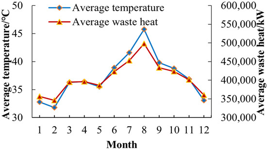
Figure 1.
Operating data of average temperature and average waste heat of a certain converter valve in China.
As shown in Figure 1, the average temperature of the cooling water outlet of the converter valve is below 50 °C throughout the year, while the residual heat is above the megawatt level. To effectively utilize this low-grade high-power heat, it is necessary to use heating technology to improve it to a higher energy grade (above 80 °C) before achieving effective utilization. Therefore, heat pump systems are a good means of achieving this goal.
Figure 2 shows a schematic diagram of the waste heat comprehensive utilization system of the converter valve. It mainly includes three parts: the converter valve water-cooling system, the jet expansion heat pump system (described in Section 2.1.2), and the waste heat application system. The waste heat utilization system can be used in scenarios such as heating, refrigeration, wastewater treatment, and seawater desalination. For example, in winter, the low-grade waste heat generated by the converter valve is upgraded to a high-grade heat source through a heat pump system to meet the heating needs of the building. In summer, high-grade waste heat can drive the lithium bromide absorption refrigeration system to achieve refrigeration. In the field of water treatment, this system can use methods such as mechanical vapor distillation to achieve seawater desalination or sewage treatment. The full system analysis will be further demonstrated in future work and will not be elaborated here.
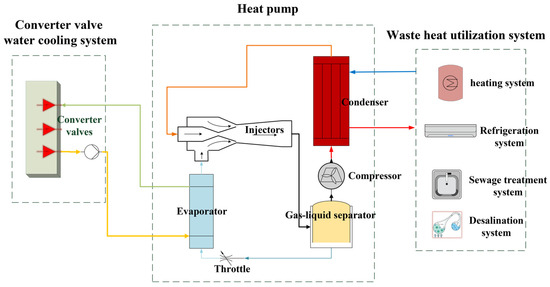
Figure 2.
Converter valve residual heat utilization system.
At present, basic vapor compression heat pump systems (BVCHPS) are often used to improve the temperature and grade of waste heat recovery. However, the BVCHPS uses a capillary tube or a throttle valve to expand the working fluid leaving the high-pressure condenser. In the BVCHPS, the high-pressure saturated or supercooled liquid from the condenser must be maintained at a low temperature through pressure reduction equipment, such as a throttle valve and capillary tube. This process is frequently an isoenthalpic rather than an isentropic process, which results in the generation of a considerable quantity of flash steam. The flash steam does not absorb heat but rather consumes work, which ultimately leads to throttling loss. This component of energy loss represents a significant proportion of the total energy loss of the refrigeration system, accounting for more than 10%.
Compared with the ideal refrigeration cycle, also known as the reverse Carnot cycle, the expansion process causes thermodynamic loss called throttling loss, where expansion energy is entirely dissipated through friction [3,4]. Harrell et al. [5] used an R-134a two-phase ejector and the test rig to estimate the COP of the refrigeration cycle. It was found that the COP improvement ranged from 3.9% to 7.6%. To fully utilize the energy during the throttling and depressurization process, an ejector-enhanced heat pump system (EEHPS) is studied to reduce throttling and depressurization losses. So, as a key component of the EEHPS, the ejector has the characteristics of a simple physical structure, low manufacturing cost, no movable parts, long service life, and high reliability [6].
There are many reports on the research of the EEHPS. K.J. Chua et al. [7] overviewed an ejector-compression heat pump that could improve the COP up to 21% over the BVCHPS depending on the geometrical, aerodynamical, and mechanical design of the ejector. Gagan et al. [8] experimented with an ejection refrigeration system driven with a low-grade heat source with a temperature below 60 °C. The refrigerant R-1234ze(E) was used as a working fluid. The coefficient K, which can be considered as the overall loss coefficient, is presented and discussed. The experiments show that for all the cases, the coefficient K exceeds 0.70 and the ejector efficiency is up to 0.27. Li et al. [9] studied an ejector-enhanced dual-temperature air-source heat pump cycle that can provide hot water at 60 °C and 35 °C simultaneously. The coefficient of performance and exergy efficiency of the presented systems can be improved by 30.30–52.38% and 53.85–92.75%, respectively, for two ternary azeotropic mixtures (R1234yf + R134a + R152a, R600a + R1234ze(E) + R13I1) and pure refrigerant R134a. Zou et al. [10] proposed a solar-enhanced ejector expansion heat pump (SEEHP) cycle. Results showed that, compared to the conventional ejector expansion heat pump cycle, the SEEHP with R134a refrigerant has a 23.64–39.82% increase in the heating coefficient of performance (COPh) for the given condensing temperature range. Zhao et al. [11] presented a modified sub-cooler vapor injection (MSV) cycle with an ejector for air source heat pump applications. The results show that compared with the basic sub-cooler vapor-injection cycle, the heating coefficient of performance (COPh) and the exergy efficiency of the MSV cycle are increased by 10.1% and 14.1% under typical operating conditions, respectively. The COPh of the MSV cycle using three low-GWP substitutes (R1234yf, R1234ze(E), and R32) are compared with R134a. The results indicate that among them, R1234ze(E) is the most promising refrigerant for improving MSV cycle performance while replacing R134a. Al-Sayyab et al. [12] studied a compound photovoltaic thermal waste heat-driven ejector-heat pump system. Eleven lower global warming potential (GWP) refrigerants are compared. The results show that the cooling coefficient of performance enhancement ranges from 15% to 54% compared with a traditional R134a heat pump and R515B has the lowest exergy destruction, with the highest exergy efficiency of all investigated refrigerants. Wang et al. [13] studied an ejector-enhanced vapor injection cycle (EVIC) for air-source heat pumps. Simulated results show that the EVIC with R22, R290, and R32 have a 2.6–3.1%, 3.2–3.7%, and 2.9–3.1% improvement in coefficient of performance (COP) and a 6.0–8.4%, 7.3–10.2%, and 6.7–8.2% improvement in volumetric heating capacity compared with those of the basic vapor injection cycle under the same given operating conditions.
Although there has been a lot of research on the BVCHPS and EEHPS, to our knowledge, there has been no previous experimental or theoretical analysis on the application of the BVCHPS and EEHPS in low-temperature waste heat scenarios below 50 °C, as well as research on the generation of high-temperature water sources above 80 °C. Therefore, in contrast to the research results in the references, this paper carries out research on low-temperature heat sources for converter valves below 50 °C, and utilizes heat pumps to improve the grade of heat sources ranging from 70–90 °C for use as a driving heat source for systems such as refrigeration, heating, and seawater desalination. At the same time, by comparing the performance parameters of the BVCHPS and EEHPS heat pumps, the impact of the ejector structure parameters on the performance of EEHPS is analyzed, and from the theoretical analysis, it can be seen that the COP and exergy efficiency of the EEHPS is significantly improved.
2. Materials and Methods
2.1. System Description
2.1.1. BVCHPS
BVCHPS mainly consists of four parts: a compressor, a condenser, an evaporator, and a throttle valve. The evaporator absorbs the heat from the external cooling water system of the converter valve, while the condenser transfers the absorbed heat and the compressor’s work heat to the high-temperature heat source, ultimately achieving the transfer of energy from low-temperature to high-temperature.
Its workflow is as follows: under ideal conditions, the superheated refrigerant gas at the outlet of the compressor condenses into a sub-cooled liquid refrigerant in the condenser. The refrigerant is cooled and depressurized through a throttle valve and becomes a two-phase fluid. It is then vaporized into a superheated gaseous refrigerant through the evaporator and ultimately returns to the compressor. The schematic diagram and the pressure enthalpy diagram of the BVCHPS are shown in Figure 3.
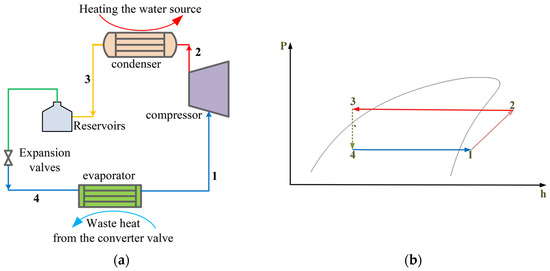
Figure 3.
BVCHPS: (a) System schematic; (b) P-H diagram. The numbers represent the entry and exit points of each component.
2.1.2. EEHPS
The schematic diagram and pressure enthalpy diagram of the EEHPS are shown in Figure 4. The ejector adopts a Lafarre nozzle [14,15,16], and its structure is shown in Figure 5.
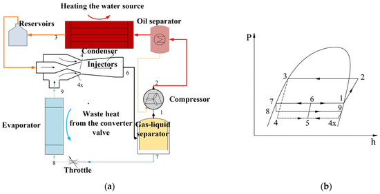
Figure 4.
Schematic and pressure enthalpy diagram of EEHPS: (a) System schematic; (b) P-H diagram. The numbers represent the entry and exit points of each component.

Figure 5.
Ejector nozzle structure diagram.
The principal difference between the two systems is that the one in question employs an ejector instead of an expansion valve. The working principle of the system is therefore characterized by high-speed and low-pressure fluid injection of gaseous refrigerant, which enters the system from another inlet of the ejector. In an ideal state, the gaseous refrigerant is injected into the state point 4x in an approximate isentropic expansion manner. The mixture is then mixed to the state point 5, expanded, and the speed reduced to increase the pressure to the state point 6. Finally, the gas–liquid separator is entered, where the gaseous and liquid refrigerants are separated. The gaseous component (the state point 1) enters the compressor, while the liquid component (the state point 7) is throttled and passed through the evaporator, forming a heat pump cycle [5].
2.2. Thermodynamic Modeling
2.2.1. COP
- BVCHPS
The thermodynamic performance calculation model of the BVCHPS, without considering resistance loss and heat leakage, is as follows.
- Condenser
- Evaporator
- Throttle valve
- Compressor
- The heating coefficient of the system
Among them, the specific enthalpy value of the working fluid at each state point is the following:
The specific entropy value of the working fluid at each state point is the following:
The specific exergy value of the working fluid at each state point’s unit mass flow rate is the following:
- 2.
- EEHPS
- Evaporator
- Throttle valve
The refrigerant undergoes enthalpy expansion in the throttle valve, during which it changes from a saturated liquid refrigerant to a gas–liquid two-phase refrigerant. During this process, the enthalpy of the refrigerant is equal and the pressure decreases.
- Compressor
- Gas–liquid separator
In the gas–liquid separator, the gas–liquid mixed refrigerant is separated, and the saturated liquid refrigerant flows into the evaporator, while the saturated gaseous refrigerant flows into the compressor.
- Condenser
- 3.
- Ejector
The ejector used in the EEHPS involves a two-phase flow and the process is complex. Therefore, in theoretical analysis, the following assumptions are made [15,16,17,18].
- (a)
- Except for the mixing chamber, the remaining parts of the ejector are in thermodynamic equilibrium, i.e., one-dimensional uniform flow, and the fluid at the nozzle throat reaches a clogged state;
- (b)
- Neglecting the influence of gravity on the fluid, ignoring the heat exchange between the fluid and the ejector wall, ignoring the kinetic energy of the fluid at the inlet of the ejector working nozzle and the inlet of the injection nozzle, and ignoring the kinetic energy of the fluid at the outlet of the ejector expansion chamber;
- (c)
- Adopting isentropic efficiency coefficients for the flow process of fluid in nozzles, suction chambers, and expansion chambers ηn, ηs, and ηD for correction;
- (d)
- Neglecting the pressure drop of fluids in evaporators, condensers, and connecting pipelines;
- (e)
- The system has no subcooling or overheating.
Based on the above assumptions, corresponding conservation control equations are established for each part of the ejector using the principles of mass conservation, momentum conservation, and energy conservation.
- Nozzle
The energy conservation law is used to analyze the flow velocity Vnt of the working fluid at the nozzle throat of the Lafarre nozzle from the inlet to the throat. The enthalpy value hni of the working fluid at the nozzle inlet and the actual enthalpy value hnt of the working fluid at the nozzle throat Vnt can be obtained.
In the Lafarre nozzle section of the ejector, the high-pressure liquid working fluid at the nozzle inlet depressurizes and accelerates, converting its pressure potential energy into kinetic energy, and the state changes from liquid fluid to gas–liquid two-phase fluid. The working fluid at the throat of the Lafarre nozzle is in a choked state, with a flow velocity reaching the speed of sound. The gradually expanding part of the nozzle behind the throat continues to accelerate to a supersonic state, attracting the ejected fluid. The sound velocity Vsound of the working fluid gas–liquid two-phase flow at the nozzle throat can be obtained from the sound velocity calculation model.
The density of the working fluid at the throat is the following:
The relationship between the mass flow rate mnt of the working fluid and the throat area Ant is
- Throat to the nozzle outlet
According to the law of conservation of mass, the mass flow rate of the working fluid passing through the nozzle throat is equal to the mass flow rate passing through the nozzle outlet.
The energy conservation law is used to analyze the flow velocity Vne of the working fluid at the nozzle throat from the nozzle throat to the outlet of the Lafarre nozzle. The enthalpy value hnt of the working fluid at the nozzle throat and the actual enthalpy value hne of the working fluid at the nozzle outlet can be obtained.
The density of the working fluid at the outlet is
The relationship between the mass flow rate of the working fluid and the outlet area is
Assuming the pressure Pne is iteratively calculated, relevant parameters such as pressure Pne and dryness Xne of the working fluid at the nozzle outlet state point are obtained.
- Ejector suction chamber
The energy conservation law is used to analyze the inlet to outlet of the ejected fluid. The flow velocity Vse of the ejected fluid can be obtained from the enthalpy value hsi of the inlet ejected fluid and the actual enthalpy value hse of the outlet ejected fluid.
Due to the use of equal area mixing in the ejector in this article, the outlet area Ase of the ejected fluid can be obtained from the mixing chamber area Am and the Lafarre nozzle outlet area Ane.
The density of the ejected fluid at the outlet is
The relationship between the mass flow rate of the ejected fluid and the outlet area is
Assuming the injection ratio of the ejector is , the mass flow rate of the injection fluid can be obtained as
- Ejector expansion mixing chamber
The working fluid in the mixing chamber follows the laws of mass conservation, momentum conservation, and energy conservation, and a theoretical model of the ejector mixing chamber can be obtained.
- Ejector expansion chamber
Using the law of conservation of energy for the inlet to the outlet section of the expansion chamber, based on the aforementioned assumptions, it can be inferred that
According to the law of conservation of mass, it is known that the mass of gas flowing toward the compressor in the gas–liquid separator is equal to the mass of the working fluid, and the mass of liquid flowing toward the evaporator in the gas–liquid separator is equal to the mass of the injected fluid.
Iteratively calculate the injection ratio μ of the ejector to obtain the injection ratio μ.
The iterative method employed for the JPHPS is summarized in Figure 6.
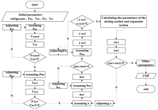
Figure 6.
Modeling of injection expansion heat pump system.
2.2.2. Exergy Efficiency
According to the law of thermodynamics [18], the value of exergy for stable logistics to change reversibly from any given state through an open system to an environmental state is the following:
The ratio of the exergy loss of each device to the system input is defined as the exergy loss coefficient:
The system exergy efficiency is the ratio of the effective exergy output of the system to the effective exergy input of the system:
2.3. Model Validation
The simulation results were validated against empirical data sourced from [19]. Table 1 shows the main parameters of Ref. [19] for simulation validation.

Table 1.
Model parameters used for simulation validation.
The verification results depicted in Figure 7 below demonstrate a favorable concordance with the literature data, exhibiting a maximum deviation of approximately 11% and an average deviation of around 9%.
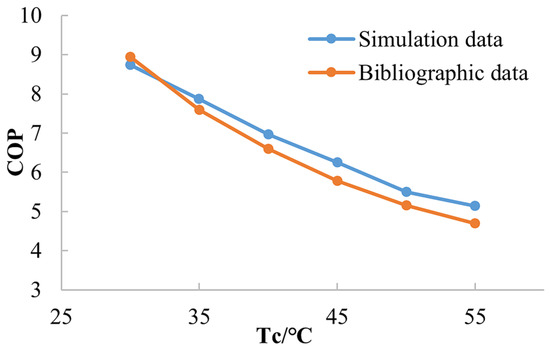
Figure 7.
Data verification.
3. Results
In this article, the physical property data in the two-phase flow sound velocity calculation model REFPROP10.0 can be iteratively calculated to obtain relevant parameters such as the pressure Pnt and dryness Xnt of the working fluid at the nozzle throat state point.
According to the cooling water monitoring data of the converter valve (Figure 1), the design temperatures of the condenser and evaporator are set at 90 ± 5 °C and 30 ± 5 °C, respectively.
3.1. COP Results
To further compare the thermal properties of heat pump systems using different refrigerants, this section analyzes and compares the performance of five refrigerants suitable for high-temperature water source heat pump systems in a single evaporator air source heat pump system with two-phase injection pressurization. The physical parameters of the refrigerants are shown in Table 2.

Table 2.
Comparison of the properties of the five refrigerants.
According to the analysis in the previous section, the optimal size of the ejector under theoretical conditions is 1.7 mm for the nozzle throat diameter, 2.8 mm for the nozzle outlet diameter, and 3.9 mm for the ejector mixing chamber diameter. We performed performance analysis on five refrigerants at this size.
Figure 8 shows the change of the COP with evaporation temperature at a condensing temperature of 80 °C for two heat pump systems using different refrigerants.
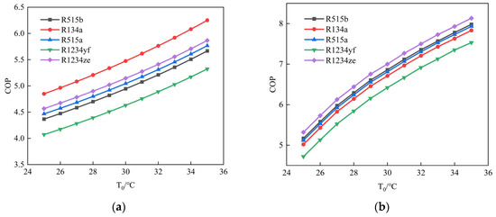
Figure 8.
Variation of the properties of the five refrigerants with evaporation temperature: (a) BVCHPS; (b) EEHPS.
As shown in Figure 8, when the condensation temperature remains unchanged, the COP of both systems increases with the increase in evaporation temperature. However, the increasing trend of COP in EEHPS is gradually slowing down. This may be due to the fact that the lower the evaporation temperature, the lower the pressure of the injected fluid in the injector, resulting in a greater throttle loss that the injector can recover and a greater trend in the COP variation.
3.2. Exergy Efficiency Results
This article sets Te to 30 °C and Tc to 85 °C. Table 3 lists the exergy loss and exergy loss coefficient of the EEHPS components. Figure 9 shows the efficiency comparison between the BVCHPS and EEHPS. The efficiency of the EEHPS is about 8% higher than that of the BVCHPS at various evaporating temperatures.

Table 3.
Exergy loss and exergy loss coefficient of EEHPS components.
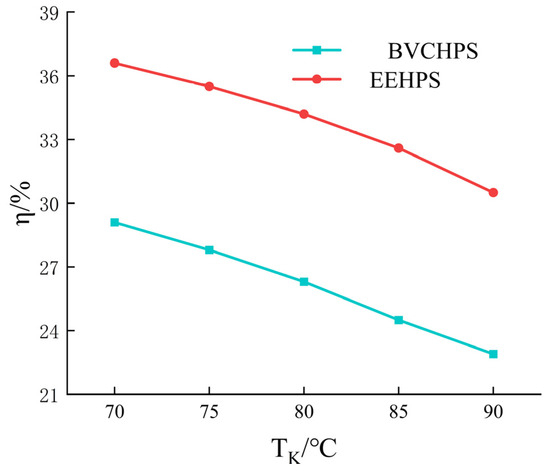
Figure 9.
Exergy efficiency comparison between two systems.
When the evaporation temperature is constant, as the condensation temperature increases, the compressor pressure ratio increases. The increased power required by the compressor leads to an increase in condensation temperature and a decrease in the exergy efficiency of both systems. However, the EEHPS injector effectively utilizes the pressure loss during the throttling process, resulting in its higher exergy efficiency over the BVCHPS.
3.3. Influence of Ejector Parameters on System Performance
- Design parameters
Considering the wider application of R134a, we performed system analysis using R134a as the refrigerant.
As a core component in the EEHPS, the size parameters of the ejector have a significant impact on the performance of the ejector itself and the overall system.
The theoretical optimized design parameters for the injector nozzle throat diameter Dnt, nozzle outlet diameter Dne, and mixing chamber diameter Dm are obtained through comparative analysis in the design stage.
- Comparison of nozzle structural parameters and their impact on system COP
According to the research of Liu [14] and Bilir [17], it is known that when the area of the nozzle throat decreases, the injection coefficient and system COP change accordingly. However, considering the process issues in actual production, a small throat diameter can lead to processing difficulties, and the processing smoothness does not meet the standard. A more reasonable value is needed.
The calculation analysis is shown in Figure 10, Figure 11 and Figure 12. With other parameters unchanged, the COP value of the two-phase flow jet heat pump system increases first and then decreases with the increase in throat diameter, mixing chamber diameter, and nozzle outlet diameter at different evaporation temperatures. There exists an optimal design point for the COP of the system under the set conditions.
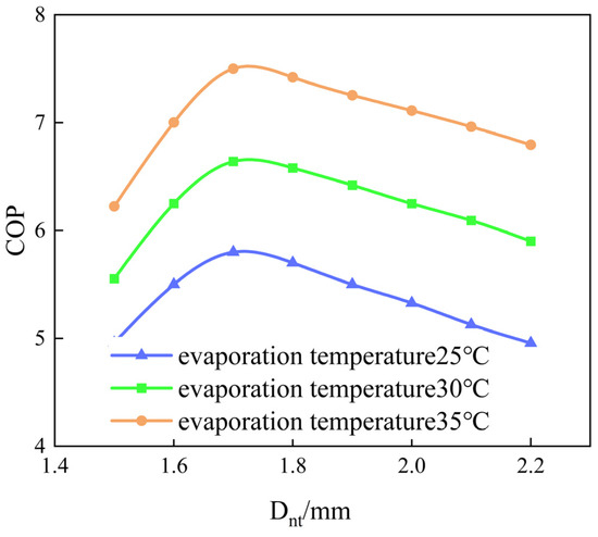
Figure 10.
Change of COP with nozzle throat diameter Dnt.
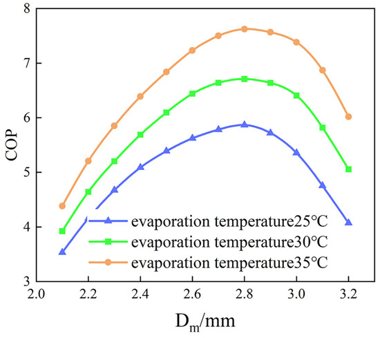
Figure 11.
Variation of COP with diameter Dm of mixing chamber at different evaporation temperatures.
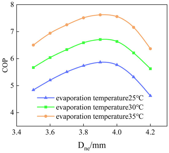
Figure 12.
Change of COP with nozzle outlet diameter Dne at different evaporation temperatures.
According to the internal flow mechanism of the injector, shock waves will be generated at the nozzle outlet or nozzle expansion section. The position and influence of the shock waves will vary with the cross-sectional area of the nozzle throat. Shock waves can cause sudden changes in velocity and pressure, resulting in the velocity stratification of the two fluids in the first half of the mixing chamber. The large velocity difference inside the fluid increases friction losses and reduces the performance of the injector.
If the cross-sectional area of the nozzle outlet is too large, the interior of the nozzle will expand excessively, generating shock waves in the nozzle expansion section and reducing the efficiency of the nozzle. On the contrary, if the cross-sectional area of the nozzle outlet is too small, the internal expansion of the nozzle is insufficient, and the fluid continues to expand after passing through the nozzle; the working jet cannot effectively suck in the injection jet, which will also cause energy loss and reduce the performance of the injector.
Excessive mixing chamber diameter can lead to uneven mixing. Besides, a small mixing chamber diameter reduces the fluid mass flow rate, resulting in the insufficient output power of the injector or the inability to meet design requirements. A small mixing chamber can also cause significant flow resistance, leading to increased energy consumption or increased pressure loss in the injector. Therefore, there exists an optimal design point for the structural parameters of the injector under design conditions theoretically. Figure 10, Figure 11 and Figure 12 show that the optimal Dnt, Dne, and Dm for the injector in the EEHPS are 1.7 mm, 2.8 mm, and 3.9 mm, respectively.
4. Conclusions
This article proposes a solution to improve the low-temperature waste heat utilization of UVDC converter valves by using heat pump technology to upgrade low-grade heat sources to high-grade heat sources. This enables high-grade waste heat to drive heating systems, refrigeration systems, seawater desalination, and sewage treatment in various fields. The main work carried out includes the following:
- (1)
- The average temperature range of available waste heat of a certain type of converter valve during a certain year is between 30 and 47 °C, and the capacity level is between 35,000 and 5500 kW; This low-grade high-capacity heat source is upgraded to a heat source of 70–90 °C through heat pump technology, which is applied in fields such as refrigeration, heating, seawater desalination technology, and sewage treatment.
- (2)
- Under the calculation conditions set in this article, thermal analysis was conducted on the BVCHPS and EEHPS. The results showed that selecting five refrigeration refrigerants (R515b, R515a, R134a, R1234yf, and R1234ze) for analysis showed that the EEHPS can effectively improve the system COP. In addition, the exergy efficiency analyzed with R515b as a representative can be improved by about 8%.
- (3)
- The analysis of the structural parameters of the ejector shows that the nozzle throat diameter, mixing chamber diameter, and nozzle outlet diameter of the ejector have an impact on the COP of the EEHPS, and there is an optimal diameter size available. Subsequent work will carry out optimization design and experimental testing.
- (4)
- The research group will further carry out the construction of the BVCHPS and EEHPS experimental platforms to verify the accuracy of the theoretical analysis results in this paper.
Author Contributions
Conceptualization, M.J. and X.Z.; methodology, X.Z. and J.Z.; validation, M.J., X.Z. and J.Z.; formal analysis, L.Z.; writing—original draft preparation, M.J. and X.Z.; writing—review and editing, X.Z.; supervision, J.Z.; project administration, L.Z. All authors have read and agreed to the published version of the manuscript.
Funding
This research was funded by the 2023 State Grid Corporation of China headquarters technology project (Key Technology Research on Green and Energy Saving Construction of Ultra High Voltage Converter Stations 5200-202356130A-1-1-ZN). The APC was funded by State Grid Economic and Technological Research Institute Co., Ltd.
Data Availability Statement
The raw data supporting the conclusions of this article will be made available by the authors on request.
Conflicts of Interest
Author Menghan Jin was employed by the State Grid Economic and Technological Research Institute Co., Ltd. Author Limin Zhang was employed by the State Grid Shandong Electric Power Company Construction Company. The remaining authors declare that the research was conducted in the absence of any commercial or financial relationships that could be construed as a potential conflict of interest.
References
- Zhou, J.H.; Zhang, X.J.; Hou, J.Y.; Wang, H.; Yang, H. A New Converter Valve Cooling System Based on Residual Heat Recovery. South. Power Syst. Technol. 2019, 13, 16–23. (In Chinese) [Google Scholar] [CrossRef]
- Yang, L.; Zhang, L.; Zhou, Y.B.; Hou, T.; Xu, S.K. Integrated Design Scheme of External Cooling System of VSC-HVDC Converter Valve and Water-Cooled Transformer. South. Power Syst. Technol. 2021, 15, 15–19. (In Chinese) [Google Scholar] [CrossRef]
- Kim, M.-H.; Pettersen, J.; Bullard, C.W. Fundamental process and system design issues in CO2 vapor compression systems. Prog. Energy Combust. Sci. 2004, 30, 119–174. [Google Scholar] [CrossRef]
- Elbel, S.; Lawrence, N. Review of recent developments in advanced ejector technology. Int. J. Refrig. 2016, 62, 1–18. [Google Scholar] [CrossRef]
- Harrell, G.S.; Kornhauser, A.A. Performance tests of a two-phase ejector. In Proceedings of the 30th Intersociety Energy Conversion Engineering Conference, Orlando, FL, USA, 30 July–4 August 1995; pp. 49–53. [Google Scholar]
- Zhang, Z.Y.; Feng, X.; Tian, D.Z.; Yang, J.; Chang, L. Progress in ejector-expansion vapor compression refrigeration and heat pump systems. Energy Convers. Manag. 2020, 207, 112529. [Google Scholar] [CrossRef]
- Chua, K.J.; Chou, S.K.; Yang, W.M. Advances in heat pump systems: A review. Appl. Energy 2010, 87, 3611–3624. [Google Scholar] [CrossRef]
- Gagan, J.; S’mierciew, K.; Butrymowicz, D. Performance of ejection refrigeration system operating with R-1234ze(E) driven by ultra-low grade heat source. Int. J. Refrig. 2018, 88, 458–471. [Google Scholar] [CrossRef]
- Li, S.Y.; Lu, J.; Li, W.Y.; Huang, S.; Tian, L. Comparative performance of ternary azeotropic mixtures as substitutes for R134a in dual-temperature air source heat pump combined ejector. Therm. Sci. Eng. Prog. 2023, 37, 101577. [Google Scholar] [CrossRef]
- Zou, L.G.; Liu, Y.; Yu, J.L. Energy, exergy and economic evaluation of a solar enhanced ejector expansion heat pump cycle. Renew. Energy 2023, 217, 119119. [Google Scholar] [CrossRef]
- Zhao, Y.; Yu, J.L. Thermodynamic analysis of a modified vapor-injection heat pump cycle using an ejector. Int. J. Refrig. 2023, 145, 137–147. [Google Scholar] [CrossRef]
- Al-Sayyab, A.K.S.; Navarro-Esbrí, J.; Mota-Babiloni, A. Energy, exergy, and environmental (3E) analysis of a compound ejector-heat pump with low GWP refrigerants for simultaneous data center cooling and district heating. Int. J. Refrig. 2022, 133, 61–72. [Google Scholar] [CrossRef]
- Wang, X.; Yu, J.L.; Xing, M.B. Performance analysis of a new ejector enhanced vapor injection heat pump cycle. Energy Convers. Manag. 2015, 100, 242–248. [Google Scholar] [CrossRef]
- Liu, F.; Groll, A.E. Study of ejector efficiencies in refrigeration cycles. Appl. Therm. Eng. 2013, 52, 360–370. [Google Scholar] [CrossRef]
- Li, H.S.; Cao, F.; Bu, X.B.; Wang, L.; Wang, X. Performance characteristics of R1234yf ejector-expansion refrigeration cycle. Appl. Energy 2014, 121, 96–103. [Google Scholar] [CrossRef]
- Mastrowski, M.; Smolka, J.; Butrymowicz, D.; Antczak, Ł.; Gagan, J.; Śmierciew, K. Experimental validation of the theoretical ejector model in a low-grade waste heat refrigeration system using R1233zdE as a working fluid. Appl. Therm. Eng. 2024, 236, 121716. [Google Scholar] [CrossRef]
- Bilir, S.N.; ERsoy, H.K. Experimental investigation on motive nozzle throat diameter for an ejector expansion refrigeration system. Energy Convers. Manag. 2016, 124, 1–12. [Google Scholar] [CrossRef]
- Dincer, I.; Rosen, M.A. Thermal Energy Storage: Systems and Applications; John Wiley & Sons: Hoboken, NJ, USA, 2010. [Google Scholar]
- Zhu, G.Q. A Study on the Performance of Air Source Heat Pump Based on Two-Phase Ejector Boosting Pressure. Master’s Thesis, Taiyuan University of Technology, Taiyuan, China, 2017. (In Chinese). [Google Scholar]
Disclaimer/Publisher’s Note: The statements, opinions and data contained in all publications are solely those of the individual author(s) and contributor(s) and not of MDPI and/or the editor(s). MDPI and/or the editor(s) disclaim responsibility for any injury to people or property resulting from any ideas, methods, instructions or products referred to in the content. |
© 2024 by the authors. Licensee MDPI, Basel, Switzerland. This article is an open access article distributed under the terms and conditions of the Creative Commons Attribution (CC BY) license (https://creativecommons.org/licenses/by/4.0/).