Abstract
With the widespread integration of distributed resources, optimizing the operation of urban distribution networks faces challenges including uneven source-load-storage distribution, fluctuating feeder power flows, load imbalances, and network congestion. The urban snow-shaped distribution network (SDN), characterized by numerous intra-station and inter-station tie switches, serves as a robust framework to intelligently address these issues. This study focuses on enhancing the safe and efficient operation of SDNs through a two-phase optimal scheduling model that coordinates source-network-load-storage. In the day-ahead scheduling phase, an optimization model is formulated to minimize operational costs and mitigate load imbalances. This model integrates network reconfiguration, energy storage systems (ESSs), and flexible load (FL). During intra-day scheduling, a rolling optimization model based on model predictive control adjusts operations using the day-ahead plan to minimize the costs and penalties associated with power adjustments. It provides precise control over ESS and FL outputs, promptly correcting deviations caused by prediction errors. Finally, the proposed model is verified by an actual example of a snow-shaped distribution network in Tianjin. The results indicate significant improvements in leveraging coordinated interactions among source-network-load-storage, effectively reducing spatial-temporal load imbalances within feeder clusters and minimizing the impact of prediction inaccuracies.
1. Introduction
With the extensive integration of distributed power sources, ESSs, and other new elements, the phenomena of “duck curve” and “canyon curve” of the net load have become more and more obvious, and the planning and operation of distribution systems are facing great challenges caused by the uncertainties of source-load strengths, drastic feeder fluctuations, and spatial-temporal imbalances of feeder loads. The urban snow-shaped distribution network (SDN) [1], with intra-station and inter-station tie switches, can realize a wide range of load transfer trends through network topology reconfiguration and, simultaneously, effectively alleviate the spatial-temporal imbalances of loads in feeder clusters and reduce the impact of prediction errors, providing an effective means for coordinating source-network-load-storage interactions.
Compared to the traditional 10 kV grid, the SDN is evolved and upgraded on the basis of a single- and double-ring distribution network, forming a feeder cluster through the addition of intra-station and inter-station tie switches. Currently, SDN grids have been put into practical operation in demonstration zones such as the National Games Village. The construction of SDNs is of great significance for promoting the high-quality development of China’s distribution network and creating a world-leading urban distribution network. The load transfer capability, reliability, and efficiency benefits of the snow-shaped distribution network structure, along with suitable application scenarios, have been discussed in detail in [1]. Based on the advantages of SDNs to withstand the uncertainties of new energy sources and to adapt to the high proportion of diversified sources, such as new energy sources, energy storage, and electric vehicles, it is essential to conduct research on the optimization and scheduling of SDNs.
So far, many studies have carried out research on how to deal with coordinated modern optimization and energy management in distribution networks. A traditional distribution network is a single radial network, and its operation optimization is relatively easy. The scheduling object is relatively single, limited to a limited number of power supplies, substations, distribution equipment, and switches, and the regulating measures are mainly for network reconfiguration and reactive power voltage optimization control [2,3,4,5]. With access to various flexible resources, the operation and scheduling of modern urban active distribution grids (active distribution grids, integrated energy systems) need to face more complex and diverse scheduling objects [6,7]. Flexible regulation of ESSs and FL can improve power consumption behavior, achieve peak shaving and valley filling, and alleviate load imbalance problems [8,9,10,11,12]. A useful approach for site selection of shared energy storage is proposed for improving the utilization rate and profitability of ESSs [13]. The coordinated charging practices of EVs, as flexible loads, can be used to handle fluctuating renewable energy outputs and achieve optimal voltage stability and significant cost savings [14]. With dynamic reconfiguration [15,16,17], load balancing is achieved by changing the topology to transfer the load from highly loaded feeders to less loaded feeders. Based on an improved binary particle swarm optimization algorithm, a reconfiguration method for distribution networks with the objective of load balancing is proposed [18]. A multi-objective dynamic reconfiguration optimization model suitable for multi-level switching modes is formulated to minimize operation costs, load imbalances, and PV curtailment [19]. To solve this optimization problem more quickly and accurately, scholars have put forward a variety of solving algorithms, including mathematical optimization methods [20,21] and heuristic algorithms [22]. The linear programming method can simplify the constraints of the model and has the advantages of fast calculation speed and good convergence. The convex relaxation technique represented by second-order cone programming (SOCP) is used more and more frequently, as it can obtain the globally optimal solution and reduce the computation time. Previous studies have investigated the above measures accordingly, but most of them focused on the traditional distribution network represented by one feeder (e.g., IEEE33) or an ADN with control of distributed energy resources. With the extensive integration of distributed resources (DRs) into distribution networks, the optimization problem of distribution networks needs the joint operation optimization of multiple coordinated feeders and stations rather than the operation optimization of a single feeder.
The increasing penetration of fluctuating renewable energy generation and fine-grained controllability of loads have redirected attention to online optimization methods on different time scales [23]. The penetration of distributed power sources and diversified loads has led to increased uncertainty in forecasting, with deviations between intra-day operating conditions and day-ahead forecasts. In order to correct the scheduling deviation caused by prediction deviations in a timely manner, the stochastic programming (SP) method, which is an effective uncertainty-tackling approach, can be applied. Diverse uncertainties from loads and renewable energy generation are handled by scenario-based multi-stage SP methods, which coordinate the day-ahead timescale and intra-day timescale [24,25,26,27]. Although the rolling optimization method can be adopted for the above method, it cannot fully meet the needs of online optimization adjustment in actual operation. The model predictive control (MPC) method, based on the idea of rolling optimization and feedback correction, can better adapt to the problem of uncertain predictions and has good robustness. MPC is widely used as a closed-loop optimization control means in the intra-day optimization operation phase [28,29,30,31,32,33,34]. Supply–demand balance can be met in the microgrid under complex uncertainties using MPC, and the output randomness of the exchanged power with the utility grid of the microgrid can be reduced [28,29,30]. MPC-based methods can coordinately utilize different controllable resources (e.g., ESSs, distributed generators) to effectively enhance the safety and economy of active distribution networks (ADNs) at multi-timescales, maximize accommodate renewable energy resources, and deal with multiple uncertainties [31,32,33,34].
To the best of our knowledge, this is the first study on the two-stage optimal scheduling problem of urban SDNs. Relative to the previous grid structure, the SDN is upgraded based on a group of 10 kV single- ring or double-ring networks by adding new station tie switches, forming a ring mesh feeder cluster with eight or six lines. By enabling multi-connection of the feeders, the SDN can comprehensively take into account the dynamic reconfiguration, ESSs, and FL flexible adjustment to achieve a wide range of collaborative optimization operations. Therefore, it is of great significance to consider the synergistic source-network-load-storage interactions in SDNs to realize load balancing within feeder clusters to enhance system operation economy and security.
Based on the studies mentioned above, considering feeder load balancing and uncertainty, a two-phase optimal method based on the coordination of source-network-load-storage is proposed in this paper for day-ahead and intra-day operation of SDNs [35].
- (1)
- In the day-ahead stage, the model is developed to minimize operation costs and load imbalances, which takes into account network reconfiguration, energy storage, and flexible load. The optimization runs at 1 h intervals to obtain dynamic reconfiguration schemes and economic scheduling.
- (2)
- In the intra-day phase, the optimal interval is 15 min, and the rolling optimization correction is carried out to minimize operational costs and power adjustment penalty costs, improving the accuracy of scheduling and finely regulating and controlling the output of ESSs and FL.
- (3)
- The results confirm that the proposed method maximizes the advantages of load transfer and source-network-load-storage coordination potential in SDNs. And it fully utilizes the synergistic flexible regulating characteristics of ESSs and FL, which effectively cope with the uncertainties of source and load.
The remainder of this paper is organized as follows. Section 2 describes the snow-shaped distribution network structure. Section 3 introduces the two-phase optimal scheduling framework based on coordination of source-network-load-storage in urban SDNs. Section 4 describes the day-ahead optimal scheduling model. Section 5 describes the intra-day rolling optimal scheduling model based on model predictive control. By applying convex relaxation, the original problem is converted into an SOCP model in Section 6. Case studies are given in Section 7 to verify the effectiveness of the proposed method using the three-station, six-wire, snow-shaped distribution system. Section 8 concludes the paper.
2. Snow-Shaped Distribution Network
The snow-shaped distribution network is a meshed ring structure based on the traditional cable single- and double-ring network structure, which is derived and upgraded into a ring network box as a networking unit. It consists of eight 10 kV lines from four substations or six 10 kV lines from three substations according to the regular connection. In each substation, there are two 10 kV outgoing lines, each with an inter-station tie switch and an intra-station tie switch.
According to the number of substations, the snow-shaped distribution network can be categorized into three-station mode and four-station mode. Taking the three-station mode as an example, as shown in Figure 1, on the basis of the existing three groups of the single-ring network, three new intra-station tie switches are added to form a snow-shaped distribution network feeder group.
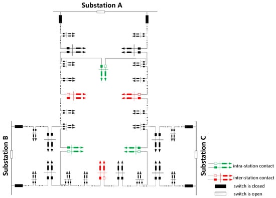
Figure 1.
Schematic of a three-station six-feeder snow-shaped distribution network.
The topology of the snow-shaped distribution network has the natural characteristics of both rotational symmetry and bilateral symmetry. And the ring grid structure is flexible and reliable, which provides a physical grid foundation for the coordinated regulation and optimization of various controllable resources, such as distributed power sources, electric vehicles, and energy storage within the feeder clusters, and it supports source-grid-load-storage interactions and convergence in the new type power systems.
3. Two-Stage Optimal Scheduling Framework
In order to realize the safe and efficient operation of the snow-shaped distribution network, this paper proposes a two-stage optimization method based on source-network-load-storage multi-factor co-regulation of the snow-shaped distribution network in the day-ahead stage and intra-day stage. The framework is shown in Figure 2, which consists of day-ahead optimal scheduling and intra-day rolling optimization.
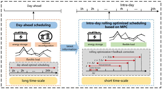
Figure 2.
Multi-stage scheduling framework based on MPC.
- (1)
- Day-ahead optimal scheduling
According to the forecast of distributed renewable energy, load demand, and market electricity price information, a day-ahead optimal model of the SDN is established with the comprehensive objectives of system operation economics and load balance, considering the constraints of system security operation, network reconfiguration, energy storage, and so on. Using second-order cone relaxation and linearization techniques, the original model is transformed into a mixed-integer second-order cone planning model. Then, the model is solved to obtain the opening and closing states of sectional contact switches, as well as the day-ahead scheduling strategy for the energy storage and flexible load, realizing the flexible temporal and spatial transfer of load in the feeder clusters.
- (2)
- Intra-day rolling optimization based on model predictive control
With the penetration of new energy sources, increasing uncertainty causes the distributed power output and load to deviate from the forecast, and the day-ahead scheduling plan often fails to meet the power balance demand. Therefore, MPC-based rolling optimization is performed in the intra-day phase to correct the day-ahead schedule. Model predictive control, as an optimization control method for investigating uncertain systems, consists of three components: prediction model, rolling optimization, and feedback correction. Based on the latest information, ultra-short-term forecasts of renewable energy output and load information for future MΔt′ time periods are made. The optimization time interval is reduced from 1 h in the day-ahead phase to Δt′, with the objective of minimizing the operating cost and the deviation of the adjusted output from day-ahead scheduling. The rolling optimization is carried out to obtain the output information to correct the forecast information in the next optimization, which is continuously updated as the time window advances, repeating the above process to perform a new round of optimization. This process constitutes a closed-loop optimization, which corrects the scheduling result deviation caused by prediction error in a timely manner and improves the optimization scheduling accuracy.
4. Day-Ahead Optimal Scheduling Model
4.1. Objective Function
The time interval of the day-ahead optimal scheduling stage a few days ago is 1 h. Considering the dimensionality difference in the magnitude of the two sub-objectives of economic cost and load balancing, it is necessary to normalize the sub-objectives and weight them as a comprehensive objective function. The specific expression is shown in Equation (1):
where FDA represents the total objective function; Fenc represents the total economic operation cost; Fbal represents the load balance degree; and are the initial system operating cost and load balancing degree, respectively; and ω1 and ω2 indicate the weight of each sub-objective.
The operation economic cost includes the cost of purchasing electricity, energy storage charging and discharging scheduling, flexible load scheduling, and switch action. In this paper, the energy storage in the model is owned by the power company belonging to the distribution network, the distribution network can be directly regulated and controlled, and the flexible load is mainly considered to be curtailable load. The economic objective function is expressed as follows:
where CEXT, CESS, and CDR represent the cost of purchasing electricity, energy storage dispatching, and flexible load dispatching, respectively. CNR represents the switch action cost in the dynamic reconfiguration. ψEXT, ψESS, and ψDR represent the node sets of the loop network connected with the upper substation, energy storage, and flexible load, respectively. ψNR represents the set of branches that can participate in dynamic reconfiguration. λ(t) represents electricity price at time t. PEXT,i(t) represents the purchased electric power at moment t in ring node i. Δt represents the time step, which is 1 h. λESS represents the operating cost per unit of electricity for energy storage. PESS,ch,i(t) and PESS,dis,i(t) represent the charging and discharging power of energy storage in the day-ahead phase, respectively. λDR represents the reimbursement cost per unit of electricity for the curtailable load. PDR,i(t) represents the amount of load reduction at time t in ring node i. BNR represents the number of switching operations. λNR represents the cost of the switching operations. T is the total period of the time horizon, which is 24 h.
The network reconfiguration load balancing objective function is expressed as follows:
where Sij (t) is the apparent power of branch ij at moment t; Sij,max is the maximum apparent power of branch ij; Pij(t) and Qij(t) denote the active and reactive power flowing from ring node i to ring node j at moment t, respectively; and Ωl is the set of all branches in the SDN.
4.2. Constraints
- (1)
- Power flow constraints
Considering the reconfiguration characteristics of the snow-shaped distribution network, 0–1 variable aij(t) is introduced to represent the switch casting state on branch ij based on the traditional Distflow current model (aij(t) = 0 means that the switches on branch ij are open), as follows:
where Ωin,j and Ωout,j denote the sets of ring nodes in the SDN with node j as the end ring node and the first ring node, respectively; Uj(t) denotes the voltage magnitude at ring node j at moment t; Pj(t) and Qj(t) denote the active and reactive power injected at ring node j at moment t, respectively; Rij and Xij denote the resistance and reactance magnitude of branch ij, respectively; and Iij(t) denotes the current magnitude of branch ij at moment t.
- (2)
- Power balance constraints
- (3)
- Node voltage limit constraints
- (4)
- Current constraints
- (5)
- Dynamic reconfiguration constraints
- (6)
- Switching action count constraints
- (7)
- Energy storage constraints
Equation (20) is the relationship between stored energy and the charging/discharging power of energy storage at time t. SESS,i(t) is the energy of energy storage at time t in ring node i. ηch and ηdis are the charging efficiency and discharging efficiency, respectively. Equation (21) is the capacity constraints of energy storage. CESS,max and CESS,min are the maximum and minimum state of charge, respectively. EESS,i is the rated capacity of energy storage in ring node i. Equation (22) is the discharging power and charging power constraints. PESS,i is the rated power of energy storage at ring node i. μdis(t) and μch(t) are the discharging and charging state in ring node i at time t, respectively. Equation (23) is the working state constraints. The three states are idle, charging, and discharging, and it can only be in one state in any moment. Equation (24) is the dispatch periodic constraints. Equations (25) and (26) are the charging and discharging times constraints, respectively. NESS(t) is a 0–1 variable that indicates the moment of the energy storage charge/discharge state change. is the limited charging times of energy storage in a day.
- (8)
- Flexible load constraints
In this paper, flexible loads are mainly considered as curtailable loads.
where ΔPcut,i,min(t) and ΔPcut,i,max(t) are the lower and upper limits of the curtailable load in ring node i at time t, respectively; ΔPcut,min and ΔPcut,max are the lower and upper limits of curtailable load in a dispatch cycle, respectively; and μcut,i(t) is the curtailment state of curtailable load at ring node i at time t.
5. Intra-Day Rolling Optimal Scheduling Model
The snow-shaped distribution network’s topology and energy storage charging and discharging status are pre-determined for the day-ahead optimal scheduling. During the intra-day rolling optimization phase, the future state of the system is predicted online in real time using an ultra-short-term prediction method, which provides the basis for subsequent rolling optimization and feedback correction.
5.1. The Rolling Optimization Model
Based on the prediction model, with a time interval of 15 min, the objective function of the rolling optimal model is to minimize the system operating cost as well as the deviation of the adjusted output from the day-ahead scheduling. The switching action state and storage charging/discharging state obtained in the day-ahead stage are substituted into the intra-day model as fixed values. The model is solved to obtain the feeder outlet power, storage charge/discharge power, and flexible load dispatch power adjustment for the next hour. The objective function is expressed as follows:
- (1)
- Costs of purchasing electricity
- (2)
- Energy storage dispatch operating costs
- (3)
- Flexible load dispatch operating costs
- (4)
- Penalty costs for the deviations from day-ahead scheduling values
μ is a vector of the penalty coefficients for intra-day optimal power adjustment. μEXT, μESS, and μDR represent the penalty coefficients for feeder export power, energy storage charging and discharging power, and flexible load dispatch power adjustment, respectively. P0(t′ + mΔt′ − Δt′) is the initial value vector of the feeder export power, the storage charging and discharging power, and the flexible load regulation power in the SDN at moment t′ + mΔt′ − Δt′. ΔP(t′ + mΔt′) is the power adjustment vector at moment t′ + mΔt′ in the intra-day rolling optimization, where Δt′ represents the time interval, which is taken as 15 min, and M is taken as 4.
The relevant constraints include power flow constraints, node voltage limit constraints, current constraints, etc., which are similar to the constraints of the day-ahead optimal scheduling model. The network topology as well as the charging and discharging states of the energy storage have been determined in the day-ahead phase and are not optimized in the intra-day phase.
The power adjustment ΔP(t′ + mΔt′) for future mΔt′ moments can be obtained at moment t′, and the set of power adjustment during the MΔt′ time period is shown in Equation (37):
5.2. Feedback Correction Process
By executing the control commands of the first time period in each optimization process, the feeder export power, the storage charging and discharging power, and the flexible load dispatch power at moment t′ + Δt′ can be obtained, as follows:
At moment t′ + Δt′, the actual PV and load short-time forecasts of the system are updated, and the feeder export power, the storage charging and discharging power, and the flexible load regulation power of the snow-shaped distribution network at this time are used as the initial values for the next rolling optimization at moment t′ + Δt′, so as to form the closed-loop optimization expressed as follows:
where P0(t ′+ Δt′) is the initial power vector for the next round of rolling optimization at moment t′ + Δt′; and Preal(t′ + Δt′) is the actual output power vector at moment t′ + Δt′ after rolling optimization at moment t′.
6. Solution Methodology
The day-ahead optimal scheduling model of the snow-shaped distribution network contains nonlinear tidal power flow constraints, which belongs to the large-scale mixed-integer nonlinear programming (MINLP) problem. And the network topology constraints further increase the difficulty of model solution. In this paper, the original model can be converted to a mixed-integer second-order cone programming (MISOCP) model using cone relaxation, the Big M method, and piecewise linearization, which can be tractably solved by commercial solvers. The specific transformation process is as follows.
First, linearization of the objective function in Equation (7) is achieved by introducing auxiliary variable fij(t). The variable substitution formula is shown in Equation (40), and Equation (7) is converted to Equation (41):
Further, second-order cone transformations are realized by the Big M method as well as the variable transformation by introducing auxiliary variables iij(t) and ui(t). Constraint Equations (8)–(10) and (12)–(13) have the square representation of the voltage magnitude and current amplitude. We used variable substitution to realize the linearization, i.e., let ui(t) and iij(t) denote the quadratic terms, and the variable substitution formulas are shown in Equations (42) and (43):
The constraint Equations (8)–(10), (12) and (13) change accordingly to the linearized constraint Equations (44)–(46), (48) and (49):
We used 0–1 variable aij(t) to represent the switch states, i.e., power flow Equations (44) and (46). The 0–1 variable aij(t) = 0 means that the switches on branch ij are open. The active power and reactive power of the disconnected branch are zero. Constraint Equation (9) is merely applicable to the closed branch (i.e., aij(t) = 1) and cannot be directly solved by the optimization solver. By introducing the 0–1 variable aij(t), the Big M method is employed to relax Equation (9) and convert it into Equation (46). The application scope of Equation (46) is expanded to the entire distribution system branch set instead of being limited to just closed branches.
The power flow Equation (47) can be further relaxed to the following second-order cone constraint Equation (50):
Similarly, Equation (40) can be further transformed into the standard second-order cone form, as shown in Equation (51):
By introducing 0–1 variable bij(t), Equations (18) and (19) containing absolute values can be transformed into linear forms, as shown in Equations (52)–(54):
After the above transformation, the nonlinear constraints can be transformed into linearized constraints and second-order cone constraints. The day-ahead optimal scheduling model can be converted to a mixed-integer second-order cone programming (MISOCP) model, as shown in the equations below.
Equation (55) is the objective function that includes multi-objectives for economy and safety, where x is continuous optimization variables, and y is discrete 0–1 optimization variables. Equation (56) gives the equational constraints. Equation (57) gives the inequality constraints. Equation (58) gives the second-order cone constraints. After the transformation, the model can be tractably solved using established commercial solvers.
In the MPC-based intra-day stage, the intra-day rolling optimization scheduling model of the snow-shaped distribution network also contains nonlinear constraints, so it can also be solved using cone relaxation, the Big M method, and piecewise linearization. And since the reconfiguration scheme has been determined in the day-ahead phase, the intra-day model does not contain network dynamic reconfiguration constraints, so the transformation method is similar to the day-ahead stage, which will not be repeated here.
The overall solution methodology process is shown in Figure 3.
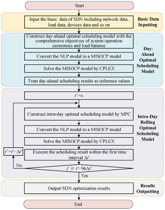
Figure 3.
Flowchart of the overall solution methodology process.
7. Case Study
7.1. Case Introduction
The network structure of this example system is depicted in Figure 4, where the green color represents intra-station tie switches, and the red color represents inter-station tie switches. The system includes 3 substations, 6 feeders, and 41 ring cages, with the rated voltage of 10 kV. Ring nodes 15, 18, 29, 32, 35, and 43 are connected to PV, and ring nodes 8, 17, 36, and 40 are connected to energy storage. Feeders F1 and F5 serve office loads, while feeders F2, F3, F4, and F6 serve residential loads. The typical load and solar profiles are depicted in Figure 5. The time-of-use tariff is illustrated in Figure 6. The cost of energy storage dispatch is 0.05 CNY/kW·h [18], the cost of flexible load unit power compensation is 0.06 CNY/kW·h [19], and the cost of switching actions is 200 CNY per operation [19].
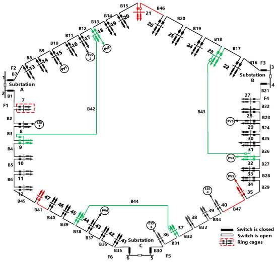
Figure 4.
Three-station six-feeder snow-shaped network.
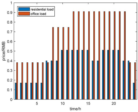
Figure 5.
The time-of-use tariff.
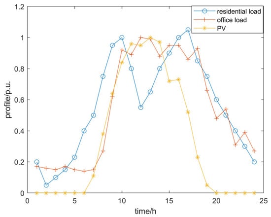
Figure 6.
Typical load and solar profiles.
The model is constructed in the MATLAB R2020a environment using the YALMIP toolkit and solved by the CPLEX solver. This paper presents five different optimization cases for comparative analysis.
Case 1: The system remains in its initial state, with no consideration of load transfer through dynamic reconfiguration, absence of energy storage, or flexible load involvement.
Case 2: The system considers the involvement of energy storage and flexible load, without dynamic reconfiguration.
Case 3: The system considers load transfer through dynamic reconfiguration, without involving energy storage and flexible load.
Case 4: The system considers load transfer through dynamic reconfiguration, with energy storage and flexible load participation.
Case 5: Intra-day rolling optimized dispatch based on model predictive control is considered on the basis of case 4.
7.2. Result Analysis
7.2.1. Day-Ahead Optimal Scheduling Results
The switch reconfiguration schemes under different cases are shown in Table 1.

Table 1.
Switch reconfiguration schemes.
Case 1 and case 2 remain in the initial state with switches disconnected on branches B42-43-44-45-46-47. Case 3, through dynamic reconfiguration of contact switches and sectionalized switches, enables flexible power load transfer to achieve load balancing. During 9:00~16:00, the switches on branches B4-B26-B33 are opened and the switches on branches B43-B45-B47 are closed. To address the heavy load on feeder F1, the switch on branch B4 is opened, the switch on branch B45 is closed, and the loads of ring nodes 10, 11, and 12 on feeder F1 are transferred to feeder F6 through the inter-station tie switch. To address the heavy load on feeder F5, and considering that the load ratio of feeder F4 is also high, supply transfer through the cross line is explored. By opening the switch on branch 26 and closing the switch on branch 43, the loads of ring nodes 32, 33, 34, and 35 on feeder F4 will be transferred to feeder F3 via intra-station tie switch. Also, by opening the switch on branch B33 and closing the switch on branch B47, the loads of ring nodes 39 and 40 on feeder F5 will be transferred to feeder F3 via feeder F4. During 17:00~19:00, the switch on branch B5 is opened, the switch on branch B4 is closed, and the loads of ring nodes 11 and 12 on feeder F1 are transferred to feeder F6. In case 4, energy storage and flexible loads are considered to participate in regulation to “cut peaks and fill valleys” of loads. This transfers power across time and coordinates the imbalance between “sources and loads,” ultimately reducing the number of dynamic reconfiguration switch actions compared to case 3.
Figure 7 shows the load conditions for each feeder in various cases. In case 1, during 8:00 to 19:00, the load ratios of feeders F1 and F5 exceed the feeder load threshold, peaking at 84% and 81% at 12:00, respectively. In case 2, the energy storage connected to feeders F1, F2, and F5 perform peak shaving and valley filling by charging and discharging, which helps to reduce feeder load fluctuations to some extent. However, due to the limited capacity of energy storage, its regulation ability is constrained. As a result, feeders F1 and F5 still experience relatively high loads between 10:00 and 18:00, reaching 67% and 60%, respectively. In case 3, while the heavy load issue is partially relieved by transferring the load from the heavily loaded feeder through dynamic reconfiguration, the loads on feeders F2 and F3 still exceed the load threshold from 9:00 to 10:00 and from 16:00 to 19:00. In case 4, with dynamic reconfiguration and the synergistic effect of energy storage and flexible load, the system achieves improved load balance and the load ratios of all feeders remain below the load threshold. This demonstrates that the synergistic optimization effectively addresses load imbalances and enables both economic and safe operation.
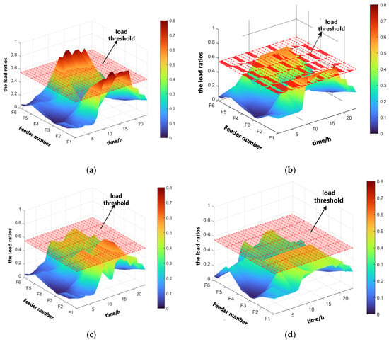
Figure 7.
Load conditions for each feeder in various cases. (a) Case 1; (b) case 2; (c) case 3; (d) case 4.
Figure 8 displays the energy storage output plan in case 4. Energy storage devices exhibit the operation characteristics of charging first and then discharging, but the specific charging and discharging powers and times are different. Taking ESS1 of ring cage 8 on feeder F1 as an example, ESS1 is charged from 1:00 to 7:00 during the low-price period and discharged from 10:00 to 18:00 during the high-price period, which reduces the purchased power of feeder F1 during the high-load period. Overall, the energy storage device charges at low-price and low-load hours, while it discharges at high-price and high-load hours. This ensures a balanced daily state of charge (SOC) for the energy storage devices. It also helps in smoothing the temporal and spatial load distribution differences, reducing power fluctuations and enhancing the security and economy of the system. Figure 9 shows the dispatch of FL and the overall load curve in case 4. This study primarily focuses on reducible loads, which are decreased not only during peak load periods but also during high-electricity-price periods. During low-electricity-price and low-load periods (1:00−7:00 and 22:00−24:00), reducible loads do not participate in reduction.”
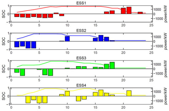
Figure 8.
Energy storage output plan in case 4.
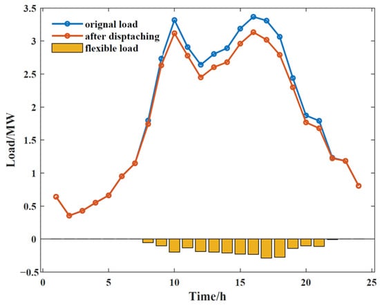
Figure 9.
Overall load profile in case 4.
Table 2 shows an economic comparison of three cases. Compared to case 1, the total costs in cases 2, 3, and 4 are reduced, indicating an improvement in system economics. In case 2, employing energy storage with the ‘energy consumption shifing from higher to lower prices’ strategy under the time-of-use pricing mechanism reduces the system’s electricity purchase costs. In case 3, dynamic reconfiguration is employed to balance loads, reduce network losses, and transfer some commercial loads from high-price areas to low-price residential areas via tie switches, thereby lowering the total cost. In case 4, the combined consideration of dynamic reconfiguration, energy storage, and flexible load optimal scheduling further reduces electricity purchase costs, decreasing the total cost from 259,086.65 CNY to 218,607.27 CNY, a reduction of approximately 15.62%, achieving economical system operation. Additionally, compared to case 3, the cost of switch operations is reduced, indicating that the coordinated consideration of energy storage and flexible load scheduling results in fewer switch operations, thus avoiding frequent switching actions.

Table 2.
Economic comparison.
7.2.2. Intra-Day Rolling Optimal Scheduling Results
Intra-day optimization uses a rolling optimization correction strategy based on MPC, with the day-ahead scheduling in case 3 as a reference. And the rolling optimization scheduling execution period is 15 min, with a total of 96 rolls. It is assumed that the intra-day data of light intensity and load information are simulated by the day-ahead power prediction superimposed on the normally distributed prediction error (light and load error expectation of 0, mean squared errors of 8% and 5%, respectively). The results of the day-ahead and intra-day forecasts for partial loads and PV are given in Figure 10. In this paper, we focus on the effectiveness of scheduling strategies, so we do not discuss the prediction methods in detail.
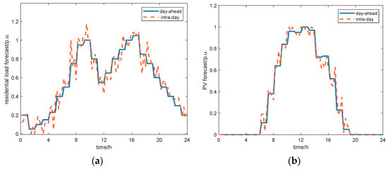
Figure 10.
Forecasting results of load and PV. (a) Load, (b) PV.
Figure 11 shows the comparison of energy storage and flexible load scheduling between case 3 and case 4. In case 3, the day-ahead plan takes an hour as the time scale, and the system cannot respond to renewable energy and load fluctuations in a timely manner. In case 4, intra-day MPC-based rolling optimization continuously employs real-time system measurements for feedback correction, resulting in more accurate intra-day scheduling compared to day-ahead scheduling. This enables fine control and management of energy storage and flexible load, and effectively protects against the adverse effects of uncertainty. The intra-day stage optimization has a time interval of 15 min, with each optimization cycle lasting 1 h, and the rolling optimization is performed 96 times. Statistics on the computation time for each rolling optimization reveal that the single optimization computation time for MPC-based intra-day rolling optimization scheduling is only about 0.19 s. This fully meets the requirements for online application and demonstrates the effectiveness of the coordinated optimization scheduling scheme proposed in this paper.
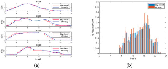
Figure 11.
Comparison of energy storage and flexible load scheduling. (a) Energy storage; (b) flexible load.
The scheduling accuracy is compared by analyzing the feeder output power in Figure 12. Without intra-day rolling optimization, the feeder outlet power experiences significant fluctuations around the planned values, making it difficult to achieve smooth and reliable operation of the distribution network. Implementing MPC-based rolling optimization scheduling reduces the deviations of feeder export power from the day-ahead stage, enhancing its capability to address the volatility and uncertainty of distributed power sources.

Figure 12.
Comparison of feeder outlet power. (a) F1, (b) F2, (c) F5.
The smoothing index p is defined in [36]. A smaller value of the smoothing coefficient p indicates a more effective smoothing out of fluctuations in the feeder export power. A comparison of smoothing coefficient indicators in feeders is shown in Table 3. The results demonstrate that rolling optimization using MPC during intra-day periods effectively reduces the smoothing coefficient indices of feeder F1, F2, and F5 export power, ensuring accurate tracking of the day-ahead planned values.

Table 3.
Comparison of smoothing coefficient indicators.
To assess how effectively MPC-based rolling optimization minimizes operating costs, we included an additional set of economic comparisons considering non-MPC and MPC.
From Table 4, it can be seen that the operating cost increases only by 746.31 CNY, about 0.34%, when MPC-based intra-day rolling optimization is considered. The slight increase in overall costs is mainly due to the rising scheduling costs of energy storage and flexible loads. Overall, the two-phase scheduling approach used in this paper achieves smooth and controllable scheduling of power on the contact line at a small cost penalty.

Table 4.
Comparison of the results considering non-MPC and MPC.
8. Conclusions
With increasing renewable energy resources and unbalanced load diffusion, how to deal with the resulting uncertainty and volatility has been a great challenge to distribution networks. In this paper, for the snow-shaped distribution network structure, based on model predictive control, a multi-stage optimal scheduling model of load transfer, energy storage equipment, and flexible load co-regulation is proposed to ensure the safe and economic operation of the system. The following conclusions are drawn:
- (1)
- During the day-ahead optimal scheduling stage, dynamic reconfiguration is employed to alter the status of contact switches and sectional switches for load transfer. This improves system load balance, taps into the snow-shaped distribution network’s power supply potential, and enhances system stability. Simultaneously, energy storage and flexible loads are considered to cooperate with power, avoiding frequent switch operations.
- (2)
- The intra-day rolling optimization stage is based on MPC to adjust the day-ahead optimal scheduling, regulate energy storage and flexible load output in a more refined way, and accurately track the planned feeder power output from the day-ahead stage. This helps to effectively address the uncertainties in new energy and load variations, ensuring the scheduling plan’s reasonableness.
- (3)
- The snow-shaped distribution network structure proposed in this paper is flexible and reliable. Taking advantage of intra-station and inter-station connections, it enables extensive load transfer, bolsters the precision of urban distribution network operations, and accommodates the high penetration of distributed power sources, flexible loads, energy storage, and other new elements for versatile integration.
Future research could consider the use of soft open points (SOPs) as a replacement for traditional inter-station and intra-station connections within snow-shaped distribution networks. This approach would enable flexible adjustment of network power flows, thereby enhancing the flow control capability of the snow-shaped distribution network. Such advancements would improve the network’s ability to adapt to fluctuations in distributed power source and load.
Author Contributions
Conceptualization, Z.W. and J.D.; methodology, Z.W. and J.D.; software, X.W.; validation, F.L.; formal analysis, Z.W.; investigation, J.D.; resources, Z.W., J.D., F.L. and X.W.; data curation, X.W.; writing—original draft preparation, X.W.; writing—review and editing, F.L. All authors have read and agreed to the published version of the manuscript.
Funding
This research was funded by Science and Technology Projects of State Grid Tianjin Electric Power Company (No. SGTJCN00FZJS2300841).
Data Availability Statement
Data are contained within the article.
Acknowledgments
The authors would also like to thank the anonymous reviewers for their valuable comments and suggestions to improve the quality of the paper.
Conflicts of Interest
Authors Zhe Wang and Jiali Duan were employed by the company State Grid Tianjin Electric Power Company. The authors declare that the research was conducted in the absence of any commercial or financial relationships that could be construed as a potential conflict of interest.
Abbreviations
| Abbreviations | ||
| SDN | snow-shaped distribution network | |
| ESS | energy storage system | |
| FL | flexible load | |
| DRs | distributed resources | |
| SP | stochastic programming | |
| MPC | model predictive control | |
| ADN | active distribution network | |
| MINLP | mixed-integer nonlinear programming | |
| MISOCP | mixed-integer second-order cone programming | |
| Symbols | ||
| FDA | the total objective function | |
| Fenc | the total economic operation cost | |
| Fbal | the load balancing degree | |
| the initial operating cost | ||
| the initial load balancing degree | ||
| ω1 | the weight of the total economic operation cost | |
| ω2 | the weight of the load balancing degree | |
| CEXT | the cost of purchasing electricity in the day-ahead stage | |
| CESS | the cost of ESS dispatching in the day-ahead stage | |
| CDR | the cost of FL dispatching in the day-ahead stage | |
| CNR | the cost of switch actions in dynamic reconfiguration in the day-ahead stage | |
| ψEXT | the node set of the loop network connected with the upper substation | |
| ψESS | the node set of the loop network connected with ESS | |
| ψDR | the node set of the loop network connected with FL | |
| ψNR | the set of branches that can participate in dynamic reconfiguration | |
| λ | the electricity price | |
| PEXT,i | the purchased electric power at ring node i | |
| PESS,ch,i | the charging power of ESS in the day-ahead stage | |
| PESS,dis,i | the discharging power of ESS in the day-ahead stage | |
| PDR,i | the amount of load reduction at ring node i | |
| Δt | the time step in the day-ahead stage | |
| T | the total period of the time horizon in the day-ahead stage | |
| λESS | the unit operating cost of electricity for ESS | |
| λDR | the unit reimbursement cost of electricity for FL | |
| λNR | the unit cost of switching operations | |
| BNR | the number of switching operations | |
| Sij | the apparent power of branch ij | |
| Sij,max | the maximum apparent power of branch ij | |
| Pij | the active power flowing from ring node i to ring node j | |
| Qij | the reactive power flowing from ring node i to ring node j | |
| Ωl | the set of all branches | |
| aij | the switch casting state on branch ij | |
| Ωin,j | the sets of ring nodes in SDN with node j as the end ring node | |
| Ωout,j | the sets of ring nodes in SDN with node j as the first ring node | |
| Uj | the voltage magnitude at ring node j | |
| Pj | the active power injected at ring node j | |
| Qj | the reactive power injected at ring node j | |
| Rij | the resistance magnitude of branch ij | |
| Xij | the reactance magnitude of branch ij | |
| Iij | the current magnitude of branch ij | |
| PDG,j | the active power of the distributed photovoltaic at ring node j | |
| Pload,j | the active power of the load at ring node j | |
| Qload,j | the reactive power of the load at ring node j | |
| Uj,max | the upper voltage limit at ring node j | |
| Uj,min | the lower voltage limit at ring node j | |
| Iij,max | the maximum current magnitude of branch ij | |
| Nbus | the number of ring nodes in SDN | |
| Ntrans | the number of transformers in SDN | |
| Kij,max | the maximum number of switching operations on branch ij | |
| SESS,i | the energy of ESS in ring node i | |
| ηch | the charging efficiency of ESS | |
| ηdis | the discharging efficiency of ESS | |
| CESS,max | the maximum state of charge | |
| CESS,min | the minimum state of charge | |
| EESS,i | the rated capacity of ESS at ring node j | |
| PESS,i | the rated power of ESS at ring node i | |
| μdis | the discharging state at ring node i | |
| μch | the charging state at ring node i | |
| NESS | the charging or discharging count | |
| the limited charging or discharging count in a day | ||
| ΔPcut,i,min, ΔPcut,i,max | the lower and upper limit of the curtailable load at ring node i | |
| ΔPcut,min, ΔPcut,max | the lower and upper limit of the curtailable load in a dispatch cycle | |
| μcut,i | the curtailment state of curtailable load at ring node i | |
| FID | the objective function of the rolling optimal model | |
| the cost of purchasing electricity in the intra-day stage | ||
| the cost of ESS dispatching in the intra-day stage | ||
| the cost of FL dispatching in the intra-day stage | ||
| the penalty cost for the deviations from the day-ahead stage | ||
| P(t′ + mΔt′) | the vector of power values at time t′ + mΔt′ in the intra-day stage | |
| the vector of scheduling reference values at time t′ + mΔt′ in the day-ahead stage | ||
| μ | the vector of penalty coefficients for intra-day optimal power adjustment | |
References
- Wang, Z.; Duan, J.L.; He, P.; Wang, W.C.; Xu, J.; Zhang, Z. Exploration on Snow-shaped Grid Structure of Urban Medium Voltage Distribution Network. Proc. CSU EPSA 2023, 1–11. (In Chinese) [Google Scholar] [CrossRef]
- Mehrbakhsh, A.; Javadi, S.; Aliabadi, M.H.; Radmanesh, H. A robust optimization framework for scheduling of active distribution networks considering DER units and demand response program. Sustain. Energy Grids Netw. 2022, 31, 100708. [Google Scholar] [CrossRef]
- Sun, W.Q.; Qiao, Y.K.; Liu, W. Economic scheduling of mobile energy storage in distribution networks based on equivalent reconfiguration method. Sustain. Energy Grids Netw. 2022, 342, 100879. [Google Scholar] [CrossRef]
- Du, P.L.; Gong, X.M.; Hu, W.; Zhao, Y. A multi-layer scheduling framework for transmission network overload alleviation considering capabilities of active distribution networks. Sustain. Energy Grids Netw. 2023, 36, 101188. [Google Scholar] [CrossRef]
- Alshehri, M.; Yang, J. Voltage Optimization in Active Distribution Networks—Utilizing Analytical and Computational Approaches in High Renewable Energy Penetration Environments. Energies 2024, 17, 1216. [Google Scholar] [CrossRef]
- Ke, Q.P.; Dong, D.; Liu, T.; Xiong, S.B.; Jiang, W.; Shi, X.T.; Lou, R.B. Review on development prospect of operation scheduling strategies for flexible interconnected distribution network in renewable energy-penetrated power system. J. Comput. Methods Sci. Eng. 2024, 24, 921–933. [Google Scholar] [CrossRef]
- Evangelopoulos, V.A.; Georgilakis, P.S.; Hatziargyriou, N.D. Optimal operation of smart distribution networks: A review of models, methods and future research. Electr. Power Syst. Res. 2016, 140, 95–106. [Google Scholar] [CrossRef]
- Wu, X.M.; Xiong, H.Z.; Li, S.Y.; Gan, S.F.; Hou, C.H.; Ding, Z.L. Improved Light Robust Optimization Strategy for Virtual Power Plant Operations With Fluctuating Demand. IEEE Access 2023, 11, 53195–53206. [Google Scholar] [CrossRef]
- Shin, H.; Baldick, R. Optimal Battery Energy Storage Control for Multi-Service Provision Using a Semidefinite Programming-Based Battery Model. IEEE Trans. Sustain. Energy 2023, 14, 2192–2204. [Google Scholar] [CrossRef]
- Zhang, J.C.; Li, M.; Liu, Z.W.; Tan, J.; Tao, Y.G.; Luo, T.L. An Evaluation Method for Multi-type Flexible Resource Regulation Capability on the User Side of Distribution Networks. Electr. Power 2023, 56, 96–103. (In Chinese) [Google Scholar]
- Wang, H.D.; Yao, H.Y.; Zhou, J.Z.; Guo, Q. Optimized scheduling study of user side energy storage in cloud energy storage model. Sci. Rep. 2023, 13, 18872. [Google Scholar] [CrossRef]
- Hao, W.B.; Xu, M.D.; Lin, J.M.; Fu, L.D.; Cao, X.N.; Jia, Q.Q. Multi-Time Scale Cloud-Edge Collaborative Scheduling Strategy for Distribution Network Considering Spatiotemporal Characteristics of Demand Response. Energies 2024, 17, 1933. [Google Scholar] [CrossRef]
- Wang, Y.; Gao, J.; Guo, F.; Meng, Q. Optimal siting of shared energy storage projects from a sustainable development perspective: A two-stage framework. J. Energy Storage 2024, 79, 110213. [Google Scholar] [CrossRef]
- Aljohani, T. Intelligent Type-2 Fuzzy Logic Controller for Hybrid Microgrid Energy Management with Different Modes of EVs Integration. Energies 2024, 17, 2949. [Google Scholar] [CrossRef]
- Behbahani, M.R.; Jalilian, A.; Bahmanyar, A.; Ernst, D. Comprehensive Review on Static and Dynamic Distribution Network Reconfiguration Methodologies. IEEE Access 2024, 12, 9510–9525. [Google Scholar] [CrossRef]
- Mahdavi, M.; Schmitt, K.; Chamana, M.; Bayne, S. Distribution Systems Reconfiguration Considering Dependency of Loads on Grid Voltage and Temperature. IEEE Trans. Power Deliv. 2024, 39, 882–897. [Google Scholar] [CrossRef]
- Sadeghi, S.; Jahangiri, A.; Shamim, A.G. Optimal reconfiguration of a smart distribution network in the presence of shunt capacitors. Electr. Eng. 2023, 106, 603–614. [Google Scholar] [CrossRef]
- Wu, Z.S.; Qin, C.; Yu, Y.X. Two-stage Optimal Dispatching Method for Distribution System Flexibility Improvement Considering Dynamic Reconfiguration. Power Syst. Technol. 2020, 44, 4644–4653. [Google Scholar]
- Gao, H.J.; Ma, W.; Xiang, Y.M.; Tang, Z.; Xu, X.D.; Pan, H.J.; Zhang, F.; Liu, J.Y. Multi-objective Dynamic Reconfiguration for Urban Distribution Network Considering Multi-level Switching Modes. J. Mod. Power Syst. Clean Energy 2022, 10, 1241–1255. [Google Scholar] [CrossRef]
- Liu, G.D.; Ferrari, M.F.; Chen, Y. A Mixed integer linear programming-based distributed energy management for networked microgrids considering network operational objectives and constraints. IET Energy Syst. Integr. 2023, 5, 320–337. [Google Scholar] [CrossRef]
- Tian, Z.; Wu, W.; Zhang, B.; Bose, A. Mixed-integer second-order cone programing model for VAR optimisation and network reconfiguration in active distribution networks. IET Gener. Transm. Distrib. 2016, 10, 1938–1946. [Google Scholar] [CrossRef]
- Nassef, A.M.; Abdelkareem, M.A.; Maghrabie, H.M.; Baroutaji, A. Review of Metaheuristic Optimization Algorithms for Power Systems Problems. Sustainability 2023, 15, 9434. [Google Scholar] [CrossRef]
- Wang, Z.J.; Wei, W.; Pang, J.Z.F.; Liu, F.; Yang, B.; Guan, X.P.; Mei, S.W. Online Optimization in Power Systems With High Penetration of Renewable Generation: Advances and Prospects. IEEE CAA J. Autom. Sin. 2023, 10, 839–858. [Google Scholar] [CrossRef]
- Li, Z.M.; Xu, Y.; Wang, P.; Xiao, G.X. Restoration of Multi Energy Distribution Systems With Joint District Network Recon Figuration by a Distributed Stochastic Programming Approach. IEEE Trans. Smart Grid 2024, 15, 2667–2680. [Google Scholar] [CrossRef]
- Li, Z.M.; Xu, Y.; Wang, P.; Xiao, G.X. Coordinated preparation and recovery of a post-disaster Multi-energy distribution system considering thermal inertia and diverse uncertainties. Appl. Energy 2023, 336, 120736. [Google Scholar] [CrossRef]
- Li, Z.M.; Xu, Y. Temporally-coordinated optimal operation of a multi-energy microgrid under diverse uncertainties. Appl. Energy 2019, 240, 719–729. [Google Scholar] [CrossRef]
- Li, X.Y.; Han, X.S.; Yang, M. Risk-Based Reserve Scheduling for Active Distribution Networks Based on an Improved Proximal Policy Optimization Algorithm. IEEE Access 2023, 11, 15211–15228. [Google Scholar] [CrossRef]
- Liu, X.J.; Kong, X.B. Present Situation and Prospect of Model Predictive Control Application in Complex Power Industrial Process. Proc. Chin. Soc. Electr. Eng. 2013, 33, 79–85. (In Chinese) [Google Scholar]
- Du, Y.G.; Wu, J.; Li, S.Y.; Long, C.N. Distributed MPC for Coordinated Energy Efficiency Utilization in Microgrid Systems. IEEE Trans. Smart Grid 2019, 10, 1781–1790. [Google Scholar] [CrossRef]
- Xie, P.; Jia, Y.W.; Chen, H.K.; Wu, J.; Cai, Z.X. Mixed-Stage Energy Management for Decentralized Microgrid Cluster Based on Enhanced Tube Model Predictive Control. IEEE Trans. Smart Grid 2021, 12, 3780–3792. [Google Scholar] [CrossRef]
- Wu, M.; Luo, Z.; Ji, Y.; Li, Y.; Kou, L.F. Optimal Dynamic Dispatch for Combined Cooling Heating and Power Microgrid Based on MPC. Proc. CSEE 2017, 10, 1781–1790. (In Chinese) [Google Scholar]
- Ren, J.Y.; Gu, W.; Wang, Y.; Ji, W.L.; Liu, H.B.; Cao, G. Multi-time Scale Active and Reactive Power Coordinated Optimal Dispatch in Active Distribution Network Based on Model Predictive Control. Proc. CSEE 2018, 38, 1397–1407. (In Chinese) [Google Scholar]
- Yang, X.D.; Xu, C.B.; Zhang, Y.B.; Yao, W.; Wen, J.Y.; Cheng, S.J. Real-Time Coordinated Scheduling for ADNs With Soft Open Points and Charging Stations. IEEE Trans. Power Syst. 2021, 36, 5486–5499. [Google Scholar] [CrossRef]
- Xie, Y.Y.; Liu, L.; Wu, Q.W.; Zhou, Q. Robust model predictive control based voltage regulation method for a distribution system with renewable energy sources and energy storage systems. Int. J. Electr. Power Energy Syst. 2020, 118, 105749. [Google Scholar] [CrossRef]
- Luo, F.Z.; Wu, X.; Wang, S.Y.; Wang, Z.; Duan, J.L. Multi-Stage Optimization for Urban Snow-shaped Distribution Networks Considering Spatial-Temporal Uncertainty and Feeder Load Balancing. In Proceedings of the 2024 IEEE Power & Energy Society General Meeting, Seattle, WA, USA, 21–25 July 2024. [Google Scholar]
- Shao, L.X.; Wan, C.; Zhang, X.B.; Luo, Q.; Chen, Y. Two-stage Dispatching for Urban Integrated Energy System Considering Uncertainty and Interactive Power. Autom. Electr. Power Syst. 2023, 47, 59–69. (In Chinese) [Google Scholar]
Disclaimer/Publisher’s Note: The statements, opinions and data contained in all publications are solely those of the individual author(s) and contributor(s) and not of MDPI and/or the editor(s). MDPI and/or the editor(s) disclaim responsibility for any injury to people or property resulting from any ideas, methods, instructions or products referred to in the content. |
© 2024 by the authors. Licensee MDPI, Basel, Switzerland. This article is an open access article distributed under the terms and conditions of the Creative Commons Attribution (CC BY) license (https://creativecommons.org/licenses/by/4.0/).