Abstract
This study primarily investigates the adaptability and performance of hydraulic–electric regenerative dampers for high-speed trains by substituting conventional primary dampers with hydraulic–electric regenerative dampers. The primary objectives are to develop a detailed model of primary suspension regenerative damper (PSRD) energy conversion that incorporates factors such as oil pressure loss, motor efficiency, and overall system efficiency, and to perform a comprehensive comparative analysis of vibration responses, wheel wear, comfort indices, and power generation using an integrated MATLAB and SIMPACK co-simulation platform. The results reveal that at an operational speed of 350 km/h, the dynamic responses of the carbody, bogie, wheelset, and dampers equipped with the proposed PSRD systems closely align with those of conventional primary vertical damper systems. The detailed PSRDs’ hydraulic–mechanical–electrical model effectively captures the subtleties of oil pressure fluctuations and their impacts. The wear distribution and magnitude across the vehicle remain consistent during acceleration, constant, and deceleration speeds, ensuring uniform wear characteristics. Under real-world railway operational conditions, the ride comfort metrics of vehicles fitted with regenerative dampers are comparable to those with conventional primary vertical dampers. Furthermore, each regenerative damper can generate up to 21.72 W of electrical power, achieving a generation efficiency of 45.28%. Finally, a test rig was designed and fabricated to validate the primary suspension regenerative damper (PSRD) model, showing good agreement between predicted and actual damping force and power regeneration, with results indicating a peak damping force of 12.5 kN and approximately 230 W of regenerated power. This research provides a theoretical foundation and experimental validation for implementing power regeneration mechanisms in railway transportation, demonstrating that the hydraulic–mechanical–electrical PSRD model can fulfil the performance criteria of conventional dampers while offering substantial energy harvesting capabilities. This advancement not only enhances energy efficiency but also contributes to the sustainable development of high-speed rail systems.
1. Introduction
With the continuous rise in global energy consumption, the imperative for energy recovery solutions has never been greater. Regenerative dampers have attracted significant attention, particularly in the automotive industry, for their potential to convert kinetic energy into usable electrical energy, thereby improving overall energy efficiency. Extensive research by previous researchers has identified three primary types of regenerative dampers: rotary motor type, linear electrical type, and hydraulic–electrical composite type [1,2,3,4,5]. Each of these types utilises distinct vibration rectification mechanisms to harvest energy from vehicle dynamics. For rotary motors, the vibration rectification mechanisms can vary and include ball screw type, gear rack type, and rocker arm type configurations. These mechanisms are integral to converting the oscillatory motion in the suspension system into a rotational motion that can be efficiently transformed into electrical energy. The ongoing advancements in regenerative damper technologies not only hold promise for reducing energy waste but also contribute to the development of more sustainable and energy-efficient transportation systems.
Liu et al. [6] conducted research on an energy recovery damper based on a vibration rectifier that utilises a ball screw mechanism to convert irregular vibrations into rotary motion. This system employs two one-way clutches working to ensure the unidirectional rotation of the generator. Their study demonstrated that, at a speed of 64.4 km/h, the damper could achieve an average power output of 13.3 W over 8 s. Additionally, the root mean square value of the bottom plate acceleration was reduced by 11.12% compared to conventional oil dampers, indicating enhanced ride comfort and energy efficiency. Suda et al. [7] introduced an energy-regenerative suspension system featuring a gear rack and DC motor structure, which facilitates energy recovery through a combination of active and passive control mechanisms. This gear rack type system offers a faster response time and higher efficiency compared to the ball screw type, making it a more effective solution for energy regeneration in vehicular applications. Both domestic and international researchers have explored electromagnetic energy regenerative dampers, designed based on automotive linkage layouts. Gao et al. [8,9] investigated the synergistic effect between a gear mechanism and a rocker arm, converting road-induced vibrations into a swinging motion of the rocker arm to achieve energy recovery during a vehicle’s acceleration and deceleration phases. Their findings revealed that the average power output of a single suspension system ranged between 100 and 150 W. Linear motor-type regenerative dampers comprise a coil and a permanent magnet. Under external excitations, the changing magnetic flux through the coil generates electricity while simultaneously providing damping force, in accordance with Faraday’s law of electromagnetic induction. Gupta et al. [10] developed an innovative energy regeneration damper equipped with both linear and rotary motor power generation devices, significantly enhancing the overall power generation capacity. These advancements in regenerative damper technologies underscore the potential for substantial improvements in energy efficiency and ride comfort in modern vehicles. The diverse mechanisms explored—from ball screw and gear rack systems to rocker arm and linear motor configurations—demonstrate the versatility and innovation in this field, paving the way for more sustainable and efficient transportation solutions.
Researchers at MIT [11] have developed a hydraulic–electric composite damper that integrates a hydraulic circuit designed to enable unidirectional fluid flow through a hydraulic motor. This setup drives the generator to produce electricity. Miraglia et al. [12] advanced this concept by creating a hydraulic internal rectifier regeneration valve, which provides a foundational research basis for the hardware integration of hydraulic–electric regenerative dampers. This innovation addresses the challenge of managing multiple hydraulic pipeline accessories efficiently. Previous studies by researchers [1] have highlighted that mechanical rectifier rotary motor-type vibration dampers exhibit high efficiency and rapid response due to their design. However, the mechanical structure’s inherent gaps can lead to issues with overload and structural noise under heavy loads and significant impacts, necessitating further optimisation [13,14]. Stosiak and Karpenko [15] analysed the dynamic relationship between the accumulator and the working pressure and noise in the hydrostatic transmission system by building an experimental platform and simulation model that incorporates accumulator and sliding distributor control. Their research found that the use of accumulators can significantly reduce the maximum system pressure and sound pressure level. Additionally, the employment of hydraulic pneumatic accumulators serves as a relatively cost-effective solution. On the other hand, linear motor-type regenerative dampers boast a simple structure and high operational efficiency. Nonetheless, achieving a larger output damping force requires a bigger volume and incurs higher material costs. The performance comparison of different regenerative dampers, as summarised in Table 1, underscores these distinctions. Mechanical rectifier rotary motor types, while efficient and responsive, face challenges under extreme conditions that must be addressed to enhance their viability. Linear motor types, though efficient and straightforward in design, must balance their size and cost against the required damping performance. These comparisons are crucial for guiding future innovations and applications in the field of regenerative damping technology.

Table 1.
Performance comparison of regenerative systems for various structures.
To explore the potential for energy recovery in rail transit, researchers have investigated the substantial scale and extensive distribution of rail systems globally. Hongye et al. [16,17] reviewed various forms of kinetic energy recovery and found that railways have a high vibration energy density, with sensors and other monitoring devices frequently installed alongside tracks. Energy recovery in the railway sector primarily focuses on track-side applications, train suspensions, and braking systems. Zhang et al. [18,19] designed a gear rack energy harvester that converts the reciprocating motion of the rack into unidirectional rotation through a unidirectional clutch. Their tests demonstrated that, under a frequency excitation of 2 Hz, the maximum electromotive force can reach 6.45 V, with an energy conversion efficiency of 55.5%. This indicates a promising potential for harvesting kinetic energy from rail vibrations. In a study aimed at understanding the energy recovery potential of railway vehicle suspensions, Wang and Allen [20] utilised a vehicle–track coupled dynamics model to assess the regenerative power potential of high-speed train (HST) suspension systems under various operational conditions. The study considered typical curve radii, track irregularities, and speeds characteristic of high-speed rail lines. The findings revealed that when regenerative dampers are installed on both the primary and secondary suspensions, each unit can regenerate power ranging from 5 to 30 W and 5 to 45 W, respectively. This level of power regeneration is sufficient to supply various low-power onboard components, such as sensors and communication devices. These findings highlight the significant application potential for regenerative suspensions in trains, offering a viable solution for enhancing energy efficiency in rail transit. By harnessing the inherent vibrational energy present in railway operations, these technologies can contribute to more sustainable and energy-efficient rail systems.
Additionally, Yu Pan and other researchers [21] proposed an electromechanical hydraulic damper (EHSA) based on a mechanical motion rectifier (MMR). Their studies indicate that, compared to conventional dampers, the MMR-EHSA offers enhanced passenger comfort and slightly reduced wheel–rail contact forces. This improvement is attributed to the rectification of mechanical motion, which efficiently converts bidirectional vibrational energy into unidirectional rotational energy, subsequently generating electricity. Furthermore, Wang [22] furthered this research by establishing a dynamic model for the primary suspension of railway vehicle regenerative dampers. They conducted simulated tests on a typical British passenger route to evaluate the performance of these dampers. The results demonstrated that primary regenerative dampers (PRDs) can effectively replace conventional primary vertical dampers while simultaneously regenerating energy and maintaining favourable dynamic performance. Notably, their theoretical analysis revealed that a peak power efficiency of 79.87% could be achieved when operating at 160 mph (approximately 257 km/h) on the top-tier tracks of the German Intercity Express (ICE). These findings underscore the substantial potential for the application of energy-recovering dampers in high-speed trains. The ability to regenerate energy while preserving or even enhancing dynamic performance and passenger comfort makes these systems particularly attractive for modern rail transport. Such advancements not only contribute to energy efficiency but also promote the sustainability of railway operations, opening up significant opportunities for further exploration and implementation of regenerative damping technologies in high-speed rail networks.
High-speed trains operate at high velocities and carry substantial loads, making the dynamic performance of their dampers crucial for maintaining passenger comfort, managing dynamic responses between suspensions, and reducing wheel–rail wear [23,24]. Sun et al. [25] analysed the dynamic response of a vehicle–rail coupling model using Green’s function, determining that the random vibration frequency band of the vehicle varies significantly at different speeds. This highlights the necessity for adaptive research on the vibration response of contemporary hydraulic electric regenerative dampers under the actual excitation conditions encountered in high-speed train coupling models. To address this need, this study utilises Simulink software to develop a detailed hydraulic numerical model of the damper. Concurrently, SIMPACK software is employed to construct a dynamic model of the CRH380A high-speed train. These models are integrated in a co-simulation framework to examine the effects of structural parameters of the regenerative damper on the vehicle’s operational smoothness. Through this co-simulation approach, the dynamic interactions between the train and its suspension system can be accurately assessed, providing insights into how the damper influences ride quality and stability. Furthermore, a comparative analysis is conducted to evaluate the impact of the regenerative damper on wheel wear. This analysis offers critical insights into the damper’s performance and adaptability, highlighting its potential to enhance the operational efficiency and longevity of high-speed rail systems. By investigating these aspects, this study provides valuable information for optimising the design and implementation of regenerative dampers in high-speed trains, contributing to improved sustainability and performance in modern rail transport.
The analysis of various regenerative damper technologies reveals distinct advantages and limitations across different categories. Rotary motor types, such as ball screw and gear rack systems, offer high efficiency and fast response times but face challenges with mechanical gaps leading to potential overload and structural noise. Linear motor types, although simple in design and highly efficient, require larger volumes and cause higher material costs to achieve the necessary damping force. Hydraulic–electrical composite dampers stand out for their high efficiency, low cost, and robust performance, making them highly suitable for power regeneration in high-speed rail applications. However, in the context of railway systems, it is essential to balance power regeneration efficiency with other critical factors such as wheel–rail wear and passenger comfort. While advancements in regenerative damper technologies have primarily focused on maximising power regeneration, it is important to consider the overall impact on vehicle dynamics and ride comfort. Previous studies indicate that regenerative dampers can significantly enhance energy efficiency without compromising comfort or increasing wheel–rail wear, particularly in high-speed trains. The comprehensive evaluation and optimisation of these systems, integrating both power regeneration and dynamic performance, are vital for achieving sustainable and efficient rail transport solutions. By addressing these impacts, the implementation of regenerative dampers can lead to substantial improvements in the operational efficiency and sustainability of modern rail networks, paving the way for innovative and energy-efficient transportation systems.
This paper is outlined as follows: After providing a review and update concerning energy harvesting technologies, Section 2 describes the development of a vehicle–track coupled dynamics model and introduces the system design and systematic modelling of the proposed mechanical–hydraulic–electrical PSRD. Section 3 shows the simulation workflows and discusses the impact factors of different operating conditions. The test-rig setup and validation can be found in Section 4. Conclusions are provided in Section 5.
2. Modelling System
2.1. Modelling of the PSRDs
This study focuses on the classic hydraulic–electrical regenerative damper model [26]. As shown in Figure 1, the hydraulic–electrical regenerative damper comprises several key components: a hydraulic cylinder, a hydraulic rectifier bridge, an accumulator, a hydraulic motor, a hydraulic tank, a generator, and associated piping. When external excitation is applied to the system, the piston within the hydraulic cylinder initiates reciprocal motion. During this process, high-pressure oil is expelled from the hydraulic cylinder and directed through the hydraulic rectifier bridge, which ensures unidirectional oil flow. Once rectified, the oil is stabilised by the accumulator before entering the hydraulic motor, where it drives rotational motion. The oil tank can replenish hydraulic oil and reduce losses during this process. This rotation subsequently powers the generator, converting mechanical energy into electrical energy. This sophisticated energy conversion mechanism not only facilitates the recovery of vibrational energy but also transforms it into usable electrical power. The generated electricity can then support onboard electronic equipment, thereby enhancing the overall energy efficiency of the system. This approach leverages the inherent motion of the train to generate electricity, offering a sustainable solution to power onboard systems without additional energy input. Furthermore, by stabilising the hydraulic fluid through the accumulator, the system ensures consistent performance and reliability. The integration of these components into a cohesive system demonstrates the potential for significant advancements in power regeneration technologies within the rail transport sector, promoting both operational efficiency and environmental sustainability.
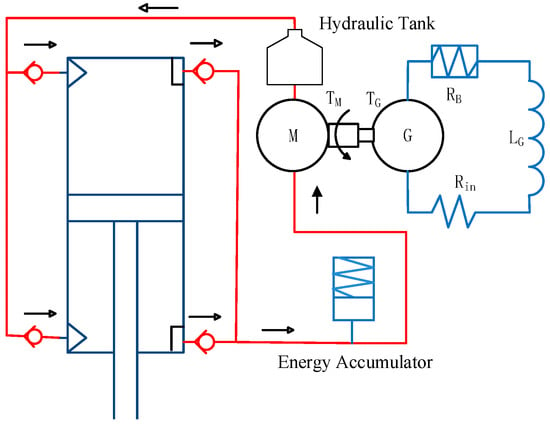
Figure 1.
Schematic diagram of the hydroelectric regenerative damper model.
Due to the asymmetry in piston chamber areas within the hydraulic cylinder, there arises a disparity in volume change during the reciprocating motion of the piston. To mitigate this effect, the accumulator plays a pivotal role in adjusting the pressure differential across the hydraulic cylinder. This ensures the prevention of any stroke voids during piston direction changes, with the opening pressure of the one-way valve set to a lower threshold. In order to facilitate the calculation process within the simulation model, certain simplifications and assumptions have been appropriately applied:
- The model does not incorporate internal leakage between the chambers of the hydraulic cylinder, a common simplification to streamline computational complexity.
- Additionally, the model assumes negligible fluid compressibility within the hydraulic system, utilising Boes’ model to define fluid compressibility. This assumption is often acceptable in hydraulic systems operating within standard pressure ranges.
- In a spring-loaded accumulator, assuming negligible heat exchange between the fluid and the accumulator wall during rapid cycling. Thermal effects resulting from fluid temperature elevation are not accounted for in this study.
- The model assumes constant temperature conditions, disregarding potential variations in oil temperature that could affect viscosity and hydraulic performance. This simplification is made to focus on the core performance metrics without introducing thermal variability.
These simplifications enable a more tractable computational framework for the simulation model, allowing for efficient analysis of the fluid–electric regenerative damper’s dynamic behaviour and performance characteristics. However, it is essential to acknowledge these simplifications when interpreting the simulation results and consider potential deviations from real-world behaviour under certain operating conditions.
- (1)
- Input Excitation
Given the complex and stochastic nature of track excitations experienced in railway systems, simplification is necessary to improve analytical tractability and practical applicability. As a solution, the displacement input from track excitations to the damper can be effectively represented by a sinusoidal excitation formula:
where refers to the superposition of multiple sine waves with different frequencies, represents the amplitude of the sinusoidal excitation, ω denotes the angular frequency, and ϕ represents the phase angle.
- (2)
- Hydraulic rectifier dynamics:
The hydraulic rectifier system in Figure 1 delineates the fluid flow processes inherent to the design. In accordance with Bernoulli’s principle, which encapsulates the conservation of energy within a fluid flow system, several critical aspects merit elucidation and refinement. Bernoulli’s principle posits that within a steady flow of an incompressible fluid, the total mechanical energy per unit mass remains constant along any streamline. This principle can be mathematically expressed as follows:
where P denotes the pressure, presents the fluid density, is the fluid velocity, and is the elevation of the point above a reference plane.
The flow dynamics within the cylinder and check valves can be mathematically described by fundamental principles of fluid mechanics and hydraulic engineering. Specifically, the flow equations governing these components can be described in the following:
- (1)
- Hydraulic cylinder:
The hydraulic cylinder comprises two chambers: one accommodating the piston rod (rod side) and the other devoid of the piston rod (piston side). The cross-sectional area of the piston side exceeds that of the rod side . The flow rates and pressures for compression and extension will be different due to the difference in areas. The volumetric flow rate and the pressure difference across the hydraulic cylinder through the hydraulic cylinder is given as follows:
where and is the cross-sectional area of the piston, and is the velocity of the piston, is the high-pressure side of the hydraulic cylinder (without rod), and is the low-pressure side of the hydraulic cylinder (with rod).
- (2)
- Check Valve:
In the design and analysis of regenerative dampers, understanding the flow characteristics through inline and outline check valves is important.
The flow coefficient represents the valve’s ability to facilitate fluid flow at a given pressure drop. For inline and outline configurations, accurate determination of is imperative for optimising flow directional control and ensuring efficient energy transfer within the regenerative damper system.
The flow rate through a check valve can be expressed using the flow coefficient and the pressure drop across the valve. For an inline check valve, the flow rate is given by the following:
can be expressed as the pressure drop across the check valves, the difference between the inlet pressure , and the outlet pressure :
The flow coefficient, denoted as , and the area of the inline and outline check valve port are crucial parameters that govern the flow characteristics through the valve. The flow coefficient represents the efficiency of the valve in allowing for fluid flow and is defined as the flow rate of fluid at a specified pressure drop across the valve. It quantifies the relationship between the pressure drop across the valve and the flow rate of fluid passing through it. The area of the check valve port denotes as and refers to the cross-sectional area of the valve opening through which fluid flows; a dimensionless flow coefficient factor, representing the valve’s efficiency and geometry. It directly influences the flow capacity of the valve and determines the maximum flow rate that the valve can accommodate under specified conditions. The size and geometry of the port area significantly impact the flow resistance and pressure drop across the valve, thereby affecting the overall performance and efficiency of the hydraulic–electrical regenerative damper system.
The pressure difference at both ends of the one-way valve port can be represented as ; the pressure difference is the result of fluid flow through the valve, where the pressure on the inlet side exceeds that on the outlet side due to flow resistance within the valve.
- (3)
- Hydraulic System Losses:
As referenced in Karpenko and Bogdevičius [27], the pressure loss along the hydraulic pipeline is a critical factor in the design and analysis of hydraulic systems, as it directly impacts the overall efficiency and performance of the hydraulic–electrical regenerative damper. Accurate estimation of pressure loss is essential for ensuring the optimal operation of the damper and achieving effective power regeneration. Understanding and minimising these losses contribute significantly to enhancing the system’s ability to convert mechanical energy into electrical energy efficiently. According to Darcy’s formula, the loss coefficient is given by the following:
where is the length of the pipeline, is the diameter of the pipeline, and is represents the Darcy–Weisbach friction factor, which depends on the Reynolds number () and the roughness of the pipe. Therefore, the loss coefficient can be determined based on the flow regime within the pipeline. The friction factor is given by the following:
Given that () is the kinematic viscosity of the hydraulic oil and is the dynamic viscosity of the hydraulic oil, the pressure loss along the hydraulic pipeline can be expressed:
By substituting into the expressions for , the pressure loss can be more precisely calculated. This allows for an accurate prediction of the pressure dynamics within the hydraulic pipeline of the regenerative damper system.
The effective pressure of the hydraulic motor can be expressed as the difference between the pressure at the inlet and the outlet of the motor, while accounting for pressure losses due to flow resistance in the pipeline and pressure losses within the hydraulic motor , which can be represented as follows:
- (4)
- Torques, generated voltage, and current:
To accurately analyse the performance of the regenerative damper system, it is crucial to account for the various forces and losses involved, particularly the frictional torque between the hydraulic motor and the generator shaft. The frictional torque contributes to pressure loss in the hydraulic motor, which can be expressed as follows:
denotes the pressure loss of the hydraulic motor, presents the frictional resistance coefficient of the hydraulic motor, is the flow rate through the hydraulic motor, is the frictional torque between the hydraulic motor and the generator shaft, and is the angular velocity of the hydraulic motor.
In the regenerative damper system, high-pressure oil flows through the hydraulic motor, which drives the generator to produce electricity. The driving torque required to turn the generator can be expressed as follows:
where is the pressure difference across the hydraulic motor, is the displacement volume of the hydraulic motor per revolution, and is the mechanical efficiency of the hydraulic motor. The power generated by the hydraulic motor is a crucial aspect of the regenerative damper system. The power can be calculated by considering the fluid power delivered to the motor and the losses due to system inefficiencies.
where is the angular velocity of the motor, is the flow rate of the hydraulic motor, and is displacement volume of the hydraulic motor.
For the generator, electromagnetic torque generated by the generator can be represented based on the torque constant coefficient of the generator and the current flowing through the generator’s windings as follows:
The voltage generated by the generator can then be expressed:
where is the back EMF constant and is the angular velocity of the generator.
According to Kirchhoff’s voltage law [28], the generated voltage in the circuit, assuming constant magnetic flux, can be expressed as follows:
where is the internal inductance of the generator, is internal resistance of the generator, and is the external load resistance.
The efficiencies of the motor and generator are treated as constants throughout the operation. While actual efficiencies can vary with different loads and speeds, fixed values are utilised to simplify the computational model and focus on the PSRD system dynamics.
- (5)
- Spring-loaded Accumulator:
In hydraulic systems, the spring-loaded accumulator plays an important role in maintaining pressure stability by storing hydraulic fluid. Although practical considerations such as heat exchange and friction are often neglected for theoretical analysis, the volume change of the spring accumulator can be succinctly expressed as follows:
where represents the effective cross-sectional area of the spring, denotes the displacement of its internal components, is a coefficient representing the sensitivity of volume change to pressure variation, and is the change in pressure within the accumulator.
- (6)
- Damping Force of Hydraulic Cylinder:
The damping force generated by the hydraulic cylinder during both the compression and extension strokes can be analysed through the main force diagram shown in Figure 2. During these strokes, the damping force, denoted as and , respectively, results from the resistance encountered due to the relative motion between the cylinder components.

Figure 2.
Schematic diagram of conventional primary vertical damper forces: compression and extension stroke.
In the compression stroke, the damping force is generated as the damper piston moves downward, causing the fluid within the damper to be forced through restrictive orifices or valves. This resistance to fluid flow translates into a force that opposes the motion of the piston, thereby providing the necessary damping effect. Conversely, during the extension stroke, the damping force is produced when the piston moves upward. Similar to the compression stroke, the upward movement forces the fluid through restrictive pathways, creating resistance and thus generating the damping force that opposes the piston’s motion.
where represents the force of the oil in the rod-free chamber acting on the piston; represents the force of the oil in the rod chamber acting on the piston; represents the mechanical force of the external excitation source acting on the piston rod; represents the friction force of the piston rod oil seal acting on the piston rod; and represents the friction force of the inner wall of the hydraulic cylinder acting on the piston rod. The direction of the friction force is always opposite to the direction of the piston displacement.
- (7)
- Damping force of Regenerative Damper
Incorporating the complexities of hydraulic system dynamics and losses, the damping force expression for the regenerative damper can be formulated as a comprehensive representation of the forces acting on the system. This expression accounts for various factors influencing the damping behaviour, including pressure differentials, flow coefficients, torque generation, and hydraulic losses. By integrating these considerations, a more accurate depiction of the damper’s performance and energy conversion capabilities can be achieved. Damping force expression incorporating pressure, area, torque, and other factors:
where represents the damping force exerted by the regenerative damper; denotes the damping force generated by the hydraulic cylinder due to the reciprocating motion induced by external excitation; is the damping force exerted by the check valve assembly, accounting for resistance to fluid flow; is the damping force generated by the hydraulic motor during operation, influenced by pressure losses, frictional torque, and mechanical inefficiencies; and represents the effective radius of the hydraulic motor’s rotor.
The combined hydraulic and electrical damping effects are represented by an equivalent damping coefficient. This coefficient is derived from established theoretical models and standard values in the literature, streamlining the analysis of the damping characteristics.
Key parameters of the PSRD system are listed in Table 2. These parameters are important for the PSRD system’s effectiveness in reducing vibrations and regenerating power, making it suitable for high-speed rail use.

Table 2.
Key parameters of the PSRD system.
2.2. Vehicle–Rail Coupling Dynamic Model
From a perspective grounded in dynamics and energy management, it is imperative to discern the nuanced disparities between conventional dampers and their regenerative counterparts. Conventional dampers, characterised by a fixed damping coefficient, primarily function to dissipate suspension-induced vibration energy through heat dissipation, thereby mitigating oscillations. In contrast, regenerative dampers present a versatile tuneable aspect, allowing for the adjustment of external resistance loads. This adaptive feature facilitates the fine-tuning of damping characteristics to accommodate diverse road conditions and vehicular dynamics, thereby augmenting overall ride comfort and stability. Furthermore, regenerative dampers epitomise a new approach to energy management, capitalising on the innovative concept of energy harvesting. By converting vibrational energy into electrical power, this system not only addresses vibration attenuation but also harnesses and repurposes this otherwise dissipated energy for practical applications. This innovative approach represents a fundamental change in damping technology, providing advantages including improved ride comfort, reduced wheel wear, enhanced power regeneration, and contribution to sustainable environmental practices.
In this study, the regenerative damper is employed as a replacement for the conventional primary suspension damper. Figure 3 illustrates the components of the energy-harvesting damper integrated into the vehicle model. The vehicle model comprises seven rigid bodies, including the carbody, bogie frames, and wheelsets, along with primary and secondary suspensions. Each rigid body considers six degrees of freedom: vertical, lateral, roll, yaw, pitch, and longitudinal. Consequently, a total of 73 degrees of freedom (DoF) is present in each vehicle, as shown in Table 3. It accounts for the vertical and pitch motions of the carbody and two bogies, as well as the vertical motions of the four wheelsets under random excitations caused by track irregularities. The train is assumed to travel at a constant speed along the track. The regenerative damper system replaces conventional dampers with a design that captures and converts vibrational energy into electrical energy. This substitution not only provides effective vibration mitigation but also leverages the captured energy for practical use, such as powering onboard systems. The regenerative dampers are strategically integrated into the primary suspension, where they play a crucial role in maintaining ride comfort and stability by managing the dynamic interactions between the vehicle and the track.
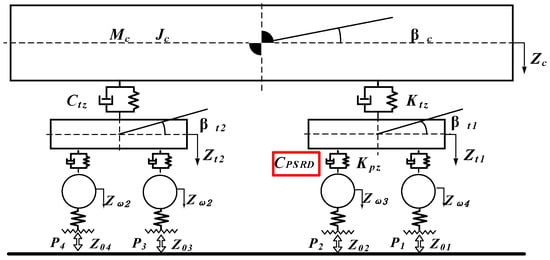
Figure 3.
End view of three-dimensional vehicle–track coupled dynamics.

Table 3.
Degrees of freedom of the high-speed vehicle dynamic model.
The vehicle dynamics model is constructed using multi-body simulation software, capturing the intricate performance of the train under various operating conditions. The model incorporates realistic parameters for mass, stiffness, and damping characteristics, and it simulates the interactions between the train and the track with high fidelity. This detailed modelling approach allows for a comprehensive analysis of the regenerative damper’s performance, including its impact on ride quality, energy harvesting efficiency, and overall vehicle dynamics. This study explores the dynamic response of the train with regenerative dampers under typical track irregularities, assessing their effectiveness in reducing vertical accelerations and enhancing ride comfort. Furthermore, the energy harvesting capability of the dampers is evaluated, demonstrating their potential to convert a significant portion of vibrational energy into usable electrical power. The findings highlight the regenerative damper’s dual functionality in providing superior damping performance while contributing to energy efficiency and sustainability in railway operations.
Since the carbody exhibits pitch motion, the force provided by the primary suspension regenerative damper (PSRD) must be accurately characterised without altering other vehicle components. The dynamic interaction between the PSRD and the carbody involves complex force distributions that account for both vertical and rotational movements. The force provided by the PSRD can be expressed as follows:
2.3. Co-Simulation Approach
In this study, a regenerative damper numerical model and a vehicle–track coupled dynamics model were established using MATLAB and SIMPACK interface, respectively. Co-simulation was achieved through the utilisation of SIMAT, allowing for seamless integration of the two platforms. Additionally, a typical high-speed train model was developed for comparison, as illustrated in Figure 4. The modelling approach employed a substructure technique for both wheelsets and bogies. This method enabled detailed representation of the dynamic interactions within the vehicle system. Based on the parameters of bogie components presented in Table 4, a comprehensive vehicle dynamics model was constructed. This model comprised one carbody, two bogies, four wheelsets, and eight axle boxes. The wheel–rail contact dynamics were simulated using the FASTSIM algorithm, which provided accurate representation of the contact forces and their influence on vehicle behaviour.
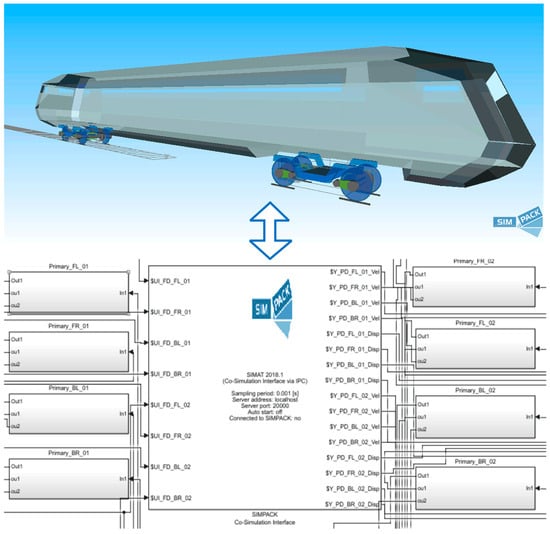
Figure 4.
High-speed train and regenerative damper model and co-simulation setup.

Table 4.
Values of the parameters of a typical passenger rail vehicle.
In parallel, a dynamic system model involving hydraulic components was established using Simulink. This model included hydraulic cylinders, accumulators, hydraulic motors, DC permanent magnet generators, and load circuits. The integration of these elements allowed for analysis of the regenerative damper’s performance and its impact on the vehicle’s overall dynamics. The use of co-simulation facilitated the examination of complex interactions between the mechanical and hydraulic subsystems. By utilising MATLAB and SIMPACK’s capabilities, this study achieved a detailed and accurate representation of the regenerative damper’s behaviour under various operational conditions. This comprehensive approach ensured that the dynamic response of the vehicle, including suspension characteristics and power regeneration capabilities, was analysed.
The calculation models for the dynamic and static characteristics of hydraulic dampers are primarily classified into physical models, equivalent parameter models, and numerical simulation models. The normal vehicle model uses a Maxwell model, which consists of a damping element and a spring element connected in series. According to the European standard BS EN 13802:2013 [29], the equivalent parameter model is a highly recognised theoretical framework for characterising parameters in hydraulic damper performance tests. The model provides an effective reference for the preliminary verification of the regenerative damper’s adaptability.
Track irregularity is the principal source of excitation for vibration dampers, and different track excitations significantly influence the vibration attenuation and power generation performance. To ensure that the research aligns closely with real-world conditions, this study utilises measured track irregularity data from a specific railway in China as the track spectrum, as shown in Figure 5. Applying actual track irregularity data ensures that the analysis reflects real operational conditions providing a realistic assessment of the damper’s performance. It also allows for a direct comparison of the regenerative damper’s performance with that of conventional primary vertical dampers, highlighting the regenerative damper’s advantages in terms of vibration reduction, wheel wear reduction, and power regeneration.
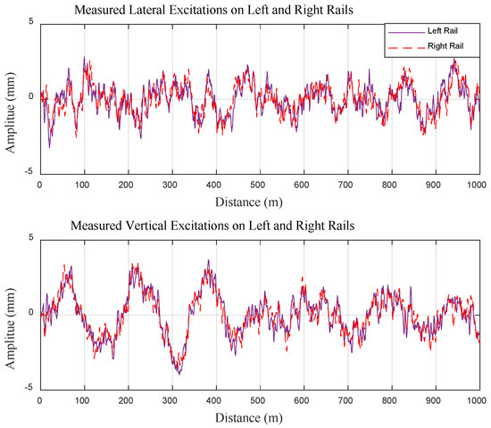
Figure 5.
Lateral and vertical irregularities applied on both left and right rails.
3. Simulation and Analysis
To investigate the vertical dynamic characteristics of a PSRD model, this study uses the CRH380A high-speed train as a case study. The high-speed railway WG line track spectrum is adopted as the input excitation for the train system. Dynamics simulations are performed using both a conventional primary vertical damper force element vehicle model and an integrated PSRD vehicle model to analyse the similarities and differences between both. The simulations aim to evaluate key performance metrics such as ride comfort, power regeneration efficiency, and wheel wear performance. By employing the PSRDs into vehicle model, this study seeks to quantify the benefits of the regenerative damper in mitigating vertical vibrations and enhancing power regeneration capabilities. Analysis in this section is crucial for understanding how regenerative dampers can improve the dynamic performance of high-speed trains while contributing to sustainable energy practices. The findings from these simulations are expected to inform the design and optimisation of future regenerative damper systems, paving the way for more efficient and environmentally friendly railway technologies.
3.1. Multi-Body Coupled Dynamic Response
Given the consistent pattern of vertical dynamic responses observed in high-speed trains across varying speeds, this study centres on a comparative analysis of the acceleration and displacement responses of two models, specifically at a speed of 350 km/h. This speed is chosen as it represents a common operational velocity for high-speed trains, providing a relevant benchmark for evaluating dynamic performance.
The analysis is conducted in both the time and frequency domains to offer a comprehensive understanding of the vertical dynamics. Time domain analysis focuses on the real-time behaviour of the train, capturing instantaneous carbody and bogie acceleration, and PSRD and conventional primary vertical damper displacement responses to track irregularities.
The analysis results presented in Figure 6, Figure 7, Figure 8, Figure 9 and Figure 10 highlight how the PSRD model, when equipped with the vehicle model, effectively reduces carbody and bogie vibrations. It can reduce peak acceleration values of carbody and bogie centre, indicating a smoother ride quality and better vibration mitigation. In Figure 8, the displacement responses between the PSRD and conventional primary vertical damper further confirm the effectiveness of the regenerative damper in maintaining stability and reducing vertical oscillations.
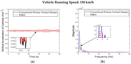
Figure 6.
Carbody centre vertical acceleration at the speed of 150 km/h: (a) time domain; (b) frequency domain.
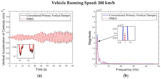
Figure 7.
Carbody centre vertical acceleration at the speed of 200 km/h: (a) time domain; (b) frequency domain.
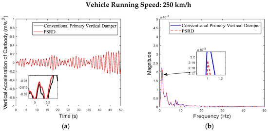
Figure 8.
Carbody centre vertical acceleration at the speed of 250 km/h: (a) time domain; (b) frequency domain.
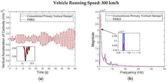
Figure 9.
Carbody centre vertical acceleration at the speed of 300 km/h: (a) time domain; (b) frequency domain.
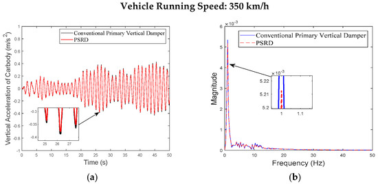
Figure 10.
Carbody centre vertical acceleration at the speed of 350 km/h: (a) time domain; (b) frequency domain.
Figure 6, Figure 7, Figure 8, Figure 9, Figure 10, Figure 11, Figure 12, Figure 13, Figure 14, Figure 15, Figure 16, Figure 17, Figure 18, Figure 19 and Figure 20 provide detailed insights into the vertical dynamics of the high-speed train’s carbody, bogie, and primary suspension, comparing the conventional damper force element vehicle model with the integrated PSRD vehicle dynamics model. According to other researchers’ studies [30], which focused on similar high-speed train dynamics, the carbody primarily experiences low-frequency vibrations (0–2 Hz), while the bogie shows vibrations across a broader spectrum up to 50 Hz. The simulated vertical accelerations of the carbody and bogie closely align with these findings, with the carbody staying below 1 m/s2 and the bogie reaching approximately 4 m/s2, validating the simulation results presented in this study.
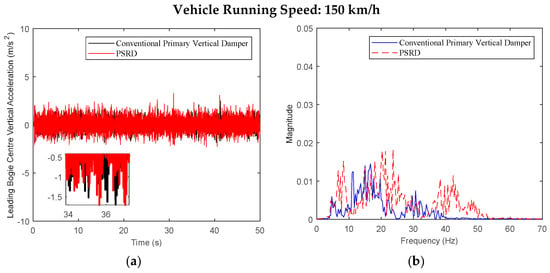
Figure 11.
Leading bogie centre vertical acceleration at the speed of 150 km/h: (a) time domain; (b) frequency domain.
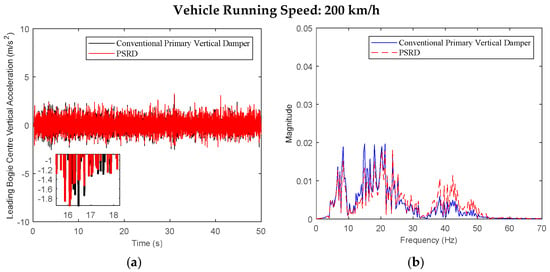
Figure 12.
Leading bogie centre vertical acceleration at the speed of 200 km/h: (a) time domain; (b) frequency domain.
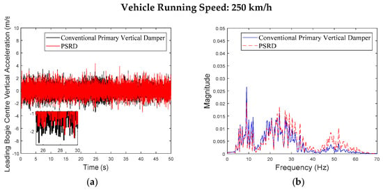
Figure 13.
Leading bogie centre vertical acceleration at the speed of 250 km/h: (a) time domain; (b) frequency domain.
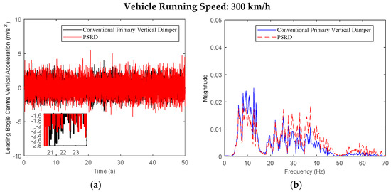
Figure 14.
Leading bogie centre vertical acceleration at the speed of 300 km/h: (a) time domain; (b) frequency domain.
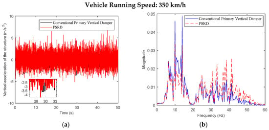
Figure 15.
Leading bogie centre vertical acceleration at the speed of 350 km/h: (a) time domain; (b) frequency domain.
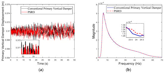
Figure 16.
Primary vertical damper displacement of the leading wheelset at the speed of 150 km/h: (a) time domain; (b) frequency domain.
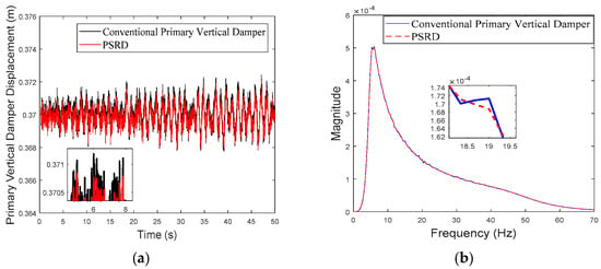
Figure 17.
Primary vertical damper displacement of the leading wheelset at the speed of 200 km/h: (a) time domain; (b) frequency domain.
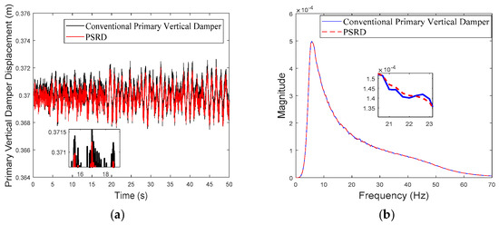
Figure 18.
Primary vertical damper displacement of the leading wheelset at the speed of 250 km/h: (a) time domain; (b) frequency domain.
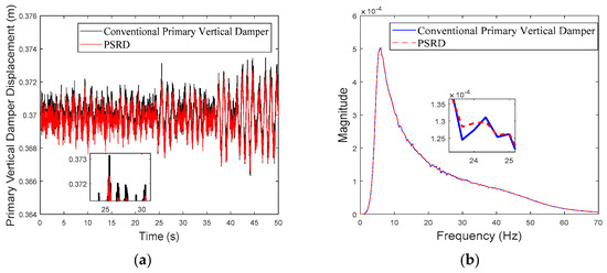
Figure 19.
Primary vertical damper displacement of the leading wheelset at the speed of 300 km/h: (a) time domain; (b) frequency domain.
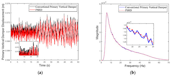
Figure 20.
Primary vertical damper displacement of the leading wheelset at the speed of 350 km/h: (a) time domain; (b) frequency domain.
While both the conventional primary vertical damper and PSRD models show similar trends in vibration energy distribution, notable differences arise in vibration amplitudes across different frequency ranges. Specifically, within the critical frequency band of 1 Hz to 20 Hz for the carbody, the PSRD model demonstrates slightly reduced amplitudes compared to the conventional model. This reduction indicates the PSRD system’s effectiveness in attenuating primary vertical vibration frequencies, contributing to improved ride comfort and stability. The frequency domain analysis highlights the PSRD system’s capability to respond effectively to varying vibration frequencies encountered in high-speed train operations. This capability is crucial for maintaining passenger comfort and operational stability across a range of speeds from 150 km/h to 350 km/h, as shown in the simulation. The observed differences in bogie vertical vibrations between 20 Hz and 60 Hz, where the PSRD system shows controlled variations compared to conventional dampers, underscore its potential for managing high-frequency oscillations more efficiently. This study identifies significant challenges related to force fluctuations during directional changes in excitation, primarily influenced by high electromagnetic accelerations affecting generator inertia. In configurations with multiple hydraulic components in series, fluid flow dynamics give fluctuations, with less pronounced fluid inertia effects due to the small displacement volume per stroke.
Overall, the analysis of Figure 6, Figure 7, Figure 8, Figure 9, Figure 10, Figure 11, Figure 12, Figure 13, Figure 14, Figure 15, Figure 16, Figure 17, Figure 18, Figure 19 and Figure 20 confirms the PSRD system’s viability in enhancing high-speed train performance by mitigating vibrations across various operational speeds. Future research will focus on optimising damping characteristics and exploring advanced control strategies to further enhance the PSRD system’s effectiveness in real-world applications, thereby improving passenger comfort and operational safety in high-speed rail transport.
3.2. Comparison of Wear Index
Wheel–rail wear is linked to the energy dissipated within the wheel–rail contact patch, which manifests in the form of wear power exerted on the contacting surfaces. A fundamental metric in assessing this wear phenomenon is the Elkins wear index, which offers a comprehensive evaluation of the interaction between wheel and rail. This index encapsulates the cumulative effect of creep forces and creepages at the contact patch, providing valuable insights into the wear condition. Expressed mathematically, the wear index is computed as the scalar product of creep forces and creepages, thereby quantifying the extent of wear between the wheel and rail. It serves as a parameter in the wear model, denoting the wear power within the contact patch. The wear index is instrumental in characterising wheel–rail wear dynamics and is instrumental in elucidating wear-related issues within railway systems.
where , and —longitudinal, transverse, and spin creep forces; , , and —Z-longitudinal, transverse, and spin creep rates. The computation of the wear index entailed an analysis of longitudinal, lateral, and spin creep rates, coupled with corresponding creep forces derived from the simulation data. Employing the wear power model, the wear index was systematically calculated to discern the dynamic wear patterns between the wheel and rail surfaces. Throughout the simulation, particular emphasis was placed on comparing the wear index and its root mean square (RMS) values across distinct operational phases of the train, including constant speed, acceleration, and deceleration. This comprehensive approach enabled a good understanding of wear dynamics under varying speed conditions, illuminating key factors affecting wheel–rail contact and wear patterns.
The comparison between the conventional primary vertical damper-based vehicle model and the integrated PSRD vehicle model, as shown in Figure 21, Figure 22 and Figure 23, reveals a consistent trend in their instantaneous wear indices. Notably, the wear index of the integrated PSRD vehicle model tends to demonstrate a slightly lower magnitude compared to that of the conventional primary vertical damper vehicle model. The finding suggests that the proposed PSRD design and functionality can contribute to reduced wear between the wheel and rail interfaces. Furthermore, an analysis of vehicle operation at various speeds, including constant speed, acceleration, and deceleration, indicates a variable trend in wear work with changes in velocity. The dynamic behaviour underscores the complex interplay between vehicle dynamics, track conditions, and operational parameters, all of which influence wear patterns and energy dissipation within the wheel–rail interface. By comparing the RMS values of wear, the PSRD vehicle model shows lower wear numbers than its conventional counterpart. These findings have significant implications for rail infrastructure maintenance and cost management. By potentially reducing wheel–rail wear, the PSRD could contribute to extending wheel–rail service life and lowering maintenance expenditures over the long term. The simulation results provide valuable insights into the effectiveness of the proposed PSRD design in mitigating wear-related challenges in railway operations.
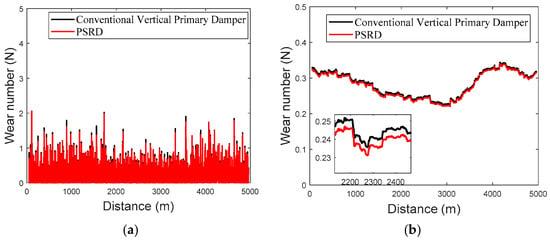
Figure 21.
(a) Linear constant speed 350 km/h wear index; (b) root mean square value of linear constant speed 350 km/h wear index.
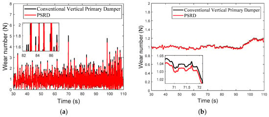
Figure 22.
(a) Wear index under linear acceleration condition; (b) root mean square value of wear index under uniform linear acceleration condition.
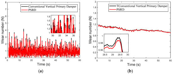
Figure 23.
(a) Wear index under linear deceleration condition; (b) root mean square value of wear index under uniform linear deceleration condition.
3.3. Comfort Analysis
The PSRD provides an important role in mitigating vertical vibrations transmitted from the wheels to the bogie, encompassing both pitch and heave motions. This function is critical for enhancing passenger comfort by minimising perceptible track irregularities and dynamic forces during high-speed train operations.
High-speed trains are complex multi-body dynamic systems characterised by intricate interactions among lateral, longitudinal, and vertical degrees of freedom. Accelerations induced by track irregularities, traction, and braking forces propagate through interconnected components such as the carbody, primary and secondary suspensions, wheel–rail interface, and coupler connections, profoundly influencing passenger comfort. The performance of the PSRD impacts overall ride quality and operational stability. While performances like stability metrics such as hunting critical speeds and safety considerations during curve negotiation are critical, optimising ride smoothness and passenger comfort remains a primary objective. It is particularly important during high-speed operation, where minimising vertical accelerations and controlling pitch and yaw motions are essential for passenger comfort and operational efficiency.
Simulation parameters were chosen to predict typical operational conditions of high-speed rail networks, emphasising long straight sections and large-radius curves (Table 5). These conditions are instrumental in evaluating the RSD’s effectiveness at a train speed of 350 km/h, a pivotal benchmark for assessing ride stability and comfort. Through effective damping of oscillations within primary frequency ranges associated with track-induced vibrations, the RSD enhances overall ride comfort. This not only improves the passenger experience but also contributes to operational efficiency and safety in high-speed train services.

Table 5.
Track characteristics of a high-speed railway line.
In this study, the analysis of comfort adheres to the rigorous criteria set forth by the BS EN12299:2009 [31] standard. This standard outlines a comprehensive methodology for assessing ride comfort in railway applications, considering factors such as carbody centre, and pivot 1 and pivot 2 accelerations in the longitudinal, lateral, and vertical directions.
According to the BS EN 12299:2009 standard for ride comfort in railway applications, the proposed methodology follows a structured approach. Initially, it filters the time history of carbody accelerations, capturing data in the longitudinal, lateral, and vertical directions, and then the calculated RMS values of the accelerations are computed at 5 s intervals, providing a comprehensive overview of the dynamic behaviour of the vehicle over time. Additionally, the 95th percentile acceleration outputs are determined, capturing acceleration events that impact passenger comfort. These values, denoted as , , and for the longitudinal, lateral, and vertical directions, respectively, serve as key indicators in the assessment process:
where W is the weighted frequency value in accordance with the x-axis (X-longitudinal direction) and y-axis (Y-lateral direction), W is the weighted frequency value in accordance with the z-axis (Z-vertical direction), and P is the interface. Based on the specific focus on ride comfort indices (), a standardised framework for ride comfort indications was established, as shown in Table 6.

Table 6.
Ride comfort indices.
Table 7 presents the ride comfort assessment based on the 95th percentile weighted RMS acceleration (mean ride comfort) under different track conditions. As shown in Figure 24, the ride comfort indices show a consistent trend across various track scenarios, indicating the effectiveness of the PSRD system in maintaining passenger comfort.

Table 7.
Ride comfort assessment (95th percentile weighted RMS acceleration (mean ride comfort)) under different track.
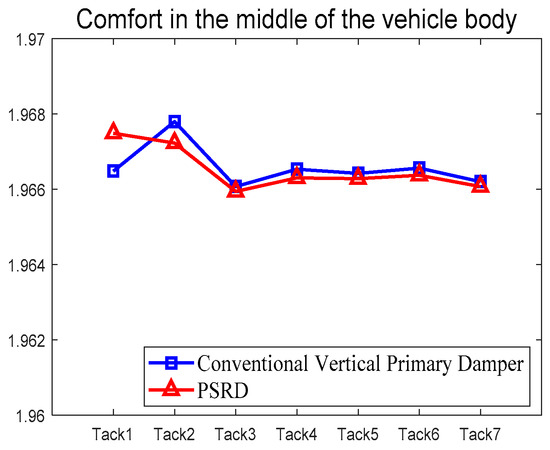
Figure 24.
Comparison of comfort levels in the middle of the vehicle body.
By comparing the comfort indices derived from the two models, it was noted that the comfort level fell within the range between 1.96 and 1.97, consistent with established comfort standards for railway vehicles. Notably, the maximum relative deviation was less than 0.1%, signifying a remarkable level of conformity in the predicted results. The degree of consistency lends credence to the accuracy and dependability of the proposed PSRD integrated vehicle model. Moreover, the damping characteristics exhibited by PSRD align well with the comfort requirements of high-speed trains, highlighting its efficacy in meeting comfort demands.
3.4. Power Regeneration Analysis
Vertical dampers play an important role in absorbing the unexpected vibration from track irregularities. Through the implementation of regenerative damper technology, the vibrational energy can be recovered and repurposed. By adjusting the electrical load, the PSRD not only provides an optimal damping coefficient to reduce vibrations but also converts vibrational energy into electrical energy. Regenerated power is then stored in batteries, facilitating semi-active control elements or self-powered devices. In this study, a model of an equivalent DC permanent magnet generator was developed and integrated into the primary suspension system, achieving efficient energy conversion and storage. The specific integration ensures that the vibrational energy recovered is converted and stored effectively, contributing to the overall energy efficiency of the vehicle system. In this study, it is assumed that all types of losses in the electrical conversion and storage process, including rotational friction losses, electrical resistive losses, inductive losses, and load matching efficiency, are considered and incorporated into the overall power generation efficiency.
The input power of the hydraulic cylinder, which is pivotal in this energy conversion process, is detailed as follows:
The power regeneration output is then expressed:
The power regeneration efficiency is written as below:
where Trf is the rotational friction torque of the motor and generator.
To investigate the power regeneration and efficiency of regenerative dampers, simulations were conducted at a vehicle speed of 350 km/h. The simulations were based on real-world conditions of a 5 km railway line in a specific region of China, as detailed in Table 6. The simulation results, shown in Figure 25 and Figure 26 and Table 8, provide a comprehensive analysis of the power generation capabilities and efficiency of the regenerative damper system under high-speed operation. The findings offer valuable insights into the practical application and performance of the PSRD in real-world scenarios, highlighting their potential to enhance power regeneration and improve overall system efficiency.
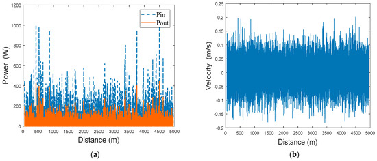
Figure 25.
(a) Comparison of input power and output power; (b) instantaneous speed of damper.
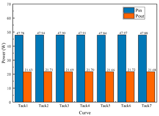
Figure 26.
Comparison of average power of a single damper under different track conditions.

Table 8.
Energy conversion efficiency of individual dampers.
As illustrated in Figure 25, a comparative analysis of the instantaneous input and output power of an individual damper is presented. The maximum instantaneous input power can reach approximately 996 W, while the maximum output power is up to 450 W, with the damper’s instantaneous velocity hovering around 0.15 m/s. Figure 26 illustrates the average input and output power of the each PSRD, revealing that when the vehicle travels at a speed of 350 km/h through seven distinct 5 km curves, the power generation efficiency averages 21.6 W, and the power regeneration efficiency can reach around 45.28 % as shown in Table 8. It indicates that the power regenerated from the PSRD is sufficient to power small electrical components in the bogie, thereby enabling effective energy recuperation. The study highlights the potential of the proposed PSRD in enhancing the power regeneration efficiency of high-speed trains. By converting vibrational energy into electrical energy, the PSRDs not only reduce the energy dissipated as heat but also provide a valuable source of power for auxiliary systems. The proposed approach aligns with sustainable practices by improving the overall energy utilisation of the railway system and reducing the dependency on external power sources. The practical implications of these findings are significant, as it demonstrates the feasibility and effectiveness of integrating regenerative damper technology into modern high-speed rail networks for improved energy management and sustainability.
4. Preliminary Experimental Validation
Based on the schematic in Figure 1, the parameters of the key components are listed in Table 2. A corresponding test rig was designed and fabricated according to the design concept and model development principles (Figure 27) to validate the predictions of the developed PSRD model. The test bench was equipped with essential components of the PSRD system, including a hydraulic cylinder, spring-loaded accumulator, hydraulic motor, generator, check valves, and piping, to facilitate accurate data collection and ensure thorough evaluation of the system’s performance.
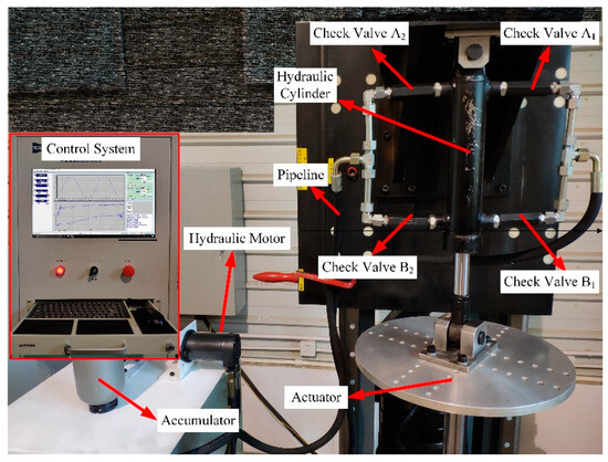
Figure 27.
The PSRD test rig.
The force–displacement loop and regenerated power measurements, using 1 Hz, 20 mm sine wave excitation, demonstrates good agreement between the predicted and measured equivalent damping force and power regeneration. The setup includes a 0.5 L spring-loaded accumulator, a 20 Ω external load resistance, and a 20 Ω internal load resistance, as shown in Figure 28. The results indicate that the system could produce an acceptable damping force, peaking at 12.5 kN, and the regenerated power is approximately 230 W. The preliminary tests validate the PSRD model’s performance in a controlled environment, demonstrating its potential for effective energy harvesting and vibration damping. Given the constraints at this stage, the experiments focus on the PSRD system in isolation. However, these initial successes pave the way for future integration and testing.
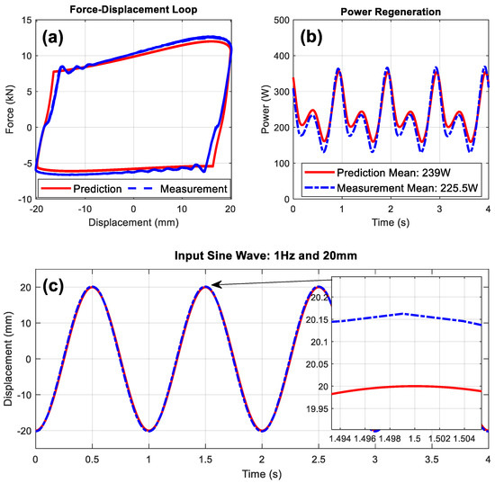
Figure 28.
The validation of (a) force–displacement loop, (b) regenerated power, and (c) input sine wave excitation.
The PSRD system is planned to replace the primary vertical dampers in railway vehicles for comprehensive line testing under real-world conditions. Such testing will provide a more robust validation of the system’s effectiveness and is crucial for the sustainable development of high-speed rail systems, potentially offering significant improvements in energy efficiency and ride comfort. Future tests will involve rigorous evaluations of the system’s performance in dynamic railway environments, investigating impacts such as vibration responses, wheel wear, ride comfort indices, and overall power generation. The insights gained from the line tests will be invaluable in refining the PSRD system and ensuring its readiness for widespread application in railway transportation.
5. Conclusions
This study examines the influence of integrating a primary suspension regenerative damper (PSRD) into the primary vertical damper of railway vehicles on power regeneration performance, bogie dynamics, and wheel–rail wear. A comparative analysis was conducted using the high-speed train model under identical operating conditions, followed by a detailed simulation. The key findings are as follows:
- (1)
- At a constant speed range of 150–350 km/h, increasing in increments of 50 km/h, the time and frequency domain responses of the carbody and bogie vertical accelerations and damper travel of the PSRD vehicle closely align with those of conventional primary vertical damper vehicle. Notably, the vertical acceleration amplitude slightly increases between 20 Hz and 60 Hz. The increase is attributed to the pressure time-varying nonlinear components in the PSRD, deviating from ideal linearity and causing fluctuations in speed inputs at both ends of the damper.
- (2)
- The adaptability of vehicle operation with the PSRD was assessed through a comparative analysis of the wear index size and distribution. The results indicated consistent wear index values for both conventional primary damper vehicles and integrated PSRD vehicles under varying conditions of acceleration, constant speed, and deceleration. It demonstrates that the PSRD maintains comparable wear characteristics to traditional damping systems.
- (3)
- Utilising actual railway conditions measured in a specific region of China, this study conducted a comprehensive comfort analysis and power generation assessment. The train comfort remained largely consistent across different curve scenarios, due to the standards for passenger comfort. Additionally, the average power generation of a single PSRD was 21.72 W over a 5 km operating distance, with a power generation efficiency of 45.28%.
- (4)
- The test rig validation of the PSRD model demonstrated a peak damping force of 12.5 kN and approximately 230 W of regenerated power, showing good agreement with the predicted values under 1 Hz, 20 mm sine wave excitation with 20 Ω load resistances.
- (5)
- Future work involves replacing the primary vertical dampers in railway vehicles with the PSRD system and conducting comprehensive real-world testing to evaluate its impact on vibration responses, wheel wear, ride comfort indices, and overall energy efficiency in dynamic rail environments.
The findings highlight the dual benefits of the proposed PSRD used in this study. It not only ensures excellent damping performance but also shows significant power regeneration capability, making it a valuable addition to modern railway systems. The integration of PSRDs offers a promising avenue for enhancing the sustainability and efficiency of high-speed rail networks by harnessing vibrational energy that would otherwise be dissipated as waste.
Author Contributions
H.W.: Conceptualisation, Methodology, Modelling, Analysis, and Writing. G.F.: Supervision, Validation, Visualization and Writing—review & editing. X.Z., H.W. and R.W.: Reviewing and Editing. H.W. and R.W.: Revising and Editing. All authors have read and agreed to the published version of the manuscript.
Funding
Natural Science Foundation of Hebei Province (A2023210026) and the Open Project of the State Key Laboratory of Rail Transit Vehicle System (RVL2405).
Data Availability Statement
Available on request.
Acknowledgments
Shijiazhuang Tiedao University is licensed by Dassault Systems Deutschland GmbH to use the SIMPACK 2018.1. The authors gratefully acknowledge Shijiazhuang Tiedao University and the support of the State Key Laboratory of Rail Transit Vehicle System at Southwest Jiaotong University.
Conflicts of Interest
The authors declare that this research was conducted in the absence of any commercial or financial relationships that could be construed as a potential conflict of interest.
References
- Fu, C.; Lu, J.; Ge, W.; Tan, C.; Li, B. A Review of Electromagnetic Energy Regenerative Suspension System & Key Technologies. CMES-Comput. Model. Eng. Sci. 2023, 135, 1779–1824. [Google Scholar]
- Pasha, S.K.; Champa, V. Design and Development of Regenerative Suspension System for EV Applications. In Proceedings of the 2023 IEEE International Conference on Power Electronics, Smart Grid, and Renewable Energy (PESGRE), Trivandrum, India, 17–20 December 2023; pp. 1–5. [Google Scholar]
- Ali, A.; Ahmed, A.; Ali, M.; Azam, A.; Wu, X.; Zhang, Z.; Yuan, Y. A review of energy harvesting from regenerative shock absorber from 2000 to 2021: Advancements, emerging applications, and technical challenges. Environ. Sci. Pollut. Res. 2023, 30, 5371–5406. [Google Scholar] [CrossRef]
- Galluzzi, R.; Circosta, S.; Amati, N.; Tonoli, A. Performance comparison between electromechanical and electro-hydrostatic regenerative shock absorbers. IOP Conf. Ser. Mater. Sci. Eng. 2022, 1214, 012012. [Google Scholar] [CrossRef]
- Ahmad, M.; Bhatti, A.H.; Ashraf, M.M. Energy Recovery Using Regenerative Suspension System. In Proceedings of the 2024 7th International Conference on Energy Conservation and Efficiency (ICECE), Lahore, Pakistan, 6–7 March 2024; pp. 1–6. [Google Scholar]
- Liu, Y.; Xu, L.; Zuo, L. Design, modeling, lab, and field tests of a mechanical-motion-rectifier-based energy harvester using a ball-screw mechanism. IEEE/ASME Trans. Mechatron. 2017, 22, 1933–1943. [Google Scholar] [CrossRef]
- Suda, Y.; Shiiba, T. A new hybrid suspension system with active control and energy regeneration. Veh. Syst. Dyn. 1996, 25, 641–654. [Google Scholar] [CrossRef]
- Mohrlock, D.; Schindler, A.; Beringer, H.; Schmitt, J. Torsion Spring System for a Wheel Suspension of a Motor Vehicle. U.S. Patent 9,393,848, 19 July 2016. [Google Scholar]
- Mohrlock, D.; Schindler, A.; Beringer, H.; Schmitt, J. Torsion Bar Spring Arrangement for a Wheel Suspension of a Motor Vehicle. U.S. Patent 9,108,482, 18 August 2015. [Google Scholar]
- Gupta, A.; Jendrzejczyk, J.; Mulcahy, T.; Hull, J. Design of electromagnetic shock absorbers. Int. J. Mech. Mater. Des. 2006, 3, 285–291. [Google Scholar] [CrossRef]
- Avadhany, S.N. Analysis of Hydraulic Power Transduction in Regenerative Rotary Shock Absorbers as Function of Working Fluid Kinematic Viscosity. Bachelor’s Thesis, Massachusetts Institute of Technology, Cambridge, MA, USA, 2009. [Google Scholar]
- Miraglia, M.; Tannous, M.; Inglese, F.; Brämer, B.; Milazzo, M.; Stefanini, C. Energy recovery from shock absorbers through a novel compact electro-hydraulic system architecture. Mechatronics 2022, 81, 102701. [Google Scholar] [CrossRef]
- Wang, Z.; Zhang, T.; Zhang, Z.; Yuan, Y.; Liu, Y. A high-efficiency regenerative shock absorber considering twin ball screws transmissions for application in range-extended electric vehicles. Energy Built Environ. 2020, 1, 36–49. [Google Scholar] [CrossRef]
- Zhang, R.; Wang, X.; John, S. A comprehensive review of the techniques on regenerative shock absorber systems. Energies 2018, 11, 1167. [Google Scholar] [CrossRef]
- Stosiak, M.; Karpenko, M. The influence of the hydropneumatic accumulator on the dynamic and noise of the hydrostatic drive operation. Eksploat. I Niezawodn.–Maint. Reliab. 2024, 26, 1–11. [Google Scholar] [CrossRef]
- Pan, H.; Qi, L.; Zhang, Z.; Yan, J. Kinetic energy harvesting technologies for applications in land transportation: A comprehensive review. Appl. Energy 2021, 286, 116518. [Google Scholar] [CrossRef]
- Li, S.; Xu, J.; Pu, X.; Tao, T.; Gao, H.; Mei, X. Energy-harvesting variable/constant damping suspension system with motor based electromagnetic damper. Energy 2019, 189, 116199. [Google Scholar] [CrossRef]
- Zhang, X.; Zhang, Z.; Pan, H.; Salman, W.; Yuan, Y.; Liu, Y. A portable high-efficiency electromagnetic energy harvesting system using supercapacitors for renewable energy applications in railroads. Energy Convers. Manag. 2016, 118, 287–294. [Google Scholar] [CrossRef]
- Zhang, X.; Pan, H.; Qi, L.; Zhang, Z.; Yuan, Y.; Liu, Y. A renewable energy harvesting system using a mechanical vibration rectifier (MVR) for railroads. Appl. Energy 2017, 204, 1535–1543. [Google Scholar] [CrossRef]
- Ruichen, W.; Paul, A.; Yang, S.; Zhiwei, W. Modelling and Analysis of Power-Regenerating Potential for High-Speed Train Suspensions. Sustainability 2022, 14, 2542. [Google Scholar] [CrossRef]
- Pan, Y.; Guo, S.; Jiang, R.; Xu, Y.; Tu, Z.; Zuo, L. Performance evaluation of train suspension energy harvesting shock absorber on railway vehicle dynamics. In Proceedings of the ASME 2018 Dynamic Systems and Control Conference, Atlanta, GA, USA, 30 September–3 October 2018; p. V003T042A005. [Google Scholar]
- Wang, R.; Wang, Z. Evaluation of power regeneration in primary suspension for a railway vehicle. Front. Mech. Eng. 2020, 15, 265–278. [Google Scholar] [CrossRef]
- Dai, J.; Ang, K.K.; Luong, V.H.; Tran, M.T.; Jiang, D. Out-of-plane responses of overspeeding high-speed train on curved track. Int. J. Struct. Stab. Dyn. 2018, 18, 1850132. [Google Scholar] [CrossRef]
- Liu, C.; Thompson, D.; Griffin, M.J.; Entezami, M. Effect of train speed and track geometry on the ride comfort in high-speed railways based on ISO 2631-1. Proc. Inst. Mech. Eng. Part F J. Rail Rapid Transit 2020, 234, 765–778. [Google Scholar] [CrossRef]
- Sun, W.; Zhou, J.; Thompson, D.; Gong, D. Vertical random vibration analysis of vehicle–track coupled system using Green’s function method. Veh. Syst. Dyn. 2014, 52, 362–389. [Google Scholar] [CrossRef]
- Karpenko, M.; Bogdevičius, M. Investigation of Hydrodynamic Processes in the System—“Pipeline-Fittings”. In TRANSBALTICA XI: Transportation Science and Technology (TRANSBALTICA 2019); Gopalakrishnan, K., Prentkovskis, O., Jackiva, I., Junevičius, R., Eds.; Springer: Cham, Switzerland, 2020; pp. 331–340. [Google Scholar]
- Wang, R.; Gu, F.; Cattley, R.; Ball, A.D. Modelling, testing and analysis of a regenerative hydraulic shock absorber system. Energies 2016, 9, 386. [Google Scholar] [CrossRef]
- Eremia, M.; Shahidehpour, M. Handbook of Electrical Power System Dynamics: Modeling, Stability, and Control; John Wiley & Sons: Hoboken, NJ, USA, 2013. [Google Scholar]
- BS EN 13802:2013; Railway Applications. Suspension Components. Hydraulic Dampers. The British Standards Institution: London, UK, 2013.
- Ren, Z.; Liu, Z. Vibration and frequency domain characteristics of high speed EMU. J. Mech. Eng. 2013, 49, 1–7. [Google Scholar] [CrossRef]
- BS EN 12299:2009; Railway Applications. Ride Comfort For Passengers. Measurement And Evaluation. The British Standards Institution: London, UK, 2009.
Disclaimer/Publisher’s Note: The statements, opinions and data contained in all publications are solely those of the individual author(s) and contributor(s) and not of MDPI and/or the editor(s). MDPI and/or the editor(s) disclaim responsibility for any injury to people or property resulting from any ideas, methods, instructions or products referred to in the content. |
© 2024 by the authors. Licensee MDPI, Basel, Switzerland. This article is an open access article distributed under the terms and conditions of the Creative Commons Attribution (CC BY) license (https://creativecommons.org/licenses/by/4.0/).