Article

State-of-Charge Estimation for Lithium-Ion Battery Base on Adaptive Extended Sliding Innovation Filter

College of Information Science and Enginnering, Hohai University, Changzhou 213200, China
*
Author to whom correspondence should be addressed.
Energies 2024, 17(14), 3495; https://doi.org/10.3390/en17143495
Submission received: 15 May 2024 / Revised: 4 July 2024 / Accepted: 14 July 2024 / Published: 16 July 2024

Abstract

:
Accurate State of Charge (SoC) estimation is pivotal in advancing battery technology. In order to enhance the precision of SoC estimation, this study introduces the 2RC equivalent circuit model for lithium batteries. The Adaptive Extended Sliding Innovation Filter (AESIF) algorithm merges the model’s predictive outcomes with observation results. However, further improvements are required for this algorithm to perform optimally in strong noise environments. By adapting to observation noise and utilizing PID control to adjust the sliding boundary layer, the algorithm can accommodate varying noise levels and control interference fluctuations within specific limits. This study enhances the AESIF algorithm in these areas, proposing an improved version (IAESIF) to elevate performance in strong noise environments and improve overall estimation accuracy. Comprehensive tests were conducted under diverse operational conditions and temperatures, with results indicating that, compared to the EKF and the AESIF algorithm in strong noise environments, the IAESIF algorithm demonstrates improved noise adaptation and overall estimation accuracy.

1. Introduction

The ever-growing range requirement of electrified transportation not only proposes strong requests for high-energy-density lithium-ion batteries, but also addresses the accompanying limitations related to cycling stability and safety issues [1,2]. The State of Charge (SoC) of a battery, as a key parameter of the battery [3], not only helps the Battery Management System (BMS) to achieve efficient charging and discharging strategies and increase cycle stability, but also provides important references for battery safety [4]. However, SoC is not a directly measurable quantity; it needs to be calculated based on indicators such as terminal voltage [5,6].
In the literature, several techniques have been proposed to estimate the SoC. The most popular method has been the ampere-hour counting method. This method makes use of current measurements and the battery’s capacity to estimate the SoC of the battery. Unfortunately, this method is highly dependent on an accurate initial SoC value and sensor current measurements. Additionally, the ampere-hour counting method utilizes the battery’s available capacity, which has been shown to decrease over time, leading to increased errors during regular battery use [7]. These issues can be addressed by integrating techniques like neural networks (NNs) and the Kalman Filter (KF) to minimize errors by combining prediction and observation results [8,9]. While neural networks demand high computing power, the Kalman Filter relies on mathematical models, offering cost-effective and accurate solutions. It is currently considered one of the most efficient and promising methods available [10].
The ongoing development and research of mathematical models encompass various types, such as empirical models, electrochemical models, and equivalent circuit models. These models are utilized to characterize battery behavior and accurately gauge the SoC. The widely employed equivalent circuit model offers high computational efficiency and relatively low complexity. It comprises internal resistance and a series of RC branches to depict transient responses. While adding RC branches can enhance model accuracy, it also escalates computational complexity. Therefore, it is crucial to strike a balance between computational accuracy and complexity by selecting an appropriate number of RC branches [11].
Based on the equivalent circuit model and the ampere-hour counting method, combined with the Kalman Filter, it demonstrates high accuracy in estimating SoC [9]. In practical applications, SoC, being an indirectly obtained quantity, is susceptible to various interferences, and the resulting errors can significantly affect its accuracy, especially in the presence of strong interference. However, for the estimation problem involving uncertainty and interference, there is a superior alternative to the Kalman Filter. A research team has introduced the Sliding Innovation Filter (SIF) algorithm, which represents an enhancement of the Kalman Filter algorithm. For estimation problems that may be complex or involve modeling uncertainty and interference, the switching gain inherently provides robustness [12]. Subsequently, the team introduced the Adaptive Sliding Information Filter (ASIF) algorithm, which dynamically determines the sliding boundary layer and enhances stability [13]. The sliding boundary layer’s function is to control fluctuations within a certain range. However, in the presence of strong interference, abnormal fluctuations, in addition to the intrinsic sliding boundary layer fluctuations, may result from the influence of noise, causing more intense fluctuations.
In addressing the aforementioned issues, this paper presents an enhanced approach. Firstly, it adapts to different observation noise environments by modifying the observation noise. Secondly, it employs a control adjustment strategy to regulate the sliding boundary layer, effectively managing its disturbed fluctuations within a specific range. This adjustment is particularly beneficial in high-noise environments, leading to a substantial reduction in fluctuations. And, these improvements can help deal with nonlinearity, changes in circuit model parameters, achieving precise tracking of SoC trajectories, improving the accuracy and robustness of SoC estimation, and achieving accurate and reliable SoC estimations, even under complex and changing operating conditions. It is important to note that this algorithm is specifically designed for linear systems. For nonlinear systems, such as circuit models, additional methods must be implemented to make it applicable. Based on the above, the paper introduces an improved adaptive extended sliding innovation filter algorithm (IAESIF).
The following sections will detail the derivation process of the battery model, the improved AESIF algorithm, and evaluate its performance in the verification section. Finally, the main conclusions of this paper and future improvements are summarized.

2. Battery Equivalent Model

By including multiple RC pairs, the immediate and delayed responses of the battery can be captured more accurately, but this comes with higher computational complexity. In order to strike a balance between computational complexity and estimation accuracy, the 2RC circuit has been selected as the fundamental model. This model offers high accuracy and robust modeling capabilities, rendering it suitable for online SoC estimation [14]. Taking the discharge process as an example, as shown in Figure 1, the circuit comprises an ohmic internal resistance R 0 and two RC branches, providing a more accurate representation of the battery’s dynamic characteristics. V o c represents the ideal open circuit voltage displayed by the battery at a specific SoC, while V T denotes the actual terminal voltage of the battery, and I represents the total current flowing through the circuit system. By applying Kirchhoff’s current and voltage laws, the circuit equations for a continuous-time system can be derived as shown in Equation (1):
d U 1 ( t ) d t = 1 R 1 C 1 · U 1 ( t ) + 1 C 1 · I ( t ) d U 2 ( t ) d t = 1 R 2 C 2 · U 2 ( t ) + 1 C 2 · I ( t ) V T ( t ) = V o c ( t ) V 1 ( t ) V 2 ( t ) R 0 · I ( t )
The SoC of a battery indicates the remaining charge, typically denoted by the battery’s open circuit voltage ( V o c ). This relationship can be expressed as a function f [ · ] based on the mapping between V o c and SoC, as shown in Equation (2):
V o c ( t ) = f SoC ( t )
The Coulomb counting method is a widely used approach for estimating SoC. It involves calculating the charge by integrating the current over time, which can be represented in continuous time as
SoC ( t ) = SoC 0 1 Q N 0 t η · I ( τ ) d τ
where S o C 0 is the initial value of the battery SoC, Q N is the nominal capacity of the battery, η is the Coulomb efficiency, and I ( t ) is the discharge current.
State variable X = V 1 ( t ) V 2 ( t ) SoC ( t ) and control variable I ( t ) can be defined with the corresponding state matrix F = 1 R 1 C 1 0 0 0 1 R 2 C 2 0 0 0 0 and control matrix G = 1 C 1 1 C 2 η Q N . Simultaneously, defining the terminal voltage of the battery V T ( t ) as the observed variable Z, the state equation and observation equation can be represented as shown below:
X ˙ = F · X + G · I ( t ) Z = 1 1 0 · X R 0 · I ( t ) + V o c ( t )
To simplify the handling, it is often necessary to discretize the state-space equations. The state equation, when discretized using the zero-order hold method, can be represented as:
V 1 ( k ) V 2 ( k ) SoC ( k ) = e T R 1 C 1 0 0 0 e T R 2 C 2 0 0 0 1 · V 1 ( k 1 ) V 2 ( k 1 ) SoC ( k 1 ) + R 1 ( 1 e T R 1 C 1 ) R 2 ( 1 e T R 2 C 2 ) η · T Q N · I ( k 1 )
Similarly, the observation equation can be discretized to obtain:
Z ( k ) = V o c ( k ) 1 1 0 · X ( k ) R 0 · I ( k )
These discrete-time equations can be used for real-time SoC estimation in battery management systems.

3. IAESIF Algorithm

3.1. EKF Algorithm

The most widely used method for combining model prediction results and observation results is the classical Kalman Filter (KF), which forms the basis of many studies on SoC estimation [4,14]. However, as the Kalman Filter is only applicable to linear systems, and the SoC estimation in this study involves a nonlinear system, the commonly adopted approach is to linearize the system using Taylor series expansion and neglect higher-order terms. This method is known as the Extended Kalman Filter (EKF). For the nonlinear system Equation (5), represented by the function X k = g ( X k 1 , μ k 1 ) , and for the nonlinear measurement Equation (6), represented by the function Z k = h ( X k ) , the linearization results for the nonlinear system studied in this paper are as follows:
A k = g X | ( X k 1 , μ k 1 ) = A H k = h X | ( X k ) = 1 1 V o c ( k ) SoC ( k )

3.2. AESIF Algorithm

The core of the Sliding Innovation Filter (SIF) is to introduce the idea of sliding mode to change the Kalman gain, as shown in Equation (8). The initial estimate is pushed towards the sliding boundary layer, which is defined based on the amount of uncertainty in the estimation process. Once entering the sliding boundary layer, the estimate is forced to switch around the true state trajectory through the SIF gain [12].
K k = H k + s a t ¯ ( | Z ˜ k | δ ) s a t ( x ) = x , 1 x 1 s g n ( x ) , x < 1 or x > 1
in which H k + denotes the pseudo-inverse of the measurement matrix H k , δ represents the width of the sliding boundary layer, and s a t denotes the saturation of a certain value (resulting between 1 and + 1 ), while s a t ¯ represents the saturation term on the diagonal.
The SIF gain effectively acts as a switch, forcing measurement errors to be bounded towards the true state trajectory. The term inside the saturation function is responsible for determining whether the state is within or outside the boundary [15].
The ESIF algorithm is derived by integrating the previous EKF algorithm, but the fixed width of the sliding boundary layer δ lacks flexibility and needs to be adaptively determined. Luckily, the team that proposed the SIF algorithm introduced an adaptive approach in [13], as defined by Equation (9).
S = H k P k H k T + R δ = S ( S R ) 1 | Z ˜ k | ¯
Thus, the Adaptive Extended Sliding Innovation Filter (AESIF) algorithm is entirely derived. However, while this algorithm improves estimation accuracy by forcing estimates to switch around the actual state trajectory, it also introduces oscillations, particularly noticeable under strong noise disturbances.

3.3. Improved AESIF Algorithm

In environments with strong noise, the algorithm needs to adaptively determine the values of Q and R for better results. In most cases of our study, Q represents relatively stable model error, making adaptive adjustment unnecessary. However, R represents a measurement error, and necessitates automatic adaptation to the continuously changing system [5]. Two adaptive methods for adjusting R are presented in [16], based on prior residual/innovation and posterior residual. As methods based on prior residual/innovation may not ensure positivity [17], the method based on posterior residual is chosen, defined by Equation (10).
R k = E ε k ε k T + H k P k H k T
where ε k = Z k h ( X ^ k ) is the posterior residual. In order to facilitate computation, two primary options are available: the forgetting factor and the moving window. Generally, these two options demonstrate similar performance [16]. For the sake of simplicity, the forgetting factor scheme is selected, as indicated in Equation (11).
R k = α R k 1 + ( 1 α ) ( ε k ε k T + H k P k H k T ) ( 0 α 1 )
To ensure stability and good filtering effects of R, according to the conclusion in [16], this paper chooses α = 0.8 .
In scenarios involving significant disturbances, in addition to the inherent fluctuations of the sliding boundary layer δ , noise can exacerbate these fluctuations. While the sliding boundary layer’s role is to regulate fluctuations within a certain range, abnormal fluctuations during strong disturbances can also affect the sliding boundary layer. Therefore, a more conservative estimation of the width of the sliding boundary layer δ becomes feasible in cases of substantial errors. To further address this issue, a classical PID controller can be utilized. The paper employs the incremental PID control, as depicted in Equation (12).
Δ u ( k ) = K p e ( k ) e ( k 1 ) + K i e ( k ) + K d e ( k ) 2 e ( k 1 ) + e ( k 2 )
where e ( k ) = SoC ( k ) SoC ( k 1 ) , due to the SoC experiences a maximum change within a range of 0% to 100%, resulting in a relatively stable behavior that aligns with the terminal voltage variations. As a result, the change in SoC is selected as the input feedback error.
Moreover, to avoid drastic changes caused by sign changes, a minor restriction is placed on the sliding boundary layer, as shown in Equation (13).
δ n e w = δ o l d · | 1 + u ( k ) |
The improved AESIF algorithm (IAESIF) utilizes adaptive measurement error technology and incremental PID control to adjust the sliding boundary layer width dynamically in real time. These approaches can help handle nonlinearities and variations in the 2RC model parameters, allowing for precise tracking of SoC trajectory and enhancing the accuracy and robustness of SoC estimation. These improvements enable accurate and reliable SoC estimation even in complex and fluctuating operating conditions.
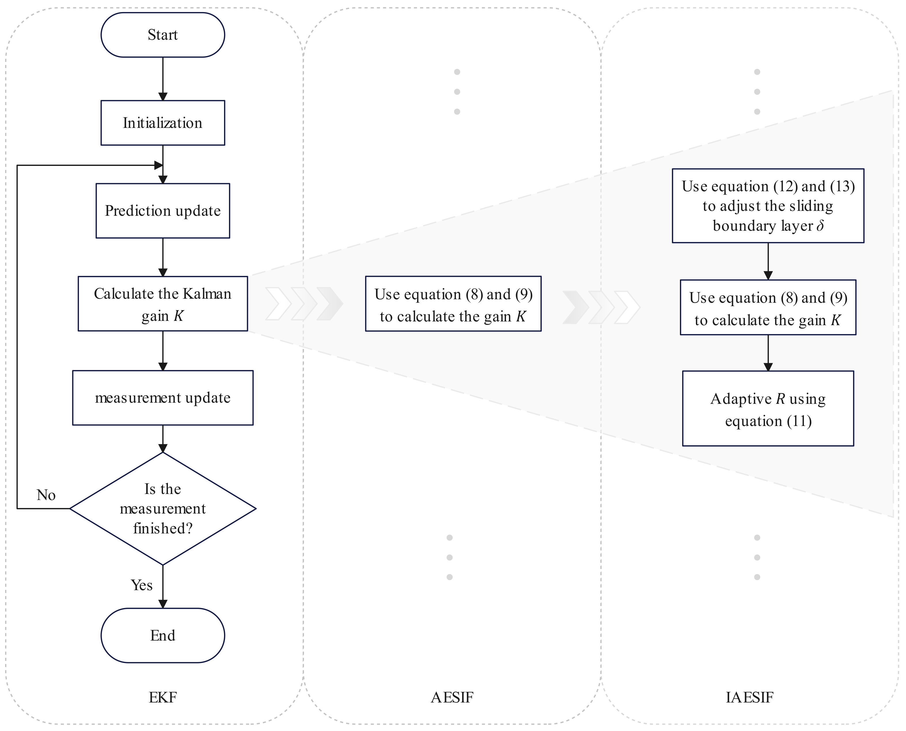
After the detailed introduction of the EKF to the IAESIF above, the general process of the algorithm and its evolution and differences from the EKF to the IAESIF can be summarized, as shown in Figure 2.

4. Verification

4.1. Preliminary

The test data are sourced from public datasets [18]. The main specifications of the battery are detailed in Table 1, and the discharge terminal voltage of the battery at different temperatures can be seen in Figure 3.
Determining the mapping relationship between V o c and SoC is crucial, as shown in Equation (2), and also known as the SoC-OCV curve. The SoC-OCV curve used in this paper was derived through polynomial fitting using the Hybrid Pulse Power Characterization (HPPC) test results at various temperatures. The SoC-OCV curves of the HPPC test results at different temperatures and the polynomial fitting curves are illustrated in Figure 4.
The precise parameters of the circuit equivalent model need to be determined, and data needs to be selected for model parameter identification. Luckily, previous research has already accomplished this task. This article adopts the model parameters provided in the literature [19], as they have been widely validated in prior studies. The remaining parameters used in this paper can be found in Table 2. Additionally, the software and computing environment utilized in this paper are listed in Table 3.
The evaluation metric used is Root Mean Square Error (RMSE), defined by Equation (14):
RMSE = 1 n i = 1 n y i y ^ i 2

4.2. Algorithm Performance

The IAESIF algorithm represents an advancement over the AESIF algorithm by integrating two enhancement strategies: utilizing incremental PID for controlling the sliding boundary layer and incorporating adaptive R. Under the LA92 Dynamometer Driving Schedule (LA92) condition at 25 °C, Table 4 compares the AESIF algorithm and the two enhancement strategies when applied separately. On the other hand, Table 5 displays the outcomes when Gaussian noise with a mean of 0 and a variance of 0.04 is introduced to the terminal voltage. This noise addition simulates the measurement outcomes under conditions of significant noise interference.
From the results, it is evident that the two enhanced strategies exhibit minimal improvement when no noise is introduced. However, a notable improvement is observed after the introduction of noise. This underscores the significant impact of the enhanced strategies in mitigating the effects of noise interference.
The performance evaluation of the IAESIF algorithm, which incorporates the two enhanced strategies, also requires thorough testing. Similarly, taking 25 °C and LA92 as examples, the evaluation metrics RMSE of voltage and SoC estimation errors are shown in Table 6.
From the results, it can be seen that EKF performs the best, while the performance of AESIF and IAESIF algorithms is comparable. This is because, in the case of relatively accurate measurements, the core of the SIF algorithm, which switches around the true state trajectory, does not significantly reduce errors in this situation.
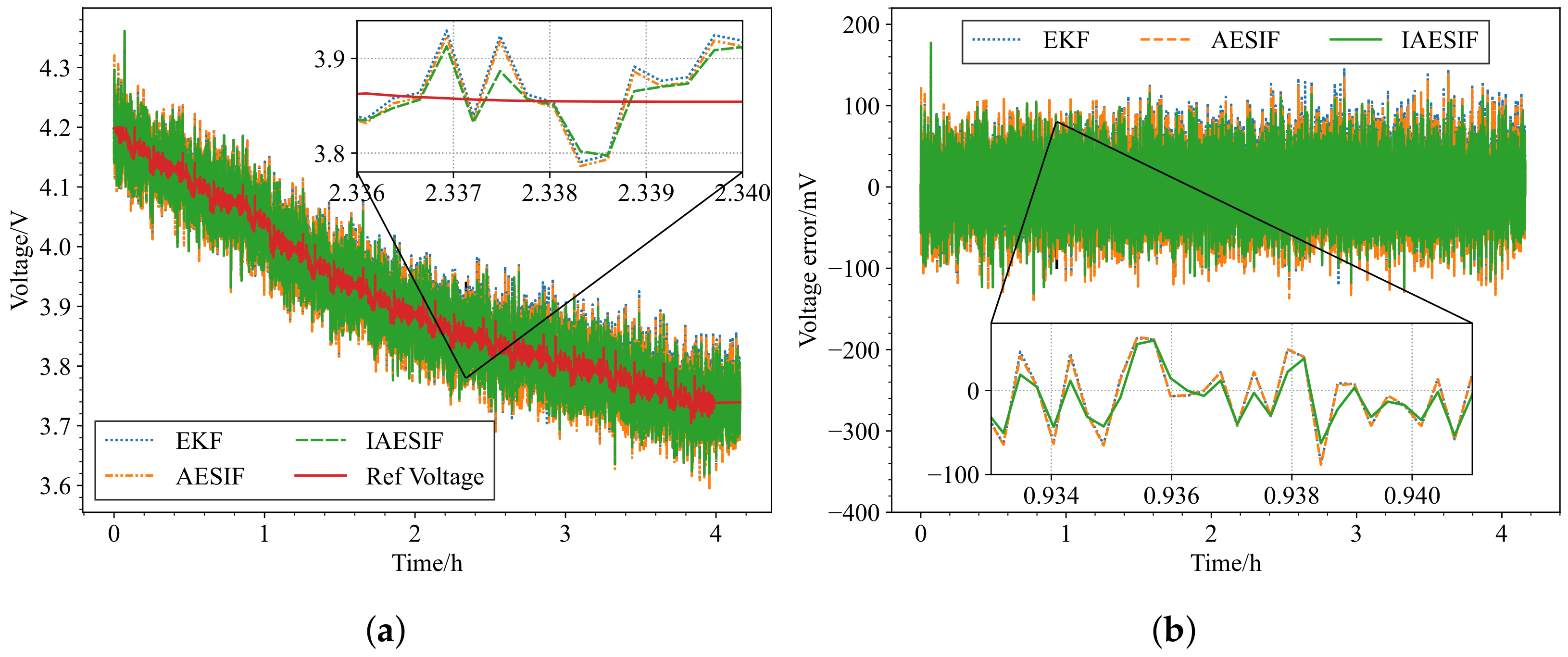
Adding Gaussian noise N ( 0 , 0.04 ) to the terminal voltage, the estimated terminal voltage and SoC results under strong noise conditions are shown in Figure 5a and Figure 6a. The estimation errors are shown in Figure 5b and Figure 6b, and the evaluation metrics RMSE are shown in Table 7.
The results demonstrate a significant improvement compared to the scenario without added noise, particularly in cases where the core of the SIF algorithm switches around the true state trajectory. The algorithm proposed in this paper enhances its performance by adjusting the sliding boundary layer to confine it within a more conservative range, thereby amplifying the benefits of the SIF algorithm. Furthermore, the adaptive parameter R automatically adjusts according to the noise strength, aligning it more closely with the true trajectory. The combination of these two strategies yields more significant improvements than each strategy individually. In contrast, the EKF algorithm lacks the adaptive adjustment of R and the ability to accommodate the trajectory in the presence of strong noise, leading to larger errors when compared to the other two algorithms.

4.3. Testing under Different Working Conditions

It is crucial to assess the algorithm’s effectiveness under various operational circumstances at the same temperature. These assessments are conducted at 25 °C, incorporating different working conditions such as Urban Dynamometer Driving Schedule (UDDS), Highway Fuel Economy Test (HWFET), and US06. Figure 7a,b display the RMSE of voltage and SoC estimation errors under various working conditions without added noise.
The performance of the three algorithms varies, with AESIF and IAESIF algorithms generally not outperforming each other. However, the EKF algorithm performs weaker in predicting SoC compared to the other two algorithms.
Adding N ( 0 , 0.04 ) noise to the terminal voltage, the RMSE bar graphs are shown in Figure 8a,b. Under different working conditions, the IAESIF algorithm is superior to the other two algorithms, with at least a 14% improvement over the AESIF algorithm. However, the EKF algorithm exhibits significant variations in predicting SoC under different working conditions, indicating that the improvement strategies has some applicability under strong noise scenarios.

4.4. Testing under Different Temperatures

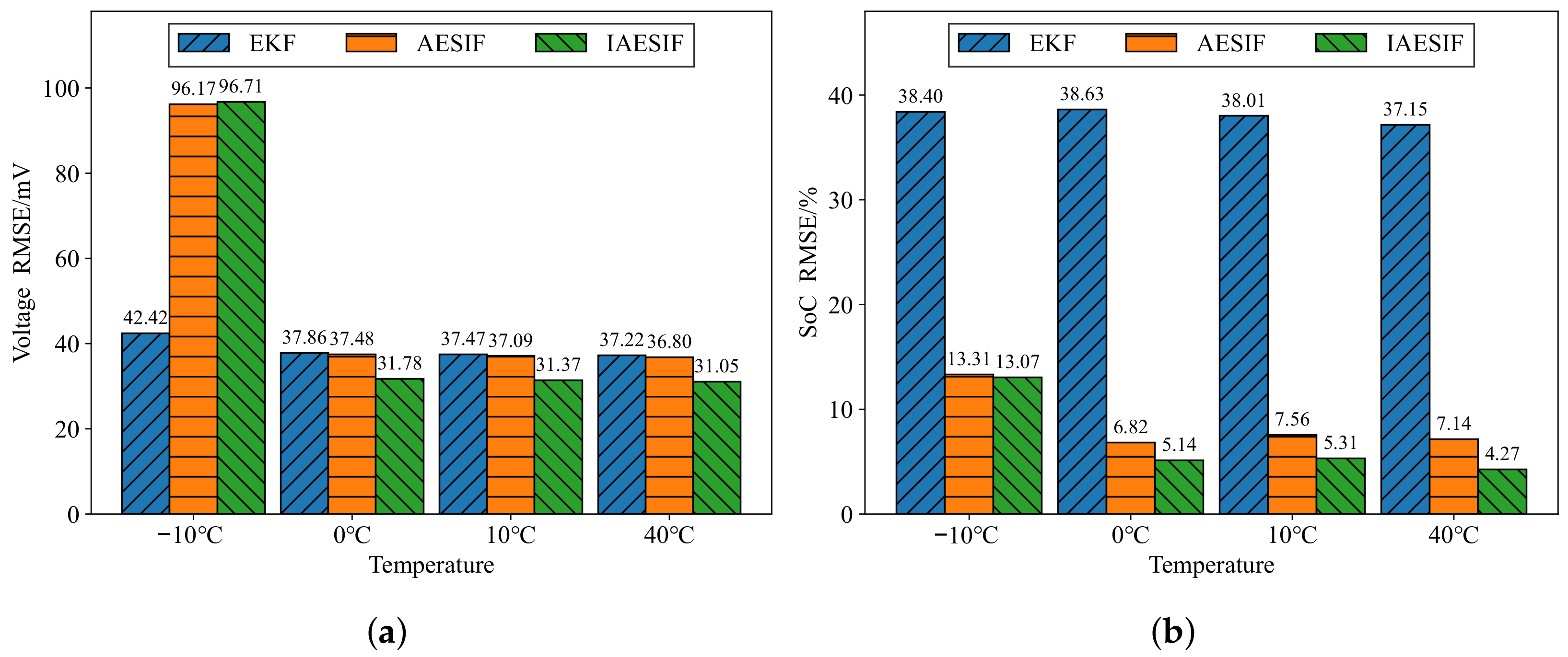
To verify the applicability of the algorithm, testing under different temperatures is also necessary. Taking LA92 as an example, the RMSE of voltage and SoC estimations at different temperatures are shown in Figure 9a,b.
Without added noise, EKF generally performs the best overall, except for the −10 °C scenario, where the performance of AESIF and IAESIF algorithms is comparable. The reason why the error is too large at −10 °C is that there is only one set of initial state parameters for all temperatures, so the lower the temperature, the larger the error [19], coupled with the discharge curve at −10 °C (refer to Figure 3) deviating significantly from the curves at other temperatures, resulting in excessively large errors at −10 °C.
Adding N ( 0 , 0.04 ) noise to the terminal voltage, the RMSE bar graphs are shown in Figure 10a,b.
Similarly, the errors are too significant at −10 °C. At other temperatures, the IAESIF algorithm performs at least 15% better than the AESIF algorithm, and even better than the EKF algorithm. This clearly highlights the effectiveness of the improvement strategy in enhancing estimation accuracy, particularly under challenging noise conditions.

5. Conclusions

This paper mainly improves the AESIF algorithm by adapting to observation noise and utilizing PID control to adjust the sliding boundary layer, proposes an improved version (IAESIF), and combines it with the 2RC equivalent circuit model to estimate the terminal voltage and SoC. The algorithm was tested under varying temperatures and working conditions, with the addition of strong noise. Under the influence of strong noise, compared to the AESIF algorithm, there has been an enhancement of 14% to 40% in the estimation of SoC and terminal voltage across different temperatures (except for the −10 °C scenario) and various working conditions. The improvement, compared to the EKF algorithm, is even more significant. The study suggests that the IAESIF algorithm exhibits a notable improvement in overall estimation accuracy under conditions of strong noise. However, due to limitations in model accuracy and the strategies integrated into the algorithm, there is still room for optimization and improvement.

Author Contributions

Validation, Z.W.; Formal analysis, J.S.; Investigation, Y.X.; Writing—original draft, Z.W.; Writing—review & editing, J.S. and Y.X.; Visualization, Z.W. All authors have read and agreed to the published version of the manuscript.

Funding

We gratefully acknowledge the support of the Jiangsu Provincial Key Research and Development Program (No. BE2022100).

Data Availability Statement

Data are contained within the article.

Acknowledgments

We appreciate the contributions of Phillip J. Kollmeyer, Fauzia Khanum, and others. Without their previous work, we would not have been able to complete the validation work so quickly.

Conflicts of Interest

The authors declare no conflicts of interest.

References

  1. Yue, X.Y.; Yao, Y.X.; Zhang, J.; Li, Z.; Yang, S.Y.; Li, X.L.; Yan, C.; Zhang, Q. The raw mixed conducting interphase affords effective prelithiation in working batteries. Angew. Chem. Int. Ed. 2022, 61, e202205697. [Google Scholar] [CrossRef] [PubMed]
  2. Fang, M.; Yue, X.; Dong, Y.; Chen, Y.; Liang, Z. A temperature-dependent solvating electrolyte for wide-temperature and fast-charging lithium metal batteries. Joule 2024, 8, 91–103. [Google Scholar] [CrossRef]
  3. Hou, J.; Li, T.; Zhou, F.; Zhao, D.; Zhong, Y.; Yao, L.; Zeng, L. A review of critical state joint estimation methods of lithium-ion batteries in electric vehicles. World Electr. Veh. J. 2022, 13, 159. [Google Scholar] [CrossRef]
  4. Yang, F.; Shi, D.; Mao, Q.; Lam, K.H. Scientometric research and critical analysis of battery state-of-charge estimation. J. Energy Storage 2023, 58, 106283. [Google Scholar] [CrossRef]
  5. Rivera-Barrera, J.P.; Muñoz-Galeano, N.; Sarmiento-Maldonado, H.O. SoC estimation for lithium-ion batteries: Review and future challenges. Electronics 2017, 6, 102. [Google Scholar] [CrossRef]
  6. Wang, Z.; Feng, G.; Zhen, D.; Gu, F.; Ball, A. A review on online state of charge and state of health estimation for lithium-ion batteries in electric vehicles. Energy Rep. 2021, 7, 5141–5161. [Google Scholar] [CrossRef]
  7. Bustos, R.; Gadsden, S.A.; Al-Shabi, M.; Mahmud, S. Lithium-Ion Battery Health Estimation Using an Adaptive Dual Interacting Model Algorithm for Electric Vehicles. Appl. Sci. 2023, 13, 1132. [Google Scholar] [CrossRef]
  8. Zhao, F.; Guo, Y.; Chen, B. A Review of Lithium-Ion Battery State of Charge Estimation Methods Based on Machine Learning. World Electr. Veh. J. 2024, 15, 131. [Google Scholar] [CrossRef]
  9. Luo, J.; Peng, J.; He, H. Lithium-ion battery SOC estimation study based on Cubature Kalman filter. Energy Procedia 2019, 158, 3421–3426. [Google Scholar] [CrossRef]
  10. Wang, Y.; Tian, J.; Sun, Z.; Wang, L.; Xu, R.; Li, M.; Chen, Z. A comprehensive review of battery modeling and state estimation approaches for advanced battery management systems. Renew. Sustain. Energy Rev. 2020, 131, 110015. [Google Scholar] [CrossRef]
  11. Zhang, X.; Zhang, W.; Lei, G. A review of li-ion battery equivalent circuit models. Trans. Electr. Electron. Mater. 2016, 17, 311–316. [Google Scholar] [CrossRef]
  12. Gadsden, S.A.; Al-Shabi, M. The sliding innovation filter. IEEE Access 2020, 8, 96129–96138. [Google Scholar] [CrossRef]
  13. Lee, A.S.; Gadsden, S.A.; Al-Shabi, M. An adaptive formulation of the sliding innovation filter. IEEE Signal Process. Lett. 2021, 28, 1295–1299. [Google Scholar] [CrossRef]
  14. Shrivastava, P.; Soon, T.K.; Idris, M.Y.I.B.; Mekhilef, S. Overview of model-based online state-of-charge estimation using Kalman filter family for lithium-ion batteries. Renew. Sustain. Energy Rev. 2019, 113, 109233. [Google Scholar] [CrossRef]
  15. Lee, A.S.; Hilal, W.; Gadsden, S.A.; Al-Shabi, M. Combined Kalman and sliding innovation filtering: An adaptive estimation strategy. Measurement 2023, 218, 113228. [Google Scholar] [CrossRef]
  16. Song, M.; Astroza, R.; Ebrahimian, H.; Moaveni, B.; Papadimitriou, C. Adaptive Kalman filters for nonlinear finite element model updating. Mech. Syst. Signal Process. 2020, 143, 106837. [Google Scholar] [CrossRef]
  17. Akhlaghi, S.; Zhou, N.; Huang, Z. Adaptive adjustment of noise covariance in Kalman filter for dynamic state estimation. In Proceedings of the 2017 IEEE Power & Energy Society General Meeting, Chicago, IL, USA, 16–20 July 2017; IEEE: Piscataway, NJ, USA, 2017; pp. 1–5. [Google Scholar]
  18. Kollmeyer, P. Turnigy Graphene 5000mAh 65C Li-ion Battery Data. Mendeley Data 2020, 1, 10–17632. [Google Scholar] [CrossRef]
  19. Khanum, F.; Louback, E.; Duperly, F.; Jenkins, C.; Kollmeyer, P.J.; Emadi, A. A Kalman filter based battery state of charge estimation MATLAB function. In Proceedings of the 2021 IEEE Transportation Electrification Conference & Expo (ITEC), Chicago, IL, USA, 21–25 June 2021; IEEE: Piscataway, NJ, USA, 2021; pp. 484–489. [Google Scholar]
Figure 1. Equivalent circuit model.
Energies 17 03495 g001
Figure 2. The evolution of the EKF to the IAESIF.
Energies 17 03495 g002
Figure 3. Discharge terminal voltage curve at different temperatures.
Energies 17 03495 g003
Figure 4. SoC to OCV curve.
Energies 17 03495 g004
Figure 5. Terminal voltage estimation result with added noise: (a) terminal voltage change curve and (b) error of terminal voltage estimation.
Energies 17 03495 g005
Figure 6. SoC estimation result with added noise: (a) SoC change curve and (b) error of SoC estimation.
Energies 17 03495 g006
Figure 7. Estimation RMSE under different working conditions: (a) terminal voltage estimation RMSE and (b) SoC estimation RMSE.
Energies 17 03495 g007
Figure 8. Estimation RMSE with added noise under different working conditions: (a) voltage estimation RMSE, and (b) SoC estimation RMSE.
Energies 17 03495 g008
Figure 9. Estimation RMSE at different temperatures: (a) voltage estimation RMSE, and (b) SoC estimation RMSE.
Energies 17 03495 g009
Figure 10. Estimation RMSE with added noise at different temperatures: (a) voltage estimation RMSE and (b) SoC estimation RMSE.
Energies 17 03495 g010
Table 1. Battery main specifications.
SpecificationValue/Description
ChemistryLiPO
Nominal Voltage3.7 V
Charge4.2 V, 50 mA End-Current (CC-CV) Fast
Discharge2.8 V End Voltage, 20 A MAX Continuous Current
Nominal Capacity5 Ah
Energy Density134 (Wh/kg)
Table 2. The remaining parameters used in this paper.
ParameterSymbolValue
Coulomb Efficiency η 0.98
Forgetting Factor α 0.8
Proportional Gain K p 20
Integral Gain K i 0.01
Derivative Gain K d 0
Initial RR 1 × 10 4
Initial PP 0.025 0 0 0 0.01 0 0 0 0.01
Initial QQ 1 × 10 3 0 0 0 1 × 10 3 0 0 0 1 × 10 6
Table 3. Experiment environment.
CategoryDescription
Programming LanguagePython 3.9.13
Libraries and PackagesNumPy 1.25.2, Pandas 2.1.3, SciPy 1.11.4, Matplotlib 3.7.2
Operating SystemWindows 11 22H2
ProcessorIntel(R) Core(TM) i5-10500 CPU @ 3.10 GHz
Memory16 GB DDR4 2533 MHz
Storage512 GB SSD
Table 4. Comparison of the enhancement strategies.
AESIFAESIF-with-PID-Controlled- δ AESIF-with-Adaptive-R
Voltage RMSE (mV)6.9696.9547.036
SoC RMSE (%)0.9590.9590.949
Table 5. Comparison of the enhancement strategies with added noise N ( 0 , 0.04 ) .
AESIFAESIF-with-PID-Controlled- δ AESIF-with-Adaptive-R
Voltage RMSE (mV)37.44036.55934.301
SoC RMSE (%)7.2746.4045.985
Table 6. Algorithm comparison.
EKFAESIFIAESIFImprovement
Voltage RMSE (mV)6.9366.9696.972−0.043%
SoC RMSE (%)0.7700.9590.9560.313%
Table 7. Algorithm comparison with added noise N ( 0 , 0.04 ) .
EKFAESIFIAESIFImprovement
Voltage RMSE (mV)37.74537.44031.70015.331%
SoC RMSE (%)37.3757.2744.35440.143%
Disclaimer/Publisher’s Note: The statements, opinions and data contained in all publications are solely those of the individual author(s) and contributor(s) and not of MDPI and/or the editor(s). MDPI and/or the editor(s) disclaim responsibility for any injury to people or property resulting from any ideas, methods, instructions or products referred to in the content.