Article

Performance Improvement of an MR-Damper-Based Vibration-Reduction System with Energy Harvesting at Sprung Mass Changes

by
Bogdan Sapiński
and
Łukasz Jastrzębski
*
Department of Process Control, Faculty of Mechanical Engineering and Robotics, AGH University of Krakow, Mickiewicza 30 Av., 30-059 Krakow, Poland
*
Author to whom correspondence should be addressed.
Energies 2024, 17(14), 3436; https://doi.org/10.3390/en17143436
Submission received: 30 May 2024 / Revised: 4 July 2024 / Accepted: 9 July 2024 / Published: 12 July 2024
(This article belongs to the Section F: Electrical Engineering)

Abstract

:
The present paper is concerned with a magnetorheological (MR)-damper-based vibration-reduction system with energy harvesting capability considering sprung mass changes. The system represents a mechanical harmonic oscillator with electrical coupling, set in motion by kinematic excitation. The authors examine the system performance in the case when the MR damper control coil (damper control coil) is powered directly by the alternating current resulting from the voltage generated in an electromagnetic harvester in the assumed frequency range of sine excitation. Such a system is able to attenuate vibration in the near-resonance frequency range when the current in the damper control coil increases; however, its drawback is vibration amplification at higher frequencies. To eliminate this negative feature, it is proposed to connect shunt capacitors in parallel with the damper control coil. Then, the system can be tested experimentally in terms of current in the damper control coil, sprung mass, and the capacity of shunt capacitors in order to evaluate system performance according to the assumed performance index. The obtained results demonstrate significant improvement in system performance at higher frequencies of excitation.

1. Introduction

Increasing demand for self-powered technologies in recent years has resulted in the emergence of vibration energy harvesting as one of the promising solutions for power generation [1,2,3,4]. The sources of vibrations affecting mechanical systems may be external factors (e.g., air flow, water waves, seismic vibrations, uneven roads and rails, and other machines operating nearby) or internal factors (e.g., the operating movement of machinery or devices resulting from unbalanced moving elements, assembly errors, abrasive wear or damage of machine elements, or improper dimensional tolerances of cooperating elements). In most cases, the kinetic energy of the vibration occurring in such systems negatively affects the operation and useful life of the system (e.g., impact on hydraulic valves in working machines and vehicles) [5]. This energy, however, can be extracted from vibrating systems and converted into usable electrical energy using harvesters. The harvesters utilize various vibration harvesting techniques, such as electromagnetic, piezoelectric, magnetostrictive, or electrostatic techniques, depending on the power requirements and the range of frequency and amplitude of excitation presented [6,7]. In particular, the harvesters utilizing the electromagnetic energy recovery mechanism are described in [8]. This electric energy can either be stored or used for powering actuators, sensors, and/or control electronics. It should be noted that the harvesters excited by the vibrating systems produce AC power, which is usually processed before use with any device or equipment requiring DC power [9,10,11,12]. To obtain DC voltage, a bipolar Graetz bridge rectifier is usually used, which directly powers the load or a DC–DC voltage converter based on a dedicated integrated circuit or on a microcontroller. A comprehensive review of simultaneous vibration-based energy harvesting and structural vibration control is presented in [13].
The concept of the use the energy recovered from structural vibrations for powering the MR damper in a vibration-reduction system was first proposed with applications in civil engineering by Scruggs and Lindner [14]. From that time, the concept has been developed and a large number of research reports have been published. For example, Cho et al. [15] presented a conceptual design of the electromagnetic harvester in a self-powered, MR-damper-based vibration-reduction system and proposed its application for large-scale civil structures. Hong et al. [16] verified the efficiency of a smart passive system based on an MR damper with an electromagnetic harvester experimentally applying historical earthquakes. Choi et al. [17] demonstrated the feasibility of the MR damper with an electromagnetic energy harvesting mechanism for civil structures and also showed its application for seismic protection of highway bridge structures [18]. Choi and Wereley [19] demonstrated a feasible and efficient self-powered MR damper using a using specially designed spring–mass electromagnetic harvester operating as a dynamic vibration absorber. Wang et al. [20] proposed a self-powered and sensing MR-damper-based vibration-reduction system for seismic protection of elevated bridges. Sapiński [21] presented a math model and experimentally investigated a self-powered and sensing vibration reduction system with a commercial MR damper. The results showed that this system is able to power the MR damper and electromagnetic harvester and can operate as a velocity-sign sensor. In all the above reports, electromagnetic harvesters were used, and due to the applications, research was conducted by excitation in the range up to several Hz. The obtained results revealed that the concept of the MR-damper-based vibration-reduction system with energy harvesting was feasible for the application indicated by Scruggs and Lindner. Returning to the study [21], it was revealed that a vibration reduction system consisting of an MR damper and an electromagnetic harvester was able to power the damper control coil and could adjust itself to structural vibrations. Moreover, the amount of harvested energy was sufficient with regard to the power requirements of each system configuration examined in the study. A detailed analysis of power flows in such a system was carried out in [22].
The present study refers to the concept described above regarding a civil engineering application and also to the concept of energy-regenerative shock absorbers with vibration control and energy harvesting functions, well known in automotive engineering. When compared to the previous authors’ studies, the objective of this paper is to eliminate the drawback of the MR-damper-based vibration-reduction system with energy harvesting in the case of sprung mass changes (i.e., vibration amplification at higher frequencies). To achieve this, it is proposed to connect shunt capacitors in parallel with the damper control coil, which should improve the operation of the system at higher frequencies of excitation. It is worthwhile to mention that knowledge about the behaviour of the considered MR-damper-based vibration-reduction systems in the context of the sprung mass changes is slight; however, the authors believe that dual-function devices have potential and are promising in applications to civil engineering, automotive engineering, and mechanical structures.
The paper is structured as follows. Section 1 refers to the results of scientific reports in the scope of the system investigated in the study and recalls the authors’ former achievement in this regard. In Section 2, the authors commence the study by characterizing the system structure. Section 3 outlines the approach to the considered problem. Section 4 describes the key details of the experimental set-up and illustrates the testing procedure to evaluate the performance of the system in terms of the current in the damper control coil, sprung mass changes, and capacity of the shunt capacitor. This Section is complemented by a discussion of the study’s outcome. A summary is provided in Section 5.

2. Structure of the System

A schematic diagram of the system under consideration is shown in Figure 1a. The MR-damper-based vibration-reduction system and sprung mass create a damped harmonic oscillator with one degree of freedom. As can be seen, from one side, the MR damper [23], harvester, and spring are attached to the sprung mass; from the other side, they are attached to a shaker plate, which affects the system via kinematic excitation. Change in the relative damping ζ of the harmonic oscillator occurs due to a change in the current level in the damper control coil, while change in the sprung mass results from the addition to the primary mass of an additional mass (from one to four plates). The frequency of the free vibration f 0   and the resonance frequency f r of the harmonic oscillator are shown by the formulas f 0 = 1 / 2 π k / m and f r = f 0 1 2 ζ 2 , where m is sprung mass, k is the stiffness coefficient of the spring, and ζ is the viscous damping factor. The relationship between the vibration amplitude of the sprung mass (displacement x) and the excitation amplitude (shaker displacement z) at the resonance frequency determines the quality factor of the system, shown by the formula Q = 1 / ζ [24].
Upon setting the system into a vibrating state, it is possible to convert part of the kinetic energy of the sprung mass into electrical energy using an electromagnetic harvester, which operates according to Faraday’s law of electromagnetic induction. The energy harvested can be used to power the damper control coil with the voltage generated in the harvester coil uh, as illustrated in Figure 1b. When the winding of the damper control coil (represented by resistance Rd and inductance Ld) is combined with the winding of the harvester coil (represented by the generated electromotive force e, resistance Rh, and inductance Lh), an alternating current flows in the circuit. Then, the system operates in harvesting mode.

3. Outline of the Approach

Characteristics of the transmissibility coefficient of the considered MR-damper-based vibration-reduction system are shown by the formula Txz(f) = xrms(f)/zrms(f), where xrms and zrms are the rms value of the sprung mass displacement and of the shaker displacement, respectively. The exemplary plots Txz(f) with sprung mass m = const and at two DC current levels, Id2 and Id1, in the damper control coil are shown in Figure 2. In this figure, two zones have been distinguished, Zone I and Zone II. It can be clearly seen that in Zone I, the vibration amplitude of the sprung mass takes higher values than the amplitude of the shaker (vibration amplification zone), whereas in Zone II, the vibration amplitude of the sprung mass takes lower values than the amplitude of the shaker (vibration attenuation zone). Note that frequency f c = 2 f 0 ,   Txz = 1. The increase in relative damping ζ resulting from the increase in the DC current level in the damper control coil Id (Id2 > Id1) causes a decrease in the vibration amplitude of the sprung mass in the frequency range (0, f c ) and an increase in the amplitude at frequencies higher than f c , which is a characteristic trait of harmonic oscillators using kinematic excitation.
However, in Zone II, it is evident that at frequencies higher than f c , the transmissibility coefficient Txz takes higher values at current level Id2 than at Id2. This is the drawback of the MR-damper-based vibration-reduction system with energy harvesting when the damper control coil is powered by an alternating current resulting from the voltage generated at the harvester output. A similar situation occurs when the system operates in energy harvesting mode (powering the alternating current). To eliminate this drawback, it is proposed to connect a shunt capacitor with capacitance C in parallel with the damper control coil (Figure 1b). Then, at a frequency of excitation higher than f c , a higher current ic flows in the shunt capacitor. This makes the lower current ic flow in the damper control coil and prevents an increase in the transmissibility coefficient Txz. The maximum capacity of the shunt capacitor is limited to the maximal output current in the harvester ih, which depends on both the load impedance (impedance of the connected shunt capacitor in parallel with the damper control coil) and output voltage of the harvester uh, which corresponds to a relative velocity x ˙ z ˙ . When selecting the maximum capacity of the shunt capacitor, it was assumed that the maximal output current of the harvester ih takes place at maximal frequency f of excitation z. In this case, the impedance of the shunt capacitor is the lowest, and the output voltage of the harvester uh is the highest.
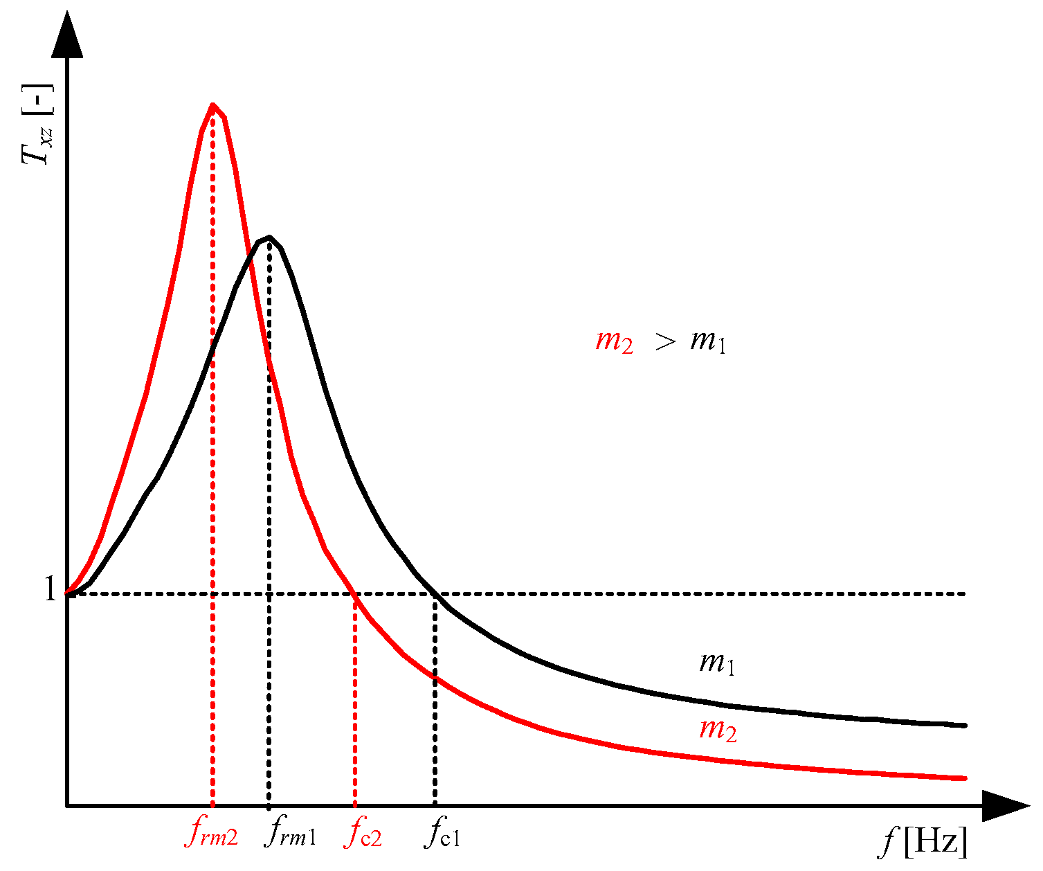
Figure 3 compares the exemplary plots Txz(f) at currents in the damper control coil Id = 0 and at two sprung masses, m2 being greater than m1. It can be clearly seen that with a change in sprung mass, there are changes in frequencies f r and f c and the value of the Q factor.

4. Testing Procedure and Performance Evaluation of the System

The aim of the tests was to evaluate the performance of the system when:
  • The control coil was powered from an external power source by a constant current with various levels or alternating current from the harvester, assuming constant sprung mass;
  • The control coil was not powered or powered by alternating current from the harvester, considering assumed sprung mass changes;
  • The control coil was connected in parallel with shunt capacitors and powered by alternating current from the harvester and constant sprung mass.
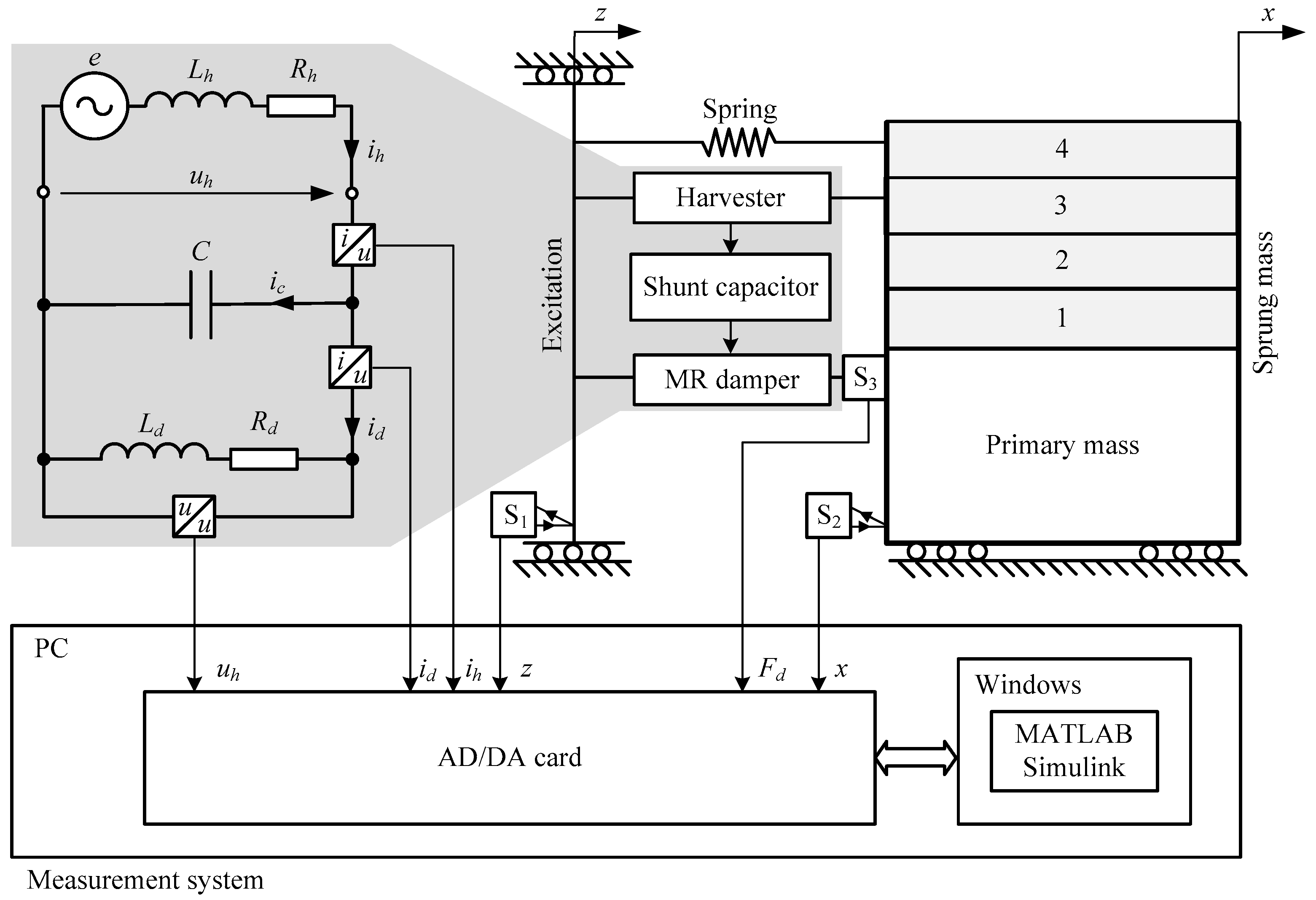
The system was tested in the experimental set-up, which is shown in the diagram in Figure 4. The set-up incorporates the following: a Bruel & Kjaer LDS V780 electrodynamic shaker [25] with Bruel & Kjaer HPA-K amplifier [26], a measurement system and mechanical harmonic oscillator with electrical coupling resulting from connecting the harvester coil, and a damper control coil. The oscillator is composed of a sprung mass (primary mass and additional mass changed every 25 kg from 100 kg to 200 kg), an RD-8040-1 MR damper by Lord Co. [27], a spring connected in parallel with the stiffness coefficient of k = 105 N/m, and an electromagnetic harvester whose concept was described [28] and structure in [29]. The measurement system allows the following quantities to be obtained: shaker displacement z and sprung mass displacement x using a Sensopart FT50RLA70 Sensor S1 and Sensor S2 [30], damper force Fd using an EMS30-5kN Sensor S3 [31], harvester output voltage uh, current in the harvester coil ih, and current in the damper control coil id. The measured quantities were converted into voltage signals ±10 V and sampled with a frequency of 1 kHz using an AD/DA card [32] supported by MATLAB/Simulink 2020a software.
In the testing procedure, the shaker produced a kinematic sine excitation with a constant frequency, which set the oscillator in motion. Movements at certain frequencies always lasted 30 s. In the first 10 s, the excitation amplitude was increased, causing a gradual increase in the displacement amplitude of the sprung mass. For a further 10 s, the amplitude of excitation was maintained at a stable value of 3.5 mm. During this time, the following quantities were recorded: displacement z, displacement x, voltage uh, current ih, current id, and force Fd. Over the next 10 s, the amplitude of excitation was gradually decreased until the oscillator stopped moving.
The tests were conducted at frequencies of sine excitation in the range (2, 10) Hz with a step of 0.1 Hz. Based on the recorded time patterns, the following were calculated: the characteristics of the transmissibility coefficient Txz(f) and the rms characteristics of the electromotive force E(f), harvester output voltage Uh(f), harvester current Ih(f), current in the damper control coil Id(f), and damper force Fd(f).
Regarding the frequency range of excitation (2, 10) Hz in which the tests were carried out and the frequency fc that separates Zone I (vibration amplification) and Zone II (vibration attenuation), the following performance indexes of J1, J2, and J3 (Equations (1)–(3)) were introduced to evaluate the performance of the considered system:
J 1 = 1 f 2 f 10 f 2 f 10 T x z f d f ,
J 2 = 1 f 2 f c f 2 f c T x z f d f ,
J 3 = 1 f c f 10 f c f 10 T x z f d f .

4.1. Impact of Current in the Damper Control Coil

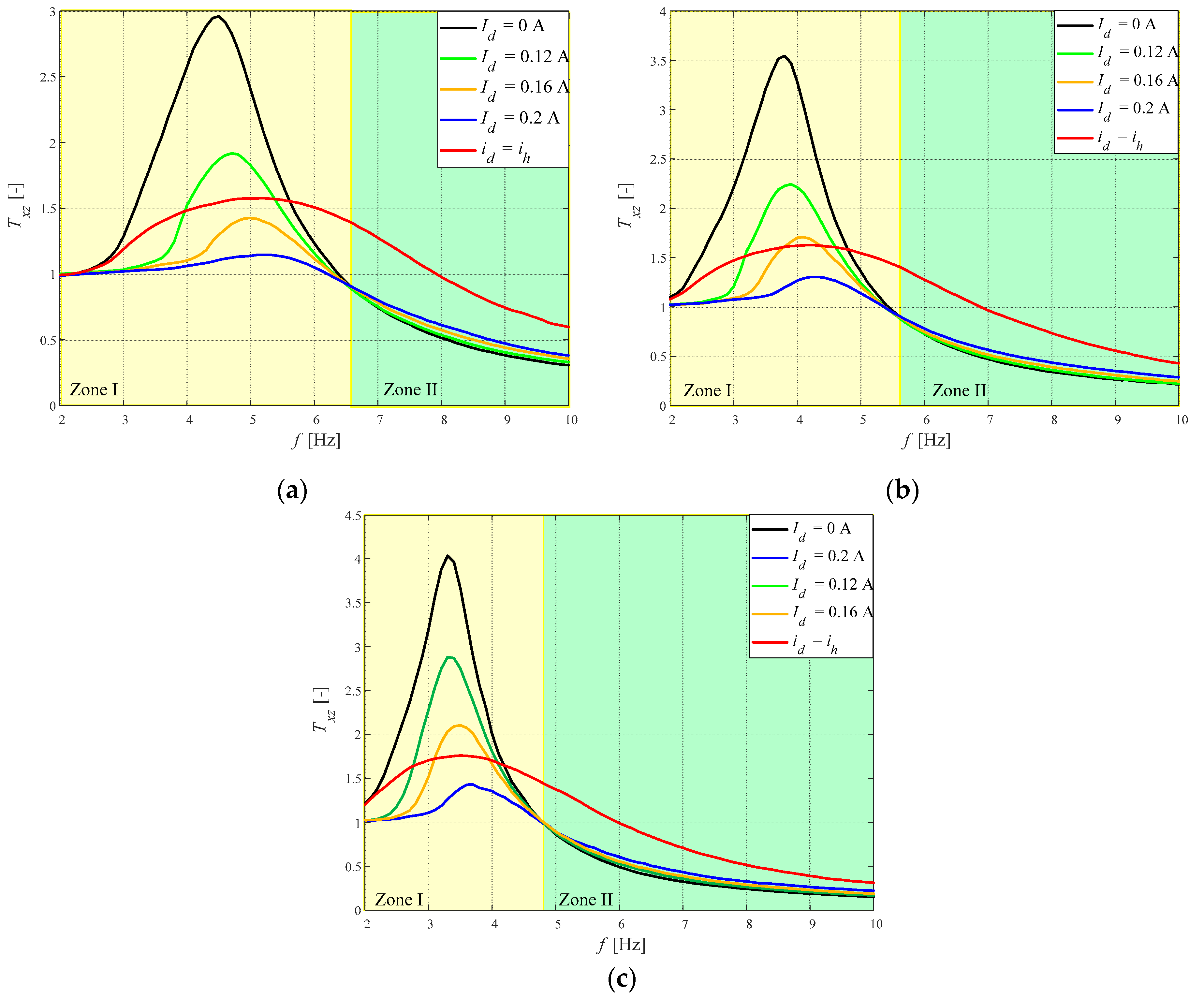
When assessing the performance of the system, the frequency characteristics of the transmissibility coefficient Txz(f) were used. Figure 5a–c shows exemplary Txz(f) graphs for sprung masses of 100, 150, and 200 kg, respectively, in the cases when the control coil was not powered (Id = 0 A), was powered by a constant current Id of 0.12, 0.16, or 0.2 A, and by alternating current id = ih. As it can be seen, each of these characteristics reaches its maximum at resonance frequency fr. The value Txz(fr) defines the so-called system quality factor Q. The values of resonance frequencies fr, system quality factor Q, quality criteria J1, J2, and J3, and damping coefficient ζ for the sprung mass values given above are summarized in Table 1, Table 2 and Table 3.
An analysis of the graphs in Figure 5 shows that the increase in current in the damper control coil Id causes a decrease in the system quality factor Q, as well as a decrease in the vibration amplitude of the sprung mass in Zone I, while causing an increase in Zone II. This is a characteristic trait of harmonic oscillation with kinematic excitation, when the vibrations are transmitted from the shaker to the sprung mass via a spring and damper fitted in parallel. Frequency fc, at which the coefficient Txz is constant and independent of the current level Id, is the frequency that separates Zone I from Zone II (Figure 2). It should be noted here that frequency fc is dependent on the sprung mass. At sprung masses of 100, 150, and 200 kg, the value of fc is 6.6, 5.6, and 4.7 Hz, respectively. Additionally, it can be seen that frequency fr increases along with an increase in current Id. This occurs because the damper force Fd, which is dependent on current Id, impacts both the viscous damping factor ζ and the total stiffness coefficient of the oscillator.
When the damper control coil is powered by the harvester output voltage uh, the vibration amplitude of the sprung mass decreases in the vicinity of the frequency fr. A comparison of the obtained values for system quality factor Q with those obtained at Id = 0 A shows that the vibration amplitude of the sprung mass decreases 1.9-fold, 2.2-fold, and 2.3-fold, respectively, at sprung masses of 100, 150, and 200 kg. However, it can be seen that higher values of the transmissibility coefficient Txz(f) occur as early as at frequencies of 5.7, 4.8, and 4.2 Hz, respectively; nonetheless, they are lower than frequency fc. This is also confirmed by the values of the J2 and J3. Moreover, the value of J1 shows that in the frequency range (2, 10) Hz, the sprung mass vibration decreases slightly (about 4%). It should be stressed that J3 shows the highest value when the damper control coil is powered by an alternating current from the harvester. This unfavourable trait of the system results from excessive current in the damper control coil id harvested at frequencies higher than fc. To eliminate this drawback, it is proposed to connect shunt capacitors in parallel with the damper control coil.

4.2. Impact of Sprung Mass

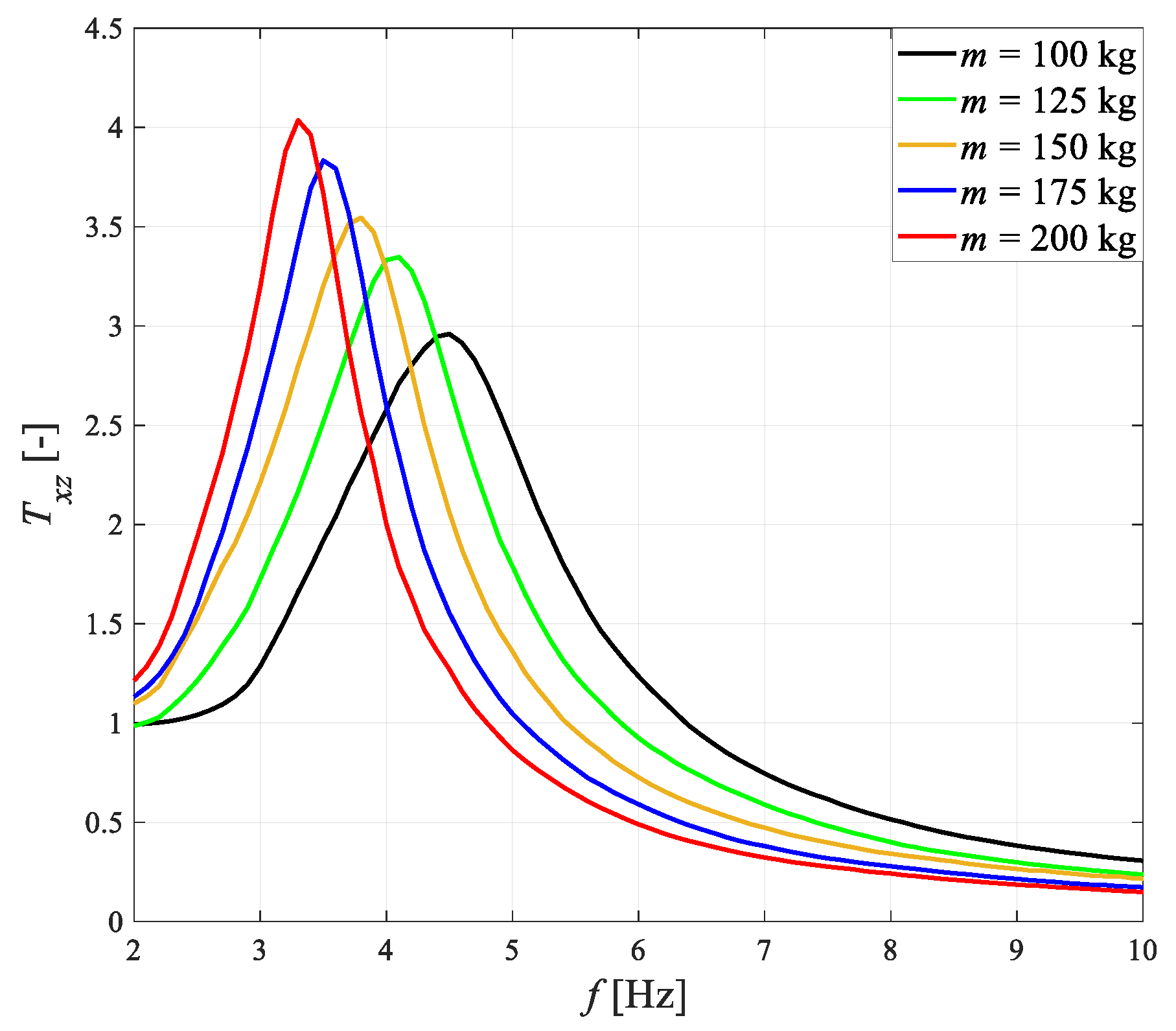
To analyze impact of the sprung mass changes on system performance, two cases were considered, i.e., when the damper control coil was not powered or powered by alternating current id. In both cases, the following frequency characteristics were used: transmissibility coefficient Txz(f), electromotive force E(f) or harvester output voltage Uh(f), current Id (f), and damper force Fd(f). It was assumed that the sprung mass would be changed as follows: 100, 125, 150, 175, and 200 kg.
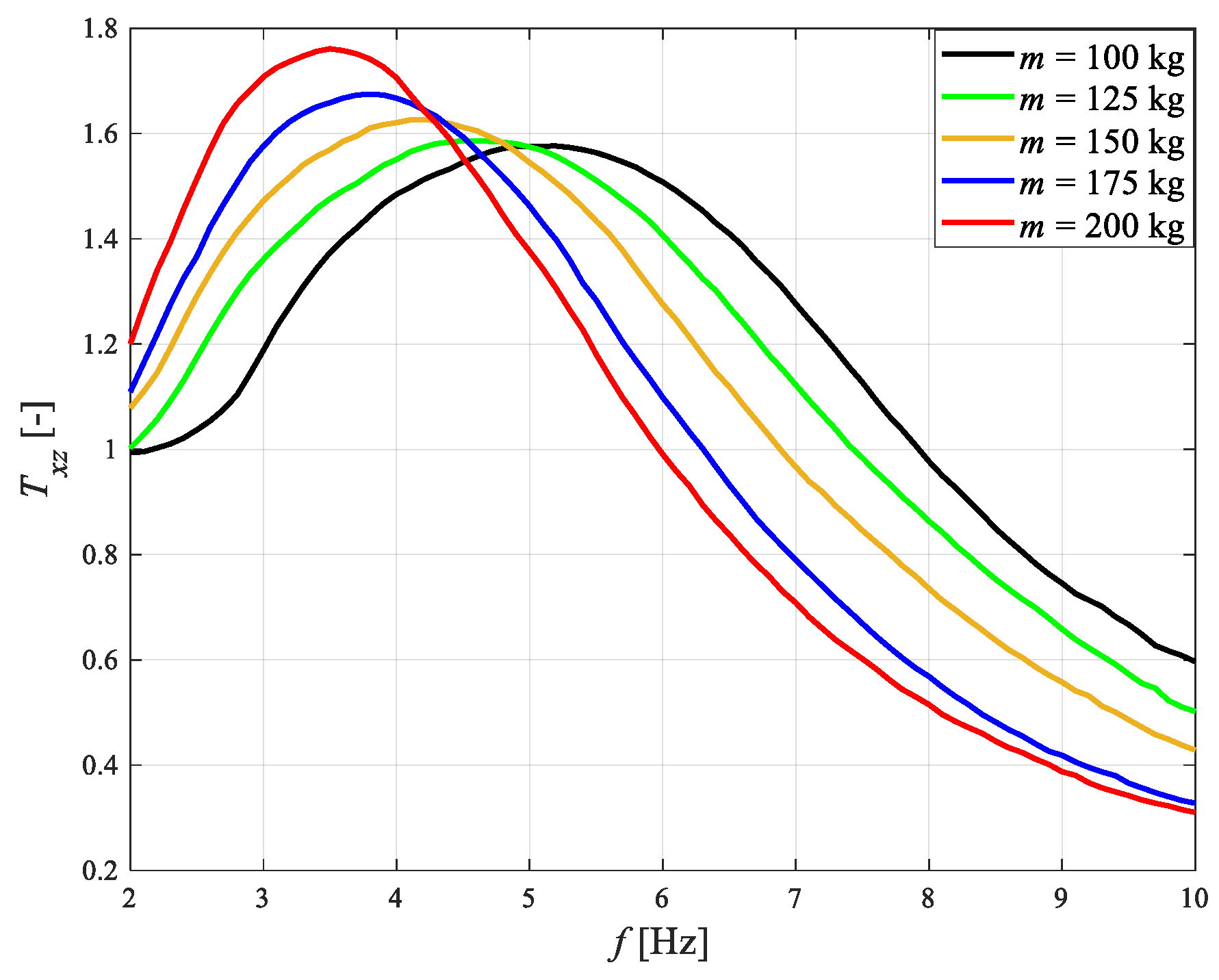
The frequency characteristics of Txz(f) are presented in Figure 6. It can be seen that the increase in the sprung mass causes an increase in the system quality factor Q and a decrease in frequency fr, which is associated with changes in the free vibration frequency of the system f 0 .
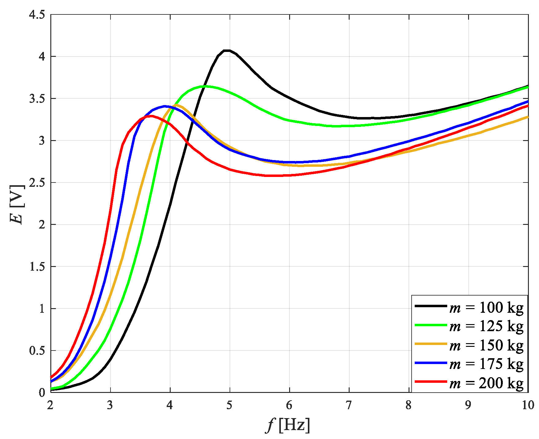
Figure 7 shows the frequency characteristics of the rms of the electromotive force E(f). The maximum visible in each graph occurs at a frequency slightly higher than frequency fr, which decreases along with the increase in sprung mass. At frequencies higher than 7 Hz, the value of E increases along with frequency f, independently of sprung mass.
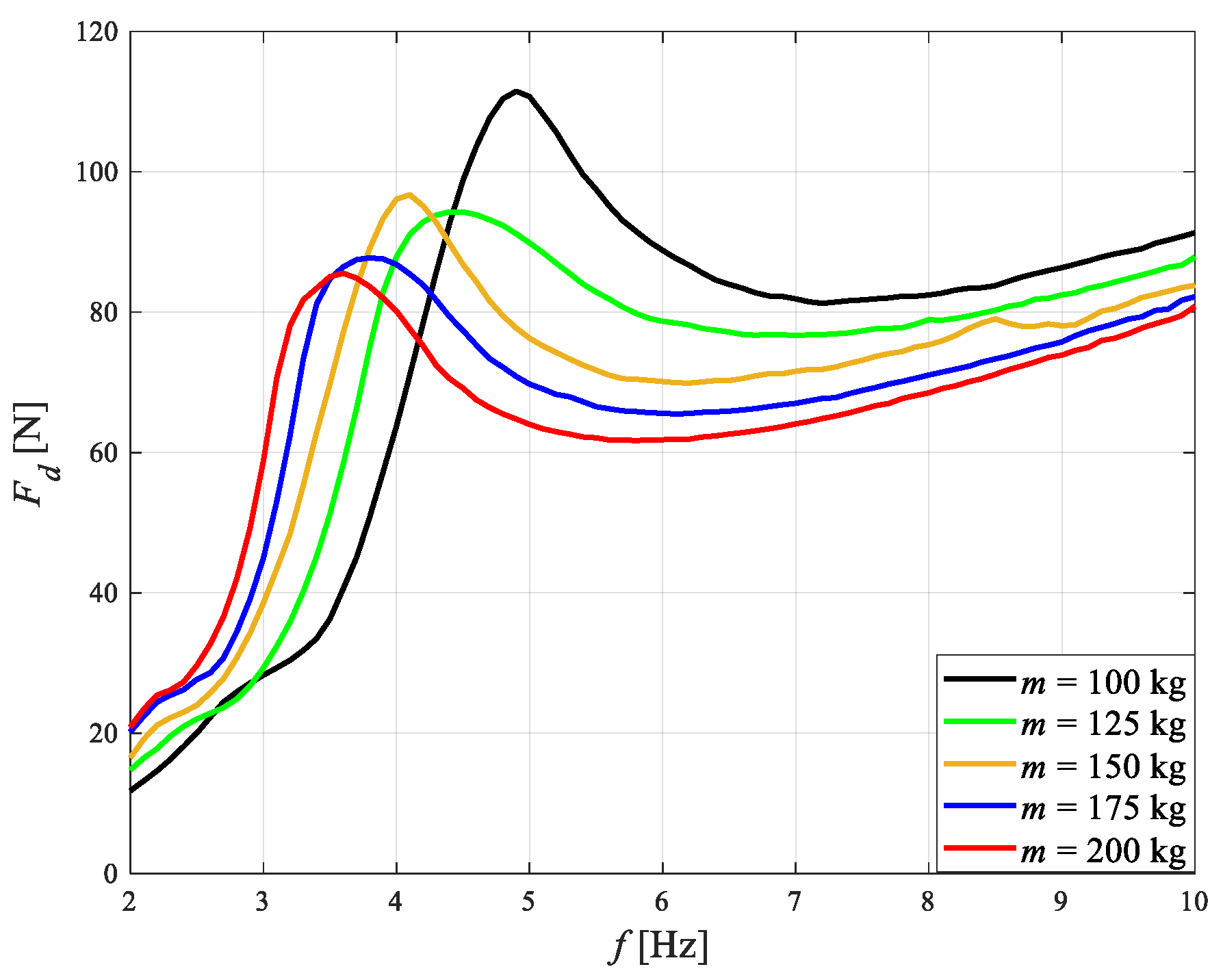
The frequency characteristics of the rms of damper force Fd(f) are revealed in Figure 8. It can be seen that the shape of the graphs is similar to the graphs from Figure 7. This similarity results from the fact that in this case Id = 0; thus, damper force Fd depends solely on the relative velocity x ˙ z ˙ .
In the case where the damper control coil is powered by alternating current id and the sprung mass is changed, frequency fr also decreases, which is shown in Figure 9. As it can be seen, a two-fold increase in sprung mass causes a 12% increase in quality factor Q. A comparison of the graphs from Figure 9 with those from Figure 6 shows that at Id = 0, a two-fold increase in mass causes a 37% increase in system quality factor. This is due to the fact that in the vicinity of frequency fr, damping of vibrations increases along with the increase in sprung mass.
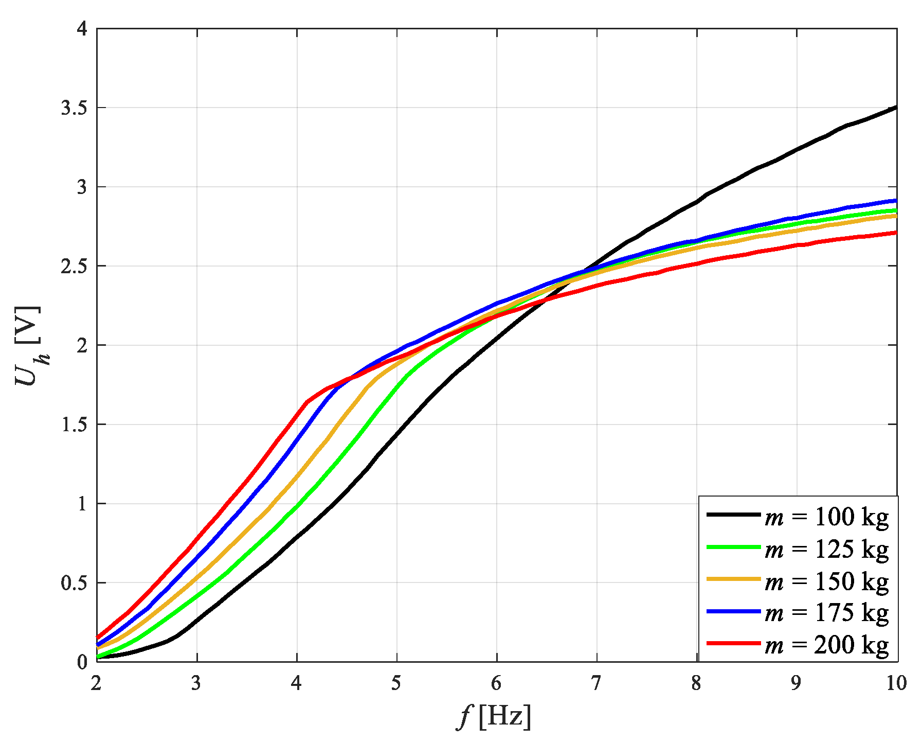
Figure 10 reveals the frequency characteristics of the rms of voltage Uh(f). It is evident that voltage Uh increases along with an increase in frequency, yet the velocity of increase in the voltage decreases at frequencies higher than fr. In contrast to the graphs for E(f) (Figure 7), in the graphs for Uh(f), maxima do not occur.
The frequency characteristics of the rms of current in the damper control coil Id(f) are shown in Figure 11. Current Id increases along with an increase in frequency at frequencies lower than fr, while at frequencies higher than fr, current Id achieves comparable values. The exception here is the system with a sprung mass of 100 kg, in which current Id increases in the whole assumed frequency range of excitation. The reason for the absence of an increase in current Id, despite the increase in voltage Uh (Figure 10), is the increase in impedance of the serially joined harvester coil and damper control coil.
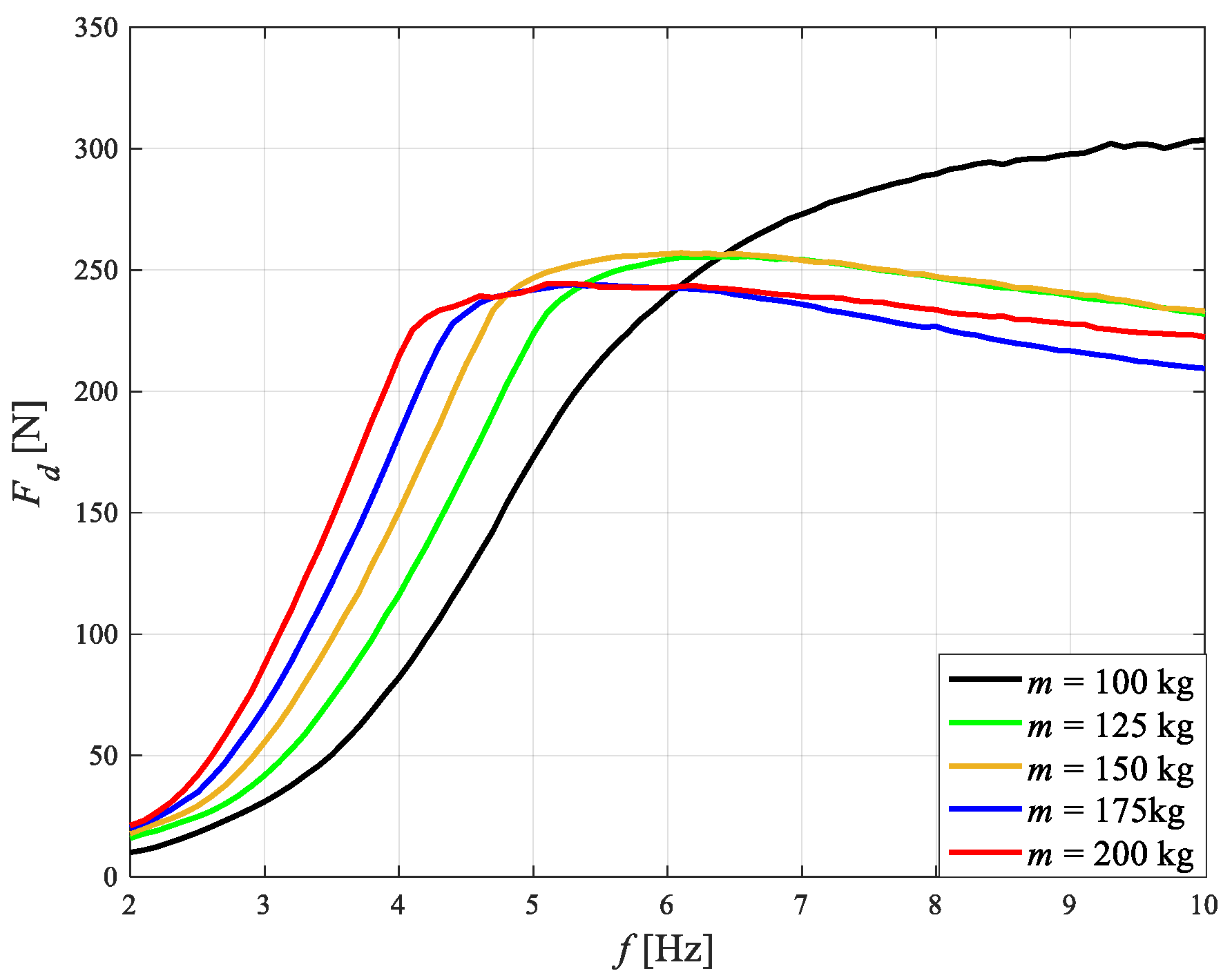
Figure 12 presents the frequency characteristics of the rms of damper force Fd(f). As it can be seen, damper force Fd increases along with an increase in frequency at frequencies lower than fr. In turn, at frequencies higher than fr, a decrease in damper force occurs along with frequency. In this case, the exception is the system with a sprung mass of 100 kg. This particular shape of the characteristics Fd(f) results from the fact that it is dependent both on current Id and on relative velocity x ˙ z ˙ .

4.3. Impact of Shunt Capacitors Capacity

To reduce the vibration amplitude of the sprung mass in Zone I and Zone II, the damper control coil is connected in parallel with shunt capacitors and powered by alternating current ih, while considering assumed sprung mass changes (Figure 1b). The connected-in-parallel shunt capacitors comprise an additional branch in the circuit, which current ih flows through. The increase in the frequency of voltage uh causes a decrease in the capacitive reactance of the shunt capacitors and simultaneously an increase in the reactance of the damper control coil. This makes the lower current id flow in the control coil and prevents an increase in damper force Fd and, thus, of the transmissibility coefficient Txz. Therefore, the function of the applied shunt capacitors is to cut off the current to the damper control coil at higher frequencies.
The graphs from Figure 5, which illustrate the impact of current Id on the frequency characteristics of Txz(f) show that at an excitation with a frequency higher than fc (dependent on f0 and, thus, also on m), the current Id should be significantly limited. To determine the impact of the shunt capacitors on system performance (vibration damping of the of sprung mass), bipolar electrolytic capacitors were used in the tests; these joined in parallel made it possible to obtain the following capacities: 9.4, 18.8, 28.2, and 37.6 mF. The test results in Figure 13 show that the higher the capacity of the shunt capacitors, the greater the damping of vibrations. This is confirmed by the performance index values provided in Table 4, Table 5 and Table 6. In the case where the sprung mass was 100 kg, an increase in capacity caused a decrease in system quality factor Q, with the exception of the highest capacity of 37.6 mF, at which there was a slight increase. In the case of the sprung masses of 150 and 200 kg, an increase in capacity caused a slight increase in quality factor Q. It should be noted that regardless of the value of the sprung mass, a capacity of 9.4 mF is insufficient to cause a meaningful increase in the vibration damping of the sprung mass when compared to the case in which there are not shunt capacitors in the circuit.
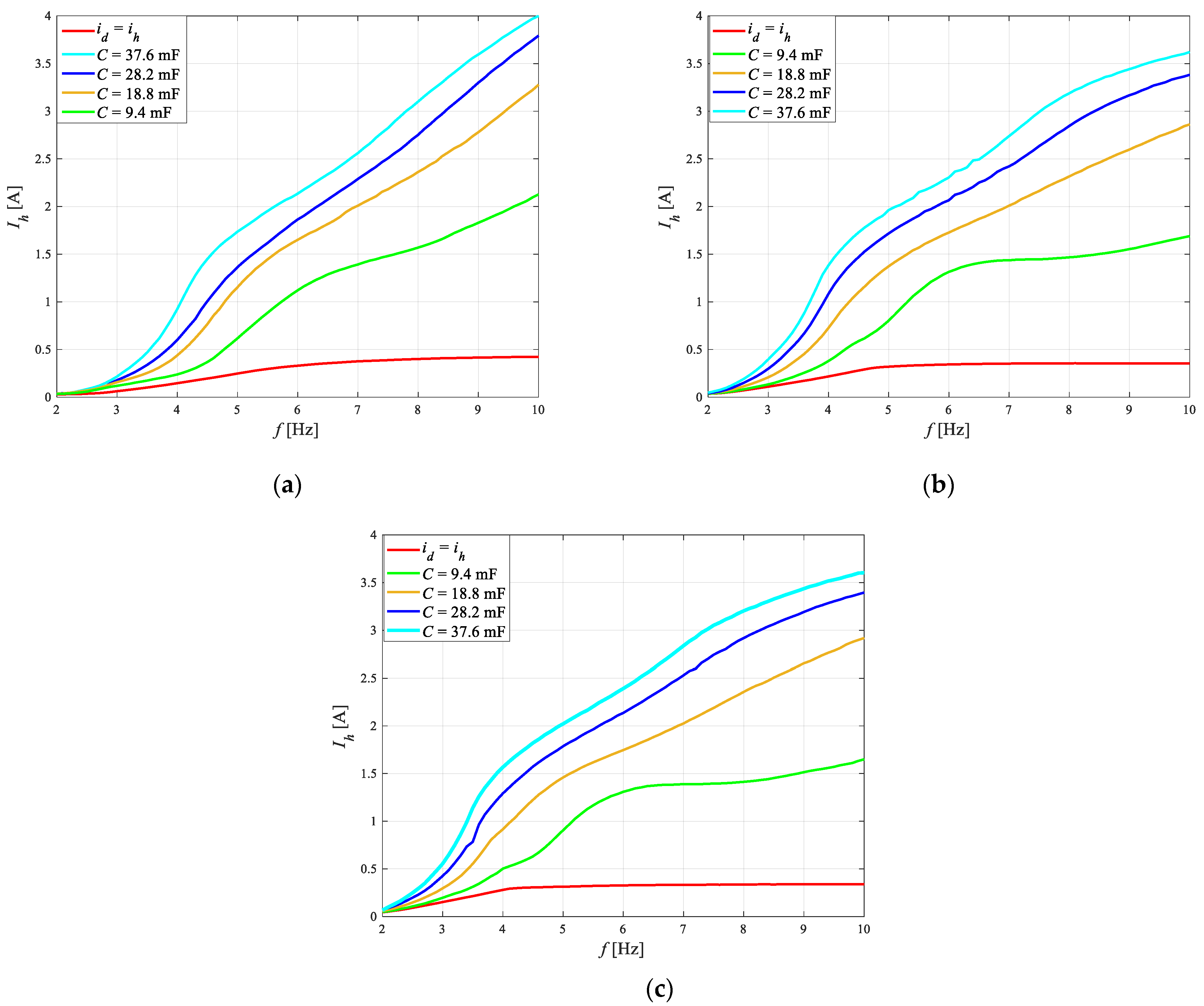
The maximum capacity of the shunt capacitors is limited by the effective value of the current drawn from the harvester Ih. The frequency characteristics of the rms of the current Ih(f) are shown in Figure 14. As it can be seen, an increase in the capacity of the shunt capacitors causes an increase in current Ih, due to their decrease in capacitive reactance and the subsequent increase in current ic. As an example, at a sprung mass of 100 kg and an excitation frequency of 10 Hz, current Ih takes the value of 4 A. An increase in the sprung mass causes a slight decrease in current Ih, which may be related to the lower vibration amplitudes of the sprung mass at higher frequencies of excitation (see performance index J3 in Table 4, Table 5 and Table 6).
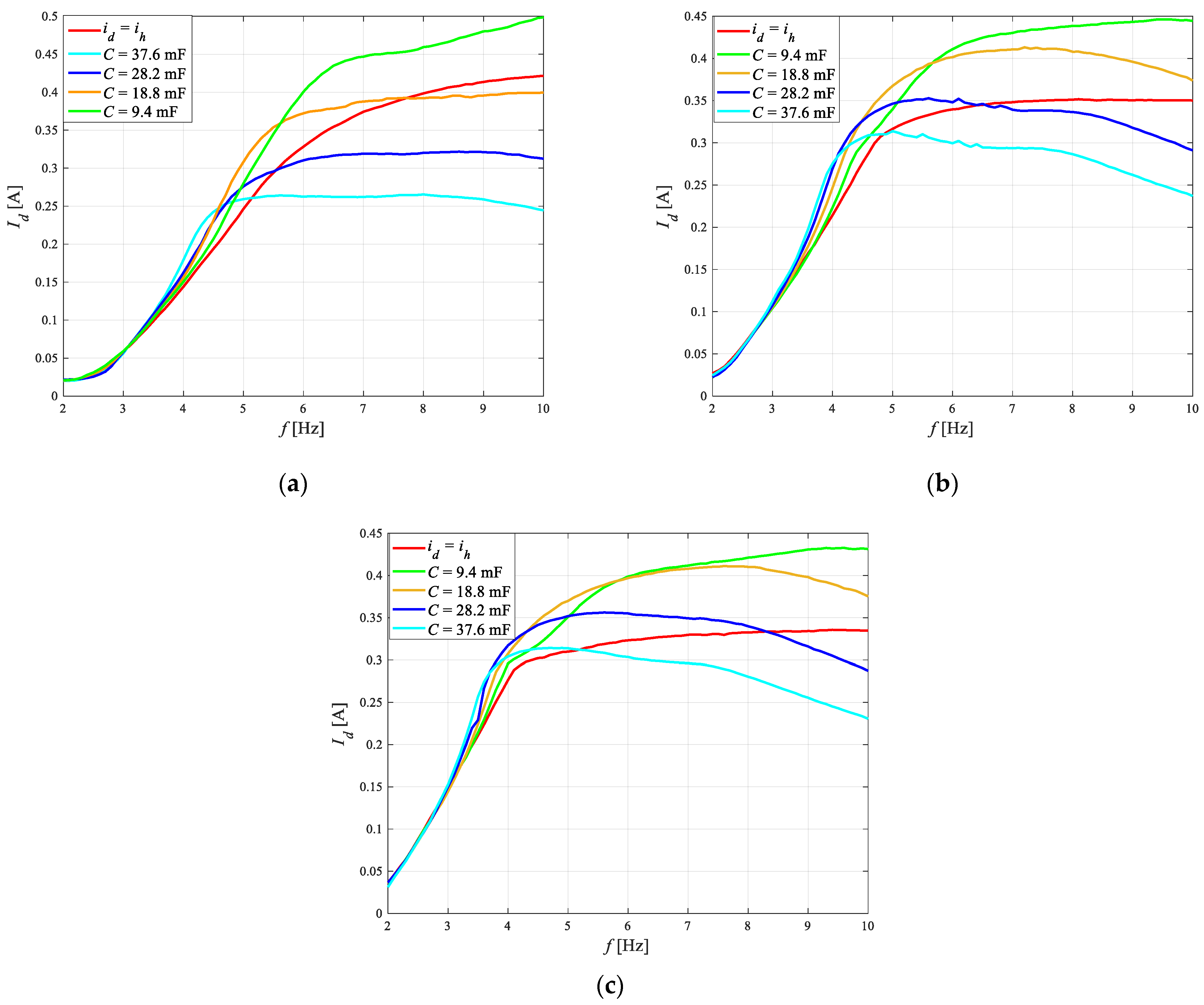
Figure 15 shows the frequency characteristics of the rms of the current in the control coil Id(f). When the control coil is powered directly from the harvester, current Id increases along with f, while the velocity of these changes decreases at frequencies higher than fr. This effect of a decrease in the velocity relative to an increase in current results mainly from the increase in the impedance of the control coil. The addition of shunt capacitors to the circuit does not significantly impact the change in current Id in a range of frequencies lower than 3.5 Hz and is not dependent on sprung mass. This is caused by the high equivalent impedance of the capacitors (then idih). At higher frequencies, current Id starts to become limited as the equivalent impedance of the shunt capacitors decreases. As it can be seen, at frequencies higher than 3.5 Hz, the higher the capacity of the shunt capacitors, the lower is the current Id. Additionally, it can be seen that shunt capacitors of 9.4 mF capacity are insufficient and that an increase in current Id occurs when compared to direct powering damper control coil from the harvester (idih). It can also be seen that an increase in the sprung mass requires the use of shunt capacitors of higher capacity in order to decrease current Id in comparison to the system that does not feature shunt capacitors.
Figure 16 presents the frequency characteristics of the rms of the damper force Fd(f). It can be seen from the graphs that at frequencies lower than fr, force Fd increases rapidly, which is associated with the rapid increase in current Id. The exception is the frequency range of (2, 2.5) Hz, at which the damper force Fd has similar values regardless of the configuration of the circuit from Figure 1a. This is caused by the low relative velocity x ˙ z ˙ . Each of the graphs for Fd(f), showing sprung masses of 100, 150, and 200 kg, has a clear maximum, at frequencies of 8.8, 6.3, and 5 Hz, respectively. At higher frequencies, damper force Fd decreases, despite the slow increase in current Id (Figure 15).
When shunt capacitors are introduced into the circuit, at least one local maximum occurs at frequencies higher than the resonance frequency and a local minimum occurs in the frequency characteristics of the damper force Fd. At higher frequencies, the introduction of shunt capacitors causes a decrease in damper force Fd, in comparison to the case in which Id = 0 A. This explains the effect of the decrease in the transmissibility coefficient Txz (f) (Figure 13). However, it is interesting that for the shunt capacitors of the lowest capacity, despite a higher current Id (Figure 15), damper force Fd achieves the lowest values (Figure 16).

5. Summary and Conclusions

This paper is concerned with the MR-damper-based vibration-reduction system with energy harvesting considering sprung mass changes. Assuming that the damper is powered by alternating current produced by an electromagnetic harvester, the authors demonstrate how the system’s performance can be improved by connecting shunt capacitors of appropriate capacity in parallel with the damper control coil. To confirm that, they evaluate system performance under an experimental procedure in terms of current in the damper control coil, sprung mass, and the capacity of shunt capacitors using proposed performance indexes.
The tests results lead the authors to the following conclusions.
  • An increase in current level Id results in a decrease in the sprung mass vibration amplitude in the range (2, fc) Hz (Zone I) and an increase in the range (fc, 10) Hz (Zone II).
  • An increase in current level Id also results in a decrease in quality factor Q and the performance indexes J1 and J2; this is in contrast to the performance index J3, which takes higher values.
  • Supplying the damper control coil by alternating voltage (produced by the harvester) uh, enables vibration amplitude of the sprung mass to be reduced in the near-resonance frequency range (the quality factor Q takes about two-fold lower values).
  • In a whole frequency range of applied excitation, the value of the performance index J1 differs by only 4%, when comparing the damper control coil powered by alternating current id and Id = 0.
  • In case of powering, the damper control coil is powered by alternating current id, the performance index J3 achieves its highest values at frequencies higher than frequency fc, and this disadvantage may be eliminated by connecting shunt capacitors in parallel with the electrical circuit.
  • An increase in sprung mass m results in an increase in quality factor Q, a decrease both the frequency fr and fc, and relative damping ζ.
  • Connecting shunt capacitors allows a significant decrease in the rms value of current Id at high frequencies and that results in a decrease in force Fd.
  • The capacity of shunt capacitors 37.6 mF enables the reduction in the performance index to be significantly reduced, independent of the sprung mass.
  • The maximal capacity of shunt capacitors is limited to the maximal rms value of the current harvester’s output, which should not exceed 4 A.
In summary, the modified system is able to decrease the amplitude of the sprung mass vibration both in the near-resonance frequency range (Zone I) and at frequencies higher than the resonance frequency (Zone II). The test results reveal that the higher the sprung mass, the higher the capacity of the shunt capacitors required to ensure the awaited performance of the system; moreover, the maximum capacity of the shunt capacitors used in the system is limited by the maximum value of the current drawn from the harvester.

Author Contributions

Conceptualization, B.S.; Methodology, Ł.J.; Validation, B.S. and Ł.J.; Investigation, Ł.J.; Data curation, Ł.J.; Writing—original draft, B.S. and Ł.J.; Writing—review & editing, B.S.; Supervision, B.S. All authors have read and agreed to the published version of the manuscript.

Funding

This research was funded by the AGH University of Krakow within the scope of the research program No. 16.16.130.942.

Data Availability Statement

The original contributions presented in the study are included in the article, further inquiries can be directed to the corresponding author.

Conflicts of Interest

The authors declare no conflict of interest.

References

  1. Harb, A. Energy Harvesting: State-of-the-Art. Renew. Energy 2011, 36, 2641–2654. [Google Scholar] [CrossRef]
  2. Siang, J.; Lim, M.H.; Salman Leong, M. Review of Vibration-Based Energy Harvesting Technology: Mechanism and Architectural Approach. Int. J. Energy Res. 2018, 42, 1866–1893. [Google Scholar] [CrossRef]
  3. Wei, C.; Jing, X. A Comprehensive Review on Vibration Energy Harvesting: Modelling and Realization. Renew. Sustain. Energy Rev. 2017, 74, 1–18. [Google Scholar] [CrossRef]
  4. Sun, R.; Zhou, S.; Cheng, L. Ultra-Low Frequency Vibration Energy Harvesting: Mechanisms, Enhancement Techniques, and Scaling Laws. Energy Convers. Manag. 2023, 276, 116585. [Google Scholar] [CrossRef]
  5. Stosiak, M.; Karpenko, M.; Prentkovskis, O.; Deptuła, A.; Skačkauskas, P. Research of Vibrations Effect on Hydraulic Valves in Military Vehicles. Def. Technol. 2023, 30, 111–125. [Google Scholar] [CrossRef]
  6. Priya, S.; Inman, D.J. Energy Harvesting Technologies; Springer: Boston, MA, USA, 2009; ISBN 978-0-387-76463-4. [Google Scholar]
  7. Georgiadis, A.; Collado, A.; Tentzeris, M.M. Energy Harvesting: Technologies, Systems, and Challenges; Cambridge University Press: Cambridge, UK, 2021; ISBN 978-1-107-03937-7. [Google Scholar]
  8. Spreemann, D.; Manoli, Y. Electromagnetic Vibration Energy Harvesting Devices: Architectures, Design, Modeling and Optimization; Springer Series in Advanced Microelectronics; Springer: Dordrecht, The Netherlands, 2012; Volume 35, ISBN 978-94-007-2943-8. [Google Scholar]
  9. Wang, X.; Liang, X.; Wei, H. A Study of Electromagnetic Vibration Energy Harvesters with Different Interface Circuits. Mech. Syst. Signal Process. 2015, 58–59, 376–398. [Google Scholar] [CrossRef]
  10. Wang, X.; Liang, X.; Hao, Z.; Du, H.; Zhang, N.; Qian, M. Comparison of Electromagnetic and Piezoelectric Vibration Energy Harvesters with Different Interface Circuits. Mech. Syst. Signal Process. 2016, 72–73, 906–924. [Google Scholar] [CrossRef]
  11. Cai, Q.; Zhu, S. Enhancing the Performance of Electromagnetic Damper Cum Energy Harvester Using Microcontroller: Concept and Experiment Validation. Mech. Syst. Signal Process. 2019, 134, 106339. [Google Scholar] [CrossRef]
  12. Kozieł, A.; Jastrzębski, Ł.; Sapiński, B. Advanced Prototype of an Electrical Control Unit for an MR Damper Powered by Energy Harvested from Vibrations. Energies 2022, 15, 4537. [Google Scholar] [CrossRef]
  13. Cai, Q.; Zhu, S. The Nexus between Vibration-Based Energy Harvesting and Structural Vibration Control: A Comprehensive Review. Renew. Sustain. Energy Rev. 2022, 155, 111920. [Google Scholar] [CrossRef]
  14. Scruggs, J.; Lindner, D.K. Active Energy Control in Civil Structures. In Proceedings of the Smart Structures and Materials 1999: Smart Systems for Bridges, Structures, and Highways, Newport Beach, CA, USA, 1–2 March 1999; SPIE: Bellingham, WA, USA, 1999; Volume 3671, pp. 194–205. [Google Scholar]
  15. Cho, S.-W.; Jung, H.-J.; Lee, I.-W. Smart Passive System Based on Magnetorheological Damper. Smart Mater. Struct. 2005, 14, 707. [Google Scholar] [CrossRef]
  16. Hong, J.-H.; Choi, K.-M.; Lee, J.-H.; Oh, J.-W.; Lee, I. Experimental Study on Smart Passive System Based on MR Damper. In Proceedings of the 18th KKCNN Symposium on Civil Engineering, Taiwan, China, 18–20 December 2005. [Google Scholar]
  17. Choi, K.-M.; Jung, H.-J.; Lee, H.-J.; Cho, S.-W. Feasibility Study of an MR Damper-Based Smart Passive Control System Employing an Electromagnetic Induction Device. Smart Mater. Struct. 2007, 16, 2323. [Google Scholar] [CrossRef]
  18. Choi, K.-M.; Jung, H.-J.; Cho, S.-W.; Lee, I.-W. Application of Smart Passive Damping System Using MR Damper to Highway Bridge Structure. J. Mech. Sci. Technol. 2007, 21, 870–874. [Google Scholar] [CrossRef]
  19. Choi, Y.-T.; Wereley, N.M. Self-Powered Magnetorheological Dampers. J. Vib. Acoust. 2009, 131, 044501. [Google Scholar] [CrossRef]
  20. Wang, Z.; Chen, Z.; Spencer, B.F., Jr. Self-Powered and Sensing Control System Based on MR Damper: Presentation and Application. In Proceedings of the Sensors and Smart Structures Technologies for Civil, Mechanical, and Aerospace Systems 2009, San Diego, CA, USA, 9–12 March 2009; SPIE: Bellingham, WA, USA; Volume 7292, pp. 1268–1277. [Google Scholar]
  21. Sapiński, B. Experimental Study of a Self-Powered and Sensing MR-Damper-Based Vibration Control System. Smart Mater. Struct. 2011, 20, 105007. [Google Scholar] [CrossRef]
  22. Sapiński, B.; Orkisz, P.; Jastrzębski, Ł. Experimental Analysis of Power Flows in the Regenerative Vibration Reduction System with a Magnetorheological Damper. Energies 2021, 14, 848. [Google Scholar] [CrossRef]
  23. Yamin, A.H.M.; Ab Talib, M.H.; Darus, I.Z.M.; Nor, N.S.M. Magneto-Rheological (MR) Damper–Parametric Modelling and Experimental Validation for LORD RD 8040-1. J. Teknol. 2022, 84, 27–34. [Google Scholar]
  24. Meirovitch, L. Elements of Vibration Analysis; McGraw-Hill: New York, NY, USA, 1986; ISBN 978-0-07-100271-4. [Google Scholar]
  25. Electrodynamic Shaker, LDS V780, Technical Documentation. Available online: https://www.bksv.com/en/instruments/vibration-testing-equipment/lds-shakers/low-force-shakers/lds-v780 (accessed on 13 May 2024).
  26. Power Amplifier, LDS HPA-K, Technical Documentation. Available online: https://www.bksv.com/en/instruments/vibration-testing-equipment/vibration-amplifiers/lds-shaker-amplifier/lds-hpa-k-amplifier (accessed on 13 May 2024).
  27. MR Damper, RD-8040-1, Technical Documentation. Available online: http://www.lordfulfillment.com/upload/DS7016.pdf (accessed on 13 May 2024).
  28. Sapiński, B. An Experimental Electromagnetic Induction Device for a Magnetorheological Damper. J. Theor. Appl. Mech. 2008, 46, 933–947. [Google Scholar]
  29. Sapiński, B. Vibration Power Generator for a Linear MR Damper. Smart Mater. Struct. 2010, 19, 105012. [Google Scholar] [CrossRef]
  30. Optical Sensor, FT 50RLA-70, Technical Documentation. Available online: http://sels.pl (accessed on 13 May 2024).
  31. Force Sensor, KMM30-5kN, Technical Documentation. Available online: https://wobit.com.pl (accessed on 13 May 2024).
  32. Measurement Card, RT-DAC4 PCI, Technical Documentation. Available online: http://www.inteco.com.pl/products/process-io-boards (accessed on 13 May 2024).
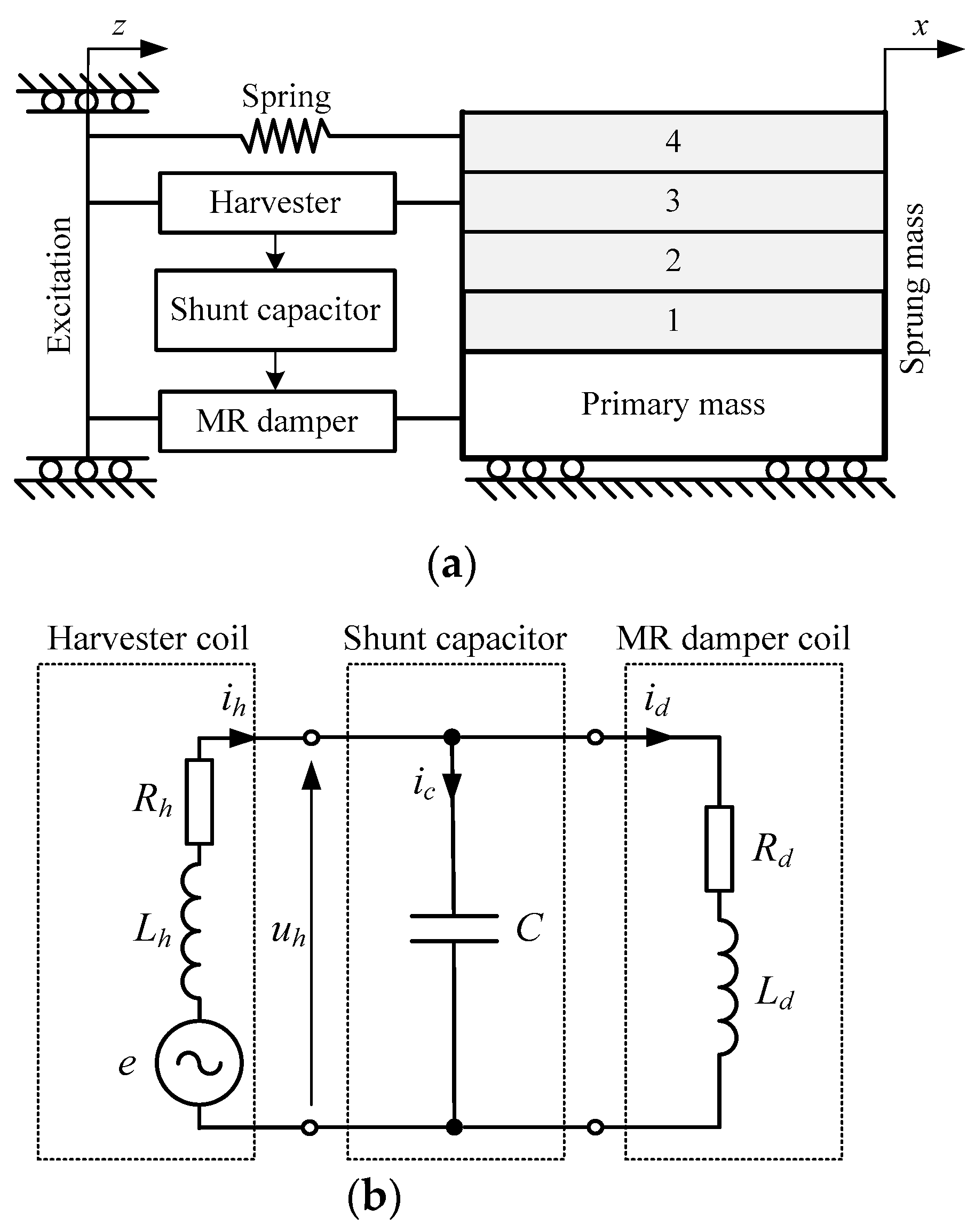
Figure 1. MR-damper-based vibration-reduction system: (a) schematic diagram and (b) equivalent electrical diagram.
Energies 17 03436 g001
Figure 2. Transmissibility Txz vs. frequency f; m = const, various current Id.
Energies 17 03436 g002
Figure 3. Transmissibility Txz vs. frequency f: Id = 0 A, various sprung mass m.
Energies 17 03436 g003
Figure 4. Diagram of experimental set-up.
Energies 17 03436 g004
Figure 5. Transmissibility Txz vs. frequency f at various current in the damper control coil: (a) m = 100 kg; (b) m = 150 kg; and (c) m = 150 kg.
Energies 17 03436 g005
Figure 6. Transmissibility Txz vs. frequency f; various sprung mass m and Id = 0 A.
Energies 17 03436 g006
Figure 7. Electromotive force E vs. frequency f; various sprung mass m and Id = 0 A.
Energies 17 03436 g007
Figure 8. Force Fd vs. frequency f; various sprung mass m and Id = 0 A.
Energies 17 03436 g008
Figure 9. Transmissibility Txz vs. frequency f; various sprung mass m and id = ih.
Energies 17 03436 g009
Figure 10. Voltage Uh vs. frequency f; various sprung mass m and id = ih.
Energies 17 03436 g010
Figure 11. Current Id vs. frequency f; various sprung mass m and id = ih.
Energies 17 03436 g011
Figure 12. Force Fd vs. frequency f; various sprung mass m and id = ih.
Energies 17 03436 g012
Figure 13. Transmissibility Txz vs. frequency f; impact of capacity C: (a) m = 100 kg; (b) m = 150 kg; and (c) m = 150 kg.
Energies 17 03436 g013
Figure 14. Current Ih vs. frequency f; impact of capacity C: (a) m = 100 kg; (b) m = 150 kg; and (c) m = 150 kg.
Energies 17 03436 g014
Figure 15. Current Id vs. frequency f; impact of capacity C: (a) m = 100 kg; (b) m = 150 kg; and (c) m = 150 kg.
Energies 17 03436 g015
Figure 16. Force Fd vs. frequency f; impact of capacity C: (a) m = 100 kg; (b) m = 150 kg; and (c) m = 150 kg.
Energies 17 03436 g016
Table 1. Impact of current in the damper control coil; m = 100 kg.
Id [A]fr [Hz]Q
[-]
J1
[-]
J2
[-]
J3
[-]
ζ
[-]
04.52.9601.2181.7310.4830.169
0.124.71.9170.9701.2910.5010.261
0.165.01.4260.8841.1180.5340.351
0.205.31.1470.8461.0320.5630.436
id = ig5.21.5761.1801.3580.8950.317
Table 2. Impact of current in the damper control coil; m = 150 kg.
Id [A]fr [Hz]Q
[-]
J1
[-]
J2
[-]
J3
[-]
ζ
[-]
03.83.5451.1482.0130.4010.141
0.123.92.2450.8911.4370.4120.223
0.164.11.7080.8121.2310.4400.293
0.204.31.3050.7721.0950.4810.383
id = ig4.21.6271.1081.4430.7940.307
Table 3. Impact of current in the damper control coil; m = 200 kg.
Id [A]fr [Hz]Q
[-]
J1
[-]
J2
[-]
J3
[-]
ζ
[-]
03.34.0361.0252.2100.3450.124
0.123.32.8800.8581.7000.3690.174
0.163.52.1030.7701.4090.3950.238
0.203.71.4300.6981.1430.4310.350
id = ig3.51.7611.0131.5530.6840.284
Table 4. Impact shunt capacitor capacity; m = 100 kg.
C [mF]fr [Hz]Q
[-]
J1
[-]
J2
[-]
J3
[-]
Id = 0 A4.52.9601.21781.73060.4831
9.45.71.7981.18251.47640.7331
18.85.11.8081.04681.41420.5103
28.24.61.6250.93311.25210.4707
37.64.41.7340.91511.23110.4596
Table 5. Impact shunt capacitor capacity; m = 150 kg.
C [mF]fr [Hz]Q
[-]
J1
[-]
J2
[-]
J3
[-]
Id = 0 A3.83.5451.14772.01260.4005
9.45.11.7391.10551.52260.7200
18.84.61.8951.02231.55200.5468
28.24.31.9220.94801.51120.4518
37.64.11.8910.90211.44060.4314
Table 6. Impact shunt capacitor capacity; m = 200 kg.
C [mF]fr [Hz]Q
[-]
J1
[-]
J2
[-]
J3
[-]
Id = 0 A3.34.0361.02502.21040.3454
9.43.61.7730.99331.56750.6434
18.84.21.8760.94231.61590.5369
28.23.91.9620.88911.63010.4497
37.63.81.9810.84061.59230.4002
Disclaimer/Publisher’s Note: The statements, opinions and data contained in all publications are solely those of the individual author(s) and contributor(s) and not of MDPI and/or the editor(s). MDPI and/or the editor(s) disclaim responsibility for any injury to people or property resulting from any ideas, methods, instructions or products referred to in the content.