Article

Stability Control of Grid-Connected Converter Considering Phase-Locked Loop Frequency Coupling Effect

by
Ye Zhang
1,
Haibo Pen
2,* and
Xiaoyu Zhang
3
1
Department of Automation, Taiyuan Institute of Technology, Taiyuan 030000, China
2
School of Electrical and Information Engineering, Tianjin University, Tianjin 300072, China
3
Mining Big Data Institute, China Coal Research Institute, Beijing 100013, China
*
Author to whom correspondence should be addressed.
Energies 2024, 17(14), 3438; https://doi.org/10.3390/en17143438
Submission received: 18 May 2024 / Revised: 2 July 2024 / Accepted: 5 July 2024 / Published: 12 July 2024
(This article belongs to the Section F3: Power Electronics)

Abstract

:
Given the problems that the phase-locked loop frequency coupling effect (PLL-FCE) in a weak grid reduces the quality of the output current waveform and brings challenges to maintaining a steady running of the grid-connected converter (GCC), this paper analyzes the coupling relationship between the FCE of the PLL, grid impedance and the output impedance of GCCs under a weak grid. It elucidates the role of the above coupling relationships in system stability and then proposes a stability optimization control method. Firstly, this paper delves into the frequency coupling phenomenon and its coupling mechanism in GCCs operating within weak grid conditions. Through analysis using small signal disturbance, it elucidates the significance of the PLL-FCE, particularly in medium- and low-frequency ranges, by establishing the coupling admittance model. Secondly, it presents the output impedance model for a three-phase LCL-type GCC, incorporating the characteristics of PLL frequency coupling. This model elucidates the interplay between the GCC’s output impedance, the PLL-FCE and the grid impedance. It also unveils the impact of the PLL-FCE on system stability in weak grid scenarios. Building upon these insights, this paper proposes an enhanced PLL based on the Second-Order Generalized Integrator (SOGI). It provides a detailed parameter design process for implementing these improved PLL structures. Finally, the study conducts simulation and experiment verification under weak grid conditions. The findings indicate that the PLL-FCE indeed undermines the stability of GCCs in the weak grid, with this effect becoming more pronounced as the grid impedance increases. However, the implementation of the SOGI-PLL successfully mitigates the adverse impact of the PLL-FCE on the stability of the converter–weak grid interactive system, thereby enhancing the adaptability of GCCs to weak grid environments.

1. Introduction

As renewable energy sources become more integrated into the power grid, maintaining power quality and system stability becomes increasingly challenging, especially in weak grid conditions. These challenges are expected to escalate further [1,2,3,4]. Phase-locked loops (PLLs) play a vital role in synchronizing renewable energy systems with grid voltage, making them pivotal for ensuring the stability of GCCs [5,6,7,8].
In numerous studies, the stability analysis of GCCs in weak grid conditions is often simplified to the system where a frequency disturbance results in a uniform frequency response [9]. However, this presumption is only valid for high-frequency ranges and does not accurately represent behavior in middle- and low-frequency ranges. Due to the asymmetrical control of the d and q axes within the PLL structure, the input of the PLL is solely the q-axis voltage. This asymmetry introduces frequency coupling into the control system of the GCC, as observed in several studies. Consequently, the GCC exhibits a single-input multiple-output characteristic, causing a frequency disturbance to produce different frequency responses. Neglecting the frequency coupling components of the PLL, even when they are small, can result in inaccurate stability analysis outcomes for GCCs. Research indicates a positive correlation between the coupling component and the bandwidth of the PLL. Consequently, enhancing the bandwidth of the PLL can degrade system stability [10,11].
To solve the above problems, many scholars have proposed various solutions in recent years. In [12], the general form of the inner and outer loop admittance remodeling factors is constructed, and the admittance remodeling factor is properly selected. By reducing the admittance value of the converter, the quality of the grid-connected current is improved, and the purpose of eliminating the frequency coupling characteristics of the converter and suppressing the background harmonics of the power grid is achieved. Reference [13] introduces a single-input single-output (SISO) transfer function-based model to depict the interaction among control loops, facilitating analysis of the correlation between the proportional gain of the current controller and the instability induced by the PLL. Building upon this foundation, a collaborative design method for the PLL and current controller is presented. In [14], the frequency coupling caused by the asymmetry of the control parameters of the PLL control structure and the power outer loop is eliminated by adding a decoupling factor to the current inner loop and the power outer loop of the converter, so that the anti-angle element in the sequence admittance matrix of the converter is 0. Thus, the GCC system is simplified to a SISO system. Reference [15] proposes a method based on q-axis voltage feedforward to weaken the adverse effects of the PLL on system stability. Yet, this approach necessitates supplementary feedforward in the current loop, consequently augmenting the intricacy of the control algorithm. Reference [16] proposed an enhanced control scheme involving series lead phase correction to mitigate the effects of the PLL frequency coupling. In accordance with this method, modifications are required for the frequency coupling impedance form of the wind turbine. Reference [17] compensates the phase of the output impedance of the GCC by adding a phase correction link. However, this method requires an accurate oscillation frequency and exhibits poor robustness. In [18], a differential feedforward mechanism is introduced, incorporating the output current differential into the input voltage of the PLL. This approach effectively severs the coupling between the grid impedance and the PLL, especially in scenarios of weak grid conditions. Moreover, it maintains system stability even amidst fluctuating system parameters. However, it is worth noting that the differential component within the feedforward path may amplify high-frequency noise present in the current. This, in turn, can adversely impact the phase tracking accuracy of the PLL concerning the grid, particularly in severe instances. Reference [19] adds voltage feedforward to the d-axis control loop to offset the d-axis of the current controller. The research results show that the introduced d-axis voltage can suppress the asymmetry of the system. In [20], a constant low-coupling PLL structure is designed. The designed PLL does not affect the impedance of the GCC and can realize the decoupling between the PLL and the GCC control. In [21], a symmetric PLL control method is proposed to eliminate the FCE caused by the PLL by introducing the real phase angle and the imaginary phase angle. In addition, for the stability analysis and guarantee research of linear and nonlinear systems, some scholars have proposed some linear control methods. In [22], a novel adaptive interleaved reinforcement learning algorithm is developed so that the uniformly ultimately bounded stability of discrete-time affine nonlinear systems can be guaranteed. In [23], a robust asynchronous fuzzy predictive fault-tolerant tracking control method is proposed to ensure stable system operation. A fault-tolerant tracking control method with robustness is proposed for industrial production systems with uncertainty, set-point changes, external bounded disturbances and partial actuator failures. Reference [24] put forward a robust predictive fault-tolerant switching control method to predict robustness of a discrete linear system. And the above methods can provide some new ideas for enhancing stability of GCCs.
The aforementioned literature investigates the impact of PLL frequency coupling on the output characteristics of GCCs in weak grid scenarios, along with proposing optimal control schemes. However, there remains a lack of clarity regarding the influence of the grid impedance on the output admittance/impedance of GCCs under PLL frequency coupling in weak grids. Furthermore, existing methods for enhancing the stable operating ability of the system primarily revolve around implementing phase/voltage compensation in control loops and parameter design based on stability region. It is therefore imperative to delve deeper into the relationship between the grid impedance and the output impedance of GCCs under PLL-FCEs, aiming to mitigate these effects and enhance system stability. This paper studies the influence of the PLL-FCE on the stability of GCCs and robust control methods in weak grids. The main contributions are as follows: (1) The coupling admittance model is developed to reveal how the PLL-FCE influences the output impedance and system stability across different frequency ranges; (2) The output impedance model for GCCs with PLL frequency coupling characteristics is established, providing a theoretical foundation for understanding low-frequency oscillation phenomena of GCCs in weak grids; (3) An analysis of the relationship between the PLL-FCE, grid impedance and output impedance of grid-connected inverters is conducted to offer design insights and a theoretical basis for enhancing inverter stability.The rest of the paper is organized as follows: In Section 2, the frequency coupling traits of the PLL are delved into via small signal voltage disturbance. In Section 3, the output impedance of the GCC under the frequency coupling characteristics is constructed. Additionally, how the FCE of the PLL impacts the stability of the GCC is scrutinized, particularly under weak grid conditions. In Section 4, a scheme for suppressing the FCE of the PLL and optimizing system stability is presented. In Section 5, a theoretical analysis and the efficacy of the optimization scheme are validated through simulation and experimentation. In Section 6, some conclusions are drawn.

2. Frequency Coupling Mechanism of PLL

The voltage disturbance signal Δup of ωp is injected at PCC, and it is expressed as after the Clark and Park transformation:
Δ u p α Δ u p β = Δ u p cos ( ω p t + φ p ) sin ( ω p t + φ p ) Δ u p d q = Δ u p e j ω p ω 0 t j U 1 Δ θ
where ωp, φp, Δup represent the frequency, initial phase and amplitude of the disturbance voltage Δup; Δupα,β, Δupd,q are the expressions of Δup in the static and rotating coordinate systems; Δθ is the disturbance phase; and U1 denotes the amplitude of the fundamental voltage at PCC.
The Synchronous Reference Frame PLL(SRF-PLL) realizes phase tracking by regulating the q-axis voltage at PCC, and it can be expressed as
Δ u p q = 0.5 j Δ u p d + j Δ u p q ω p ω 0 + 0.5 j Δ u p d j Δ u p q ω p ω 0
Thus, Δθ can be equivalent to the complex phase angles of positive and negative sequences [25]:
Δ θ = 0.5 j T PLL ω p ω 0 Δ u p e j ω p ω 0 t Δ θ + + 0.5 j T PLL ω 0 ω p Δ u p e j ω p ω 0 t Δ θ
For the expression of TPLL, we can refer to [21].
Therefore, Δupd,q in (1) is given as
Δ u p d q = Δ u p d q , ω p ω 0 t + Δ u p d q , ω 0 ω p t
Then, (1), (3) and (4) can be obtained simultaneously:
Δ u p d q , ω p ω 0 t = 1 0.5 U 1 T PLL ω p ω 0 Δ u p , ω p e j ω p ω 0 t Δ u p d q , ω 0 ω p t = 0.5 U 1 T PLL ω p ω 0 Δ u p , ω p e j ω 0 ω p t
According to (4) and (5), a small signal disturbance of frequency ωp at PCC results in two frequency responses in the dq coordinate due to the asymmetry control of the PLL. These responses are namely ωp-ω0 and ω0-ωp, leading to a coupling current of the ωp-ω0 frequency disturbance current and ω0-ωp frequency current in the grid-connected current. Upon applying the inverse Park transformation, these frequencies become ωp and 2ω0-ωp. The above phenomenon is called the PLL-FCE, that is, owing to the asymmetry control of the PLL in weak grids, a single-frequency disturbance voltage will stimulate a multi-frequency current response. The frequency relationship of the voltage disturbance and the current response is shown in Figure 1.

3. Impact of PLL-FCE on the Output Impedance and Operating Characteristics of GCCs

3.1. Coupling Admittance Modeling

This paper introduces coupling admittance as a quantitative measure to assess the impact of PLL frequency coupling on the output impedance and operating characteristics of GCCs. Through the construction of a coupling admittance model, the paper analyzes how the PLL-FCE influences the output impedance and system stability.
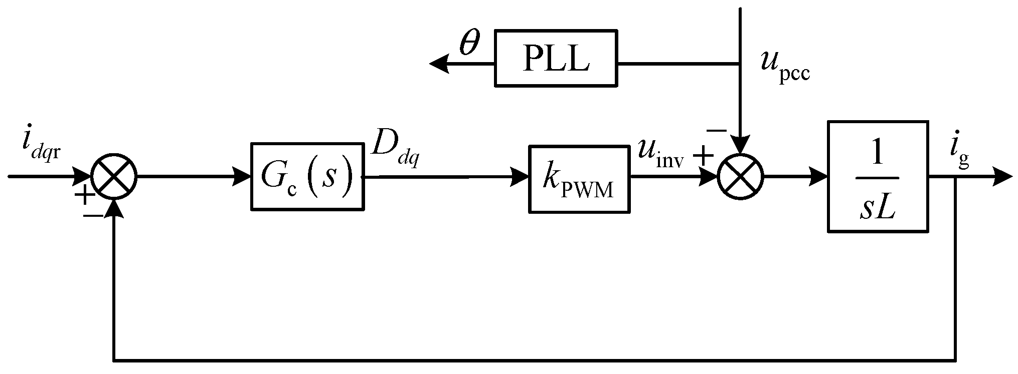
In the context of an LCL filter, the primary function of a filter capacitor is to absorb the high-frequency component of the grid-connected current. However, it is noteworthy that the PLL-FCE predominantly influences the operating characteristics within the bandwidth of the PLL. Therefore, the LCL filter could be considered as an L-type filter during the coupling admittance modeling, and Figure 2 depicts the control system.
In the above figure, idqr, ig, Ddq, kPWM, uinv and Gc(s) represent the current reference value, grid-connected current sampling value, duty cycle, PWM modulation coefficient, converter output voltage and current controller, respectively; L represents the sum of filter inductors L1 and L2.
The small signal expression of the disturbance loop under the coupling current in stationary coordinates is
d p , 2 ω 0 ω p k PWM = j 2 ω 0 s L i p , 2 ω 0 ω p
where i p , 2 ω 0 ω p , d p , 2 ω 0 ω p denote the coupling current phasor and duty cycle phasor with 2ω0−ωp, respectively.
The small signal representation of the coupling loop under the coupling current in the rotating coordinate is as follows:
d p , ω 0 ω p = i p d q , ω 0 ω p G c j ω 0 s
The expressions of i p d q , ω 0 ω p , d p , 2 ω 0 ω p are [26]
i p d q , ω 0 ω p = i p , 2 ω 0 ω p + 0.5 i d q T PLL j ω 0 s u p , ω p d p d q , ω 0 ω p = d p , 2 ω 0 ω p + 0.5 d d q T PLL j ω 0 s u p , ω p
where “*” denotes the conjugate component.
Combining the above, (6)–(8), we can obtain
d p , 2 ω 0 ω p s = G c j ω 0 s i p , ω p 0.5 T PLL j ω 0 s i d q r G c j ω 0 s + d d q u p , ω p
Substituting (9) into (6) yields
Y c ( s ) = i p , 2 ω 0 ω p u p , ω p = 0.5 k PWM T PLL ( j ω 0 s ) i d q r G c j ω 0 s + d d q ( j 2 ω 0 s ) L + k PWM G c j ω 0 s
The coupling admittance amplitude ∣Yc(s)∣ reflects the coupling strength under PLL frequency coupling characteristics. It can also be seen from the numerator term of (10) that Yc(s) is positively correlated with TPLL(0-s), and it exerts a key influence on Yc(s). Since the PLL only impacts the operational characteristics of the converter during its bandwidth [17], we can deduce that the coupling admittance predominantly shapes the output impedance characteristics of the GCC within the medium- and low-frequency spectrum.
Similarly, we can derive the output admittance model of the GCC without accounting for the PLL-FCE:
Y s ( s ) = i p , ω p u p , ω p = 1 0.5 k PWM T PLL ( s j ω 0 ) i d q r G c s j ω 0 + d d q s L + k PWM G c s j ω 0
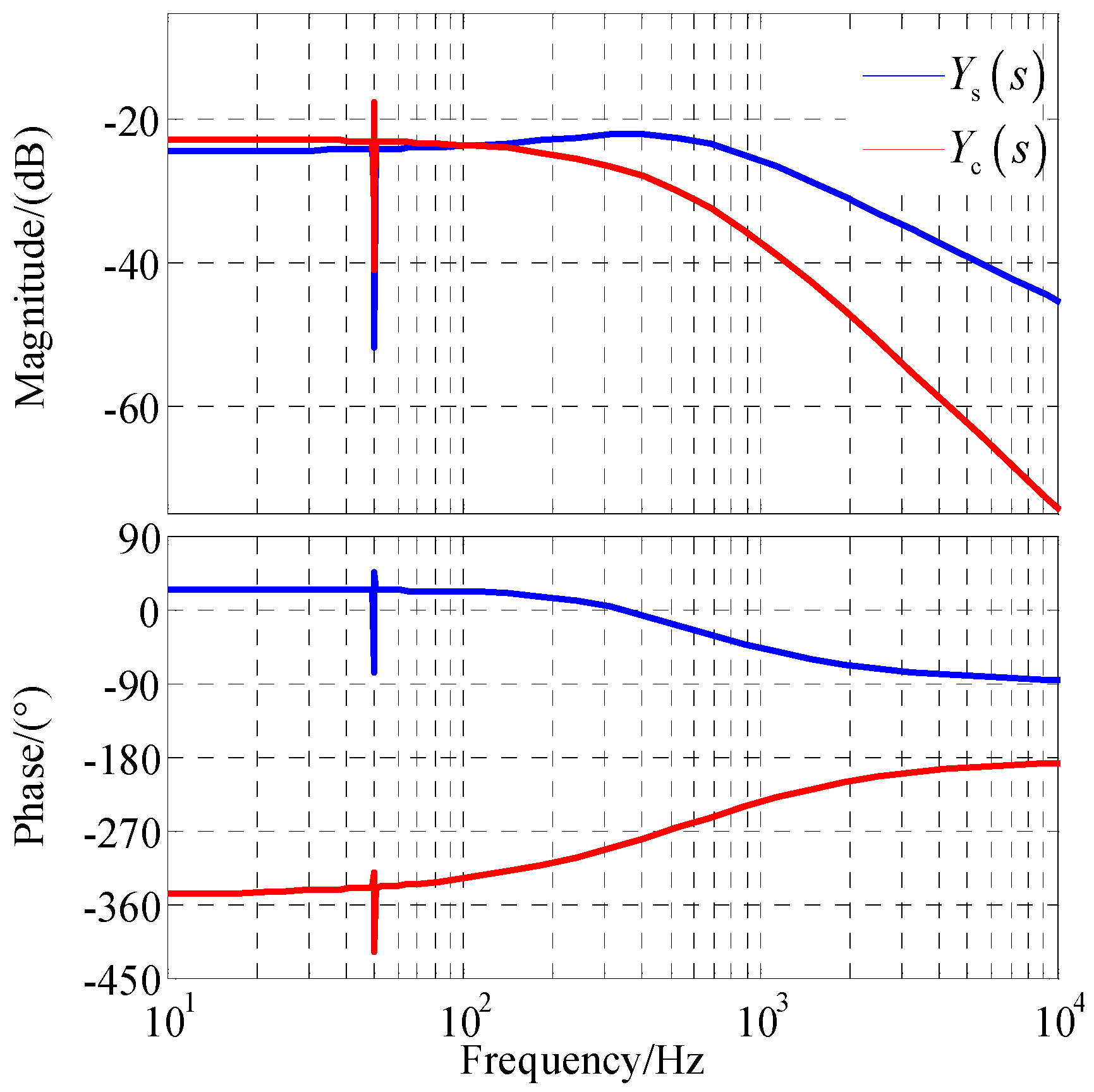
The Bode diagram of Yc(s) and Ys(s) can be obtained from (10) and (11), and it is depicted in Figure 3. It is found that when the disturbance voltage frequency is 0 < fp < 100 Hz, the amplitude of Yc(s) is greater than that of Ys(s), indicating that the PLL-FCE plays a leading role. While fp > 100 Hz, although the amplitude of Ys(s) is higher than that of Yc(s), the impact of Yc(s) is still not negligible in the range of 1000 Hz.

3.2. Output Impedance Modeling for GCCs under the PLL Frequency Coupling Characteristics

It has been deduced that the PLL-FCE introduces both disturbance and coupling loops in the converter–grid system. This coupling loop notably impacts the output characteristics, particularly in the low-frequency range. Consequently, an output impedance model that incorporates the coupling loop is formulated to elucidate how the PLL-FCE influences the stability of the GCC grid system.
The grid-side current is considering the PLL frequency coupling characteristics under small signal disturbance can be expressed as
i s = i s , ω p + i s , 2 ω 0 ω p
Considering the non-negligibility of grid impedance in weak grids, it is crucial to acknowledge that the PCC voltage comprises both the disturbance voltage component and the coupling voltage component:
u pcc = u pcc , ω p + u pcc , 2 ω 0 ω p
The relations among the disturbance voltage, current and the coupling voltage are derived in (14):
u pcc , ω p = u s , ω p i s , ω p Z wg ω p u pcc , 2 ω 0 ω p = i s , 2 ω 0 ω p Z wg 2 ω 0 ω p
where Zwg denotes the grid impedance in the weak grid.
By combining (12)−(14), the relationship among the disturbance voltage, the disturbance current and the coupling current is deduced in (15):
i s , ω p = Y s s u pcc , ω p + Y c j 2 ω 0 s u pcc , 2 ω 0 ω p i s , 2 ω 0 ω p = Y s j 2 ω 0 s u pcc , 2 ω 0 ω p + Y c s u pcc , ω p
where u pcc , ω p , u pcc , 2 ω 0 ω p represent the conjugate of the disturbance voltage and the coupling voltage, respectively.
The equivalent impedance model of the three-phase GCC considering the PLL-FCE can be obtained from (12)–(15):
Z FCE ( s ) = 1 + Z wg j 2 ω 0 s Y s j 2 ω 0 s Y s ( s ) + Y s ( s ) Z wg j 2 ω 0 s Y s j 2 ω 0 s Y c j 2 ω 0 s Y c s Z wg j 2 ω 0 s
Comparing (11) and (16), it can be seen that ZFCE(s) and Zs(s) (corresponding to 1/Ys(s)) are equal and only related to the transfer function of the PLL, while the PLL-FCE is disregarded. The equivalent output impedance ZFCE(s) in the absence of taking into account the PLL-FCE is not only related to Ys(s) and Yc(s) but is also affected by grid impedance. The above phenomenon can be explained as follows.
The PLL-FCE results in the GCC having both a disturbance loop and a coupling loop when subjected to disturbance voltage. This, in turn, causes the grid-side current to be generated by two components: the effect of the disturbance voltage and the effect of the coupling voltage formed by the coupling current and the grid impedance Zwg. Therefore, when modeling the impedance of the GCC, the grid impedance will be introduced.

3.3. Stability Analysis of GCCs under PLL Frequency Coupling Characteristics

According to (16), the Bode diagram of ZFCE(s) under various grid impedances is generated, depicted in Figure 4. It is found in Figure 4 that the presence of the PLL-FCE alters the amplitude of the GCC’s output impedance, diminishes its phase in the medium- and low-frequency range and heightens the likelihood of instability. Furthermore, as the grid impedance Zwg escalates, this effect exacerbates, intensifying the aforementioned phenomenon.
To explore how the PLL-FCE influences the stability assessment, an analysis is conducted to compare the system’s stability before and after accounting for this effect. The open-loop transfer functions of the system in both cases are Top0(s) and Top(s):
T o p 0 s = Y s s Z wg s T o p s = Y FCE s Z wg s
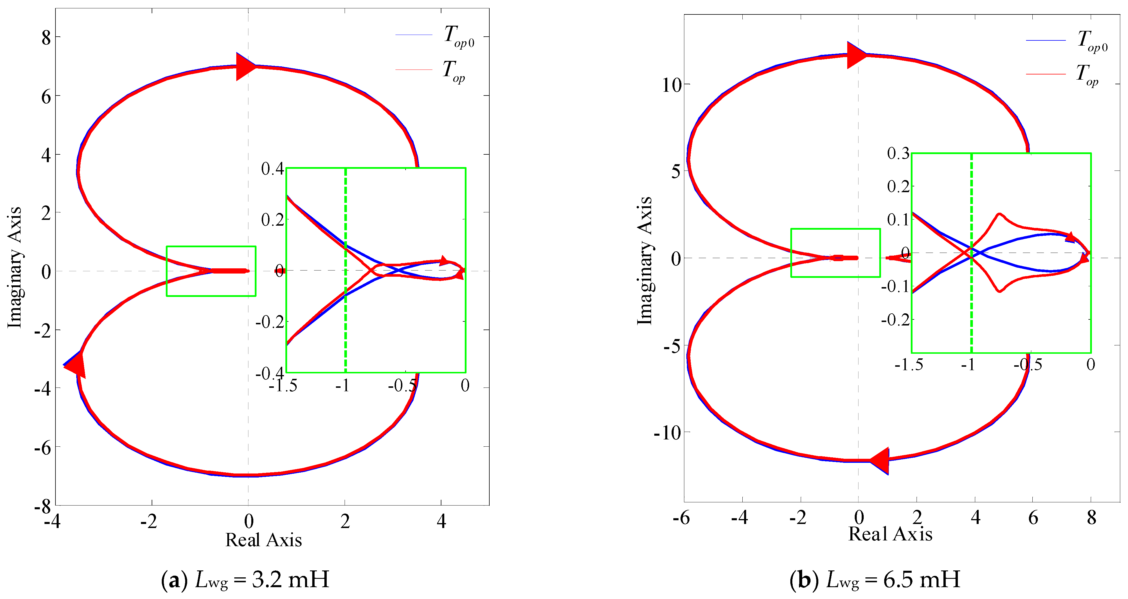
Lwg is taken as 3.2 mH and 6.5 mH, with corresponding SCR values of 9.5 and 4.5, respectively.
Figure 5 presents the Nyquist curves of Top0(s) and Top(s) when Lwg = 3.2 mH and 6.5 mH, respectively. It is evident that when not considering the PLL-FCE, the Nyquist curves of Top0(s) do not encircle (−1, j0) for both Lwg = 3.2 mH and 6.5 mH, indicating stable operation of the GCC. However, upon considering the PLL-FCE, the Nyquist curve of Top(s) is not surrounded (−1, j0) when Lwg = 3.2 mH. Yet, as Lwg progressively increases, in Figure 5b, it is observable that with Lwg = 6.5 mH, the Nyquist curve of Top(s) does enclose (−1, j0), signaling instability in the GCC system.
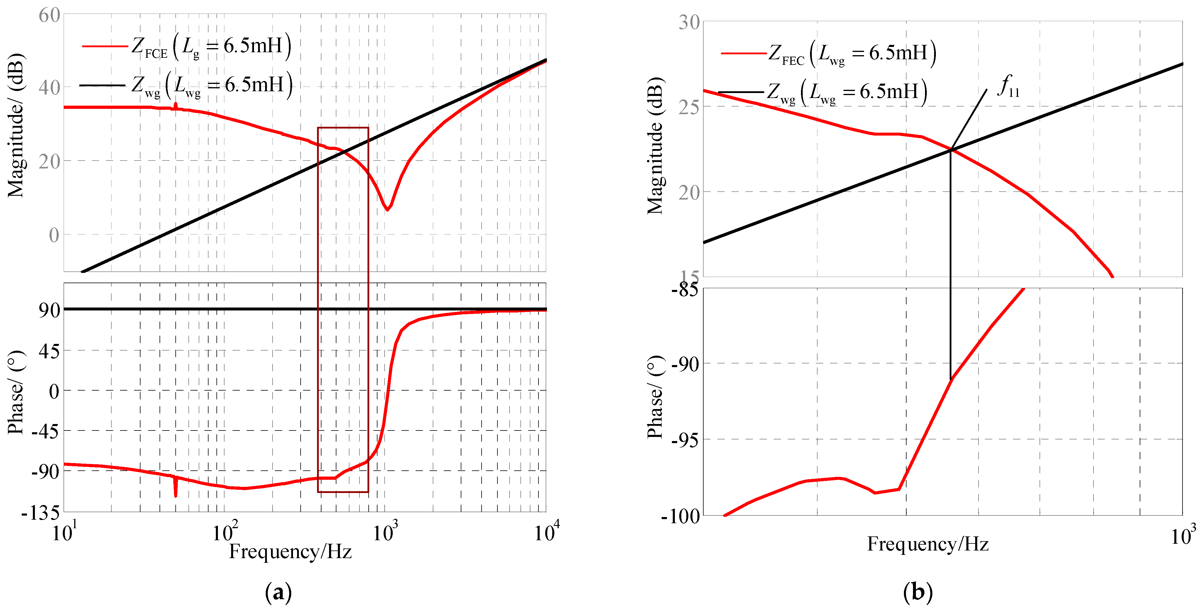
To address the limitation of the Nyquist curves in directly conveying frequency and phase information regarding the unstable point of the GCC, Figure 6 illustrates the Bode diagrams of Zwg(s) and ZFCE(s) when Lwg = 6.5 mH. As depicted in Figure 6, taking into account the PLL-FCE, when Lwg = 6.5 mH, the phase angle margin δPM of the GCC at the intersection frequency f11 (552 Hz) is −1.2°. This indicates that harmonic oscillation will occur at f11 and its coupling frequency (452 Hz) in this case.
The analysis highlights the substantial impact of the PLL-FCE on the medium- and low-frequency characteristics of the GCC’s equivalent output impedance. This effect results in the equivalent output impedance being affected by both Yc(s) and the grid impedance Lwg. Notably, an increase in Lwg intensifies its effect on the low-frequency characteristics of ZFCE(s). Neglecting to account for the PLL-FCE during stability analysis can lead to discrepancies in results for GCCs, thereby affecting parameter selection and operational stability. Consequently, mitigating the PLL-FCE becomes imperative to minimize its detrimental impact on the stability of the converter–grid system.

4. Strategy to Suppress the PLL-FCE

4.1. Second-Order Generalized Integral-Based PLL

Reference [27] has pointed out that embedding the second-order low-pass filter in the PLL can restrain the adverse impact of the PLL on the stable operation of the system. However, this method requires adding phase compensation.
The Orthogonal Signal Generator (OSG) in the Second-Order Generalized Integrator Phase-Locked Loop (SOGI-PLL) also has the harmonic attenuation function. Therefore, this section proposes to use the SOGI-PLL to inhabit the PLL coupling strength, thus improving the stability of the GCC grid system. Figure 7 depicts the structure of the SOGI-PLL.
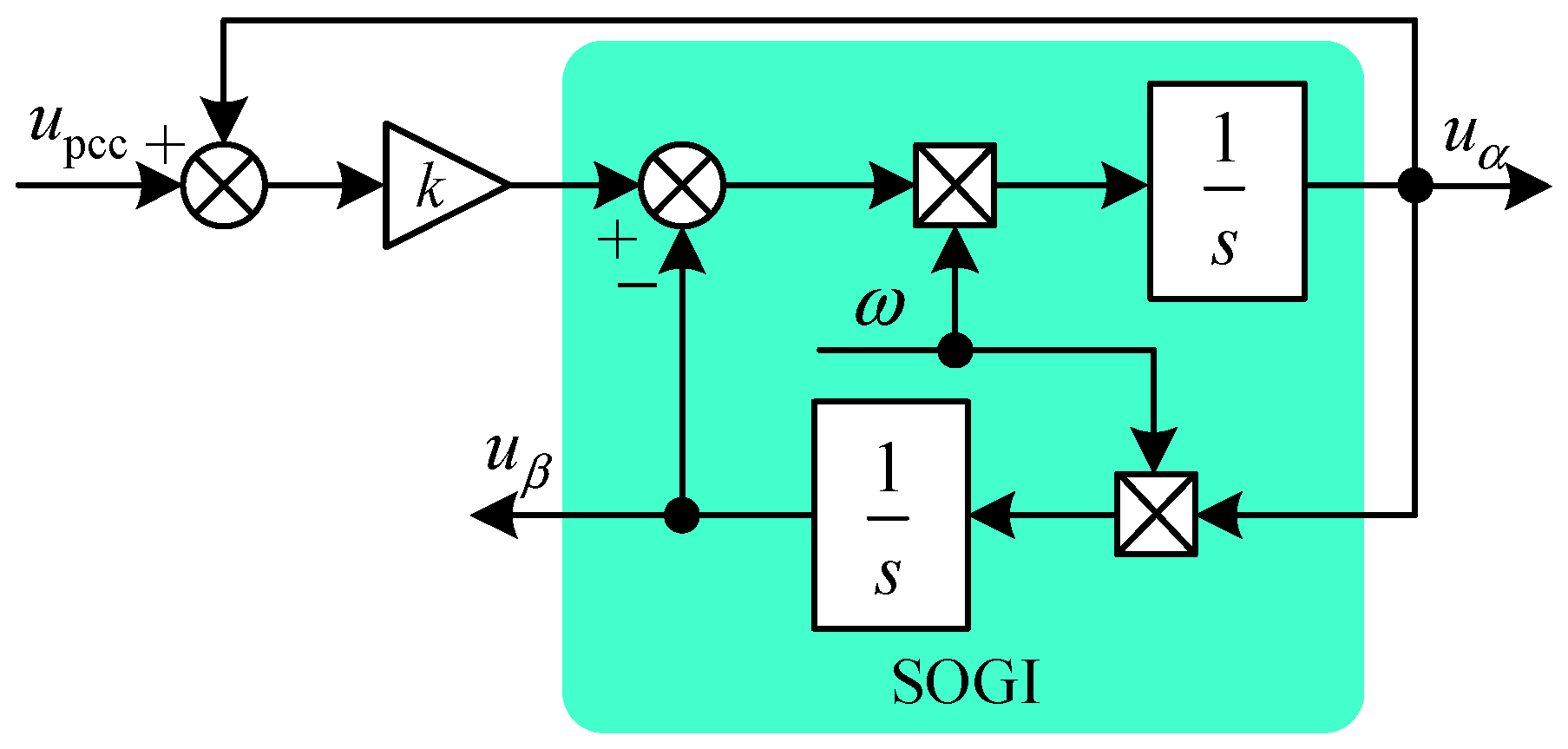
In this above figure, the Orthogonal Signal Generator uses a Second-Order Generalized Integrator.
The structure of the OSG is illustrated in Figure 8. Here, k represents the bandwidth coefficient, and ω1 denotes the resonant frequency of SOGI.
From Figure 8, we can derive the relationship between uα and upcc:
u α = k ω 1 s s 2 + k ω 1 s + ω 1 2 u pcc = D s u pcc
Therefore, the transfer function of SOGI-PLL is
T PLL _ SOGI s = H PLL ( s ) 1 + U 1 H PLL ( s ) k ω 1 s s 2 + k ω 1 s + ω 1 2
The parameters of the SOGI-PLL are designed as follows:
(1) Choose ω1.
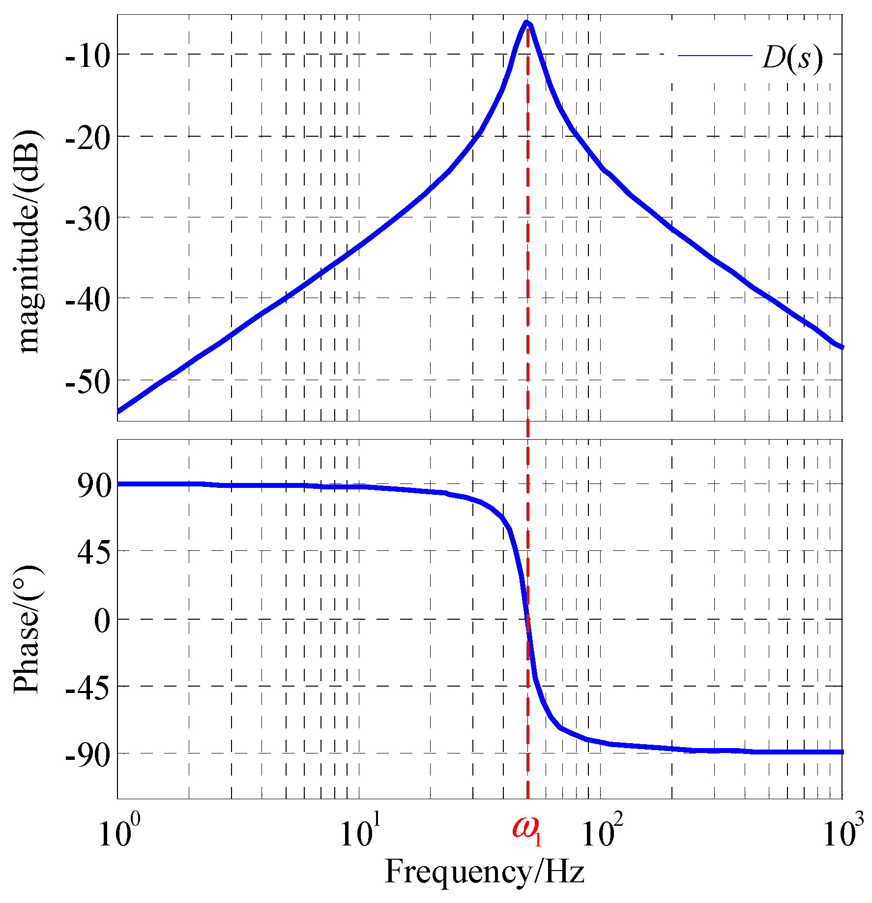
The Bode diagram of D(s) can be derived from Equation (18), and it is depicted in Figure 9. It is observed that D(s) does not possess attenuation capability at ω1, but it exhibits good attenuation at frequencies other than ω1 and does not exhibit phase deviation at ω1.
Therefore, ω1 = 100π is selected in this section. At this time, it can ensure that the signal at the fundamental frequency is not attenuated while avoiding the problem of phase lag/lead at the fundamental frequency caused by adding the OSG.
(2) Choose k.
The expression of ZSOGI(s) with SOGI-PLL in the mid- and low-frequency range can be approximately denoted as
Z SOGI s 1 I ref T PLL _ SOGI s j ω 0
Then, the phase of ZSOGI(s) at 200 Hz is
arg Z SOGI j 2 π 200 = 90 + arg T PLL ( j 2 π 200 ) arctan 400 π k ω 1 ω 1 2 + j 2 π 200 2
The phase margin δPM of ZSOGI(s) at 200 Hz can be expressed as
δ PM = 90 ° + arg Z SOGI j 2 π 200
Consider a certain margin: take δPM = 20°. By solving (22), it is obtained that k > 0. As the parameter k decreases, the gain attenuation effect becomes more pronounced. However, excessively small values of k can lead to a reduction in the system’s response speed. Taking these factors into account, k is chosen as 1.414.

4.2. Performance of SOGI-PLL

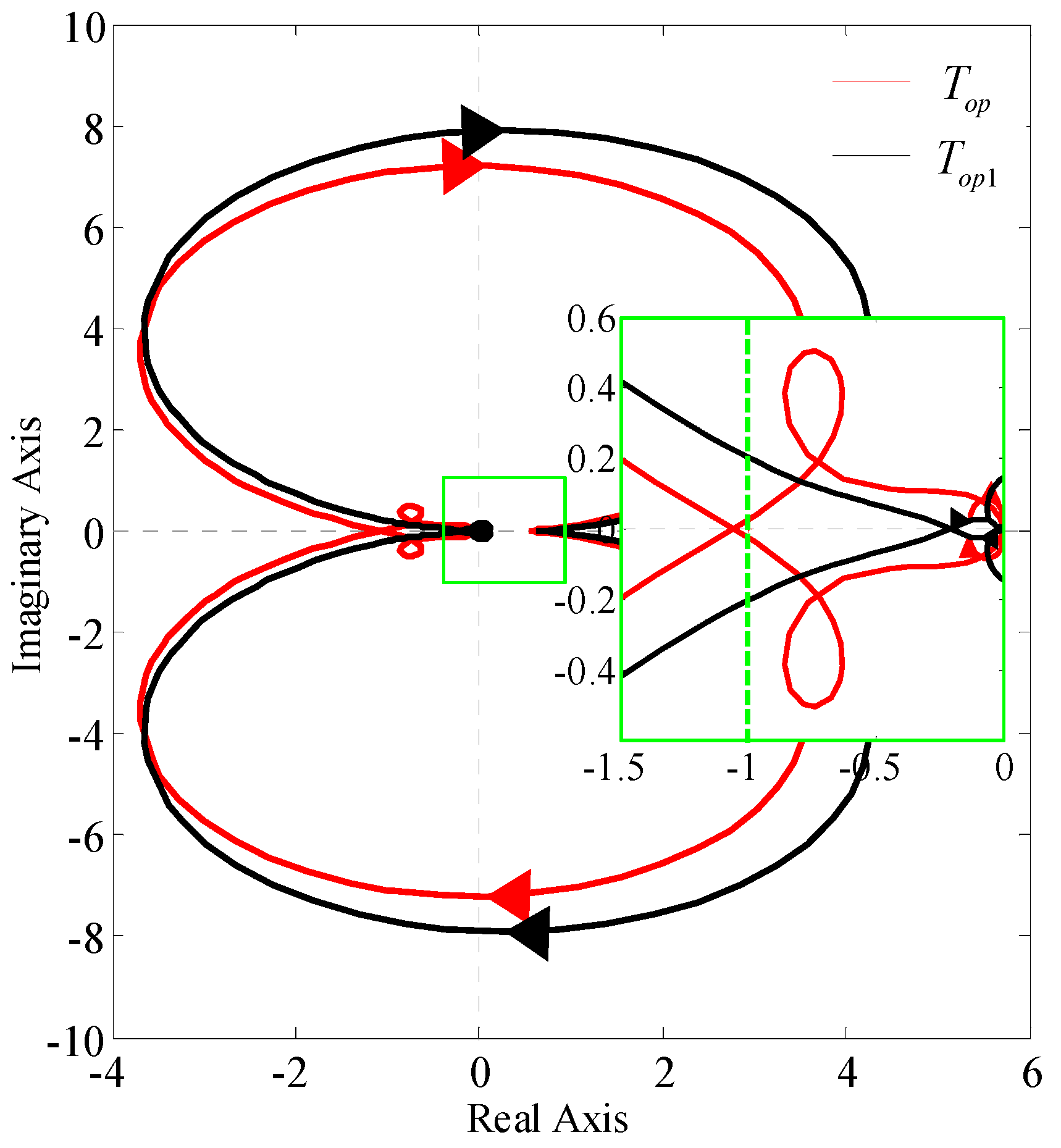
To assess the efficiency of the SOGI-PLL, the Nyquist curves of the open-loop transfer function of the system under various impedances are analyzed, and Figure 10 shows the Nyquist curves of Top(s) and Top1(s) when Lwg = 6.5 mH. Here, the expression of Top1(s) is
T o p 1 s = Y SOGI s Z g s
where YSOGI represents the output admittance while employing the SOGI-PLL.
Figure 10 indicates that when Lwg = 6.5 mH, the Nyquist curves of Top1(s) with SOGI-PLL do not encircle the point (−1, j0). This observation suggests that the utilization of the SOGI-PLL can ameliorate the instability problem of GCCs arising from FCEs in conditions of weak grids. This is due to the fact that the OSG in the SOGI-PLL constructs the voltage uα and uβ in the αβ coordinate system based on the PCC voltage input upcc. This has an impact on the PLL transfer function TPLL(s), leading to changes in the magnitude of the FCE, which subsequently alters the output impedance characteristics and stability of grid-connected inverters operating in weak grids.

5. Simulation and Experimentation Verification

To verify the accuracy of the theoretical analysis and the efficacy of the SOGI-PLL, simulation and experiment setups of the GCC were established, with detailed parameters outlined in Table 1.

5.1. Simulation Results

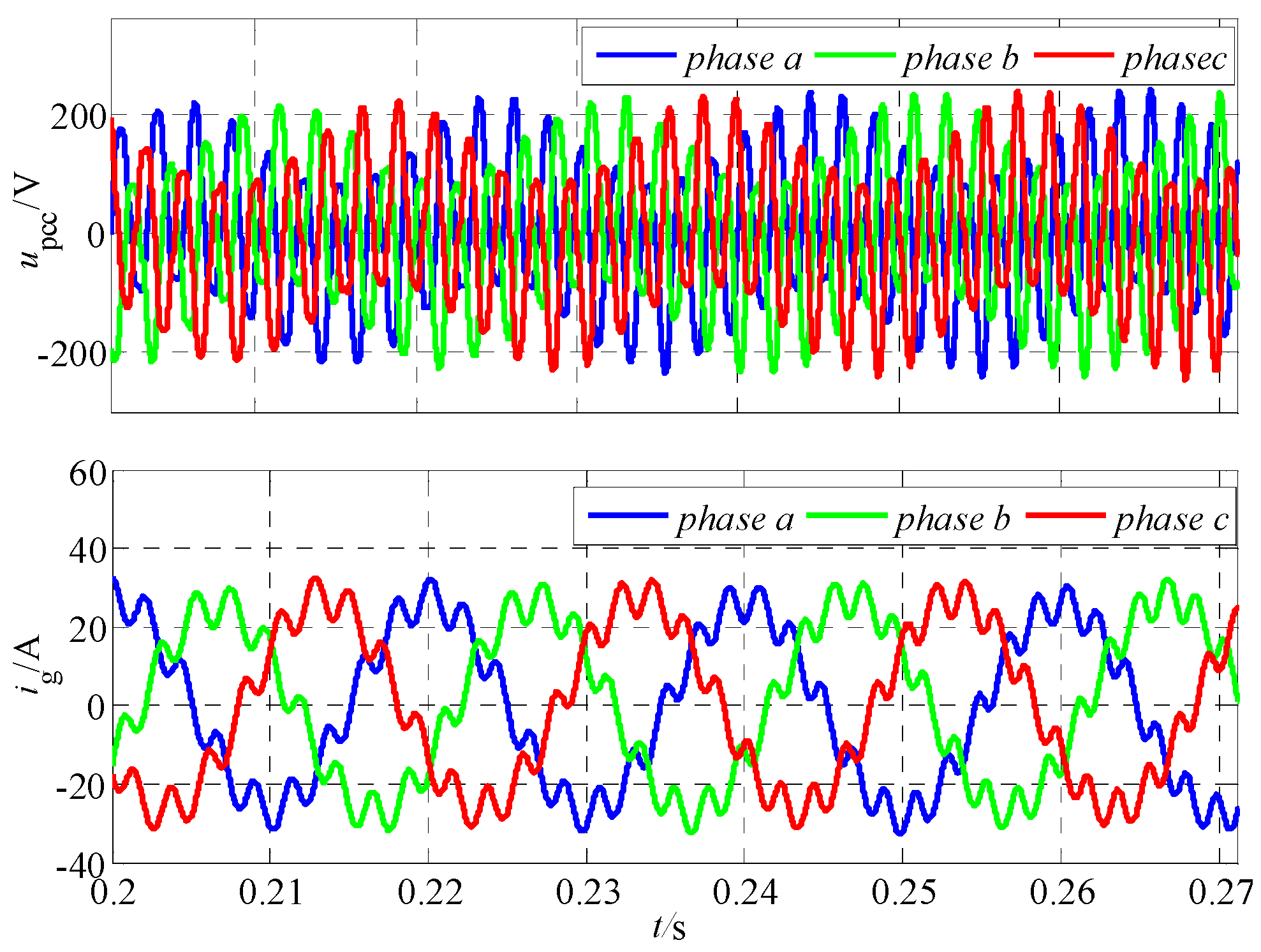
Figure 11 depicts the simulation results for the voltage upcc and the output current ig under a 20 Hz voltage disturbance at the PCC, with Lwg = 3.2 mH (where the GCC can maintain stable operation). It is notable to find that the grid current ig demonstrates low-frequency oscillations.
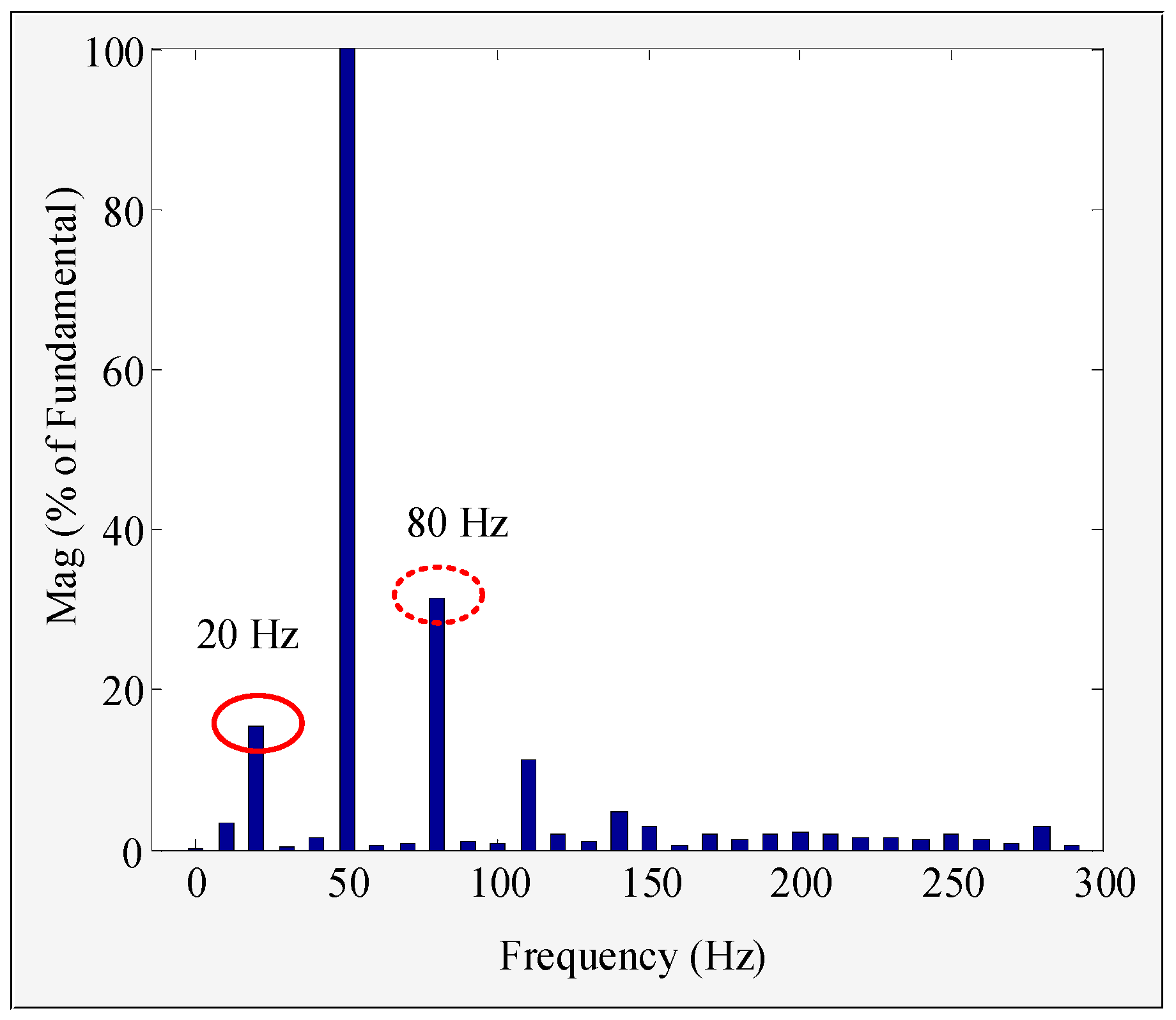
A Fourier spectrum analysis of the output current was conducted, and the outcomes of the harmonic spectrum analysis are presented in Figure 12. It is evident that the grid-side current spectrum content at 20 Hz and 80 Hz is high, indicating that a 20 Hz disturbance at PCC voltage results in a disturbance current at 20 Hz and a coupling current at 80 Hz. This finding underscores the significance of the PLL-FCE, which cannot be overlooked.
To elucidate the impact of PLL-FCEs on the stable operation of GCCs in weak grids, simulations were performed with two different grid impedances: Lwg = 3.2 mH and Lwg = 6.5 mH. Figure 13 illustrates the simulation results for upcc and ig when Lwg = 3.2 mH and there is no voltage disturbance. It is found that the GCC demonstrates stable operation at Lwg = 3.2 mH, in line with the analytical conclusion depicted in Figure 5a. This coherence validates the accuracy of the theoretical analysis.
By increasing the grid impedance to Lwg = 6.5 mH, the simulation results for upcc and ig when Lwg = 6.5 mH using the traditional PLL are illustrated in Figure 14. It is evident from the results that at Lwg = 6.5 mH, the grid current displays significant low-frequency oscillations, indicating an unstable operating state of the GCC under this circumstance.
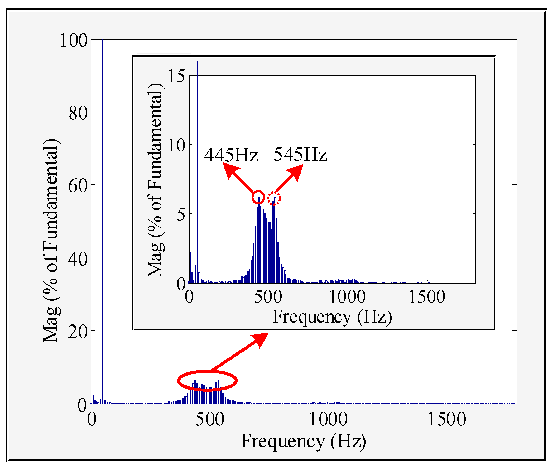
Figure 15 shows the FFT diagram of ig when Lwg = 6.5 mH. It is notable from Figure 15 that the resonant points for the grid current primarily concentrate at 445 Hz and 545 Hz. Furthermore, 545 Hz closely aligns with the intersection frequency f11 in the Bode diagram depicted in Figure 9, while 445 Hz represents the coupled unstable frequency point of f11. This indicates that under higher grid impedance, the PLL-FCE will diminish the stable operation ability of GCCs in weak grid circumstances, leading to simultaneous oscillations at both the resonant frequency and its coupled frequency. As a result, severe low-frequency oscillations are exhibited in the output current, and this phenomenon aligns with the theoretical investigation.
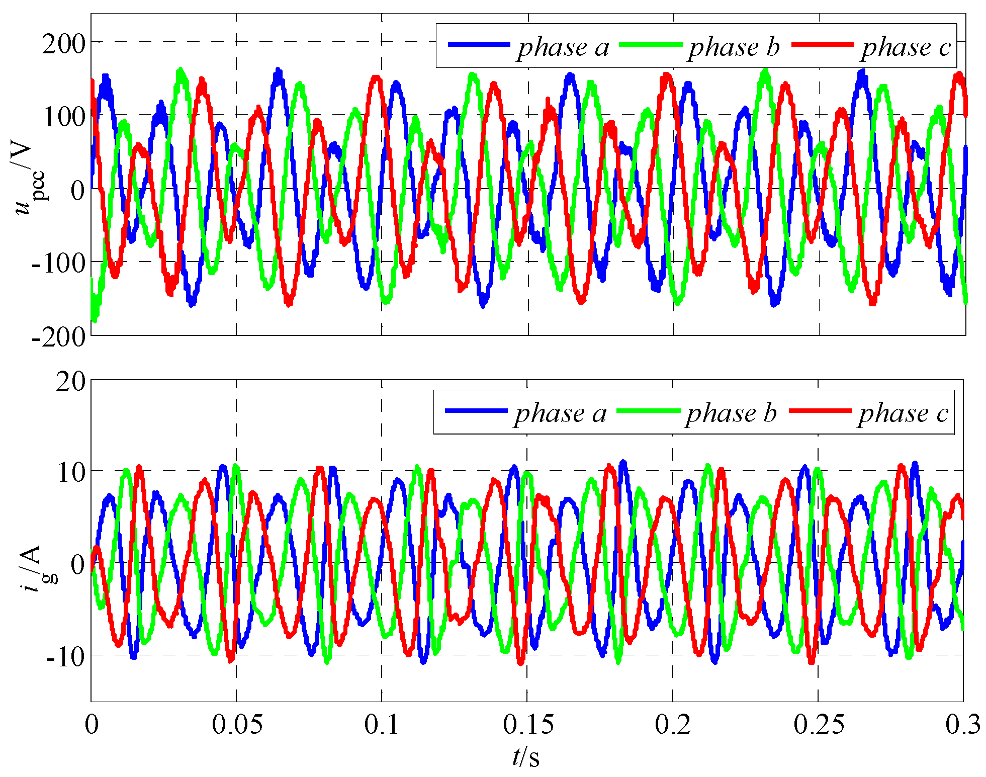
To tackle this issue, a SOGI-PLL is designed in this paper. Figure 16 illustrates the transient simulation results for upcc and ig employing the SOGI-PLL at t = 0.3 s with a grid impedance of Lwg = 6.5 mH. The stable operation of the GCC is evident, indicating that the SOGI-PLL can effectively mitigate the PLL-FCE, thereby enhancing the stability of three-phase GCCs under weak grid circumstance. This is because with the action of the OSG in the SOGI-PLL, the transfer function TPLL, which characterizes the frequency coupling effect of the PLL, has a certain attenuation ability on harmonic voltage. The phase angle margin corresponding to the transition frequency of the impedance amplitude frequency curve gradually increases, and the stability of the grid-connected system gradually improves.

5.2. Experiment Results

To further confirm the negative impact of the PLL-FCE on the stability of the GCC–grid interactive system and the effectiveness of the designed PLL, a GCC hardware platform was constructed, as shown in Figure 17.
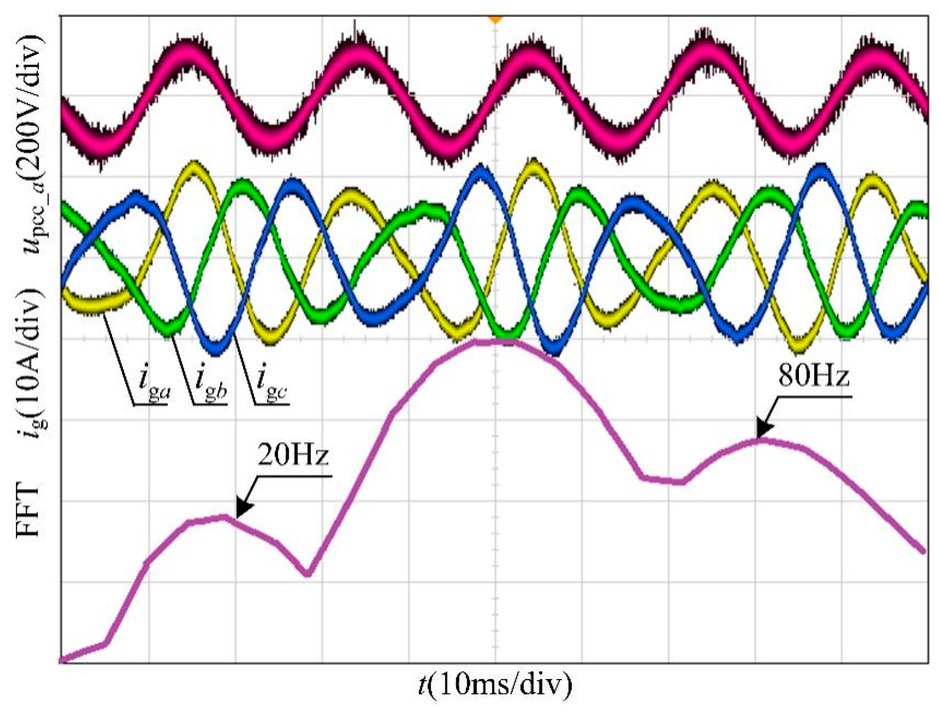
Figure 18 displays the experiment results for a-phase voltage at PCC upcc_a and the output current ig when Lwg = 3.2 mH with a 20 Hz harmonic disturbance voltage, along with the Fourier spectrum of ig. It can be observed that when a 20 Hz harmonic disturbance voltage is present in the grid voltage, the asymmetrical control of the PLL induces the FCE, resulting in low-frequency oscillations and distortion in ig. During this scenario, the output current ig encompasses both the 20 Hz disturbance current and the 80 Hz coupled current, with the latter being more pronounced than the former. This implies that under the conditions of a weak grid, the PLL-FCE introduces response currents at frequencies of ωp and 2ω0-ωp in the output current when a disturbance voltage with a frequency of ωp is present. This experiment finding corroborates the simulation outcomes depicted in Figure 11 and Figure 12, thereby reinforcing the accuracy of the theoretical investigation.
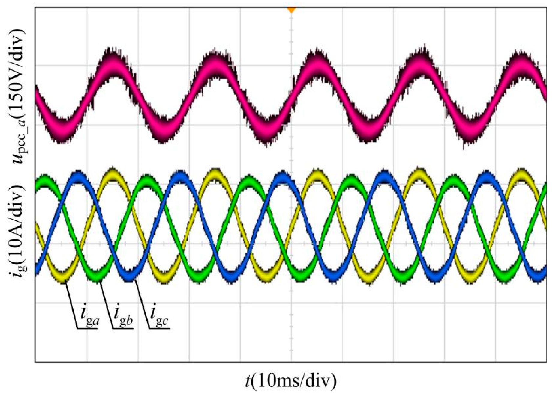
Figure 19 depicts the experiment results for the a-phase voltage at PCC upcc_a and ig without voltage harmonic disturbances when utilizing the traditional PLL with a grid impedance of Lwg = 3.2 mH. It is evident from the observation that the GCC operates steadily in this condition, affirming that the traditional PLL could uphold the stability of GCCs when the grid impedance is relatively low.
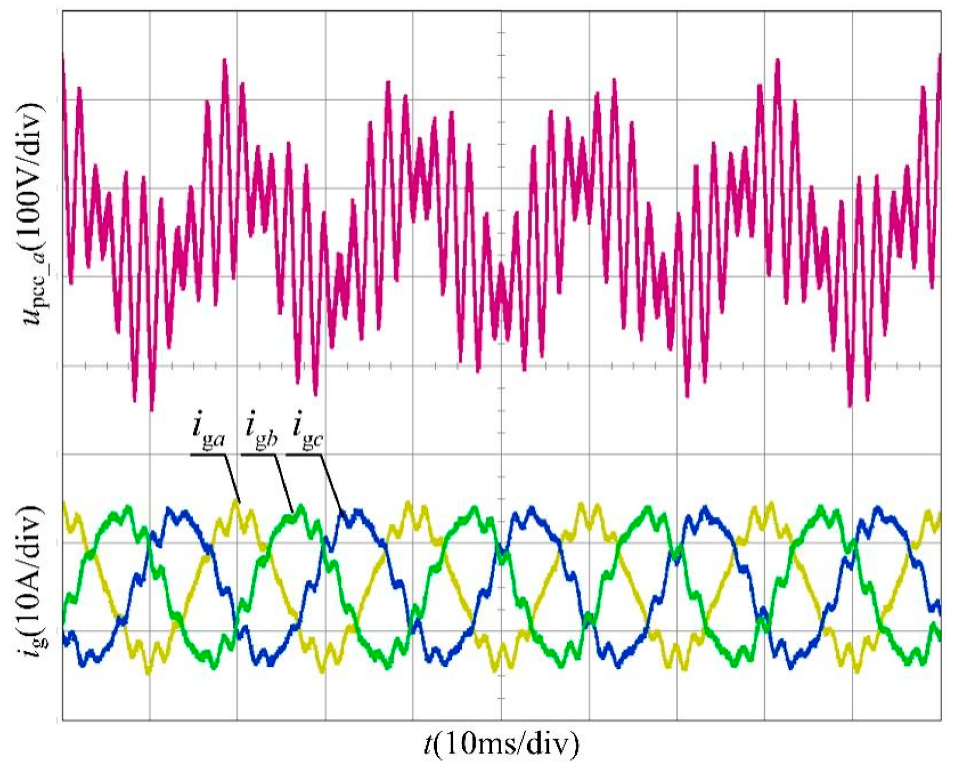
With the grid impedance increased to Lwg = 6.5 mH, Figure 20 displays the experiment results for upcc_a and ig when utilizing the traditional PLL. It is evident that the GCC with the traditional PLL experiences significant oscillations under these conditions.
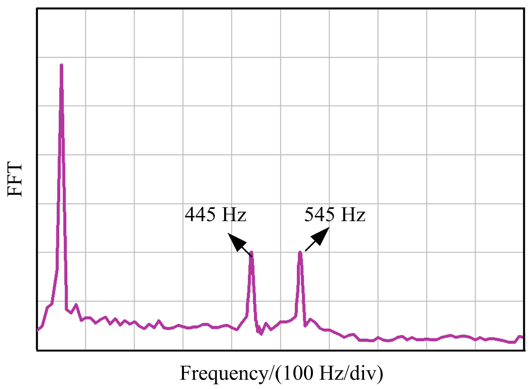
A Fourier spectrum analysis of the output current was conducted, depicted in Figure 21. It is evident that the unstable frequency of ig mainly concentrates at 445 Hz and 545 Hz, which aligns with the findings in Figure 6 and Figure 15. This further affirms the accuracy of the theoretical investigation.
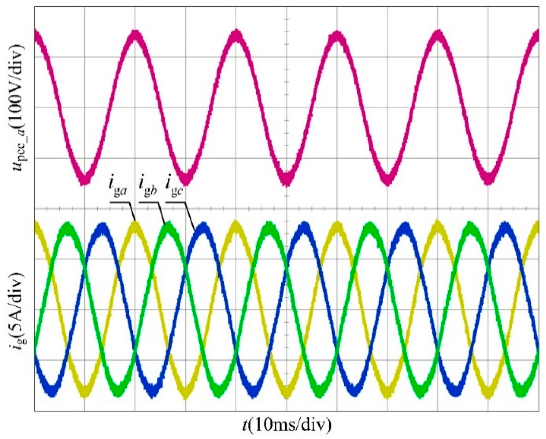
This paper introduces the SOGI-PLL as a solution to mitigate the PLL-FCE, thereby enhancing the operation stability of GCCs under weak grid conditions. In Figure 22, the steady-state experiment results for upcc_a and ig are depicted when employing the SOGI-PLL with Lwg = 6.5 mH. It was found that the oscillations in the output current have been significantly mitigated when applying the SOGI-PLL, indicating its effectiveness in suppressing the PLL-FCE and ensuring the system operates stably.
The above phenomenon in Figure 22 can be explained as follows: With the enhancement of the voltage harmonic filtering ability during OSG signal extraction, the stability of the grid-connected system under a weak current network is gradually improved, that is, the adverse effect of frequency coupling on the grid-connected system can be weakened by enhancing the filtering ability of the PLL pre-filter.
The analysis of the simulation and experiment results shows that the asymmetrical control of the PLL introduces FCEs, and it negatively impacts the quality of the output current waveform under voltage harmonic disturbances. As grid impedance increases, the FCE intensifies, causing issues with its interaction with both the grid and the output impedance of the GCC. This can endanger the stable operation of the converter under weak grid circumstances. The SOGI-PLL designed in this paper efficiently inhibits the FCE and reduces its impact on the output impedance of the GCC, thereby improving oscillations in the output current and ensuring stable running of GCCs even in the presence of high grid impedance.

6. Conclusions

The PLL-FCE induces significant distortion in the grid-connected current during PCC harmonic disturbances via coupling admittance. As the grid impedance rises, the ability of the GCC to run steadily diminishes, leading to low-frequency oscillations. This paper investigates the impact of the FCE on GCC stability by developing an output impedance model that incorporates PLL frequency coupling characteristics. Additionally, it presents an optimized control scheme to address these stability concerns. The following conclusions are drawn:
(1)
The analysis of the coupling admittance modeling reveals that the PLL-FCE significantly impacts the output impedance characteristics of the GCC, particularly in the range of medium and low frequency.
(2)
The impedance of the GCC is influenced not only by the coupling admittance but also by the grid impedance, particularly through the PLL-FCE. As the grid impedance increases, the coupling effect becomes more pronounced. The interplay between these factors shapes a negative impact on the overall performance and stability of the converter system and increases the risk of its instability.
(3)
The SOGI-PLL introduced in this paper serves to mitigate coupling admittance, thereby effectively suppressing the PLL-FCE. As the grid impedance escalates, this approach can ameliorate system instability stemming from PLL-FCEs.

Author Contributions

Conceptualization, Y.Z.; methodology, Y.Z. and H.P.; text editing, correction, X.Z.; numerical simulation, Y.Z. and H.P.; engineering experiments, Y.Z.; normal analysis, writing—preparation of the original manuscript, Y.Z. and X.Z.; writing—review and editing, Y.Z., H.P. and X.Z. All authors have read and agreed to the published version of the manuscript.

Funding

This research was funded by the Natural Science Foundation of Tianjin (19JCQNJC06000), the National Natural Science Foundation of China (52304088) and Research on multi-platform code automatic generation technology of EtherNet/IP communication application layer (2023-TD-ON007).

Data Availability Statement

Data are contained within the article.

Conflicts of Interest

The authors declare no conflicts of interest.

References

  1. Whazaei, J.; Tu, Z.; Asrari, A.; Liu, W. Feedback linearization control of converters with LCL filter for weak AC grid integration. IEEE Trans. Power Syst. 2021, 36, 3740–3750. [Google Scholar]
  2. Negri, S.; Ubezio, G.; Faranda, R.S. Fault-Tolerant Multiport Converter for Hybrid Distribution Systems: Configuration, Control Principles and Fault Analysis. Appl. Sci. 2024, 14, 4024. [Google Scholar] [CrossRef]
  3. Wang, X.; Blaabjerg, F. Harmonic stability in power electronic-based power systems: Concept, modeling, and analysis. IEEE Trans. Smart Grid 2019, 10, 2858–2870. [Google Scholar] [CrossRef]
  4. Sun, J.; Wang, G.; Du, X.; Wang, H. A theory for harmonics created by resonance in converter-grid systems. IEEE Trans. Power Electron. 2019, 34, 3025–3029. [Google Scholar] [CrossRef]
  5. Golestan, S.; Guerrero, J.M.; Vasquez, J.C. Three-phase PLLs: A review of recent advances. IEEE Trans. Power Electron. 2017, 32, 1894–1907. [Google Scholar] [CrossRef]
  6. Hu, Q.; Fu, L.; Ma, F.; Ji, F. Large signal synchronizing instability of PLL-based VSC connected to weak AC grid. IEEE Trans. Power Syst. 2019, 34, 3220–3229. [Google Scholar] [CrossRef]
  7. Chen, J.; Zhu, S.; Li, H.; Zhong, C. An Optimized method of PLL for grid-connected inverter in the weak grid. Chin. J. Sci. Instrum. 2022, 43, 234–243. [Google Scholar]
  8. Wu, W.; Zhou, L.; Chen, Y.; Luo, A.; Dong, Y.; Zhou, X.; Xu, Q.; Yang, L.; Guerrero, J.M. Sequence-impedance-based stability comparison between VSGs and traditional grid-connected inverters. IEEE Trans. Power Electron. 2019, 34, 46–52. [Google Scholar] [CrossRef]
  9. Wang, Y.; Chen, X.; Zhang, Y.; Chen, J.; Gong, C. Frequency characteristics analysis and stability research of phase locked loop for three-phase grid-connected inverters. Proc. CSEE 2017, 37, 3843–3853. [Google Scholar]
  10. Nian, H.; Xun, Y.; Chen, L.; Li, G. Frequency coupling characteristic modeling of grid-connected inverter and system stability analysis. Proc. CSEE 2019, 39, 1421–1431. [Google Scholar]
  11. Wang, X.; Harnefors, L.; Blaabjerg, F. Unified impedance model of grid-connected voltage-source converters. IEEE Trans. Power Electron. 2018, 33, 1775–1787. [Google Scholar] [CrossRef]
  12. Li, Z.; Tang, X.; He, Y.; Liu, P.; Li, X. Admittance reshaping method of converter for suppressing background harmonic of grid. Proc. CSEE 2024, 44, 704–713. [Google Scholar]
  13. Gong, H.; Wang, X.; Harnefors, L. Rethinking current controller design for PLL-synchronized VSCs in weak grids. IEEE Trans. Power Electron. 2022, 37, 1369–1381. [Google Scholar] [CrossRef]
  14. Tang, X.; Li, Z.; Li, Y.; He, Y. Frequency coupling oscillation analysis and decoupling control design of grid connected converter. Proc. CSEE 2023, 43, 3127–3136. [Google Scholar]
  15. Guan, W.; Li, H.; Liu, Y.; Xu, M.; Chen, X.; Rong, S.; Song, B. Low-frequency coupling resonance suppression method of PLL-based current controlled converter based on coordinated control. In Proceedings of the 2022 IEEE 2nd International Conference on Power, Electronics and Computer Applications (ICPECA), Shenyang, China, 21–23 January 2022; pp. 1151–1157. [Google Scholar]
  16. Xiao, S.; Xu, L. Analysis of key factors and suppression measures for sub-synchronous oscillation of direct-drive PMSG based on frequency coupled impedance. Power Syst. Technol. 2023, 47, 1641–1652. [Google Scholar]
  17. Wu, X.; Wang, Y.; Chen, X.; Chen, J.; He, G.; Li, G. Sequence impedance model and interaction stability research of three-phase grid-connected inverters with considering coupling effects. Proc. CSEE 2020, 40, 1605–1616. [Google Scholar]
  18. Xu, J.; Bian, S.; Qian, Q.; Qian, H.; Xie, S. Robustness improvement of single-phase inverters under weak grid cases by adding grid current feed-forward in delay-based phase-locked loop. IEEE Access 2020, 8, 124275–124287. [Google Scholar] [CrossRef]
  19. Zhang, X.; Fu, S.; Chen, W.; Zhao, N.; Wang, G.; Xu, D. A symmetrical control method for grid-connected converters to suppress the frequency coupling under weak grid conditions. IEEE Trans. Power Electron. 2020, 35, 13488–13499. [Google Scholar] [CrossRef]
  20. Lin, X.; Yu, R.; Yu, J.; Wen, H. Constant-coupling-effect-based PLL for synchronization stability enhancement of grid-connected converter under weak grids. IEEE Trans. Ind. Electron. 2023, 70, 11310–11323. [Google Scholar] [CrossRef]
  21. Yang, D.; Wang, X.; Liu, F.; Xin, K.; Liu, Y.; Blaabjerg, F. Symmetrical PLL for SISO impedance modeling and enhanced stability in weak grids. IEEE Trans. Power Electron. 2020, 35, 1473–1483. [Google Scholar] [CrossRef]
  22. Li, J.; Ding, J.; Chai, T.; Lewis, F.; Jagannathan, S. Adaptive interleaved reinforcement learning: Robust stability of affine nonlinear systems with unknown uncertainty. IEEE Trans. Neural Netw. Learn. Syst. 2024, 33, 270–280. [Google Scholar] [CrossRef] [PubMed]
  23. Li, H.; Wang, S.; Shi, H.; Wang, L.; Su, C.; LI, P. Robust asynchronous fuzzy predictive fault-tolerant tracking control for nonlinear multi-phase batch processes with time-varying reference trajectories. Eng. Appl. Artif. Intell. 2024, 133, 108415. [Google Scholar] [CrossRef]
  24. Shi, H.; Zuo, L.; Wang, S.; Yuan, Y.; Su, C.; Li, P. Robust predictive fault-tolerant switching control for discrete linear systems with actuator random failures. Comput. Chem. Eng. 2024, 181, 108554. [Google Scholar] [CrossRef]
  25. Wang, G.; Du, X.; Shi, Y.; Tai, H.; Ji, Y. Mechanism analysis and stabilization of three-phase grid-inverter systems considering frequency coupling. J. Power Electron. 2018, 18, 853–862. [Google Scholar]
  26. Zou, X.; Du, X.; Wang, G.; Yang, Y.; Ji, Y. The single equivalent inverter admittance model of three-phase grid-connected inverter system considering frequency coupling. In Proceedings of the IECON 2017—43rd Annual Conference of the IEEE Industrial Electronics Society, Beijing, China, 29 October–1 November 2017; pp. 4994–4999. [Google Scholar]
  27. Zhang, Y.; Tian, M.; Zhang, H.; Song, J.; Zhang, W. Admittance modeling and stability enhancement of grid-connected inverter considering frequency coupling in weak grids. Electr. Power Syst. Res. 2022, 209, 108034. [Google Scholar] [CrossRef]
Figure 1. Frequency relationship of Δup and Δiαβ.
Energies 17 03438 g001
Figure 2. Control diagram of the LCL−type GCC.
Energies 17 03438 g002
Figure 3. Bode diagrams of Yc(s) and Ys(s).
Energies 17 03438 g003
Figure 4. Bode diagrams of Zs(s), ZFCE(s) with different grid impedances.
Energies 17 03438 g004
Figure 5. Nyquist curves of Top0(s) and Top(s).
Energies 17 03438 g005
Figure 6. Bode diagrams of Zwg(s) and ZFCE(s) with Lwg = 6.5 mH. (a) Bode diagrams of Zwg(s) and ZFCE(s) when Lwg = 6.5 mH. (b) A zoomed-in portion of the Bode diagrams illustrating Zwg(s) and ZFCE(s) when Lwg = 6.5 mH.
Energies 17 03438 g006
Figure 7. The structure of the SOGI−PLL.
Energies 17 03438 g007
Figure 8. The schematic diagram of SOGI.
Energies 17 03438 g008
Figure 9. Bode diagram of D(s).
Energies 17 03438 g009
Figure 10. Nyquist curves of Top(s) and Top1(s) when Lwg = 6.5 mH.
Energies 17 03438 g010
Figure 11. Simulation results for upcc and ig under 20 Hz voltage perturbation with SRF−PLL (Lwg = 3.2 mH).
Energies 17 03438 g011
Figure 12. Frequency spectrum of ig under 20 Hz voltage perturbation with SRF−PLL (Lwg = 3.2 mH).
Energies 17 03438 g012
Figure 13. Simulation results for upcc and ig employing SRF−PLL (Lwg = 3.2 mH).
Energies 17 03438 g013
Figure 14. Simulation results for upcc and ig using SRF−PLL (Lwg = 6.5 mH).
Energies 17 03438 g014
Figure 15. Harmonic spectrum of ig employing SRF−PLL when Lwg = 6.5 mH.
Energies 17 03438 g015
Figure 16. Transient results for upcc and ig using the proposed SOGI−PLL (Lwg = 6.5 mH).
Energies 17 03438 g016
Figure 17. Experiment platform.
Energies 17 03438 g017
Figure 18. Experiment results for upcc_a, ig and FFT of ig under 20 Hz voltage perturbation with SRF−PLL when Lwg = 3.2 mH.
Energies 17 03438 g018
Figure 19. Experiment results for upcc_a and ig utilizing SRF−PLL when Lwg = 3.2 mH.
Energies 17 03438 g019
Figure 20. Experiment results for upcc_a and ig utilizing SRF−PLL (Lwg = 6.5 mH).
Energies 17 03438 g020
Figure 21. FFT of ig utilizing SRF−PLL (Lwg = 6.5 mH).
Energies 17 03438 g021
Figure 22. Experiment results for upcc_a and ig applying SOGI−PLL with Lwg = 6.5 mH.
Energies 17 03438 g022
Table 1. Parameters of three-phase GCC.
ParameterNotationValue/Unit
CapacityS4.0 kVA
DC sourceVdc400 V
InductanceLwg3.2/6.5 mH
PCC voltageupcc110 V
Disclaimer/Publisher’s Note: The statements, opinions and data contained in all publications are solely those of the individual author(s) and contributor(s) and not of MDPI and/or the editor(s). MDPI and/or the editor(s) disclaim responsibility for any injury to people or property resulting from any ideas, methods, instructions or products referred to in the content.