1. Introduction
In an effort to raise the power and efficiency of advanced gas turbines, the turbine inlet temperature is growing higher and higher over the years. For heavy-duty gas turbines, the turbine inlet temperature could reach 1700 K and even higher. However, the melting point of blade materials is far below the operating temperature; thus, protective methods like thermal barrier coatings, blade-cooling technology, and advanced blade materials are widely used for advanced gas turbines. Actually, for every 20 K increase in turbine inlet temperature, about 8 K comes from the progress of blade material, while 12 K comes from the improvement of blade-cooling technology [
1]. Therefore, the research on sufficient cooling methods for turbine blade-cooling systems is still of good theoretical and practical importance for developing advanced gas turbines.
Through the years, the cooling methods have developed from simple inner cooling to complex cooling, including multiple inner cooling methods and outer film cooling [
2]. Hedlund et al. [
3,
4,
5] conducted a significant amount of work on the swirl cooling structure with one chamber. Their work has promoted subsequent research. Rao et al. [
6,
7] studied the swirl flow in a multi-nozzle model. In terms of swirl cooling with one chamber, Seibold et al. [
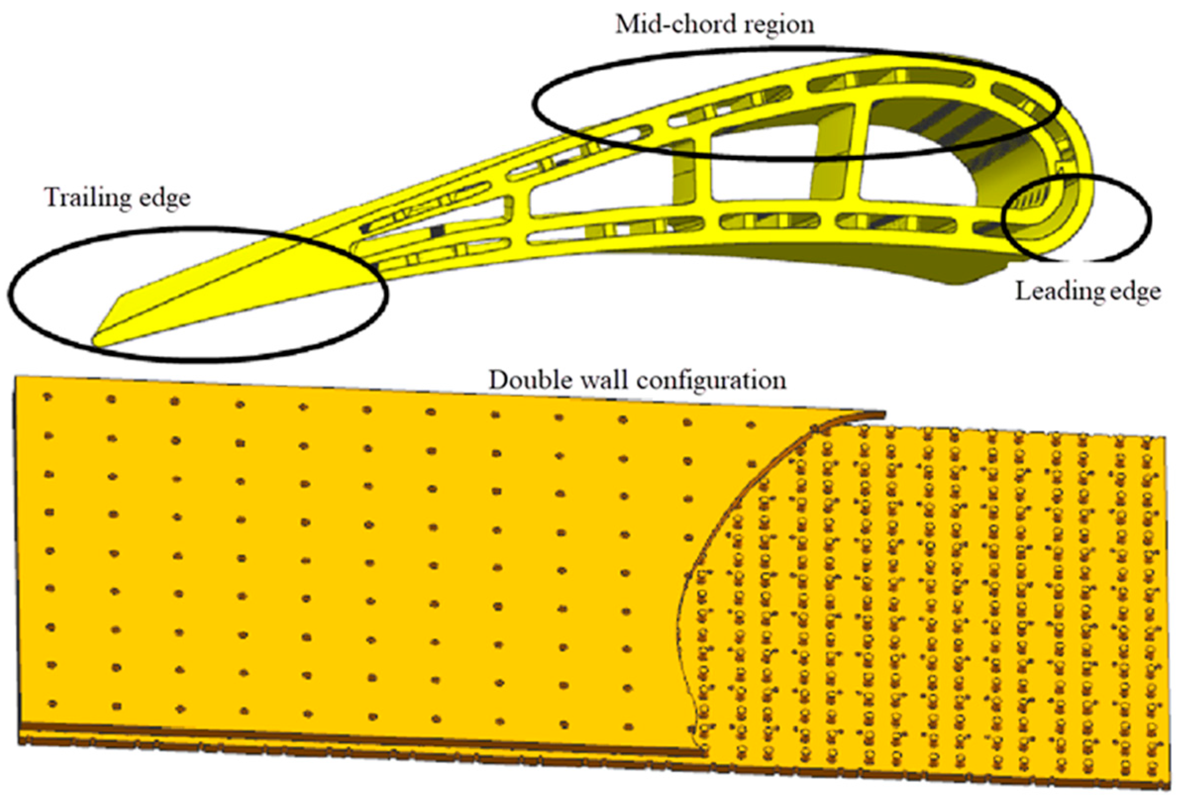
8] performed a comprehensive review on the basic flow features of swirl tubes. With the process of casting technology, the Lamillory or double-wall cooling method has been researched and applied. Double-wall cooling could provide better heat protection with less coolant consumption due to its special double-walls with a microchannel inside, as shown in
Figure 1. Bunker at al. [
9] pointed out that small cooling channels are casted in the local positions, and the coolant used by the internal impingement cooling can cool the blade again so as to benefit to the heat transfer. This new double-cooling concept is very different to the traditional cooling methods, and it has been applied in actual blade-cooling systems by companies like Allison, GE, and Siemens. The double-wall concept is known as the next generation of cooling technology.
Most of the studies on the double-wall cooling was based on bilayer plates. Gillespie et al. [
10] used an engine wall cooling geometry to study the impingement cooling behavior. Li et al. [
11] compared the cooling performance of three double-layer wall cooling structures: only impact cooling, only film cooling, and a combination of impact/film cooling. The research results suggest that the impact/film double-layer wall cooling with rib structure had the best cooling performance. Liu et al. [
12] used an infrared thermal imager to experimentally study the relationships between various Biot numbers and gas film hole diameters on the cooling performance of a flat ribbed double-layer wall structure. Liu et al. [
13] constructed a flat double-layer wall-cooling structure with impact holes and film holes and systematically studied the effects of blowing ratio, arrangement of impact holes, and wall thickness on the cooling performance. Murray et al. [
14] established a new, experimental heat transfer device to study double-layer walls’ cooling behavior. Based on the impact double-layer wall cooling structure with gas film holes, the overall cooling efficiency was obtained using an infrared thermal imager. Li et al. [
15] investigated the cooling characteristics of blades with double-layer walls and found that the efficiency in the middle region of the leading edge was better than that in the root and top regions. Wright et al. [
16] set up a concave double-layer wall cooling structure based on the actual blade shape. The simplified structure of this cooling structure was vortex/impact composite cooling. This study showed the presence of local high-heat-transfer -intensity zones on large concave surfaces with curvature. Yang et al. [
17] studied the effect of different connection and geometry parameters on double-wall plates. The results showed that the linked jets could enhance the local heat transfer. Rogers et al. [
18] conducted experiments to research the double-wall impingement/film cooling. The aerodynamic parameters of blowing ratios and the Reynolds number were studied. In terms of the film hole parameters, Zhang et al. [
19], Rao et al. [
20,
21,
22] and Vanga et al. [
23] studied the impact of the film hole, angle, spacing and arrangement, louver film hole, and other parameters. The results show that a reasonable film hole arrangement can effectively increase the cooling efficiency and reduce the flow resistance.
From above discussion, it can be found that most structures established to study double-wall cooling are derived from flat plates. However, the actual turbine blade, especially the leading edge, consists of curved surfaces. Until now, few scholars have focused their research on curved double-wall cooling. Furthermore, the leading edge requires more efficient cooling methods than other regions; most studies on leading-area cooling are focused on impingement cooling coupled with film holes. These cooling methods have the limitations of bad uniformity and large coolant air consumption. Thus, new cooling methods for the leading edge need to be explored. However, few reports have been given.
The authors are working on a new cooling method for blades at high temperature levels, especially for leading edge regions. In this paper, we proposed another structure combining vortex flow and double-wall flow, and the research showed that it could provide very good protection with high heat transfer intensity [
24]. As a series of studies, this paper makes an exploration of a variation of double-wall vortex cooling structure for advanced blade cooling. The authors hope the study can contribute to the research and development of blade-cooling technology.
2. Configuration Establishment and Research Cases
The double-wall vortex cooling structure established in the study is mainly applicable to a turbine blade leading edge with large surface curvature. With the development of advanced casting technology and 3D printing technology, we can manufacture turbine blades with very small channels. Therefore, the configurations established in this paper can be easily manufactured.
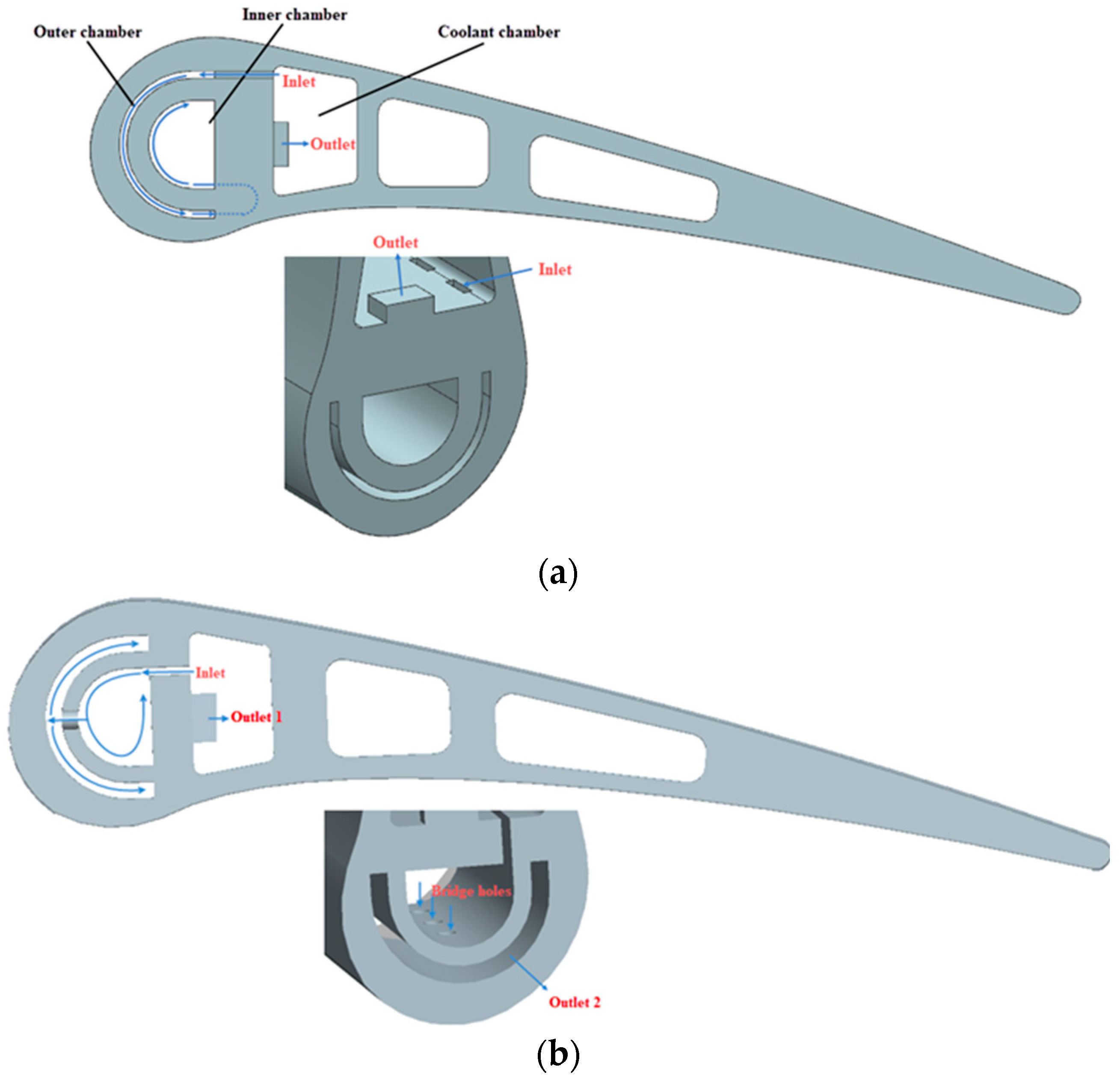
Figure 2 presents a diagrammatic sketch on how the two kinds of double-wall vortex cooling structures are implanted in blades. The chamber length is 60 mm, the basis nozzle length and width are 4 mm and 1 mm, the distance of adjacent nozzles is 8 mm, the diameter of the inner and outer chambers are 12 mm and 20 mm, and the thickness of the outer chamber is 1 mm.
Generally, the two configurations consist of tangential inlet nozzles, a semi-cylinder-like inner chamber, an externally wrapped curved outer chamber, and a rectangular exit. The main difference between the two configurations is how the inner chamber and outer chamber are connected. In this paper, the U-shape passages are used for connection so that vortex flow can be generated in both chambers. In our previous study, the bridge holes were used for connection. In this way, the vortex flow is only generated in the internal chamber while the external chamber is actually impingement cooling. In conclusion, the configuration established in this paper is a variation of the double-wall vortex cooling structure which can improve the double-wall cooling behavior.
Four groups of cases were researched to better understand this variation structure. The researched cases are listed in
Table 1. The cases mainly focused on the influences of nozzle geometry. Firstly, this new double-wall vortex cooling configuration is compared with the original one published in [
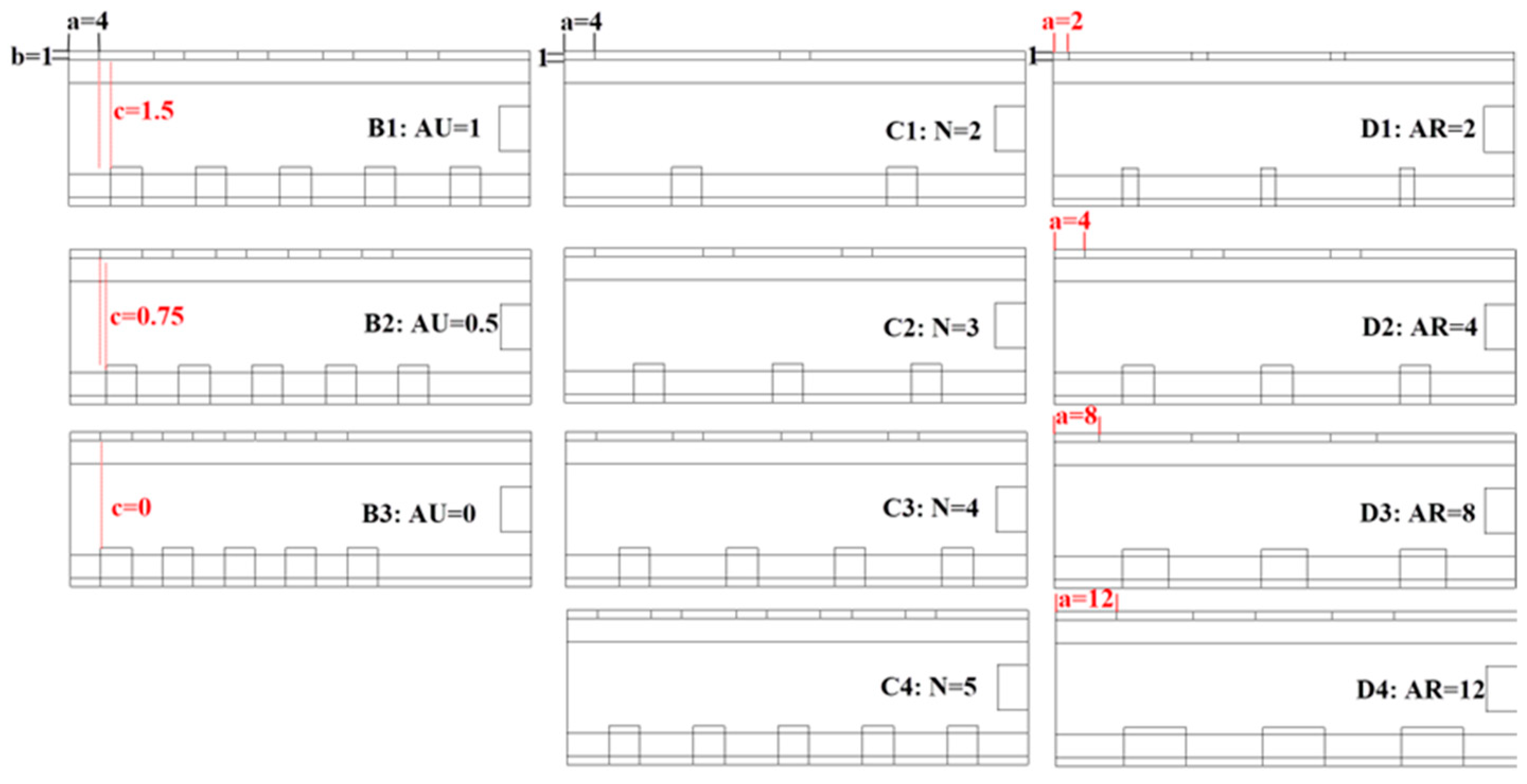
24] to evaluate its potential. Then, the influences of axial uniformity (AU), number (N), and aspect ratio (AR) are further explored based on the variation configuration. The geometrical structures are presented in
Figure 3 and
Figure 4.
The axial uniformity (AU) is defined to evaluate whether the nozzles are uniformly arranged along the axial direction. The definition is:
Here, c is the gap distance between the adjacent nozzle and U-shape passage, and c0 represents the maximum distance when the nozzles are arranged to the greatest extent. Thus, the absolute value of c0 is different for various groups, and the c0 of group B in this paper is 1.5 mm. As the AU changes from 0 to 1, the nozzle is more uniformly arranged along the axial direction.
The nozzle number (N) various from 2 to 5 in this paper. The aspect ratio (AR) is defined to study the influences of nozzle cross section geometry. The definition is:
Here, a is the length of the nozzles and b is the width of the nozzles.
3. Numerical Method
3.1. Mesh Generation
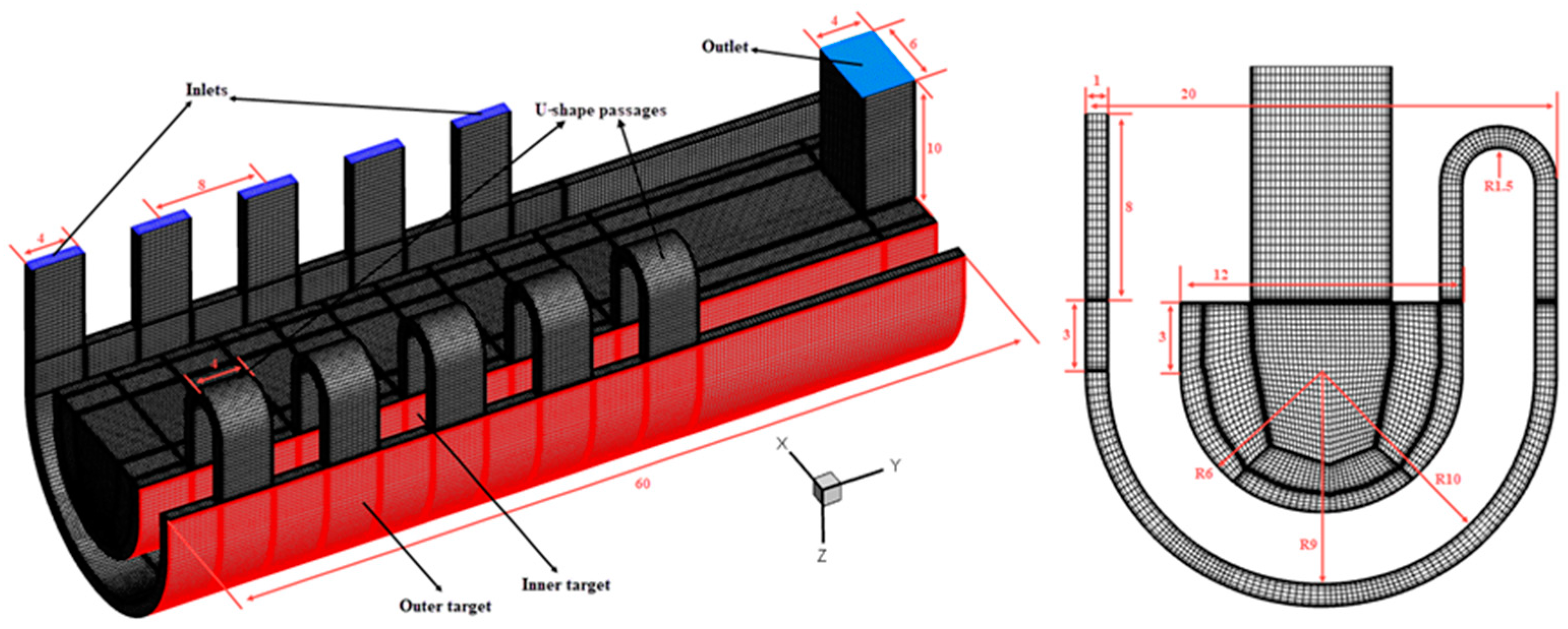
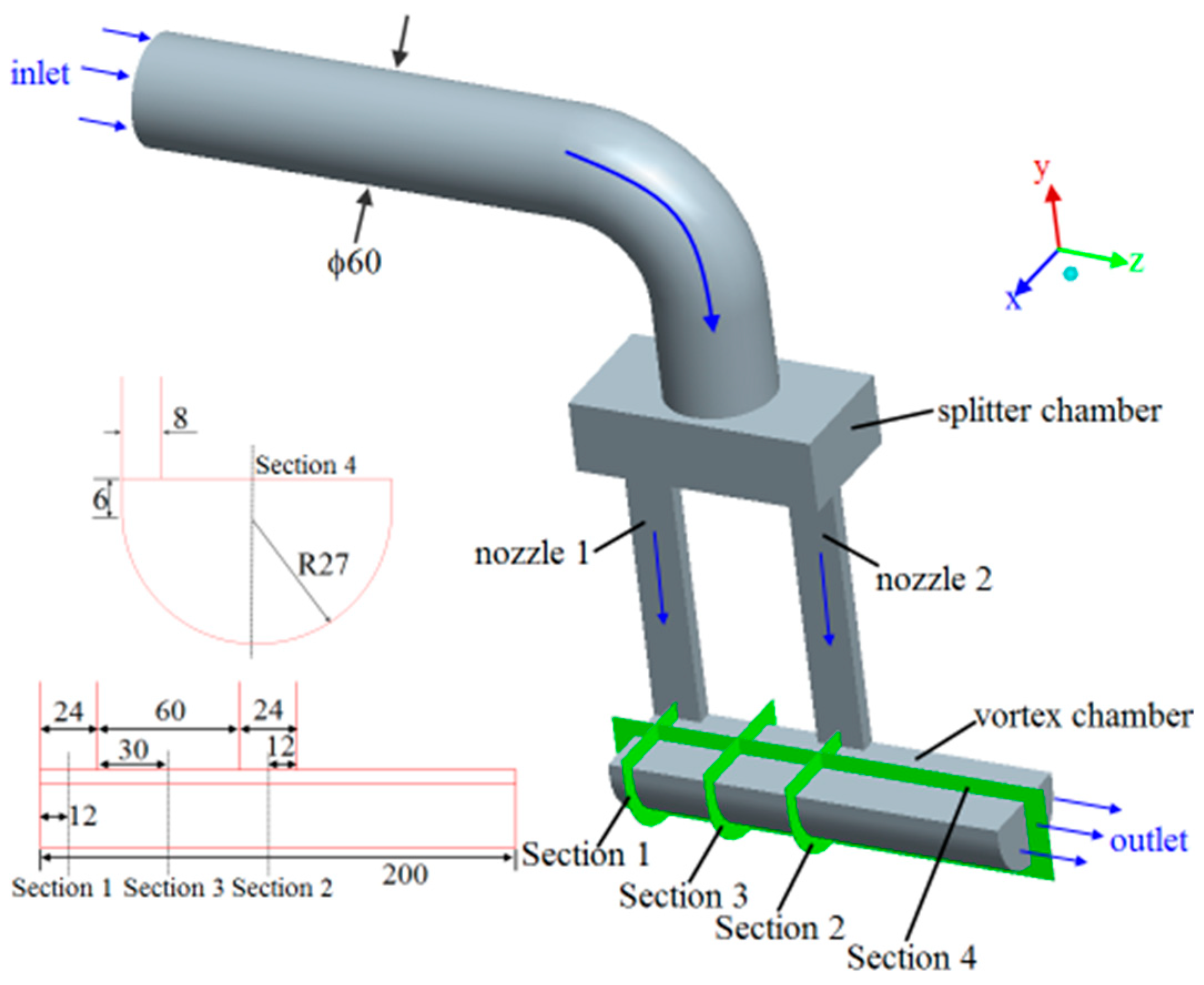
Figure 5 gives the mesh generation and geometrical dimensions. The inlet nozzles with sizes of 4 mm × 1 mm connect with the outer chamber to generate vortex flow, while the U-shaped passages are the linkage between inner chamber and outer chamber to generate vortex flow. The grids are generated by ICEM with mesh y
+ < 1. C-type mesh grids are utilized for the inner and outer chambers, and O-type mesh grids are used for the rest.
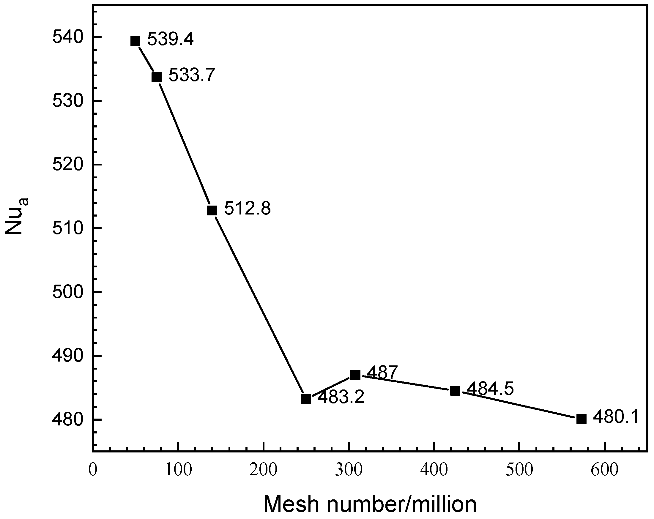
An analysis of grid independence was conducted, and the result is shown in
Figure 6. As the mesh number increased to 250 million, the averaged Nusselt number hardly changed. The chosen mesh number of all cases was larger than 250 million, and it met the numerical calculation requirement.
3.2. Solution Method and Boundary Conditions
The software ANSYS CFX 14.5 was applied to solve the 3D viscous steady Reynolds averaged Navier–Stokes (RANS) equations. For the detailed theoretical model and computational convergence algorithm, refer to the cited papers [
25,
26]. During the calculation, when the residuals of pressure, monument, velocity, and the globally-averaged Nusselt number are lower than 10
−5, we regard the results as convergent and accurate enough.
For the boundary conditions, the coolant was set as air ideal gas, which is often used for steady-state flow and heat transfer problems. The flow mass and temperature were given as the inlet boundaries, at 24.8 kg/h and 77 °C. The pressure boundary, which is 110 kPa, was set for the outlet. The constant temperature boundary was set for the targets at 227 °C.
3.3. Turbulence Model Validation
Turbulence model validation is necessary for numerical simulations. According to recent research, the pattern of flow structures is the key factor to the choice of turbulence model. The flow with large-scale swirl was the main flow pattern in the double-wall vortex cooling; thus, the turbulence model validation was conducted based on vortex cooling from the view of flow performance validation as well as heat transfer performance validation.
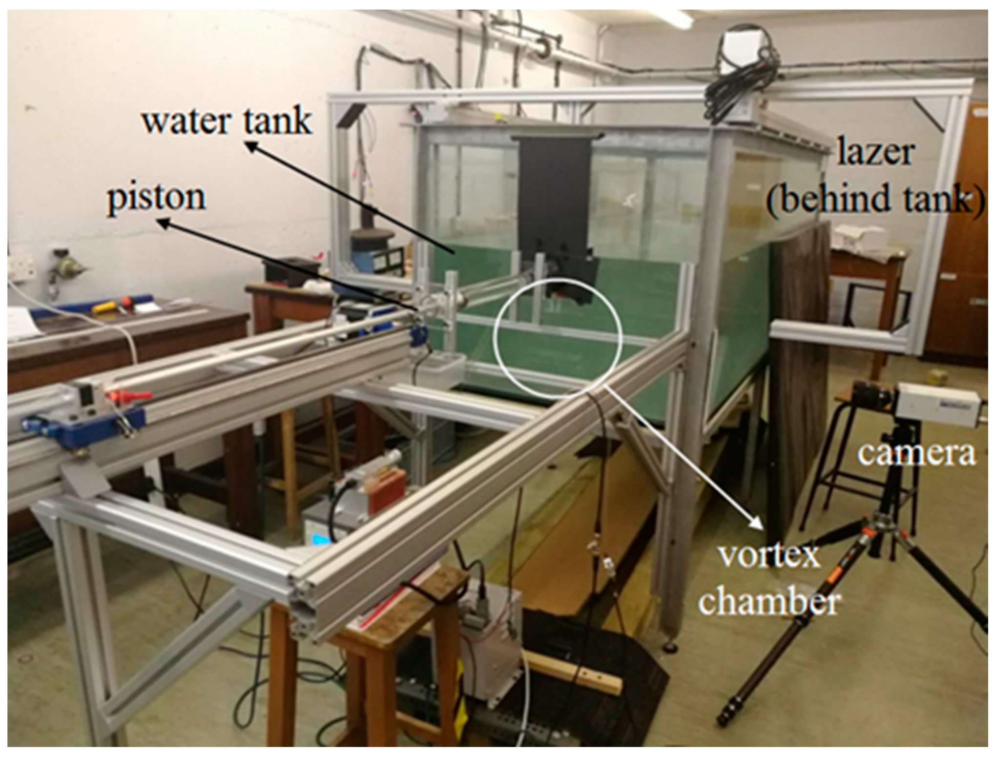
Flow performance validation was conducted in a semi-cylinder vortex flow chamber using PIV technology, as shown in
Figure 7. The validation configuration was a single vortex cooling chamber with two nozzles, as shown in
Figure 8. The details of the experiment are referenced in our previous work [
27]. In the water, the glass spheres were set as tracer particles. The testing sheets were illuminated by a laser. The images were obtained using a CCD camera (Sensicam, PCO, Kelheim, Germany). The water velocity changed from 125 mm/s to 500 mm/s to generate three Reynolds numbers of 5000, 10,000, and 20,000. The water temperature was 18 °C, and the whole setup was under atmospheric pressure and at room temperature. The case when the inlet Reynolds number was 10,000 was selected, and the velocity on plane 1 was used for validation.
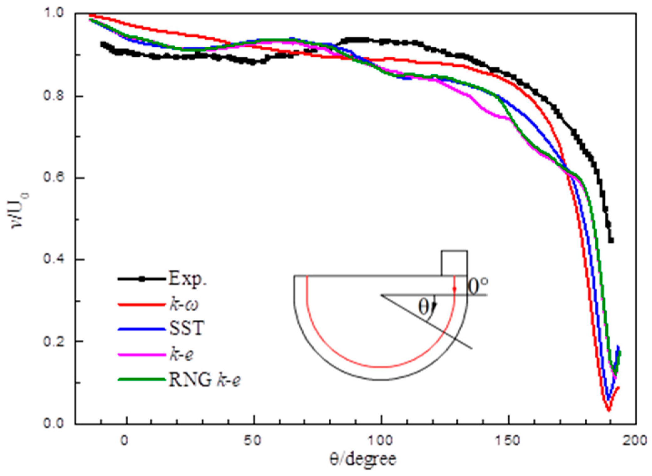
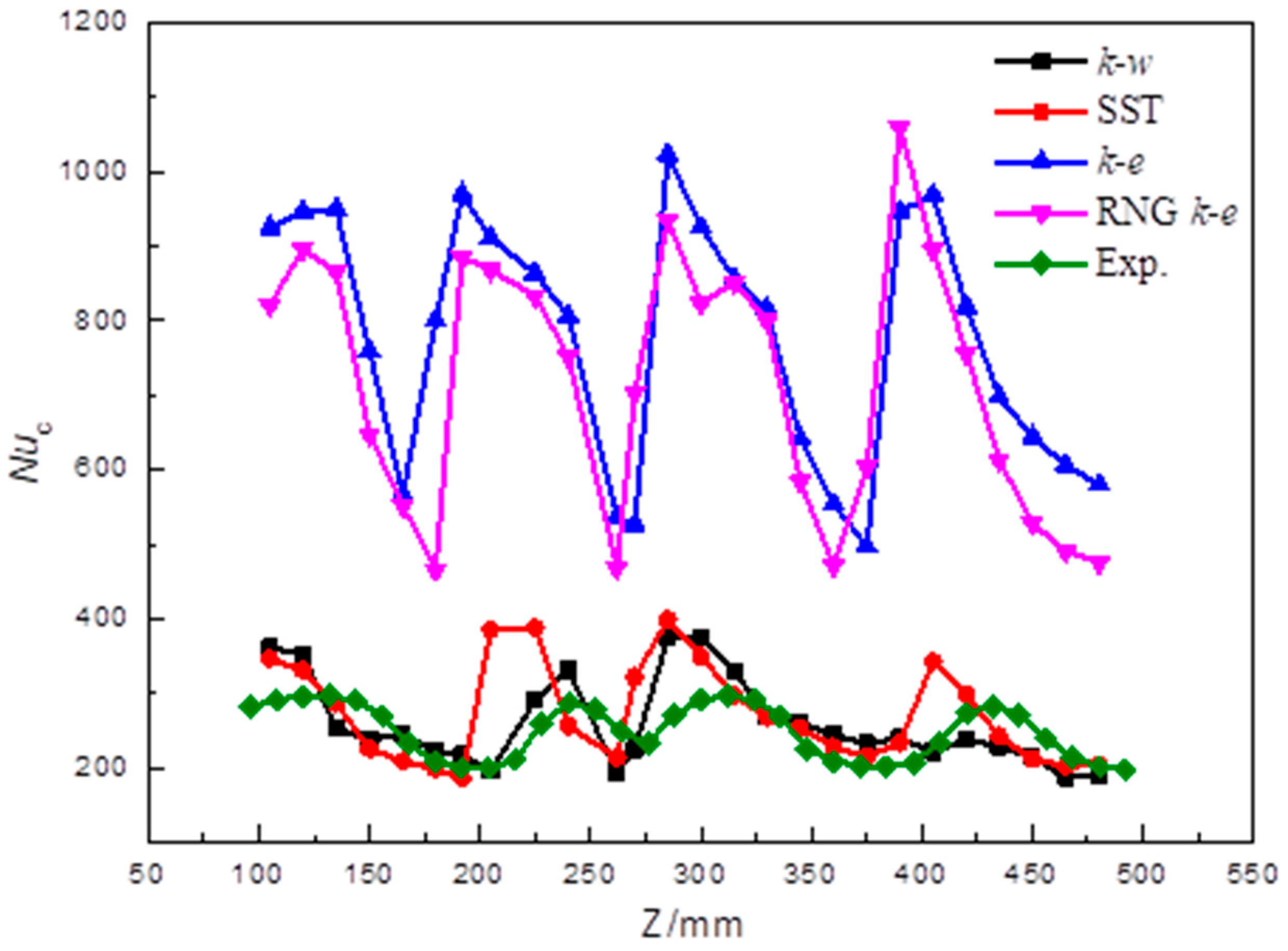
Different turbulence models were chosen, and the validation results are presented in
Figure 9. Generally, the standard
k-
ω turbulence model has the highest prediction accuracy, with a calculation error of about 8% compared to the other three models. Secondly, the heat transfer performance validation was carried out in a similar semi-cylinder vortex cooling chamber using infrared thermography, and the details are given in [
28]. Also, four models of
k-
ε, RNG
k-
ε, standard
k-
ω, and SST
k-
ω were chosen for validation. The circumferential-averaged Nusselt number along the longitude direction is given in
Figure 10. The standard
k-
ω and SST
k-
ω had higher prediction accuracy than the
k-
ε and RNG
k-
ε models.
In terms of the vortex cooling configuration, the numerical calculation method with the standard k-ω turbulence model proved to have good accuracy, with an acceptable prediction error. Considering that no experiments involving double-wall vortex cooling configuration could be found and that the main flow patterns of both cooling methods were consistent, it was reasonable to apply the numerical calculation method with the standard k-ω turbulence model to the numerical simulation.
4. Discussion
The flow condition, pressure distribution, and heat transfer intensity were mainly analyzed to estimate the cooling characteristics, and each evaluation parameter was defined as follows:
Total pressure loss
η is calculated by:
where P
ti is the inlet total pressure and P
to is the outlet total pressure.
Nusselt number
Nu is used to characterize the heat transfer intensity:
where q
w is the heat flow density at the target surface; D
1 is the hydrodynamic diameter of the cyclonic cavity cross-section; T
w is the target surface temperature; λ is the thermal conductivity coefficient;
Nua is the globally-averaged Nusselt number, and
Nu∞ is the fully developed heat transfer intensity of the flow in the cyclone-free tube using the Dittus–Boelter heat transfer correlation equation.
The dimensionless flow resistance coefficient
f is defined to describe the pressure loss:
where P
si is the inlet static pressure; ρ is the density of the cold gas; U is the inlet average velocity; L is the length of the lumen; and
f∞ is the flow resistance coefficient of the flow in the fully-developed cyclotron-free tube, calculated using the Blasius drag coefficient equation.
We defined the integrated heat transfer factor
j to comprehensively evaluate the flow and heat transfer characteristics:
4.1. Comparison of Two Different Double-Wall Vortex Cooling Configurations
Figure 11 shows the streamlines of two different double-wall vortex cooling configurations. In terms of the variant configuration, the coolant air firstly entered into the outer chamber to form a vortex flow. Then, it tangentially flowed into the inner chamber through U-shaped passages. The flow in the outer chamber was smoother along the outer wall, which is similar to a vortex flow. These U-shape passages connected the inner and outer chambers and formed two kinds of vortex flows in both chambers. Comparatively, the vortex flow was only generated in the internal chamber in terms of the original double-wall vortex cooling configuration. In this way, the inner chamber was cooled by the vortex cooling while the outer chamber was cooled by the impingement cooling. As can be seen, the coolant velocity in the external chamber of A1 was larger than that in A2, which means the outer target may have had higher heat transfer intensity. In the actual operating situation for a gas turbine, the outer chamber would need more efficient cooling than the inner chamber, so the variant double-wall vortex cooling configuration with better streamline distribution would be more suitable for the leading edge.
Furthermore, the
Nu contours on inner target and outer target of both configurations are given in
Figure 12. The curved targets were reconstructed to 2D planes.
In case A1, both targets presented the vortex cooling distribution with five high Nu stripes. On the outer target, the Nu stripes showed an S route along the circumferential direction because of the limited outer chamber space and the staggered arrangement of nozzles and U-shaped passages. In case A2, only the inner target presented typical vortex cooling, and the high Nu region was larger than that in case A1. The Nu distribution on outer target of A2 presented the characteristics of impingement cooling, and the Nu region was much smaller than that of A1. Generally speaking, the Nu distribution results of both configurations show that the original configuration had a better Nusselt number distribution with a higher value and a larger area, which demonstrated its advantages in terms of inner surface heat transfer performance. Meanwhile, the heat transfer performance on the outer chamber in the new variant configuration improved significantly in terms of heat transfer intensity and uniformity, which shows its advantages in outer surface heat transfer performance.
Table 2 gives a comparison of the quantitative parameters between two cases. Generally, the variation has a higher total pressure loss and friction loss than the origin. In addition, the inner averaged Nusselt number of A1 was 27% lower than A2, which means the heat transfer performance was worse for the variation configuration. However, we noticed that the heat transfer performance on the A1 outer target showed significant improvement over A2, and the averaged Nusselt number was 106% larger. And the globally averaged Nusselt number of A1 was also 17.1% higher than A2. This suggests that the new double-wall vortex cooling configuration can provide better cooling protection than the original one for the blade’s leading edge. In particular, the outer target showed worse hot gas crush, and it would require more efficient cooling method. In this way, the variation configuration is a good improvement compared to the original one.
Based on the variation double-wall vortex cooling configuration, the influences of the nozzles’ geometrical parameters are further studied, because how the nozzles are arranged has very significant effects on the flow and heat transfer performance.
4.2. Influences of the Axial Uniformity
Three geometrical parameters of axial uniformity, nozzle numbers, and aspect ratio are further discussed as follows. Most studies pay little attention on the axial uniformity of coolant nozzles. Actually, the axial uniformity (AU) has some influence on the velocity distribution, Nusselt number distribution, and absolute Nusselt values.
Figure 13 gives the circumferentially averaged velocity
Vxz distribution along the axial direction on the inner and outer surfaces of Group B. Here,
Vxz = (
V2x +
V2z)
1/2, where
Vx and
Vz are the velocity components in the x and z directions. Generally, the velocity on the inner target is higher than that on the outer target. This is because the outer chamber is a limited space, and the influence of shear force is much larger than that in the inner chamber. The peak values of all cases appear at nozzle positions. As AU increases from 0 to 1, the velocity distribution, unsurprisingly, becomes more uniform. The absolute values on the inner surfaces are close to each other, but the values on the outer target grow smaller from AU = 0 to 1. This suggests that the outlet connecting to the inner chamber weakens the influence of axial uniformity.
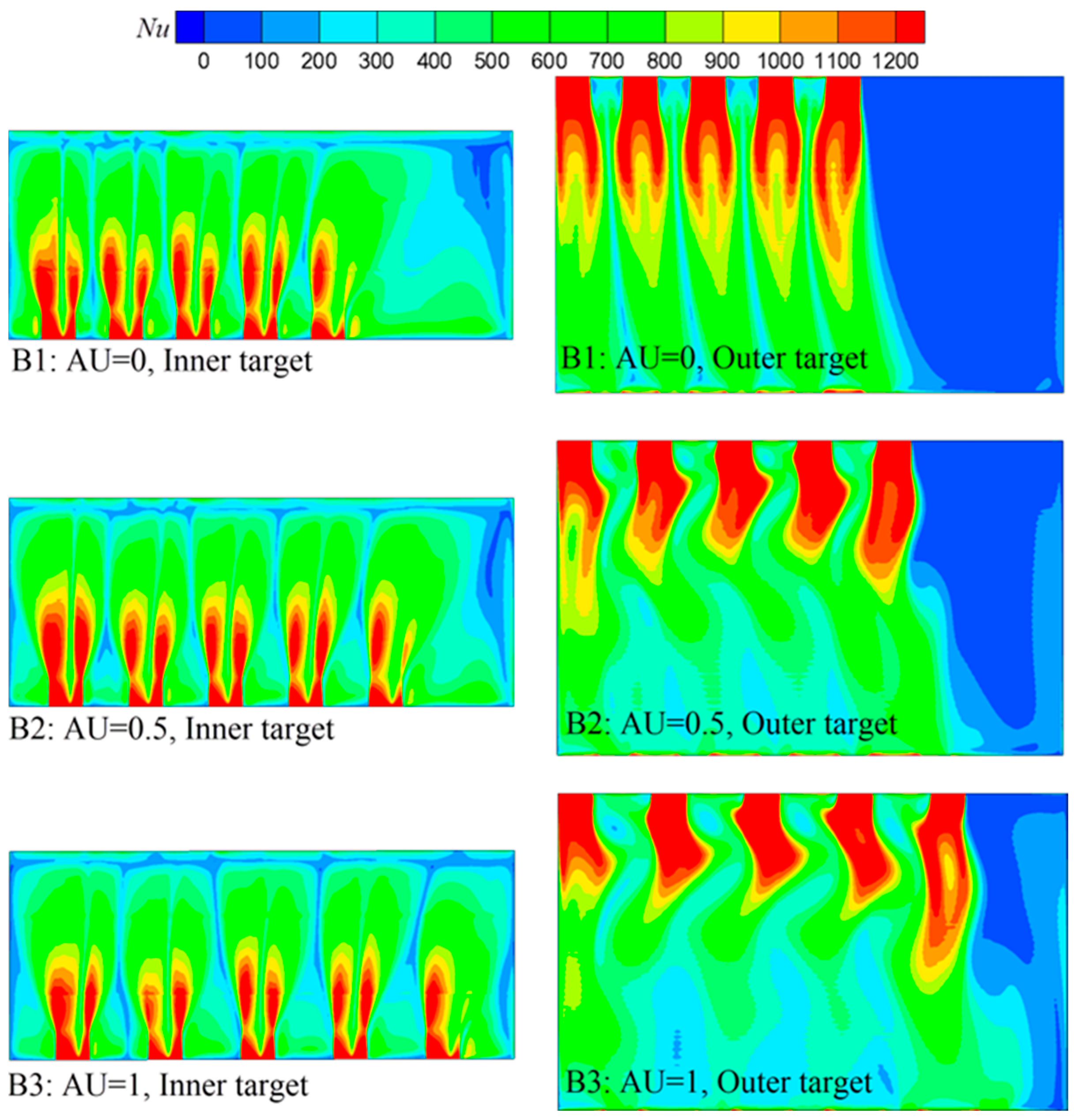
The heat transfer performance is closely related to the flow characteristics. The
Nu contours on both targets are given in
Figure 14. As can be seen, the
Nu distributions on the inner targets for the three cases were similar to each other, and the five high
Nu stripe regions appeared near five nozzles. Although the Nusselt number in the region away from the nozzles for case AU = 0 was smaller than case AU = 1 due to the axial uniformity, the overall
Nu distribution on the inner target had a small difference. However, for the outer target, the low
Nu region away from the nozzles grew smaller as the AU increased. This is because the flow in the narrowed outer chamber was terrible, and the heat transfer was, not surprisingly, influenced. The influence was weakened when the nozzle distribution was arranged more uniformly. Generally, the heat transfer uniformity is enhanced when the nozzle arrangement is more dispersed.
Table 3 gives an assessment of the global flow and heat transfer factors of Group B. As AU increased from 0 to 1, the total pressure loss and friction coefficient slightly increased. This suggests that the flow loss increased with increasing AU, but the difference was not large. For the averaged Nusselt number on the inner surface, the case of AU = 0.5 was 3% larger than the case of AU = 0 and 1. The averaged Nusselt number on the outer surface, as well as the globally averaged Nusselt number, increased as the AU increased, and B3 was 6.6% larger than B1. This suggests that, as the axial uniformity increases, the double-wall vertex cooling configuration has a small increase in flow loss, but a large increase in the heat transfer intensity. Considering the comprehensive estimate of the flow and heat transfer characteristics, the thermal performance factor of case AU = 1 was 5.3% larger than case AU = 0.
4.3. Influences of the Nozzle Number
The number of nozzles is an important factor in the flow and heat transfer behavior, because too many numbers would reduce the global heat transfer intensity and too less numbers would bring about large local thermal stress and global flow loss. In this section, the nozzle numbers (N) of 2, 3, 4, and 5 are discussed.
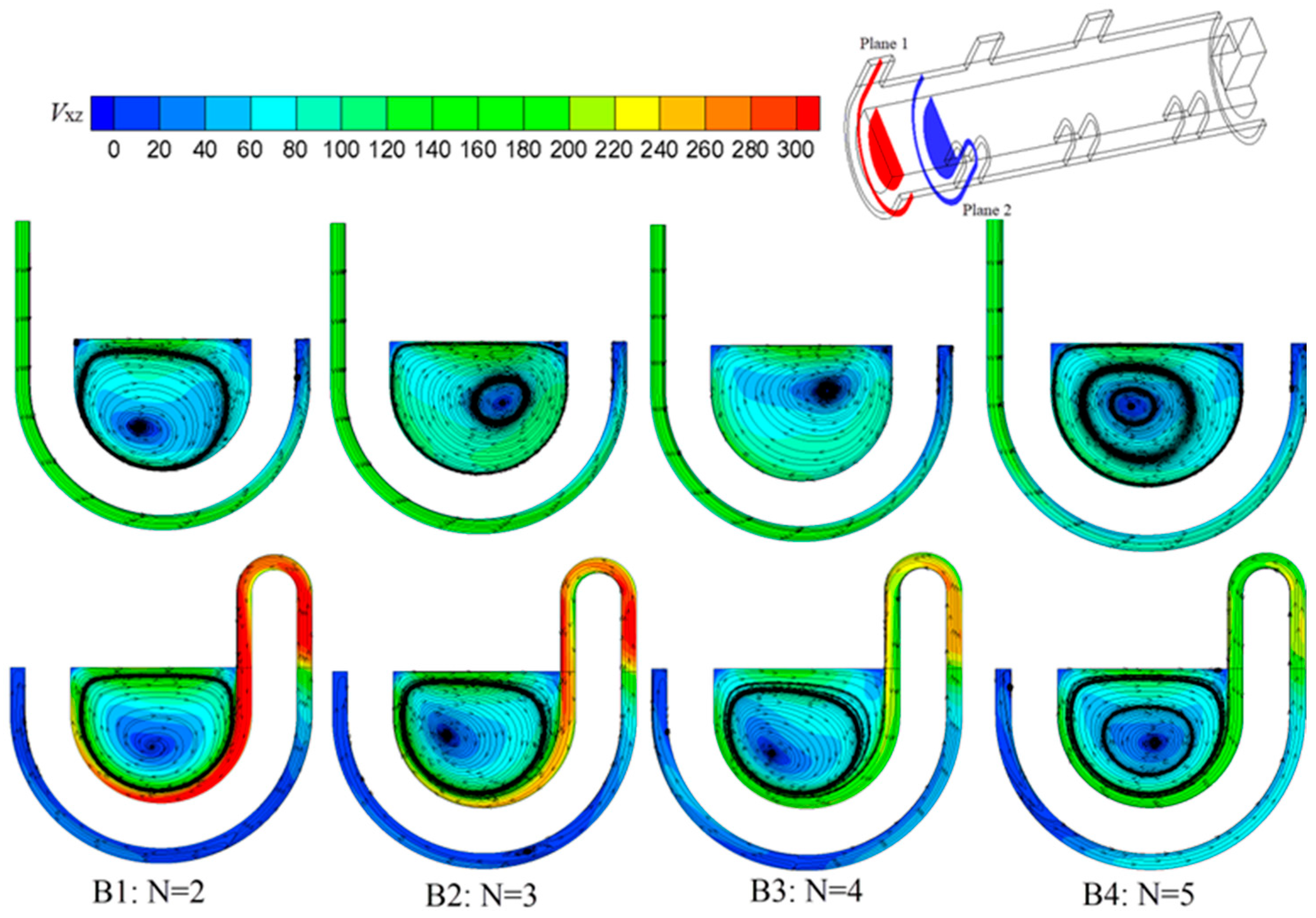
Figure 15 shows the streamlines and velocity distributions on the cross-sections of the adjacent nozzle plane (plane 1) and U-shape plane (plane 2).
It is noted that the position of plane 2 changed with the nozzle number. Since the inlet mass flow rate was the same for all cases, the velocity of the inlet decreased from 147.2 m·s−1 to 130.6 m·s−1 as the nozzle number increased from 2 to 5. However, the velocity decline was not as great as expected, because the coolant density decreased at the same time as the nozzle number increased. As can be seen in the figure, the nozzle number had little influence on the inlet sections, and the velocity change was not obvious in the outer chamber on plane 1. However, the small decrease in inlet velocity caused a significant difference in the velocity distribution in the inner chamber. As N increased from 2 to 5, the velocity out of the U-shape passage decreased obviously, and the velocity in the inner chamber decreased as well. This was because, when the coolant flowed through the outer chamber, the narrowed outer chamber and the gap between the nozzle and U-shape passage caused the flow velocity to redistribute. Therefore, the velocity difference through U-shaped passages was larger than that through inlet nozzles.
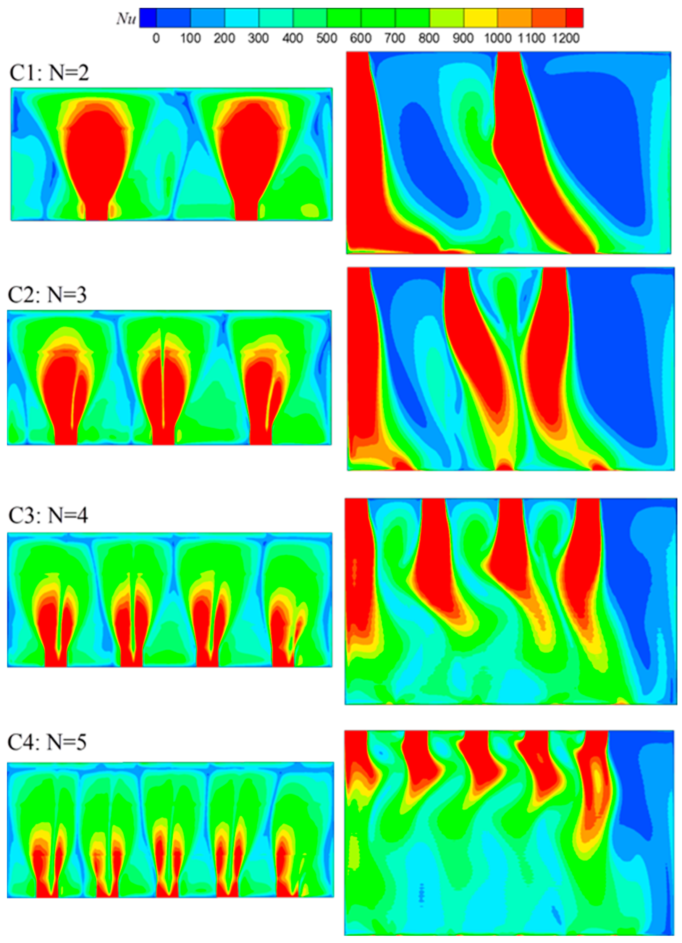
Figure 16 presents the
Nu contours on both targets of Group C. For both targets, the Nusselt number distribution shows vortex cooling characteristics with long, high
Nu stripes. As the nozzle number increased, the local heat transfer intensity decreased, while the global
Nu distribution was more uniform. Similarly,
Table 4 further gives the assessment of global flow and heat transfer factors. The total pressure loss and friction coefficient decreased as N increased. For both
Nua, in and
Nua, out, the case of N = 3 had the largest number. The globally averaged Nusselt number increased first and then decreased, and the case N = 3 reached the peak value. Due to the same inlet boundary condition, the velocity through the inner chamber decreased with the increasing nozzle number. It decreased the local intensity and improved the overall uniformity. The decrease in local heat transfer intensity caused the Nusselt number to reduce, while the uniformity improvement caused the Nusselt number to increase. Under the combined effect of both, the
Nua came up first and then reduced, and N = 3 reached the peak value. Actually, the
Nua of case N = 3 was 69.5% higher than that of case N = 5. Considering the comprehensive effects of flow and heat transfer,
j of case N = 3 was the highest compared to the other cases, and this suggests that nozzle number 3 is the most suitable for the variant configuration.
4.4. Influences of the Aspect Ratio
The aspect ratio of nozzles is another important parameter. In this section, four aspect ratios, AR = 2, 4, 6, and 8, at fixed values of AU = 1 and N = 3 are chosen for discussion. The width of nozzle was kept constant, and the length was changed to set various aspect ratios. Firstly, the circumferentially averaged velocity distribution along the axial direction on the inner and outer surfaces of Group D is given in
Figure 17. As AR and the nozzle length increased, the velocity near nozzles on the outer surface decreased, but the decrease was not as large as that on the inner surface. Generally speaking, the velocity of the flow out of inlet nozzles should decrease as the AR increases because of the decreasing inlet nozzle area. But due to the special outer chamber structure, the vertex along the axial direction appeared in the outer chamber, and it caused a higher degree of mixing. Therefore, the velocity difference for the cases was reduced. For the inner chamber, the influence of the aspect ratio was more obvious. Case AR = 2 had the largest velocity near nozzle regions, and it presented a peak distribution. As the AR increased, the velocity near nozzle regions gradually decreased. Furthermore, for the regions between nozzles, the velocity also decreased as AR increased. The velocity distribution suggests that a smaller aspect ratio, or a smaller nozzle length, is more beneficial to the high local velocity on the inner target, but the influence is weakened on the outer target due to the special structure of the outer chamber.
The
Nu distributions on the inner and outer targets of Group D are given in
Figure 18. Generally, the value of the Nusselt number near the nozzle and U-shape regions and the area occupied by high-Nusselt regions decrease with increasing AR, which is unsurprising due to the velocity distribution. It is noted that the other regions for different cases have similar
Nu distributions on the inner targets, and that a case with a higher AR would have a more uniform Nusselt distribution. For the small-AR cases of AR = 2 and AR = 4, the
Nu distribution on the outer target was more irregular compared to the large-AR cases of AR = 6 and AR = 8. This is because the small nozzle length causes more complex velocity distribution in the outer chamber.
Table 5 gives the flow and heat transfer evaluation parameters of Group D. From the above discussion, although the case AR = 2 had the largest velocity near nozzles and U-shape passages, the total pressure loss and friction coefficient were very large. In addition, the friction coefficient of case AR = 2 was much higher than those of the other three cases. For
Nua, it increased first and then decreased as AR increased. The case of AR = 4 reached the peak value. The
Nua value of case AR = 4 was 14.2%, 67.8%, and 86.0% higher than cases AR = 2, 6, and 8. Compared to the reference case of AR = 2, the thermal performance factor of case AR = 4 was 39% larger, while those of the other two cases were smaller. This is because as AR increased, the increasing nozzle area reduced the coolant velocity but increased the flowing area. The reducing velocity was not conducive to cooling, but the increasing area was beneficial. When the influences of two factors were considered together, it turned out that AR = 4 had the best heat transfer intensity. The results in this section show that the aspect ratio of nozzles has an important influence on the flow and heat transfer performance, and it should be carefully chosen to improve the cooling performance for the double-wall vortex cooling configuration.
5. Conclusions
Efficient cooling methods are significant to modern gas turbine development, and it is worth it to explore new cooling methods. For a series of research on the double-wall vortex cooling method, a variant configuration of double-wall vortex cooling was established. A numerical simulation was conducted to explore this new structure by comparing it with the original configuration. The influences of different axial uniformities, different nozzle numbers, and different nozzle aspect ratios were further discussed.
Compared to the original configuration, the variant configuration had a better streamline distribution with vortex flows in both the inner and outer chamber and a higher heat transfer intensity on the outer target, with a 17.1% increase in the globally averaged Nusselt number. The original configuration has its advantage in inner-surface heat transfer performance, while the variant configuration has its advantage in outer-surface heat transfer performance. Generally speaking, the variant configuration is a good improvement compared to the original one.
The flow in the narrowed outer chamber is not a typical vortex flow due to its special semicircular space. Therefore, the flow inside the outer chamber is complex and would weaken the influences of nozzle geometries. As axial uniformity increased, the velocity and Nusselt number distributions became more uniform. There was a small increase in flow loss, but a large increase in heat transfer with increasing axial uniformity. The case with uniformly distributed nozzles (AU = 1) had the best cooling performance, and the thermal performance factor of case AU = 1 was 5.3% higher than that of case AU = 0.
As the nozzle number increased, the total pressure loss and friction coefficient decreased, but the heat transfer increased first and then decreased. The Nua of case N = 3 was 69.5% higher than that of case N = 5. The case with three nozzles showed the best comprehensive cooling behavior. The aspect ratio has important influences on the double-vortex cooling configuration. Cases with small aspect ratios have higher local heat transfer intensity, but the flow loss is larger. The differences in flow and heat transfer performance for the cases were large. The case with an aspect ratio of 4 had the best cooling performance, and the thermal performance factor of case AR = 4 was 39% larger than case AR = 2.
Double-wall cooling is an efficient cooling method for gas turbine blades, and the new double-wall vortex cooling method has shown its advantages in heat transfer performance. The origin double-wall vortex cooling, emphasizing inner-surface cooling and the more important out-surface cooling, is not good. The work in this paper has overcome this shortcoming. However, the flow resistance of this new double-wall vortex cooling configuration is still high, and it needs more work to improve the flow performance. Furthermore, it is worth noting that the cooling system using channels is suitable for gas turbines with high turbine inlet temperature, like the heave-duty gas turbines. We hope that the work in this paper will contribute to the development of blade-cooling technology.
Author Contributions
Experiment, review and editing, Y.C.; conceptualization and writing, X.L.; validation, Y.S.; conceptualization, formal analysis, and review, X.F.; supervision, J.W. All authors have read and agreed to the published version of the manuscript.
Funding
This work is funded by The National Natural Science Foundation of China Youth Found Project (founder is The National Natural Science Foundation of China, founding number is 12302387), The Innovation and Entrepreneurship Program of Jiangsu Province (founder is Government of Jiangsu Province, founding number is JSSCBS20210981) and The Jiangsu Natural Science Foundation of Youth Found Project (founder is The Jiangsu Natural Science Foundation, founding number is BK20220650).
Data Availability Statement
The data are available from the corresponding author upon reasonable request.
Conflicts of Interest
The authors declare no conflict of interest.
Abbreviations
| a | nozzle length, m |
| b | nozzle width, m |
| c | gap distance between adjacent nozzle and U-shape passage, m |
| c0 | maximum gas distance when nozzles are arranged uniformly to the greatest extent, m |
| D | hydraulic diameter of the vortex chamber |
| h | heat transfer coefficient, W/(m2·K) |
| Nu | Nusselt number, qD/λ (Tw − Ti) |
| Nua | Globally averaged Nusselt number |
| Nuc | Circumferentially averaged Nusselt number |
| q | wall heat flux, W/m2 |
| Ti | inlet temperature, K |
| Tw | target wall temperature, K |
| Vxz | circumferentially averaged velocity on XZ section, (V2x + V2z)1/2, m·s−1 |
| Z | axial direction, m |
| Greek Symbols | |
| λ | fluid thermal conductivity, W/(m·K) |
References
- Han, J.C.; Dutta, S.; Ekkad, S.V. Gas Turbine Heat Transfer and Cooling Technology; Taylor & Francis: New York, NY, USA, 2000; pp. 1–5. [Google Scholar]
- Han, J.C.; Sandip, D. Recent developments in turbine blade internal cooling. Ann. N. Y. Acad. Sci. 2001, 934, 162–178. [Google Scholar] [CrossRef] [PubMed]
- Hedlund, C.R.; Ligrani, P.M.; Moon, H.K.; Glezer, B. Heat transfer and flow phenomena in a swirl chamber simulating turbine blade internal cooling. J. Turbomach. 1999, 121, 804–813. [Google Scholar] [CrossRef]
- Hedlund, C.R.; Ligrani, P.M. Local swirl chamber heat transfer and flow structure at different Reynolds numbers. J. Turbomach. 2000, 122, 375–385. [Google Scholar] [CrossRef]
- Hedlund, C.R.; Ligrani, P.M.; Glezer, B.; Moon, H.K. Heat transfer in a swirl chamber at different temperature ratios and Reynolds numbers. Int. J. Heat Mass Transf. 1999, 42, 4081–4091. [Google Scholar] [CrossRef]
- Biegger, C.; Rao, Y.; Weigand, B. Flow and heat transfer measurements in swirl tubes with one and multiple tangential inlet jets for internal gas turbine blade cooling. Int. J. Heat Fluid Flow 2016, 73, 174–187. [Google Scholar] [CrossRef]
- Rao, Y.; Biegger, C.; Weigand, B. Heat transfer and pressure loss in swirl tubes with one and multiple tangential jets pertinent to gas turbine internal cooling. Int. J. Heat Mass Transf. 2017, 106, 1356–1367. [Google Scholar] [CrossRef]
- Seibold, F.; Ligrani, P.; Weigand, B. Flow and heat transfer in swirl tubes—A review. Int. J. Heat Mass Transf. 2022, 187, 122455. [Google Scholar] [CrossRef]
- Bunker, R.S. Gas Turbine Cooling: Moving from Macro to Micro Cooling. In Proceedings of the Asme Turbo Expo: Turbine Technical Conference & Exposition, San Antonio, TX, USA, 3–7 June 2013. [Google Scholar]
- Gillespie, D.R.H.; Wang, Z.; Ireland, P.T.; Kohler, S.T. Full Surface Local Heat Transfer Coefficient Measurements in a Model of an Integrally Cast Impingement Cooling Geometry. J. Turbomach. 1998, 120, 92–99. [Google Scholar] [CrossRef]
- Li, W.; Lu, X.; Li, X.; Ren, J.; Jiang, H. On Improving Full-Coverage Effusion Cooling Efficiency by Varying Cooling Arrangements and Wall Thickness in Double Wall Cooling Application. J. Heat Transf. 2019, 141, 042201. [Google Scholar] [CrossRef]
- Liu, X.; Zhang, C.; Song, L.; Li, J. Influence of Biot number and geometric parameters on the overall cooling effectiveness of double wall structure with pins. Appl. Therm. Eng. 2021, 198, 117439. [Google Scholar] [CrossRef]
- Liu, Y.; Rao, Y.; Yang, L.; Xu, Y.; Terzis, A. Flow and heat transfer characteristics of double-wall cooling with multi-row short film cooling hole arrangements. Int. J. Therm. Sci. 2021, 165, 106878. [Google Scholar] [CrossRef]
- Murray, A.V.; Ireland, P.T.; Romero, E. Development of a Steady-State Experimental Facility for the Analysis of Double-Wall Effusion Cooling Geometries. J. Turbomach. 2019, 141, 041008. [Google Scholar] [CrossRef]
- Li, G.; Yang, P.; Zhang, W.; Mo, W. Degradation of the cooling performance of the double wall nozzle guide vane in an engine. Appl. Therm. Eng. 2020, 167, 114765. [Google Scholar] [CrossRef]
- Wright, E.; Ahmed, A.; Yan, Y.; Maltson, J.; Lopez, L.A. Experimental and Numerical Heat Transfer Investigation of Impingement Jet Nozzle Position in Concave Double-Wall Cooling Structures. Heat Transf. Eng. 2021, 43, 1108–1118. [Google Scholar] [CrossRef]
- Yang, L.; Li, W.; Ren, J.; Chyu, M.; Jiang, H. Influence of Topology on Heat Transfer in a Double Wall Cooling Channel: Potential of Series-Linked Jets. In Proceedings of the Asme Turbo Expo: Turbomachinery Technical Conference & Exposition, Seoul, Republic of Korea, 13–17 June 2016. [Google Scholar]
- Rogers, N.; Ren, Z.; Buzzard, W.; Sweeney, B.; Tinker, N.; Ligrani, P.; Hollingsworth, K.; Liberatore, F.; Patel, R.; Moon, H.K. Effects of Double Wall Cooling Configuration and Conditions on Performance of Full Coverage Effusion Cooling. In Proceedings of the Asme Turbo Expo: Turbomachinery Technical Conference & Exposition, Seoul, Republic of Korea, 13–17 June 2016. [Google Scholar]
- Zhang, X.D.; Liu, J.; An, B.T. The Influences of Film Hole Size and Coolant Ejection Angle on Overall Cooling Effectiveness of Laminated Cooling. In Proceedings of the Asme Turbo Expo: Turbine Technical Conference & Exposition, Düsseldorf, Germany, 16–20 June 2014; American Society of Mechanical Engineers: New York, NY, USA, 2014. [Google Scholar]
- Rao, Y. Jet Impingement Heat Transfer in Narrow Channels with Different Pin Fin Configurations on Target Surfaces. J. Heat Transf. Trans. ASME 2018, 140, 072201. [Google Scholar] [CrossRef]
- Liu, Y.; Rao, Y.; Yang, L. Numerical simulations of a double-wall cooling with internal jet impingement and external hexagonal arrangement of film cooling holes. Int. J. Therm. Sci. 2020, 153, 106337. [Google Scholar] [CrossRef]
- Rao, Y.; Liu, Y.; Wan, C. Multiple-jet impingement heat transfer in double-wall cooling structures with pin fins and effusion holes. Int. J. Therm. Sci. 2018, 133, 106–119. [Google Scholar] [CrossRef]
- Vanga, S.R.; Ligrani, P.M.; Knox, J.; Liberatore, F.; Patel, R.; Ho, Y.-H. Louver and effusion cooling heat transfer for a double wall effusion plate with impingement jet array coolant supply. Int. J. Heat Mass Transf. 2021, 168, 120861. [Google Scholar] [CrossRef]
- Fan, X. Numerical research of a new vortex double wall cooling configuration for gas turbine blade leading edge. Int. J. Heat Mass Transf. 2022, 183, 122048. [Google Scholar] [CrossRef]
- Li, Z.; Wang CLi, L.; Wu, J.; Yin, Z.; Tan, D. Numerical investigation of mesoscale multiphase mass transport mechanism in fibrous porous media. Eng. Appl. Comput. Fluid Mech. 2024, 18, 2363246. [Google Scholar] [CrossRef]
- Li, L.; Xu, P.; Xu, W.; Lu, B.; Wang, C.; Tan, D. Multi-field coupling vibration patterns of the multiphase sink vortex and distortion recognition method. Mech. Syst. Signal Process. 2024, 219, 111624. [Google Scholar] [CrossRef]
- Fan, X.; He, C.; Gan, L.; Li, L.; Du, C. Experimental study of swirling flow characteristics in a semi cylinder vortex cooling configuration. Exp. Therm. Fluid Sci. 2020, 113, 110036. [Google Scholar] [CrossRef]
- Fan, X.; Li, L.; Zou, J.; Wang, J.; Wu, F. Local heat transfer of vortex cooling with multiple tangential nozzles in a gas turbine blade leading edge cooling passage. Int. J. Heat Mass Transf. 2018, 126, 377–389. [Google Scholar] [CrossRef]
Figure 1.
The schematic figure of a plate-based double-wall structure.
Figure 1.
The schematic figure of a plate-based double-wall structure.
Figure 2.
The double-wall vortex cooling structures implanted in blades. (
a) The double-wall vortex cooling configuration in the present study. (
b) The double-wall vortex cooling configuration in the previous study [
24].
Figure 2.
The double-wall vortex cooling structures implanted in blades. (
a) The double-wall vortex cooling configuration in the present study. (
b) The double-wall vortex cooling configuration in the previous study [
24].
Figure 3.
The geometrical structures of research group A. The length and width of nozzles are 4 mm and 1 mm.
Figure 3.
The geometrical structures of research group A. The length and width of nozzles are 4 mm and 1 mm.
Figure 4.
The main geometric details of research groups B, C, and D.
Figure 4.
The main geometric details of research groups B, C, and D.
Figure 5.
The mesh generation and geometrical dimensions.
Figure 5.
The mesh generation and geometrical dimensions.
Figure 6.
Grid independence calculation.
Figure 6.
Grid independence calculation.
Figure 7.
Schematic diagram of experimental system.
Figure 7.
Schematic diagram of experimental system.
Figure 8.
The configuration used for validation.
Figure 8.
The configuration used for validation.
Figure 9.
Results of vortex flow validation.
Figure 9.
Results of vortex flow validation.
Figure 10.
Results of heat transfer validation.
Figure 10.
Results of heat transfer validation.
Figure 11.
Streamlines of group A.
Figure 11.
Streamlines of group A.
Figure 12.
Nu contours on both targets of Group A.
Figure 12.
Nu contours on both targets of Group A.
Figure 13.
The circumferentially averaged velocity distribution along the axial direction on the inner and outer surfaces of Group B.
Figure 13.
The circumferentially averaged velocity distribution along the axial direction on the inner and outer surfaces of Group B.
Figure 14.
Nu contours on both targets of Group B.
Figure 14.
Nu contours on both targets of Group B.
Figure 15.
Streamlines and velocity distributions on nozzle and U-shaped passage sections of Group B.
Figure 15.
Streamlines and velocity distributions on nozzle and U-shaped passage sections of Group B.
Figure 16.
Nu contours on both targets of Group C.
Figure 16.
Nu contours on both targets of Group C.
Figure 17.
The circumferentially averaged velocity distribution axially on both surfaces of Group D.
Figure 17.
The circumferentially averaged velocity distribution axially on both surfaces of Group D.
Figure 18.
Nu contours on both targets of Group D.
Figure 18.
Nu contours on both targets of Group D.
Table 1.
All researched cases.
Table 1.
All researched cases.
| Groups | A: Comparison | B: Axial Uniformity | C: Nozzle Numbers | D: Aspect Ratio |
|---|
| A1 | A2 | B1 | B2 | B3 | C1 | C2 | C3 | C4 | D1 | D2 | D3 | D4 |
|---|
| Configuration type | Variation | Origin | Variation | Variation | Variation |
| AU | 1 | 0 | 0.5 | 1 | 1 | 1 |
| N | 5 | 5 | 2 | 3 | 4 | 5 | 3 |
| AR | 4 | 4 | 4 | 2 | 4 | 6 | 8 |
Table 2.
Quantitative parameter comparison of Group A.
Table 2.
Quantitative parameter comparison of Group A.
| Parameters | Group A |
|---|
| A1: Variation | A2: Origin |
|---|
| η | 44.8% | 40.2% |
| f | 2.253 | 0.414 |
| Nua, in | 525.7 | 721.0 |
| Nua, out | 483.2 | 234.4 |
| Nua | 500.2 | 427.0 |
Table 3.
Flow and heat transfer evaluation parameters of Group B.
Table 3.
Flow and heat transfer evaluation parameters of Group B.
| Parameters | Group B |
|---|
| B1: AU = 0 | B2: AU = 0.5 | B3: AU = 1 |
|---|
| η | 44.4% | 44.7% | 44.8% |
| f | 2.172 | 2.183 | 2.253 |
| Nua, in | 526.9 | 542.8 | 525.7 |
| Nua, out | 431.2 | 451.5 | 483.2 |
| Nua | 469.4 | 487.9 | 500.2 |
| j/j0 | 1 | 1.038 | 1.053 |
Table 4.
Flow and heat transfer evaluation parameters of Group C.
Table 4.
Flow and heat transfer evaluation parameters of Group C.
| Parameters | Group C |
|---|
| C1: N = 2 | C2: N = 3 | C3: N = 4 | C4: N = 5 |
|---|
| η | 75.6% | 63.0% | 52.7% | 44.8% |
| f | 4.295 | 2.563 | 2.463 | 2.253 |
| Nua, in | 713.9 | 840.4 | 572.0 | 525.7 |
| Nua, out | 547.8 | 879.0 | 559.0 | 483.2 |
| Nua | 594.8 | 847.7 | 566.6 | 500.2 |
| j/j0 | 1 | 1.69 | 1.15 | 1.04 |
Table 5.
Flow and heat transfer evaluation parameters of Group D.
Table 5.
Flow and heat transfer evaluation parameters of Group D.
| Parameters | Group D |
|---|
| D1: AR = 2 | D2: AR = 4 | D3: AR = 6 | D4: AR = 8 |
|---|
| η | 81.4% | 63.0% | 48.7% | 37.9% |
| f | 4.629 | 2.563 | 2.233 | 2.260 |
| Nua, in | 760.1 | 840.4 | 553.2 | 468.8 |
| Nua, out | 730.1 | 879.0 | 455.7 | 442.7 |
| Nua | 742.1 | 847.7 | 505.2 | 455.7 |
| j/j0 | 1 | 1.39 | 0.87 | 0.78 |
| Disclaimer/Publisher’s Note: The statements, opinions and data contained in all publications are solely those of the individual author(s) and contributor(s) and not of MDPI and/or the editor(s). MDPI and/or the editor(s) disclaim responsibility for any injury to people or property resulting from any ideas, methods, instructions or products referred to in the content. |
© 2024 by the authors. Licensee MDPI, Basel, Switzerland. This article is an open access article distributed under the terms and conditions of the Creative Commons Attribution (CC BY) license (https://creativecommons.org/licenses/by/4.0/).
