Abstract
The following study investigates the effectiveness of a deep learning-based method for predicting the flow field and flow-driven rotation of a vertical-axis hydrokinetic turbine operating in previously unseen free-stream velocities. A Convolutional Neural Network (CNN) is trained and tested using the solutions of five two-dimensional (2-D), foil-resolved Unsteady Reynolds-Averaged Navier-Stokes (URANS) simulations, with free-stream velocities of 1.0, 1.5, 2.0, 2.5, and 3.0 m/s. Based on the boundary conditions of free-stream velocity and rotor position, the flow fields of x-velocity, y-velocity, pressure, and turbulent viscosity are inferred, in addition to the angular velocity of the rotor. Three trained CNN models are developed to evaluate the effects of (1) the dimensions of the training data, and (2) the number of simulations used as training cases. Reducing data dimensions was found to diminish mean relative error in predictions of velocity and turbulent viscosity, while increasing it in predictions of pressure and angular velocity. Increasing the number of training cases from two to three was found to reduce relative error for all predicted unknowns. With the best achieved CNN model, the variables of x-velocity, y-velocity, pressure, turbulent viscosity, and angular velocity were inferred with mean relative errors of 6.93%, 9.82%, 10.7%, 7.48%, and 0.817%, respectively.
1. Introduction
The optimization of turbine array layouts is an important and challenging problem in the fields of wind and hydrokinetic energy. The maximization of aerodynamic array efficiency, which is defined as the energy output of the entire array in proportion to the energy output of an equal number of isolated turbines [1], requires vastly different array layouts for horizontal-axis and vertical-axis turbines. In order to achieve an array efficiency of about 90%, horizontal-axis wind turbines (HAWTs) are generally spaced by eight to ten rotor diameters in the streamwise direction, and three to five rotor diameters in the cross-flow direction [1]. In contrast, the energy output of vertical-axis turbine arrays is enhanced by aerodynamic interactions, especially when turbines are arranged in counter-rotating pairs [2]. The synergy of closely spaced vertical-axis wind turbines (VAWTs) has been demonstrated in field [2] and wind tunnel experiments [3,4], as well as by numerical models [5,6,7,8,9]. In wind tunnel tests, counter-rotating VAWT pairs with a spacing of 1.25 turbine diameters were shown to improve array efficiency by an average of 14% over a wind direction range of 50° [4]. In field analyses of VAWT triads, the efficiency of an isolated turbine was found to be 95% recovered at four turbine diameters downstream from a counter-rotating pair [2]. With optimal layouts, it is expected that VAWT arrays could achieve power densities an order of magnitude greater than those seen in HAWT arrays, which are typically in the range of 2 to 3 W/m2 [2]. Although the phenomenon of vertical-axis turbine synergy is well documented, further investigation is required to optimize the layouts of vertical-axis turbine arrays with greater precision.
Due to the high computational cost of foil-resolved turbine simulations, turbine arrays are generally modelled by replacing complex rotor geometries with zero-thickness, permeable momentum sinks, commonly referred to as actuators. To eschew the resolution of boundary layers, the flow at the actuator is assumed to be inviscid. In general, actuators can be classified as non-rotating or rotating, i.e., exerting a static or dynamic load on the fluid domain, respectively. Non-rotating actuators take the form of the swept area of the foils, i.e., a cylinder for straight-bladed vertical-axis turbines, and a disc for horizontal-axis turbines. Rotating actuators, on the other hand, are comprised of lines or surfaces that track with the position of each foil, coinciding with the aerodynamic center or chord line, respectively.
Actuator Cylinders (ACs) are produced by discretizing the swept area of the foils and computing the normal and tangential blade forces produced at each element, based on the local relative flow velocity and angle of attack [10]. The calculated forces are then used to determine the flow velocities induced downstream of each element [10]. Two-dimensional AC models can be performed for straight-bladed turbines, while three-dimensional AC models can be developed for turbines with curved blades [11]. To account for the effects of the rotor shaft and struts, actuator-in-actuator models consisting of two concentric cylinders have also been developed [12]. AC models have been shown to accurately predict power coefficients of isolated turbines when validated against experimental and numerical results [10,13], although discrepancies have been observed for high-solidity turbines [13]. In studies deploying AC models with inviscid flow solvers, interactions between VAWT pairs have been shown to increase array efficiency by more than 10% [11]. Experimentally and numerically validated AC models have also been coupled with RANS solvers to predict power outputs and blockage effects in marine turbine arrays [14,15].
While more computationally expensive than AC models, Actuator Line (AL) models are able to approximate important transient effects such as foil tip vortices and swirl, both of which have a significant impact on wake evolution and power production. In AL models, the static lift, drag, and pitching moment coefficients of the actuator elements are interpolated from coefficient lookup tables at each time step, based on the local relative fluid velocity and angle of attack [16]. Using the computed coefficients, the forces incident on each actuator element are determined, and projected back onto the fluid domain as a momentum source term [16]. AL models rely on empirical corrections and carefully calibrated foil data to prescribe the projection of calculated body forces from the actuator elements onto the fluid domain, and the injection of leading and trailing edge vortices [16]. To account for the unsteady effects of dynamic stall and added mass, static foil characteristics must be corrected at each time step, based on the local flow field of the actuator element [16]. The prediction of dynamic stall, in particular, has been identified as a weakness in AL models [17]. For vertical-axis turbines, lift and drag coefficients must also be corrected to account for the phenomenon of flow curvature, wherein the circular path of the foils results in a non-uniform angle of attack along the chord line [16]. With properly calculated aerodynamics loads, AL models have been shown to resolve flow fields almost as accurately as foil-resolved models [17]. In addition, high-fidelity AL models coupled with RANS or Large Eddy Simulation (LES) solvers have been highly effective in the analysis of interactions between VAWT pairs and triads [5,6].
Unlike AC and AL models, foil-resolved models are rarely used as a method for optimizing turbine arrays, due to their large computational cost. Nevertheless, such rigorous optimizations are attainable. In a recent study, 2-D foil-resolved URANS simulations were carried out for 24 layouts of a VAWT pair, and for a single configuration of a VAWT triad [7]. Each simulation was performed with the same inlet velocity, and with the same constant angular velocity applied to each rotor [7]. For the assessed pair layouts, array efficiency was enhanced by as much as 15% [7]. With the addition of a third turbine, array efficiency was increased by another 3% [7]. While turbine arrays are typically modelled by assuming that each turbine has the same fixed angular velocity, models employing flow-driven rotation can more accurately replicate the turbine interactions observed in field and laboratory experiments. In such models, the angular velocity of each turbine in the array is calculated at every time step, based on its local velocity field. This method was recently implemented in 2-D foil-resolved URANS models to examine the performance of co-rotating and counter-rotating VAWT pairs in 16 wind directions [9]. For VAWT pairs with spacings of 0.5 to 1 turbine diameters, array efficiency was found to improve by as much as 23% [9]. In addition, the closely spaced turbines were shown to exhibit phase synchronization, a phenomenon that had not previously been demonstrated in numerical models [9]. Although performing foil-resolved URANS simulations for numerous array layouts is exceedingly time consuming, such stringent studies are critical for the validation of actuator-based array models. Moreover, foil-resolved models will undoubtedly play an important role in the improvement of vertical-axis turbine designs for pairwise or cluster-wise operation.
To reduce the computational cost of foil-resolved array modelling, predictive deep learning techniques should be investigated. Deep learning refers to a category of machine learning that employs Artificial Neural Networks (ANNs), which are computational models that transform inputs through three or more interconnected layers of nodes, or neurons. ANNs are trained to extract non-linear relationships between inputs and ground truths through an iterative process, in which trainable parameters in each node are adjusted to reduce the discrepancy between the output of the ANN and the target solution. Given their capacity to extract general patterns from highly complicated data, ANNs are a powerful method for reducing the computational cost associated with the modelling of physical field phenomena. By training an ANN with the solutions of foil-resolved array models, the performance of previously unseen turbine layouts could potentially be predicted, thereby reducing the number of foil-resolved simulations that must be performed to find an optimal array configuration.
Convolutional Neural Networks (CNNs), which are a class of ANNs, are particularly well-suited to applications involving array-based data. While CNNs are often used for image classification and segmentation, they can also be trained to infer the solutions of Computational Fluid Dynamics (CFD) models. CNNs have been applied to a broad range of CFD problems, including the modelling of flow fields around bluff bodies and foils [18,19,20,21], the modelling of convective heat transfer in U-bend channels [22], and the optimization of airfoil and heat sink geometries [23]. When trained with the solutions of 2-D RANS simulations, CNNs have been shown to predict velocity and pressure fields around previously unseen airfoil shapes with a relative error of less than 3% [20]. Despite their demonstrated efficacy in thermofluid applications, CNNs are not governed by physics equations, and their predictions may therefore violate the laws of conservation. For applications requiring especially stringent solutions, computational cost can be reduced by using CNN predictions as boundary conditions in physics-based models. For RANS or LES-based turbulent viscosity models, this approach necessitates the prediction of velocity, pressure, and turbulent viscosity fields. In a study modelling turbulent and steady laminar flows around foils and ellipses, the coupling of a CNN and a 2-D RANS solver was found to reduce computation time by 1.9 to 7.4 times, while satisfying the convergence conditions of the solver [21].
In the field of wind energy, applications of deep learning are expanding. A variety of ANNs have been trained with LES solutions to predict the 2-D velocity fields of HAWT arrays, including a Deep Convolutional Conditional Generative Adversarial Network (DC-CGAN) [24], a Super-Fidelity Network (SFNet) [25], and a Bilateral Convolutional Neural Network (BiCNN) [26]. Even with limited training examples, the predictions of these networks were found to be in good agreement with numerical data. In a similar work, an ANN was trained with the solutions of actuator-RANS simulations to predict the three-dimensional velocity and turbulent kinetic energy fields of a single HAWT, and of multiple HAWTs in series, based on the inflow conditions of velocity and turbulence intensity [27]. For an isolated turbine, velocity and turbulent kinetic energy were predicted with relative errors below 5% [27]. While the capacity of ANNs to predict flow fields around turbines is well established, the concomitant prediction of flow fields and turbine performance would serve as a more comprehensive tool in the optimization of array layouts. Given that rotational power is proportional to angular velocity and torque, the performance of a turbine could potentially be predicted in terms of either variable, while the other variable is prescribed.
With the aim of facilitating the optimization of turbine arrays via foil-resolved models, this study investigates the viability of using a CNN to predict the flow field and flow-driven rotation of a vertical-axis turbine. In the proposed method, a CNN is trained to infer the solutions of a 2-D foil-resolved URANS model for a vertical-axis hydrokinetic turbine operating in free-stream velocities between 1.0 and 3.0 m/s. For the boundary conditions of free-stream velocity and rotor position, the angular velocity of the turbine is predicted, as well as the flow field variables of x-velocity, y-velocity, pressure, and turbulent viscosity. Training and testing data are produced from the solutions of five URANS simulations, with free-stream velocities of 1.0, 1.5, 2.0, 2.5, and 3.0 m/s. Three CNN models are generated and compared to assess the effects of (1) the dimensions of the training data, and (2) the number of simulations that are used as training cases.
The methodology and insights developed through this research are put forward here as a potential steppingstone to a deep learning-based method for optimizing the layouts of vertical-axis turbine pairs and triads. However, the findings of this work may also be relevant in other CFD problems where transient simulations are required for numerous permutations. The main takeaways of this study are as follows:
- Smaller data dimensions were found to produce a lower mean relative error in the velocity and turbulent viscosity fields, and a larger mean relative error in the pressure field. Further investigation is required to improve the concurrent prediction of these flow variables.
- Using three simulations as training cases rather than two was found to yield significantly better results overall. However, a more granular investigation is required to assess how prediction error varies over the considered range of free-stream velocities, using different numbers and combinations of simulations as training cases.
- Although the results obtained in this work are not considered rigorous enough for application in industry, they underscore the potential of deep learning techniques in the modelling of vertical-axis turbines.
2. Materials and Methods
The following section outlines the methodologies underlying the preparation of the numerical turbine model, the generation and processing of data, and the development of the CNN models. The key features and working principles of the developed CNNs are also described.
2.1. URANS Model
To generate training and testing data for the CNNs, 2-D URANS simulations of a vertical-axis turbine are performed in ANSYS Fluent, for the free-stream velocities of 1.0, 1.5, 2.0, 2.5, and 3.0 m/s. Flow-driven turbine rotation is achieved by deploying the dynamic mesh method with the Six Degree of Freedom (6DOF) solver. The decision to apply the dynamic mesh method, as opposed to the sliding mesh approach, was based on the idea that the methodology of this study would be modified to predict the performance of turbine pairs operating with flow-driven rotation. Although the sliding mesh method requires that a rotational velocity be specified, it could just as easily have been applied in this study, with a lower computational cost. In that case, the prediction of the rotor’s angular velocity would have been redundant, and the torque on the rotor (or the resultant power output) could have been predicted instead.
A User-Defined Function (UDF) is used to specify the mass, moment of inertia, and rotational axis of the turbine. The turbine is modelled as free-wheeling, i.e., with no counter-torque applied to the rotor shaft, to achieve higher rotational velocities and steeper gradients in the flow domain. The geometry, mass, and moment of inertia of the turbine modelled in this study are based on those of a 5-kW, four-bladed, H-rotor hydrokinetic turbine, with a 60-inch rotor diameter, and NACA 0018 foils with a chord length of 4 inches and a pitching angle of 4°.
The two-dimensional RANS equation is solved at each time step, assuming an incompressible Newtonian fluid, and zero external body forces on the flow domain. By applying the Boussinesq approximation, the Reynolds stress is made proportional to the strain rate of the mean velocity, with a proportionality coefficient of turbulent viscosity, denoted as µt. The resultant RANS equation can be expressed as follows:
where and are the density and dynamic viscosity of the fluid, respectively, is the mean velocity, and is the mean static pressure. The turbulent viscosity term is solved using the Transition SST turbulence model [28], owing to its proven accuracy in the modelling of vertical-axis turbines [29]. The turbulence intensity of the flow domain is assumed to be 5%, and the turbulent length scale is specified as the diameter of the rotor. To ensure that the network is trained and tested based on stable simulation solutions, data are exported at each time step of the 21st turbine revolution [30]. All simulations are performed using second-order spatial and temporal discretization, with a residual criterion of 1 × 10⁻⁶. To complete this study within a practical time frame, simulations are executed on the Grex high performance computer at the University of Manitoba.
As depicted in Figure 1, the flow domain is divided into three regions: a rectangular outer domain, a square middle domain, and a circular rotor domain. The region over which solutions are inferred by the CNN encompasses the middle and rotor domains.
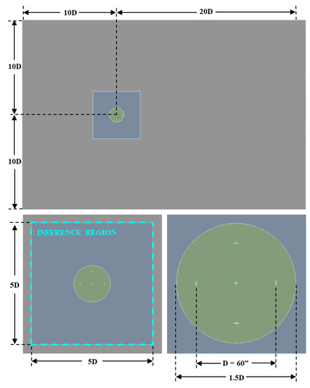
Figure 1.
Flow domain geometry with a demarcated inference region.
The division of the flow domain into discrete zones serves three important purposes. Firstly, the separate zones allow for greater control over the mesh resolution around the turbine. By adjusting the resolution of each zone independently, grid independence can be achieved with fewer grid elements. Secondly, the zones are also used to limit solution exports to the desired CNN inference region, thereby minimizing the memory required to store solution data, and reducing the computational expense of processing solution exports into training and testing data. As can be seen in Figure 1, the border of the inference region coincides with the outer boundary of the middle flow domain. Lastly, the division of the flow domain into discrete zones is required in the deployment of the 6DOF solver, which governs the flow-driven rotation of the rotor. In the configuration of the dynamic mesh, the dynamic rotor domain is defined as rigid, i.e., having an invariant mesh structure. To maintain mesh continuity between the dynamic rotor domain and the rest of the flow field, the middle domain is defined as deforming, i.e., with a mesh structure that is reconstructed at each time step, in accordance with the motion of the rigid rotor domain. The outer domain is defined as stationary, i.e., with a fixed mesh.
Triangular meshing is applied throughout the flow domain, as required by the dynamic mesh method, with a growth rate of 1.1. Twenty layers of inflation meshing are applied around the foils and the rotor shaft, with a growth rate of 1.2. A first-cell height of 2.0 × 10⁻³ mm (y+ ~ 1.7) is applied along all surfaces. The first cell is deliberately placed within the viscous sublayer (y+ < 5), as required by the Transition SST turbulence model [28]. A first-cell width of 0.10 mm (x+ ~ 84) is applied along surfaces in the tangential direction. To estimate the non-dimensional first-cell height and width, the maximum relative velocity of the fluid at the surface of the foils is assumed to be the sum of the maximum free-stream velocity (3.0 m/s) and the magnitude of the tangential velocity of the foil, assuming a maximum rotational velocity of 200 RPM. The inflation layer meshing is depicted in Figure 2.

Figure 2.
Inflation layer meshing around a foil.
A grid independence study is performed by varying the cell size in the outer, middle, and rotor domains. The properties of the meshes evaluated in the grid independence study are summarized in Table 1. Each mesh is evaluated with an inlet velocity of 3.0 m/s and a time step of 1.0 × 10⁻⁴ s.

Table 1.
Properties of the meshes evaluated in the grid independence study.
To ensure that grid independence is achieved without forfeiting computational efficiency, the four meshes are compared in terms of both their solutions and computational expense after 5000 time steps, at time t = 0.50 s. The compared metrics include the rotor angle, the rotor drag and lift coefficients, and the simulation running time. The solutions of Mesh 2 and Mesh 3 were found to deviate from those of the finest mesh (Mesh 1) by an absolute maximum of 3.0%, while reducing computation time by 38% and 46%, respectively. Relative to Mesh 1, Mesh 4 was found to produce absolute discrepancies exceeding 10%, and was therefore deemed inadequate.
Since grid and time step independence are interrelated, further investigation is required to ascertain whether grid independence is maintained with time step sizes larger than the one deployed throughout the first grid independence test (T = 1.0 × 10⁻⁴ s). Although Mesh 2 and Mesh 3 were both found to be viable in the grid independence study, their sensitivity to time step size could differ. Using time steps of 2.0 × 10⁻⁴ s, 4.0 × 10⁻⁴ s, and 5.0 × 10⁻⁴ s, the rotor angles produced by the two meshes at t = 0.50 s are determined. For both meshes, the rotor angles achieved with time steps of 1.0 × 10⁻⁴ s and 2.0 × 10⁻⁴ s were found to be in good agreement, with an absolute difference of less than 2%. Time steps of 4.0 × 10⁻⁴ s and 5.0 × 10⁻⁴ s were found to produce excessive discrepancy in the rotor angle when deployed with Mesh 2, and were therefore not tested with Mesh 3. Based on the results obtained in the grid and time step independence studies, simulations are conducted using Mesh 3, with a time step of 2.0 × 10⁻⁴ s. Mesh 3 is depicted in Figure 3.
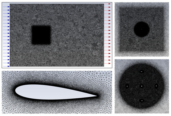
Figure 3.
Flow domain meshing, with blue and red arrows indicating the inlet and outlet of the flow domain, respectively.
The individual and combined computation times of the five performed simulations are shown in Table 2.

Table 2.
Computational cost of each simulation.
2.2. Data Generation
To generate training and testing data for the CNN, flow field data are exported in ASCII format at each time step of the 21st turbine revolution. These exports contain the x-velocity, y-velocity, relative total pressure, turbulent viscosity, and wall shear stress at each node within the specified export region, as well as the coordinates of each node. To minimize the quantity of data that must be stored and processed, flow field exports are limited to the region over which the CNN will be trained to infer solutions, i.e., the middle and rotor domains, as depicted in Figure 1. In addition to the flow field data, a record of the angular position of the rotor domain at each time step is also exported.
2.3. Data Pre-Processing
The following section outlines the steps taken to process the raw simulation exports into training and testing data for the CNN. Each unit of data that is used to train or test the CNN is comprised of concatenated inputs and targets, which are often referred to as boundary conditions and ground truths. Boundary conditions and ground truths may consist of one or more matrices each, depending on the number of information items that are fed into and predicted by the network. The CNNs applied in the following work use five boundary conditions and five ground truths, for a total of ten concatenated matrices. As there is an equal number of boundary conditions and ground truths, the networks perform a one-to-one mapping of inputs to outputs. The contents of each boundary condition and ground truth are shown in Figure 4.
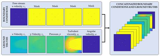
Figure 4.
Boundary conditions and ground truths.
As shown in Figure 4, the five boundary condition channels contain only two pieces of information: the free-stream velocity of the flow, which is always applied in the x-direction, and the location of solid bodies within the flow domain. In the four boundary condition channels that contain only a mask, the solid and fluid regions are delineated as one and zero, respectively. For all other channels with non-zero values in the fluid domain, solid regions are set to zero. The ground truth channels contain the variables that are to be predicted by the CNN; namely, the field variables of x-velocity, y-velocity, pressure, and turbulent viscosity, and the angular velocity of the rotor.
The data pre-processing applied in this study is largely based on the methods outlined in [20]. The steps taken to generate the boundary conditions and ground truths shown in Figure 4 are summarized below. For conciseness, the steps are not presented in their programmed order of execution.
- Since the flow field data exported from the turbine simulations are produced from a non-uniform mesh, the data are interpolated onto a uniform grid. Interpolated variables include x-velocity vx, y-velocity vy, relative total pressure p, turbulent viscosity µt, and wall shear stress τwall. For all channels, a grid resolution of 1024 × 1024 is applied. The wall shear stress data are used to delineate between solid and fluid regions, since non-zero values only occur along the edges of solid bodies and form closed loops. Prior to interpolating the wall shear stress data, the data are binarized by setting all non-zero values to one. This step is performed to enhance the definition of solid edges. By interpolating from the binarized wall shear stress data, solid and fluid regions are tidily set to one and zero, respectively, to produce the mask shown in Figure 5.
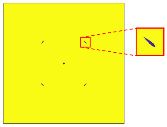 Figure 5. [0, 1] mask produced by the delineation of solid and fluid regions.
 - The [0, 1] mask shown in Figure 5 is used to generate the five boundary condition matrices. To produce the boundary condition channel that that will map onto the x-velocity ground truth, the mask is inverted and multiplied by the free-stream velocity v∞. The remaining four boundary condition channels, which map onto the channels of y-velocity, pressure, turbulent viscosity, and angular velocity, all contain the mask.
- The interpolated x-velocity, y-velocity, and pressure matrices are normalized with respect to the magnitude of the free-stream velocity v∞ as follows:
- To encode the Reynolds number in both the boundary conditions and ground truths, the free-stream velocity, x-velocity, and y-velocity matrices are scaled in the following manner: Firstly, the free-stream velocity is scaled linearly so that the minimum and maximum velocities of 1.0 and 3.0 m/s are made 0.10 and 1.0 m/s, respectively. In order that this scaling be reflected in the ground truths, the x-velocity and y-velocity matrices are scaled by an equivalent factor as the free-stream velocity matrix.
- In CNN-based predictions of flow fields around airfoils, the removal of the offset from the pressure channel has been shown to improve results [20]. To perform this step, the mean of the pressure channel is subtracted from each element i of the matrix. For a normalized pressure matrix with n elements, a zero-offset pressure matrix is obtained as follows:
- Using the exported record of the rotor’s angular position, the angular velocity of the turbine is calculated at each time step. To produce the angular velocity channel, the [0, 1] mask is inverted and multiplied by the computed angular velocity.
- As explained in step one, the ground truth matrices of x-velocity, y-velocity, pressure, and turbulent viscosity were produced by interpolating the exported flow field data onto a uniform grid. Since the exported data only correspond to points within the fluid domain, the boundaries of solid regions are lost in the interpolation process, and solid regions are filled with non-uniform values. To zero all elements within solid regions, the ground truth matrices are multiplied by the inverse of the mask matrix. The non-uniform and zeroed solid regions are depicted in Figure 6.
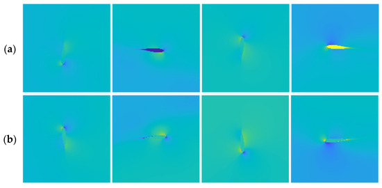 Figure 6. Solid regions with (a) non-uniform values and (b) all data points set to zero.
 - The five boundary condition matrices and five ground truth matrices are concatenated into a single array.
- Each of the five ground truth channels is scaled to the [−1, 1] range, in order to simplify the learning task of the CNN. To achieve this, the maximum absolute value for each channel is determined across all training and testing data, and each channel is then divided by its respective absolute maximum. The boundary condition channel containing the free-stream velocity is scaled by the same factor as the x-velocity ground truth, so that they correlate. The other boundary condition channels are not scaled, as they only contain a [0, 1] mask.
Due to the large dimensions of the produced arrays (10 × 1024 × 1024) and the large quantity of time steps within a single turbine revolution, training and testing data are only prepared for one quarter revolution of each simulation.
2.4. Data Post-Processing
Since the data used to train and test the CNN were normalized and scaled, the outputs of the CNN are processed in the inverse way. Although this post-processing does not affect the percent error in the network predictions, it is required to calculate the absolute difference between the network predictions and the pre-computed ground truths in terms of physical units. To undo the normalization and scaling of the training and testing data, the following steps are executed:
- The [−1, 1] scaling that was applied in step nine of the pre-processing is removed from all channels. This step is applied to the CNN outputs as well as to the ground truths, in order that the discrepancy between them be calculated. To achieve this, each channel is multiplied by its respective scaling factor, i.e., the absolute maximum that was calculated in step nine of the pre-processing.
- The scaling that was applied to encode the Reynolds number in the velocity channels, as described in step four of the pre-processing, is removed. To perform this step, the free-stream velocity channel is scaled linearly so that 0.10 m/s becomes 1.0 m/s, and 1.0 m/s becomes 3.0 m/s. The x-velocity and y-velocity channels are then scaled by the same factor.
- Lastly, to undo step three of the pre-processing, the x-velocity, y-velocity, and pressure channels are denormalized with respect to the magnitude of the free-stream velocity.
2.5. Neural Network Architectures
In order to investigate the effect of data dimensions on prediction error, the following study relies on two CNN architectures: one designed for inputs of size 10 × 1024 × 1024, and the other for inputs of size 10 × 128 × 128. Both architectures are comprised of two key sections: an encoder, which progressively compresses the network input by a factor of two until a 1 × 1 feature map is obtained, and a decoder, which progressively expands the 1 × 1 feature map by a factor of two until the original input dimensions are restored. The compression and expansion of inputs are commonly referred to as down-sampling and up-sampling, respectively.
Since the two networks are used to predict the same unknowns (the flow fields of x-velocity, y-velocity, pressure, and turbulent viscosity, and the angular velocity of the rotor), they both contain five input channels and five output channels. The larger architecture, depicted in Figure 7, features ten down-sampling layers (five layers of 4 × 4 convolution and five layers of 2 × 2 convolution), and ten up-sampling layers (nine layers of up-sampling by nearest-neighbour interpolation, and one layer of 4 × 4 de-convolution). The smaller architecture, depicted in Figure 8, features seven down-sampling layers (two layers of 4 × 4 convolution and five layers of 2 × 2 convolution), and seven up-sampling layers (six layers of up-sampling by bilinear interpolation, and one layer of 4 × 4 de-convolution).
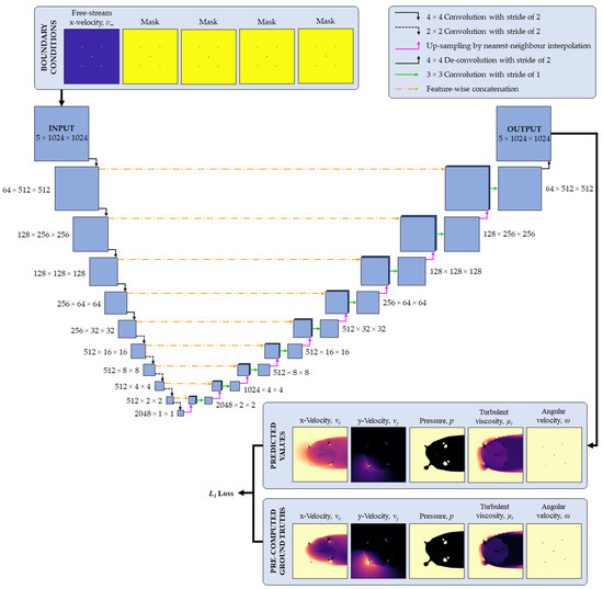
Figure 7.
Large network architecture.
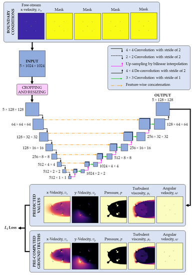
Figure 8.
Small network architecture.
In both architectures, each up-sampling layer is followed by a single convolutional layer that maintains the dimensions of the input it receives. Batch normalization, a technique used in ANNs to augment the accuracy and speed of training [31], is applied to the outputs of convolutional layers in the encoder and decoder, prior to applying non-linear activation functions. In both architectures, the leaky ReLU activation function is applied in the encoder with a slope of 0.2, while the ReLU activation function is applied in the decoder. Both networks also deploy feature-wise concatenation, which consists of stacking equally sized outputs from the encoder and decoder before they are inputted to the next up-sampling layer. The main elements of the CNNs presented in this study are further explained below.
2.5.1. Convolution
Convolutional layers are comprised of filters and biases. Filters, commonly known as kernels, are matrices containing trainable weights. Each filter is accompanied by a bias, which is a single trainable value. In the training of a CNN, weights and biases are fine-tuned through an iterative process of forward and backward propagation. In forward propagation, inputs are processed through the layers of the network to produce outputs, which are then compared to a pre-computed ground truth. In the process of backward propagation, the weights and biases in each layer of the network are adjusted with respect to the gradient of error between them and the final output.
In the process of convolution, a filter convolves across the elements of an input matrix with a specified stride. At each instance, an element-wise multiplication is performed, and the elements of the resultant matrix are summed (these combined operations are hereon denoted by the symbol “*”). The obtained value is then summed with the bias to produce a single element in the output matrix, otherwise known as the compressed feature map. Depending on the choice of input size, filter size, and stride, the dimensions of the input matrix may be maintained or increased. The transformation of an input in a convolutional layer is illustrated in Figure 9.
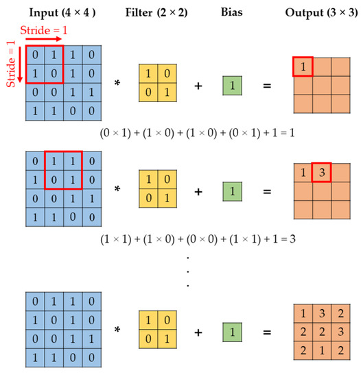
Figure 9.
Convolution.
Convolutional layers can also process an input with multiple channels, i.e., an array, into an output with a single channel. In this type of convolutional layer, the number of filters and biases matches the number of channels in the input array. Using the convolution method illustrated in Figure 9, an output matrix is generated for each channel of the input array. These matrices are then summed to produce the final output of the layer. The processing of a multi-channel input into a single-channel output is illustrated in Figure 10.
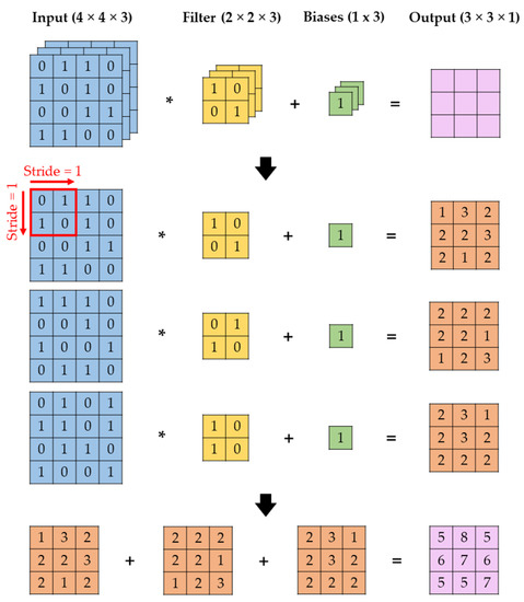
Figure 10.
Convolution for multi-channel inputs.
Another common technique applied in convolutional layers is the padding of input matrices with zeros. This technique is applied to improve the extraction of features around the edges of inputs, as well as to produce the desired output dimensions. The application of a convolutional layer to a zero-padded input is demonstrated in Figure 11.
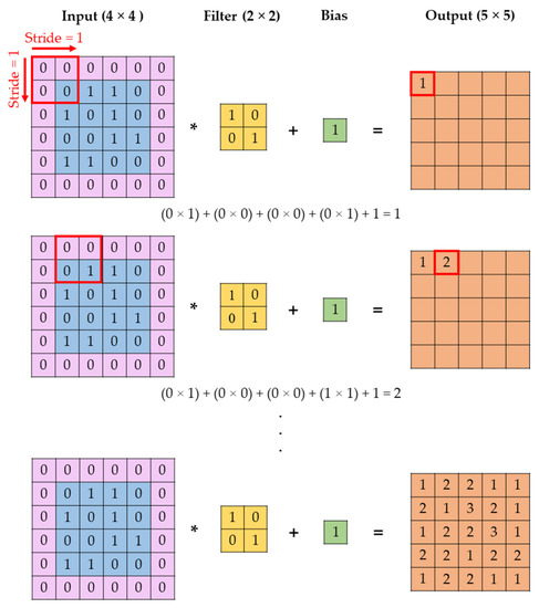
Figure 11.
Convolution with zero padding.
The height and width of the output matrix, denoted as Hout and Wout, respectively, can be calculated based on the dimensions of the input matrix, the thickness of the padding applied to the input, the dimensions of the filter, and the convolutional stride. Denoting the input height, width, and padding thickness as Hin, Win, and P, respectively, and the filter height, width, and convolutional stride as Hf, Wf, and S, respectively, Hout and Wout are calculated as follows:
2.5.2. Up-Sampling by Interpolation
A variety of interpolation techniques are commonly applied in up-sampling layers, including the nearest neighbour, linear, bilinear, bicubic and trilinear methods. In the following work, the nearest neighbour and bilinear interpolation methods are applied in the large and small architectures, respectively.
In the nearest neighbour approach, the dimensions of the input matrix are scaled by a factor n, and the value of each element in the input matrix is applied to n × n elements in the output matrix. The method is depicted in Figure 12, with an assumed scaling factor of two.
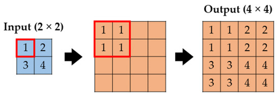
Figure 12.
Up-sampling by nearest-neighbour interpolation.
In the bilinear approach, the dimensions of an input matrix are scaled by a factor n, and the input matrix is stretched so that its corner elements coincide with those of the output matrix. The unknown values in the output matrix are then calculated by repeatedly performing linear interpolation in the vertical and lateral directions. The method is depicted in Figure 13, with an assumed scaling factor of two.

Figure 13.
Up-sampling by bilinear interpolation.
2.5.3. Transposed Convolution
Transposed convolutional layers, or de-convolutional layers, serve the inverse function of convolutional layers. Assuming that the output of a convolutional layer is inputted to a de-convolutional layer with the same filter dimensions and stride, the output of the de-convolutional layer will have the same dimensions as the input to the convolutional layer. In the process of de-convolution, the filter strides over an empty output matrix and is multiplied by a corresponding element of the input matrix at each location. The process is repeated until the filter is multiplied by each element in the input matrix, and the overlapping elements of the resultant matrices are summed to obtain the final output. The process of transposed convolution is depicted in Figure 14.
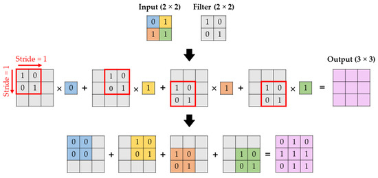
Figure 14.
Transposed convolution.
2.5.4. Activation Functions
Activation functions are used in ANNs to facilitate the learning of complex non-linear patterns [32]. Activation functions are used between the nodes of successive network layers to process the outputs of one layer before they are used as inputs in the next layer, as shown in Figure 15. By modulating the output of each node through a non-linear activation function, the relative importance of each node output is encoded within the network.
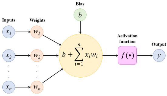
Figure 15.
Application of an activation function between the nodes of successive network layers.
The Rectified Linear Unit (ReLU) and Leaky ReLU activation functions, which are used in the encoder and de-coder sections of the CNNs, respectively, are depicted in Figure 16. In this work, the Leaky ReLU function is applied with a constant slope a of 0.2.
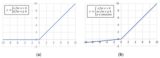
Figure 16.
Non-linear activation functions, (a) ReLU and (b) Leaky ReLU.
2.6. Supervised Training of CNNs
The CNNs developed in this study rely on supervised learning, which is the induction of a model from training data [33]. For networks performing classification, training data consist of labelled data with one or more categorical variables. For networks performing prediction, such as the ones applied in this work, training data consist of pre-computed ground truths with numerical values in a continuous range. Throughout this study, training is performed using the Adam optimization algorithm [34].
2.6.1. Loss Function
In the training of the CNN, the weights and biases of the network are optimized to minimize the mean absolute error between the pre-computed ground truth and the output of the CNN. The mean absolute error, commonly known as the L1 loss, is calculated by summing the absolute error between the corresponding elements of the ground truth and output matrices, and then dividing the total by the number of matrix elements. For a ground truth matrix y and an output matrix a, each having n elements, the L1 loss is calculated as follows:
2.6.2. Training Parameters
Several parameters are adjusted to fine-tune the training of the CNN, including the learning rate, the batch size, and the number of epochs. The learning rate is used within the training optimization algorithm to specify the increment by which weights and biases are adjusted at each iteration of the training process. The batch size specifies the number of training inputs that are submitted to the CNN at one time. An epoch is the processing of the entire training dataset through one cycle of forward and backward propagation. Through numerous epochs, the weights and biases of the network are fine-tuned by the training optimization function.
Training parameters are selected based on the metrics of training loss and validation loss. Training loss, which is calculated after each cycle of forward and backward propagation, is a measure of how well the network is fitting to the training data. Validation loss, which is calculated at the end of each epoch, is a measure of how well the network is fitting to previously unseen data, i.e., data which did not influence the weights and biases of the network. A portion of the training data is reserved for the purpose of validation; in this case, 20% of the dataset. Both the training and validation losses are calculated using the loss function described in the previous section.
2.7. Evaluation Metrics
The performance of the trained CNN models is evaluated with respect to each of the predicted unknowns, which include the flow variables of x-velocity, y-velocity, pressure, and turbulent viscosity, as well as the angular velocity of the turbine. For each network channel, relative error is calculated as the sum of the absolute difference between the elements of the ground truth and output matrices, divided by the sum of the elements in the ground truth matrix. For a ground truth matrix y and an output matrix a, each having n elements, the relative error RE is calculated as follows:
The minimum, maximum, and average relative errors are determined across all testing samples. In order to evaluate the performance of the trained models with respect to different free-stream velocities, the maximum, minimum, and average relative errors are also calculated based on the samples of each individual testing case.
3. Results and Discussion
The following section presents the results of the CFD simulations, as well as the training and testing results of the three developed CNN models.
3.1. URANS Simulations
To generate training and testing data for the CNN, five 2-D URANS simulations were performed in ANSYS Fluent, for the free-stream velocities of 1.0, 1.5, 2.0, 2.5, and 3.0 m/s. The contour plots of x-velocity, y-velocity, relative total pressure, and turbulent viscosity are shown in Figure 17, for the free-stream velocity of 3.0 m/s.
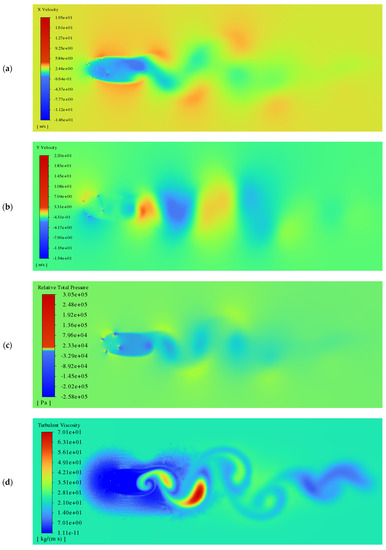
Figure 17.
Turbine wake field at v∞ = 3.0 m/s, for the variables of (a) x-velocity, (b) y-velocity, (c) relative total pressure, and (d) turbulent viscosity.
The flow field around the turbine is shown in greater detail in Figure 18.
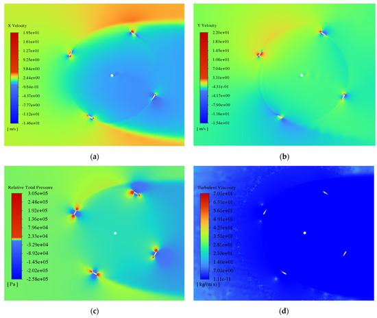
Figure 18.
Flow field around the turbine rotor at v∞ = 3.0 m/s, for the variables of (a) x-velocity, (b) y-velocity, (c) relative total pressure, and (d) turbulent viscosity.
The average angular velocity of the rotor in the 21st revolution is shown in Table 3, for each of the five simulated free-stream velocities.

Table 3.
Average angular velocity of the rotor for each simulated free-stream velocity.
3.2. CNN Training
In this work, three CNN models were developed and compared to investigate how network predictions are influenced by the dimensions of training data and the number of training cases. For each model, training and validation losses were minimized by tuning the parameters of learning rate, batch size, and number of epochs. The datasets and training parameters used to generate each model are detailed in Table 4. Training was performed using an NVIDIA GeForce RTX 6020 GPU.

Table 4.
Datasets and training parameters used to develop each CNN model.
The training and validation loss curves produced for Model 1, Model 2, and Model 3 are depicted in Figure 19, Figure 20 and Figure 21, respectively.
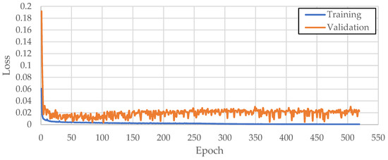
Figure 19.
Training and validation losses produced in Model 1 over 518 epochs.
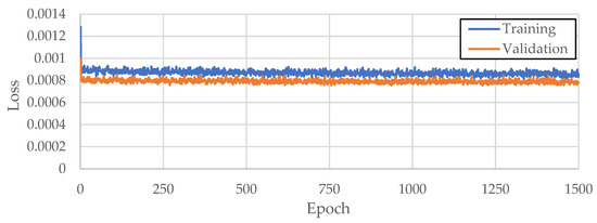
Figure 20.
Training and validation losses produced in Model 2 over 1500 epochs.

Figure 21.
Training and validation losses produced in Model 3 over 1500 epochs.
3.3. CNN Testing
The following section presents the testing results of the three trained CNNs, for each individual testing case.
3.3.1. Model 1: Large Architecture with Two Training Cases
Model 1 was tested using simulation results for the free-stream velocities of 1.5, 2.0, and 2.5 m/s. The minimum, maximum, and average relative errors produced for each testing case are shown in Table 5.

Table 5.
Relative errors produced by Model 1 in each channel, for the individual testing cases of v∞ = 1.5, 2.0, and 2.5 m/s.
From Table 5, it can be observed that the performance of Model 1 varies significantly between the five predicted variables, as well as across the three testing cases. Average relative error is markedly lower in the pressure field than in the velocity and turbulent viscosity fields, although the pressure channel features a substantial maximum error for the testing case of v∞ = 2.0 m/s. The angular velocity of the turbine is well predicted for all testing cases.
The ground truths and network predictions generated for the free-stream velocities of 1.5, 2.0, and 2.5 m/s are shown in Figure 22. For the free-stream velocities of 1.5 and 2.0 m/s, the gradients in the x-velocity, y-velocity, and turbulent viscosity fields are noticeably underpredicted. In contrast, the gradients in the same fields are observably overpredicted for a free-stream velocity of 2.5 m/s. For all three testing cases, a small square region of discontinuity is visible in the x-velocity and turbulent viscosity predictions, around the farthest downstream point of the foil path. In the channel of angular velocity, it can be seen that the foils and rotor shaft are relatively well delineated, albeit with some irregularity.
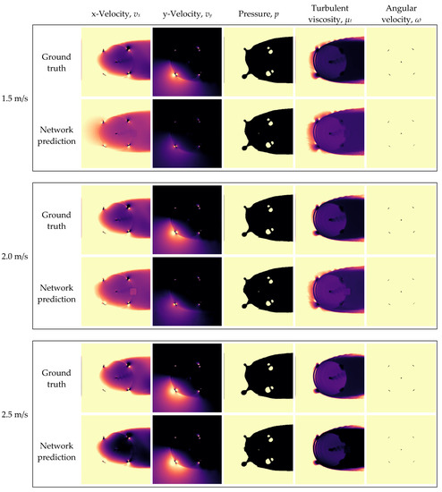
Figure 22.
Ground truths and network predictions of Model 1 for the testing cases of v∞ = 1.5, 2.0, and 2.5 m/s.
3.3.2. Model 2: Small Architecture with Two Training Cases
Model 2 was tested using simulation results for the free-stream velocities of 1.5, 2.0, and 2.5 m/s. The minimum, maximum, and average relative errors produced for each testing case are shown in Table 6.

Table 6.
Relative errors produced by Model 2 in each channel, for the individual testing cases of v∞ = 1.5, 2.0, and 2.5 m/s.
From Table 6, it can be observed that the relative error in each of the flow fields decreases with increasing free-stream velocity. Of the four flow fields, turbulent viscosity is predicted with the smallest and least variable relative error. Across all testing samples, the highest observed relative error (26.7%) occurs in the x-velocity channel, for a free-stream velocity of 1.5 m/s. The angular velocity of the turbine is again well inferred, with a relative error consistently below 2%.
The ground truths and network predictions generated for the free-stream velocities of 1.5, 2.0, and 2.5 m/s are shown in Figure 23. In all testing cases, several discrepancies can be observed. In the channels of x-velocity and turbulent viscosity, it can be seen that the network does not fully replicate the vortex shedding at the turbine shaft. In addition, the rippled wake pattern originating from the upstream arc of the foils appears overly diffuse in the predicted y-velocity and turbulent viscosity fields. The x-velocity is noticeably underestimated upstream of the rotor, and along the leftmost edge of the inferred flow domain. This is especially noticeable for the free-stream velocity of 1.5 m/s. Slight discrepancies can also be seen in the pressure contour plots, at the transition between the light and dark regions.
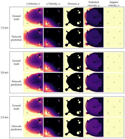
Figure 23.
Ground truths and network predictions of Model 2 for the testing cases of v∞ = 1.5, 2.0, and 2.5 m/s.
3.3.3. Model 3: Small Architecture with Three Training Cases
Model 3 was tested using simulation results for the free-stream velocities of 2.0 and 2.5 m/s. The minimum, maximum, and average relative errors produced for each testing case are shown in Table 7.

Table 7.
Relative errors produced by Model 3 in each channel, for the individual testing cases of v∞ = 2.0 and 2.5 m/s.
From Table 7, it can be seen that Model 3 yields similar results for both testing cases. Across all testing samples, the highest observed relative error (18.0%) occurs in the pressure channel, for a free-stream velocity of 2.0 m/s.
The ground truths and network predictions generated for the free-stream velocities of 2.0 and 2.5 m/s are shown in Figure 24. In the velocity and turbulent viscosity channels, it can be seen that the network does not accurately predict the vortex shedding at the rotor shaft, or the rippled wake pattern emanating from the upstream foil path.
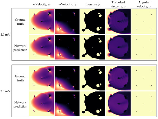
Figure 24.
Ground truths and network predictions of Model 3 for the testing cases of v∞ = 2.0 and 2.5 m/s.
3.4. Comparison of CNN Models
In the following section, the three CNNs developed in this study are quantitatively and qualitatively compared amongst themselves. The data dimensions and training cases applied in the generation of each model are reiterated in Table 8.

Table 8.
Data dimensions and training cases applied in each CNN model.
3.4.1. Comparison of Model 1 and Model 2 (Large vs. Small Data Dimensions)
The effects of training data dimensions can be observed by comparing the results of Model 1 and Model 2. The average relative errors produced by each model are shown in Table 9, based on the combined testing cases of v∞ = 1.5, 2.0, and 2.5 m/s.

Table 9.
Relative errors produced by Model 1 and Model 2, for the combined testing cases of v∞ = 1.5, 2.0, and 2.5 m/s.
As shown in Table 9, the reduction in data size significantly improved results in the channels of x-velocity, y-velocity, and turbulent viscosity, reducing their respective mean relative errors by about 5%, 18%, and 18%. Contrastingly, the mean relative error in the pressure channel increased by roughly 9%. The angular velocity channel was the least impacted, with an increase in mean relative error of about 0.7%. The varied effect of data dimensions on the prediction of the four flow fields is attributable to differences of gradient steepness. Since the pressure field features notably steeper gradients than the velocity and turbulent viscosity fields, it incurs the most significant loss of detail from the reduction in data resolution.
The ground truths and predictions of Model 1 and Model 2 are presented in Figure 25, for the testing case of v∞ = 2.0 m/s. For ease of comparison, the ground truths and predictions of Model 1 have been cropped to match those of Model 2. The ground truths of the two models correspond to the same time step within the same simulation, and appear almost identical. However, the ground truths of Model 2 have a lower resolution. This is most noticeable in the pressure and angular velocity channels, along the boundaries of light and dark regions.
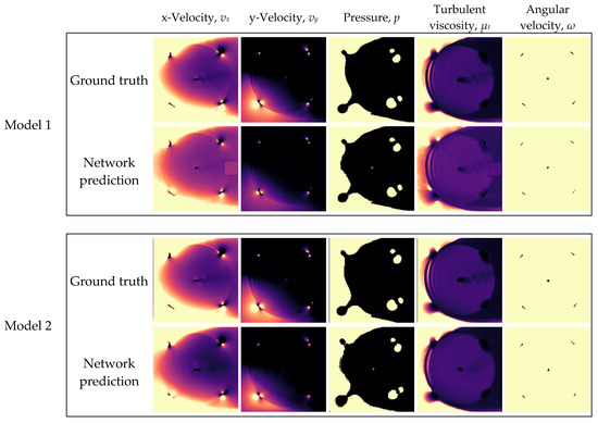
Figure 25.
Ground truths and network predictions of Model 1 and Model 2, for the testing case of v∞ = 2.0 m/s.
From Figure 25, it can be observed that the reduction in data dimensions eliminated the square anomaly occurring along the downstream foil arc, in the x-velocity and turbulent viscosity fields. Although smaller data sizes diminished the relative error in the velocity and turbulent viscosity channels, it also noticeably reduced the definition of some flow features in these fields, including the vortex shedding downstream of the rotor shaft, and the rippled wake pattern left by the cyclic passage of the foils.
3.4.2. Comparison of Model 2 and Model 3 (Two vs. Three Training Cases)
The effects of data diversity can be observed by comparing the results of Model 2 and Model 3. In order that the performance of the models be compared based on identical testing datasets, the results produced by Model 2 for the free-stream velocity of 1.5 m/s are disregarded. The average relative errors produced by each model are shown in Table 10, based on the combined testing cases of v∞ = 2.0 and 2.5 m/s.

Table 10.
Relative errors produced by Model 2 and Model 3, for the combined testing cases of v∞ = 2.0 and 2.5 m/s.
As shown in Table 10, increasing the number of training cases from two to three reduced the minimum, maximum, and average relative errors in all channels. The x-velocity field showed the greatest improvement, with maximum and average relative errors reduced by about 13% and 10%, respectively.
The ground truths and predictions of Model 2 and Model 3 are shown in Figure 26, for the testing case of v∞ = 2.0 m/s. Since the ground truths of the two models are identical, i.e., correspond to the same time step within the same simulation and have the same resolution, they are only shown once.
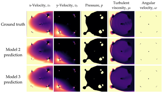
Figure 26.
Ground truths and network predictions of Model 2 and Model 3, for the testing case of v∞ = 2.0 m/s.
From Figure 26, it can be observed that Model 3 better predicts the x-velocity field upstream of the rotor, and also produces smoother transitions between the light and dark regions in the pressure contour plot. The vortex shedding behind the rotor shaft is also slightly better inferred by Model 3, although the trailing edge vortices occurring along the upstream foil arc are slightly better replicated by Model 2.
3.4.3. Comparison of Model 1 and Model 3 (Large Data Dimensions and Two Training Cases vs. Small Data Dimensions and Three Training Cases)
The combined effects of data dimensions and data diversity can be observed by comparing the results of Model 1 and Model 3. In order that the performance of the models be compared based on identical testing datasets, the results produced by Model 1 for the free-stream velocity of 1.5 m/s are omitted. The average relative errors produced by each model are shown in Table 11, based on the combined testing cases of v∞ = 2.0 and 2.5 m/s.

Table 11.
Relative errors produced by Model 1 and Model 3, for the combined testing cases of v∞ = 2.0 and 2.5 m/s.
From Table 11, it can be seen that the combined measures of reducing data size and adding a training case significantly improved predictions in the channels of x-velocity, y-velocity, and turbulent viscosity, lowering their respective mean relative errors by approximately 14%, 18%, and 18%. Although the pressure channel incurred an increase in mean relative error of roughly 1%, the maximum relative error in the channel decreased by about 25%. Predictions of angular velocity were not significantly affected.
The ground truths and predictions of Model 1 and Model 3 are displayed in Figure 27, for the testing case of v∞ = 2.0 m/s. For ease of comparison, the ground truths and predictions of Model 1 have been cropped to match those of Model 3. The ground truths of the two models correspond to the same time step within the same simulation, and appear almost identical. However, the ground truths of Model 3 have a lower resolution. This is most noticeable in the pressure and angular velocity channels, along the boundaries of light and dark regions.
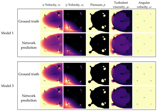
Figure 27.
Ground truths and network predictions of Model 1 and Model 3, for the testing case of v∞ = 2.0 m/s.
From Figure 27, it can be seen that the flow fields predicted by Model 3 are in better agreement with the ground-truths overall, despite the omission of smaller details, such as the vortices produced by the rotor shaft and foils. The substantial differences observed in the results of Model 1 and Model 3 demonstrate how the performance of a CNN can be drastically improved even with two simple changes, i.e., the resizing of training data, and the addition of a training case.
4. Conclusions
In this study, the effectiveness of a deep learning-based turbine modelling method was investigated. Three CNNs were trained to predict the solutions of a 2-D URANS model, for a vertical-axis hydrokinetic turbine operating with flow-driven rotation in free-stream velocities between 1 and 3 m/s. For the boundary conditions of free-stream velocity and rotor position, the flow fields of x-velocity, y-velocity, pressure, and turbulent viscosity were predicted, as well as the angular velocity of the rotor. Training and testing data for the CNNs were derived from the solutions of five URANS simulations, with free-stream velocities of 1.0, 1.5, 2.0, 2.5, and 3.0 m/s. To investigate the effects of training data dimensions, two CNN architectures were developed for data sizes of 10 × 1024 × 1024 and 10 × 128 × 128. In order to assess the effects of data diversity, models were also developed using two and three simulations as training cases. Specifically, one training dataset was based on the free-stream velocities of 1.0 and 3.0 m/s, and the other was based on the free-stream velocities of 1.0, 1.5, and 3.0 m/s.
The effect of data dimensions on prediction error was found to vary significantly for different flow fields. Reducing data dimensions was found to improve predictions of velocity and turbulent viscosity, while worsening predictions of pressure and angular velocity. Using three simulations as training cases instead of two was found to improve predictions of all five unknowns, while the combined measures of reducing data size and increasing data diversity obtained the most favourable results overall. With the best achieved CNN model, the variables of x-velocity, y-velocity, pressure, turbulent viscosity, and angular velocity were predicted with mean relative errors of 6.93%, 9.82%, 10.7%, 7.48%, and 0.817%, respectively.
Based on the results of this study, several recommendations can be made. Firstly, additional research is necessary to improve the concurrent prediction of velocity, pressure, and turbulent viscosity fields, especially over larger flow domains. The effects of data dimensions should be studied in greater detail, and alternative network architectures, feature extraction techniques, and loss functions should be considered. More detailed studies are also necessary to determine how prediction errors vary over the considered range of free-stream velocities, using different numbers and combinations of simulations as training cases. Although the results obtained in this study are not considered rigorous enough for practical application, they highlight the great ability of CNNs to infer complex flow phenomena based on limited training examples.
Author Contributions
Conceptualization, C.D.; methodology, C.D.; formal analysis, C.D.; writing—original draft preparation, C.D.; writing—review and editing, C.D. and E.L.B.; supervision, E.L.B.; project administration, E.L.B.; funding acquisition, E.L.B. All authors have read and agreed to the published version of the manuscript.
Funding
This research was funded by Natural Resources Canada through the Clean Growth Program.
Data Availability Statement
Not applicable.
Acknowledgments
We thank Ali Kerrache for his assistance in using the Grex HPC at the University of Manitoba. Thanks also to Michael Bear from New Energy Corporation for providing details on the EnviroGen 005 Series hydrokinetic turbine. Lastly, thanks to Rahmat Ali for his guidance in the development of the neural network architectures.
Conflicts of Interest
The authors declare no conflict of interest. The funders had no role in the design of the study; in the collection, analyses, or interpretation of data; in the writing of the manuscript; or in the decision to publish the results.
References
- Hau, E. Wind Turbines: Fundamentals, Technologies, Application, Economics, 2nd ed.; Springer: Berlin, Germany, 2006; pp. 586–587. [Google Scholar]
- Dabiri, J.O. Potential order-of-magnitude enhancement of wind farm power density via counter-rotating vertical-axis wind turbine arrays. J. Renew. Sustain. Energy 2011, 3, 043104. [Google Scholar] [CrossRef]
- Ahmadi-Baloutaki, M.; Carriveau, R.; Ting, D.S. A wind tunnel study on the aerodynamic interactions of vertical axis wind turbines in array configurations. Renew. Energy 2016, 96, 904–913. [Google Scholar] [CrossRef]
- Brownstein, I.D.; Wei, N.J.; Dabiri, J.O. Aerodynamically interacting vertical-axis wind turbines: Performance enhancement and three-dimensional flow. Energies 2019, 12, 2724. [Google Scholar] [CrossRef]
- Hezaveh, S.H.; Bou-Zeid, E.; Dabiri, E.; Kinzel, M.; Cortina, G.; Martinelli, L. Increasing the power production of vertical-axis wind-turbine farms using synergistic clustering. Bound.-Layer Meteorol. 2018, 196, 275–296. [Google Scholar] [CrossRef]
- Zhang, J.H.; Lien, F.S.; Yee, E. Investigations of vertical-axis wind-turbine group synergy using an actuator line model. Energies 2022, 15, 6211. [Google Scholar] [CrossRef]
- Hansen, J.T.; Mahak, M.; Tzanakis, I. Numerical modelling and optimization of vertical axis wind turbine pairs: A scale up approach. Renew. Energy 2021, 171, 1371–1381. [Google Scholar] [CrossRef]
- Parneix, N.; Fuchs, R.; Immas, A.; Silvert, F.; Deglaire, P. Efficiency improvement of vertical-axis wind turbines with counter-rotating lay-out. In Proceedings of the EWEA, Hamburg, Germany, 27–29 September 2016; pp. 1–8. [Google Scholar]
- Hara, Y.; Jodai, Y.; Okinaga, T.; Furukawa, M. Numerical analysis of the dynamic interactions between two closely spaced vertical-axis wind turbines. Energies 2021, 14, 2286. [Google Scholar] [CrossRef]
- Cheng, Z.; Madsen, H.A.; Gao, Z.; Moan, T. Aerodynamic modeling of floating vertical axis wind turbines using the actuator cylinder flow method. Energy Procedia 2016, 94, 531–543. [Google Scholar] [CrossRef]
- Ning, A. Actuator cylinder theory for multiple vertical axis wind turbines. Wind Energy Sci. 2016, 1, 327–340. [Google Scholar] [CrossRef]
- De Tavernier, D.; Ferreira, C. An extended actuator cylinder model: Actuator-in-actuator cylinder (AC-squared) model. Wind Energy 2019, 22, 1058–1070. [Google Scholar] [CrossRef]
- Martinez-Ojeda, E.; Solorio Ordaz, F.J.; Sen, M. Vertical-axis wind-turbine computations using a 2D hybrid wake actuator-cylinder model. Wind Energy Sci. 2021, 6, 1061–1077. [Google Scholar] [CrossRef]
- Shives, M.; Crawford, C.; Grovue, S. A tuned actuator cylinder approach for predicting cross-flow turbine performance with wake interaction and channel blockage effects. Int. J. Mar. Energy 2017, 18, 30–56. [Google Scholar] [CrossRef]
- Jégo, L.; Guillou, S.S. Study of a bi-vertical axis turbines farm using the actuator cylinder method. Energies 2021, 14, 5199. [Google Scholar] [CrossRef]
- Bachant, P.; Goude, A.; Wosnik, M. Actuator line modeling of vertical-axis turbines. arXiv 2016, arXiv:1605.01449. [Google Scholar]
- Mohamed, O.S.; Melani, P.F.; Balduzzi, F.; Ferrara, G.; Bianchini, A. An insight on the key factors influencing the accuracy of the actuator line method for use in vertical-axis turbines: Limitations and open challenges. Energy Convers. Manag. 2022, 270, 116249. [Google Scholar] [CrossRef]
- Guo, X.; Li, W.; Iorio, F. Convolutional neural networks for steady flow approximation. In Proceedings of the 22nd ACM SIGKDD international conference on knowledge discovery and data mining, San Francisco, CA, USA, 13–17 August 2016. [Google Scholar]
- Bhatnagar, S.; Afshar, Y.; Pan, S.; Duraisamy, K.; Kaushik, S. Prediction of aerodynamic flow fields using convolutional neural networks. Comput. Mech. 2019, 64, 525–545. [Google Scholar] [CrossRef]
- Thuerey, N.; Weißenow, K.; Prantl, L.; Hu, X. Deep learning methods for Reynolds-averaged Navier–Stokes simulations of airfoil flows. AIAA J. 2020, 58, 25–36. [Google Scholar] [CrossRef]
- Obiols-Sales, O.; Vishnu, A.; Malaya, N.; Chandramowliswharan, A. CFDNet: A deep learning-based accelerator for fluid simulations. In Proceedings of the 34th ACM International Conference on Supercomputing, Barcelona, Spain, 29 June 2020. [Google Scholar]
- Wang, Q.; Zhou, W.; Yang, L.; Huang, K. Comparison between conventional and deep learning-based surrogate models in predicting convective heat transfer performance of U-bend channels. Energy AI 2022, 8, 100140. [Google Scholar] [CrossRef]
- Hennigh, O. Automated design using neural networks and gradient descent. arXiv 2017, arXiv:1710.10352. [Google Scholar]
- Zhang, J.; Zhao, X. Wind farm wake modeling based on deep convolutional conditional generative adversarial network. Energy 2022, 238, 121747. [Google Scholar] [CrossRef]
- Li, R.; Zhang, J.; Zhao, X. Multi-fidelity modeling of wind farm wakes based on a novel super-fidelity network. Energy Convers. Manag. 2022, 270, 116185. [Google Scholar] [CrossRef]
- Li, R.; Zhang, J.; Zhao, X. Dynamic wind farm wake modeling based on a Bilateral Convolutional Neural Network and high-fidelity LES data. Energy 2022, 258, 124845. [Google Scholar] [CrossRef]
- Ti, Z.; Deng, X.W.; Yang, H. Wake modeling of wind turbines using machine learning. Appl. Energy 2020, 257, 114025. [Google Scholar] [CrossRef]
- Menter, F.R.; Langtry, R.B.; Likki, S.R.; Suzen, Y.B.; Huang, P.G.; Völker, S. A correlation-based transition model using local variables―Part I: Model Formulation. J. Turbomach. 2006, 128, 413–422. [Google Scholar] [CrossRef]
- Marsh, P.; Ranmuthugala, D.; Penesis, I.; Thomas, G. The influence of turbulence model and two and three-dimensional domain selection on the simulated performance characteristics of vertical axis tidal turbines. Renew. Energy 2017, 105, 106–116. [Google Scholar] [CrossRef]
- Rezaeiha, A.; Kalkman, I.; Blocken, B. CFD simulation of a vertical axis wind turbine operating at a moderate tip speed ratio: Guidelines for minimum domain size and azimuthal increment. Renew. Energy 2017, 107, 373–385. [Google Scholar] [CrossRef]
- Bjorck, N.; Gomes, C.P.; Selman, B.; Weinberger, K.Q. Understanding batch normalization. Adv. Neural Inf. Process. Syst. 2018, 31, 7694–7705. [Google Scholar]
- Sharma, S.; Sharma, S.; Athaiya, A. Activation functions in neural networks. Towards Data Sci. 2017, 6, 310–316. [Google Scholar] [CrossRef]
- Cunningham, P.; Cord, M.; Delany, S.J. Supervised learning. In Machine Learning Techniques for Multimedia, 1st ed.; Springer Berlin: Heidelberg, Germany, 2008; pp. 21–49. [Google Scholar]
- Kingma, D.P.; Ba, J. Adam: A method for stochastic optimization. arXiv 2014, arXiv:1412.6980. [Google Scholar]
Disclaimer/Publisher’s Note: The statements, opinions and data contained in all publications are solely those of the individual author(s) and contributor(s) and not of MDPI and/or the editor(s). MDPI and/or the editor(s) disclaim responsibility for any injury to people or property resulting from any ideas, methods, instructions or products referred to in the content. |
© 2023 by the authors. Licensee MDPI, Basel, Switzerland. This article is an open access article distributed under the terms and conditions of the Creative Commons Attribution (CC BY) license (https://creativecommons.org/licenses/by/4.0/).