Review

Recent Advancements in Geothermal Energy Piles Performance and Design

1
Materials Science and Engineering Program, College of Arts and Sciences in Collaboration with College of Engineering, American University of Sharjah, Sharjah P.O. Box 26666, United Arab Emirates
2
Department of Civil Engineering, American University of Sharjah, Sharjah P.O. Box 26666, United Arab Emirates
3
Department of Geotechnical Engineering, AECOM, Calgary, AB T2C 5E7, Canada
4
Department of Computer Engineering, School of Engineering, University of San Carlos, Cebu 6000, Philippines
5
Department of Biology, Chemistry and Environmental Sciences, American University of Sharjah, Sharjah P.O. Box 26666, United Arab Emirates
*
Author to whom correspondence should be addressed.
Energies 2024, 17(14), 3386; https://doi.org/10.3390/en17143386
Submission received: 20 May 2024 / Revised: 1 July 2024 / Accepted: 5 July 2024 / Published: 10 July 2024
(This article belongs to the Special Issue Review of Geothermal Energy Production)

Abstract

:
Geothermal energy piles or ground heat exchange (GHE) systems embrace a sustainable source of energy that utilizes the geothermal energy naturally found inside the ground in order to heat and/or cool buildings. GHE is a highly innovative system that consists of energy loops within foundation elements (shallow foundations or piles) through which a heat carrier fluid circulates, enabling heat extraction or storage in the ground. Despite the innovation and potential of GHE systems, there are significant challenges in harmonizing their thermal and mechanical designs due to the complex interactions involved. This review critically examines state-of-the-art design methodologies developed to address these complexities, providing insights into the most recent advancements in GHE performance and design. Key findings include innovative techniques such as advanced numerical modeling to predict thermomechanical behavior, the use of different pipe configurations to optimize heat transfer, and strategies to minimize thermal stress on the foundation. Additionally, this review identifies research gaps, including the need for more comprehensive full-scale experimental validations, the impact of soil properties on system performance, and the long-term effects of thermal cycling on pile integrity. These insights aim to contribute to a better understanding of the thermomechanical behavior of energy piles, ultimately facilitating more accurate and effective design solutions.

1. Introduction

The pile foundation is widely used to encounter the heavy loads of the superstructures. Numerous studies have been conducted to assess the behavior of piles and soils surrounding them [1,2,3,4,5,6,7,8,9,10,11]. Buildings consume approximately half of all energy consumed globally; therefore, using piles for geothermal applications is a sustainable option. The building cooling systems, i.e., air conditioning, in the United Arab Emirates (UAE) consume more than 60% of the UAE total energy due to the high temperatures that the Gulf region experience during the summer period [12,13]. Furthermore, the building sector in the US consumes about 76% electricity and 40% of primary energy which contributes to a relatively high percentage of greenhouse gases (GHGs) such carbon dioxide (CO2) [14]. Thus, sustainable systems that contribute to the global CO2 reduction are highly recommended. Geothermal energy foundation systems are found to be applicable for most of the substructures’ (structure under the ground level) foundation systems, i.e., shallow foundation and deep foundation (piles) [15]. The energy pile foundation system is the most common application of geothermal energy systems. The objective of the energy pile system is to produce multiple heating and cooling loops to cover building energy needs during winter and summer periods, respectively. The system consists of an embedding heat transfer system (i.e., heat pump) in the pile foundation to extract or inject heat from or into the surrounded soil, which covers the required energy of a building [16,17,18,19,20,21,22]. Figure 1 illustrates the publication trends over the past 17 years regarding geothermal energy pile systems, while Figure 2 presents a graphical map of the most relevant keywords to this study.
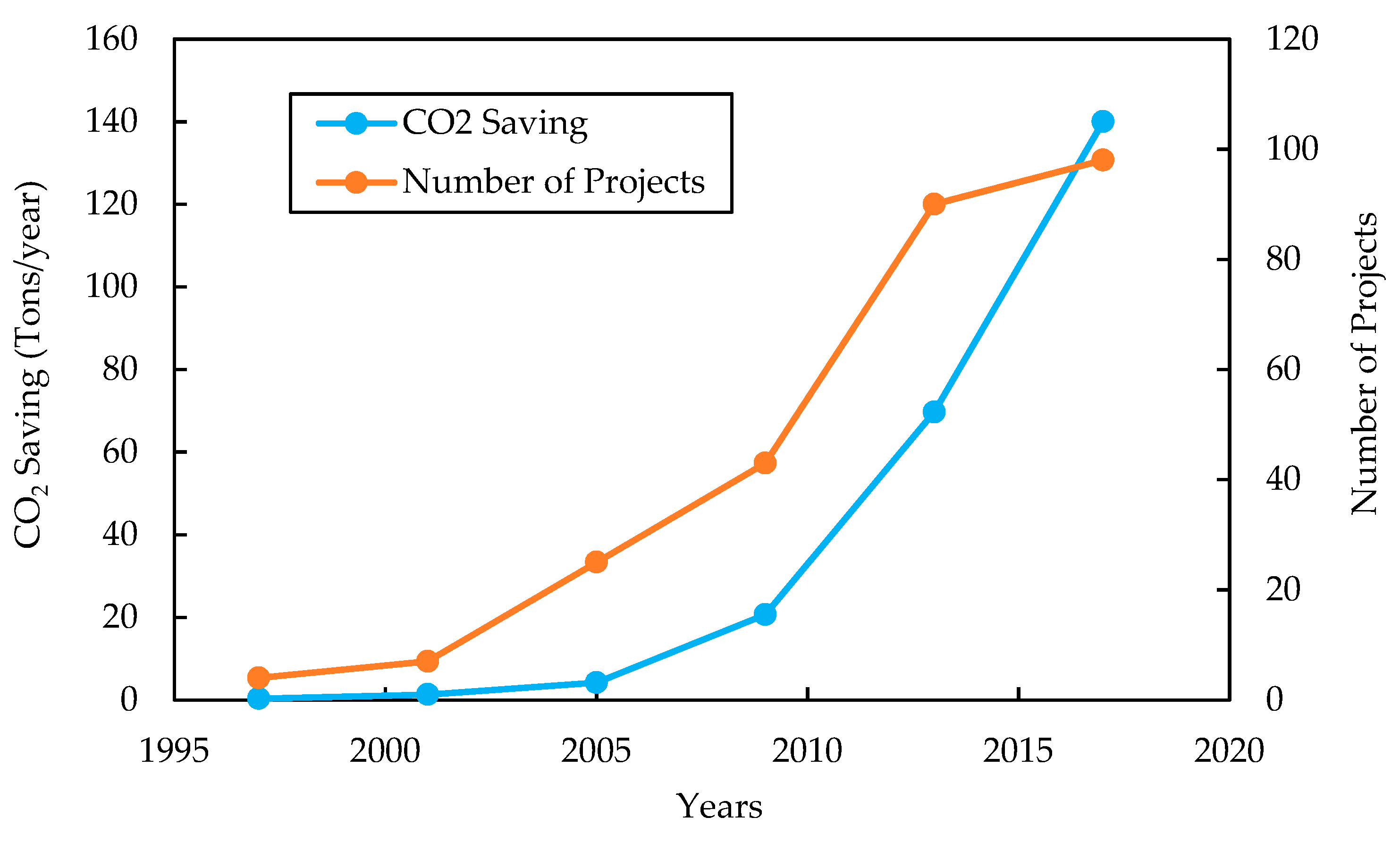
Recently, several energy substructures projects, including the Laizer tunnel in Austria, Keble Collage in Oxford (UK), and Zurich Airport in Switzerland, have utilized this innovative “green” technology to heat and cool the structures during winter and summer seasons, respectively [15,24,25,26,27,28,29]. From the statistical point of view, all these energy geo-structure projects have shown to reduce harmful emissions such CO2 (Figure 3). The stability of subsurface temperature below 50 m owing energy pile, or the so-called ground heat exchanger (GHE), is the most common application of the geothermal technology among all other substructure applications. Therefore, extracting or injecting heat from/to the ground is applicable in the application of energy piles, which has led to the rapid spread of this technology, especially in Austria and the UK. In addition to the energy pile stability, its installation is nevertheless facing considerable challenges due to the complication of thermal–geotechnical interaction [24,30,31,32,33,34,35].
The purpose of this review study is to present a concise summary of the recent and most significant advances in the literature concerning the performance of energy piles and their design that includes results of the most recent experimental, analytical, and numerical research on energy pile design. Furthermore, this paper summarizes the state-of-the-art understanding of the thermal and thermomechanical behavior of energy pile systems. Accordingly, this review should aid in the understanding of the complex interaction between thermal and mechanical responses of the geothermal system, giving rise to the difficulty of designing energy pile systems. Additionally, a section on system development and applications is included in this paper to offer a broader perspective on the adaptation of geothermal energy systems to diverse climates and geological conditions worldwide. Furthermore, this study will assist in tackling or overcoming the limitations of current research, which will subsequently lead to a more accurate design of energy pile systems.

2. Background and Literature Review

Several in situ and laboratory-based studies have been conducted to assess the energy pile performance and to identify the thermomechanical behavior of energy piles. Simultaneously, several review papers have summarized the current state of knowledge of energy piles [11,16,17,18,19,37,38,39,40,41]. Additionally, available optimization methods for the thermomechanical systems, i.e., energy piles, and attempts to optimize the design of energy pile through tuning various aspects such as environmental, mechanical, and economical aspects have also been reviewed [42]. However, few studies have summarized the current research needs. Therefore, the main purpose of this paper is to review the energy pile performance and design, along with current research gaps in this research area.
In order to properly design energy pile systems, an appropriate understanding of the heat transfer is required. Despite the difference between energy piles and boreholes systems, they both have the same thermal process. The following three stages summarize the thermal process of energy piles or borehole systems: (1) heat transfer through the ground, (2) thermal transfer through the concrete material (pile material) and the embedded heat exchanger pipes, and (3) the heat transfer through internal thermal fluid and inner surface of the embedded pipes (Figure 4).
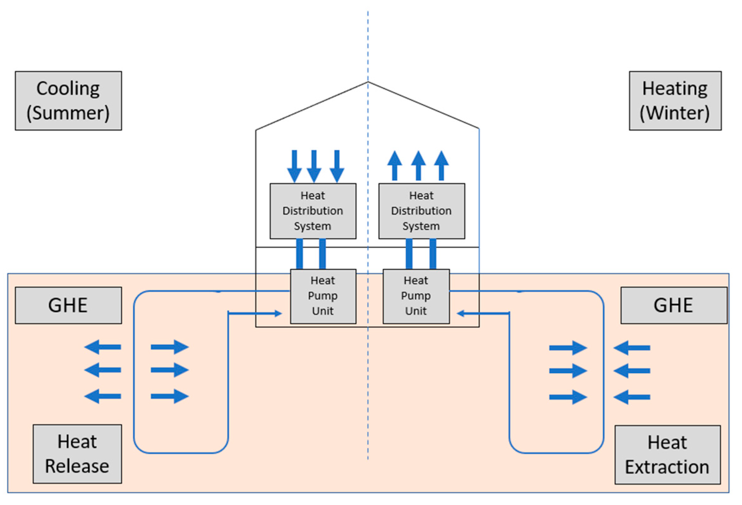
Three major components are responsible for the heat transfer process: (1) the ground heat exchanger (GHE), (2) the heat pump, and (3) the heat transfer subsystem. Figure 5 provides a schematic of the energy pile system. The function of these heat transfer elements varies with the seasons. In winter, the soil temperature is typically higher than the air temperature, as illustrated in the right half of Figure 5, where the heat extraction process occurs. Conversely, during hot weather seasons, the soil surface temperatures tend to be lower than the air temperatures, as shown in the left half of Figure 5, where the heat release process takes place. This demonstrates the function of the GHE system in transferring heat from the ground to the building during winter and from the building to the ground during summer.

3. Thermo and Thermomechanical Behaviors of Energy Piles

3.1. Analytical Methods

The designed methods for the borehole heat exchangers (BHEs) are usually used by analytical methods. The heat transfers among ground heat exchangers under steady-flux conditions have been investigated by several researchers. By introducing the theory of thermal resistance, which is parallel to the concept of electrical resistance, the process of analyzing GHEs under steady-flux conditions becomes easy to examine. Loveridge et al. [45] conducted research on two- and three-dimensional models to obtain the thermal resistance using steady-state principles. The outcomes of the study presented principal methods that can evaluate the thermal resistance of GHE pipes. Yet, these methods can lead to uncertainty in the system’s thermal prediction due to overprediction of temperature changes underground resulting from the application of a time-dependent approach, since the process of heat transfer within an energy pile is transient. A number of research groups have performed studies which depend on the derivation of the G-function theory [46,47]. Their studies have resulted in models that can calculate the temperature change of a vertical heat source surrounded by uniform ground such as cylindrical heat source models (CSM) and line heat source models (LSMs). For the analysis of energy piles and boreholes, several model configurations (i.e., model of infinite ring, finite ring, infinite spiral, and finite spiral) were obtained to account for low computational time and simplicity [42]. Deqi et al. [48] conducted a study to numerically examine the limitation of the homogeneous analytical models developed for energy piles [48]. The study reported that an incorrect evaluation of heat transfer, especially for large-diameter piles, and in short-term operation, may occur as a result of the assumption of a homogenous domain [49].
Additionally, the influence of the backfill material’s thermal mass, which can be significant for energy piles of sizeable concrete volume, is not integrated in the developed models. Park et al. conducted research to analyze the performance of energy piles in short-term periods. The study reported that the concrete’s thermal capacity is considered a major element that can affect the thermal performance of energy piles [50]. This denotes the value of accurately specifying the thermal storage of heat within the pile concrete, in addition to the cruciality of including it into analytical analysis and the design software of energy piles. To consider this characteristic, the cylindrical source model was improved [47]. This depicts a more accurate analysis of pile heat exchangers with respect to the classical models for long-term response; particularly since the temperature curve leans towards steady-state distribution.
Furthermore, the model employs uniform material characteristics for both ground and concrete and it also overlooks the GHE geometry. Many researchers have examined spiral heat exchangers analytically. Cui et al. [51] investigated the transient thermal conduction around energy piles, leading to the development of the ring-coil heat source model (RSM). This model, which used helical coils, served as a criterion for analyzing transient thermal conduction around energy piles. An alternative model, based on a cylindrical heat source, was developed; it simplifies the spiral tubes into several rings and ignores the influence of the pile. Man et al. [47] addressed a few of the limitations of the ring model by treating the heat exchangers as a spiral line, where every pitch portion distributes heat. Additionally, a novel energy pile technology that incorporates phase change material (PCM) into concrete piles has been proposed by Han and Yu [52] to enhance thermal energy extraction. This new approach has shown significant improvement in geothermal energy extraction and has potential applications for snow melting on bridge decks across diverse climate regions in the U.S [52].

3.2. Numerical Methods

The thermal performance of the energy pile could also be assessed numerically. Recently, there have been several studies that predict the energy pile performance using the finite element modeling (FEM) and finite volume method (FVM) [53,54,55,56]. Furthermore, several reviews were conducted to capture numerical evaluation of the energy piles [19,37,56,57]. The numerical determination of energy pile behavior is found to be accurate and realistic. Accurate determination of the system component, material, and the boundary condition are crucial for energy pile simulation. One of the advantages of utilizing the numerical method in order to predict the energy pile behavior is that it can simulate the fluid flow and simulate the temperature degradation along the pile depth. Furthermore, the effect of ground water is also predictable when using the numerical method along with the water movement through the soil and different soil strata. Also, the numerical method can account for different soil layers and it controls the thermal capacities of different pile elements.
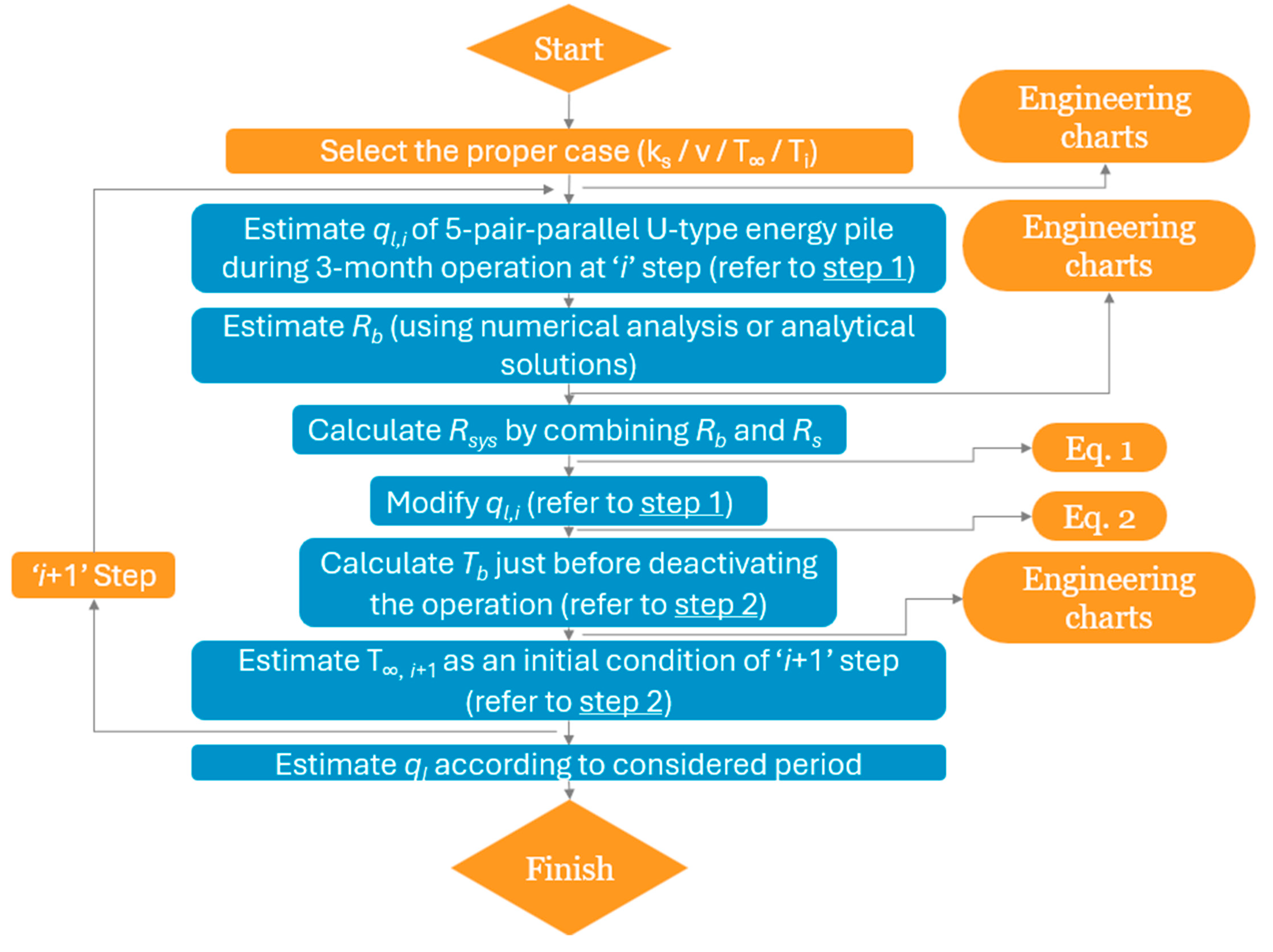
Bezyan et al. [58,59] predicted the heat transfer performance of the energy piles using three-dimensional numerical models. To avoid high computational time due to the detailed discretization of highly complex models, several researchers have adapted simplified models to reduce the computational time [43,58,60,61,62,63]. An engineering chart conducted by Park et al. [50] was adapted based on parametric studies using several numerical models. The flow chart, as displayed in Figure 6, serves as a condensed representation of the essential design steps required for evaluating the heat transfer characteristics of energy piles. However, regrettably, it does contain some notable inaccuracies. Therefore, it is recommended to obtain other parametric studies that address a larger number of design parameters.
The flow chart presented in Figure 6 displays several key parameters denoted as symbols K s   , υ ,     T , and T i . These symbols represent specific aspects related to the thermal characteristics of the system. K s stands for the thermal conductivity of the soil (measured in W/mK), υ represents the flow rate of the working fluid (measured in gallons per minute, equivalent to 3.79 L per minute), T corresponds to the initial ground temperature in Kelvin, and T i signifies the inlet fluid temperature in Kelvin. Furthermore, the symbol “ɋ” in the flow chart represents the heat exchange rate per unit length of the energy pile. Consideration is given to a scenario involving two energy piles, namely, pile A and pile B, each with distinct thermal resistance values for the system denoted as Rsys. Within this context, Rb represents the thermal resistance of the borehole, while Rs represents the thermal resistance of the soil.
In Figure 6, Step 1 involves estimating the thermal performance of an energy pile over a 3-month operation period. Additionally, Step 2 focuses on estimating the long-term thermal performance of cast-in-place energy piles over an operating period exceeding one year, considering changes in ground temperature.
Given the values of heat exchange rate of energy pile A ( ɋ 1 A ) and Rsys, it is possible to estimate the heat exchange rate of energy pile B ( ɋ 1 B ) using Equation (1). Notably, the heat exchange rate of energy pile A ( ɋ 1 A ), characterized as a 5-pair parallel U-type energy pile, can be determined using the engineering chart. Consequently, the heat exchange rate of energy pile B ( ɋ 1 B ) can be evaluated. It is important to highlight that the engineering charts referenced in the flow chart can be found in the work by Park et al. [50].
ɋ 1 B = ( 2 C M   Rsys + L A 2 C M   Rsys + L B ) ɋ 1 A
Equation (1) involves the following variables: L, which represents the length of the energy pile in meters; M, denoting the mass flux of the circulating fluid in kilograms per second; and C, signifying the specific heat of the circulating fluid, measured in joules per kilogram Kelvin.
T b , which is defined by Equation (2), represents the average temperature along the circumference of the borehole walls (measured in Kelvin).
T b = T i , f ( ɋ 1 L 2 C M   ) R B ɋ 1
where T i , f denotes the inlet fluid temperature in Kelvin, and RB characterizes the convective resistance between the fluid and the pipe wall, as determined by Equation (3).
R B = T f , m T b ɋ 1  

3.3. Experimental Tests

Most researchers in the field are preferring numerical work over experimental testing, especially those predicting the thermomechanical behavior of the energy pile, due to the complications and cost- and time-consuming nature of the experimental testing. However, the numerical model reliability highly depends on accurate material constitutive relationships and the boundary conditions defined in the model. Therefore, it is always wise to incorporate full-scale testing to achieve reliable detection of the energy pile thermomechanical behavior. Figure 7 depicts a relationship between ground depth and the prediction of thermal-induced stresses using an experimental setup.
Numerous studies have focused on and summarized the research statuses of the laboratory and the field thermomechanical experimental tests [64,65,66,67,68,69,70]. Cecinato et al. [70] stated that the large size of the experimental samples may be an advantageous factor from the energy-exchange potential perspective, which enhances accurate thermal analysis. Furthermore, Jiang et al. [68] reviewed 12 experimental tests in full-scale, which are used to predict the thermomechanical behavior of the driven energy piles.
Full-scale experiments give a better indication of the energy pile thermal and machine behaviors [71]. In contrast, either finite element method or finite difference method (numerical methods) are suitable to detect the thermal, mechanical, and thermomechanical behaviors of the energy piles. Hence, numerical methods are alternatives for the onsite experiments. Table 1 summarizes recent studies conducted on energy piles.

4. Results and Discussion

4.1. Pile Design

To a certain extent, the larger pile geometry has a positive impact on the energy pile efficiency, as it enables more interaction with the soil. Furthermore, increasing the pile size allows more ground heat exchangers (thermal pipes) to fit inside the pile, which reduces the pile thermal resistance and enhances the heat transfer process. However, improving the thermal efficiency of the energy pile due to increasing the pile geometry increases the axial stresses on the foundation system. Moreover, an increase in the pile length and/or diameter prevents the pile-to-pile interaction [39]. Consequently, increasing the pile geometry requires an accurate design from the mechanical perspective [75].

4.2. Ground Heat Exchanger Tube Design

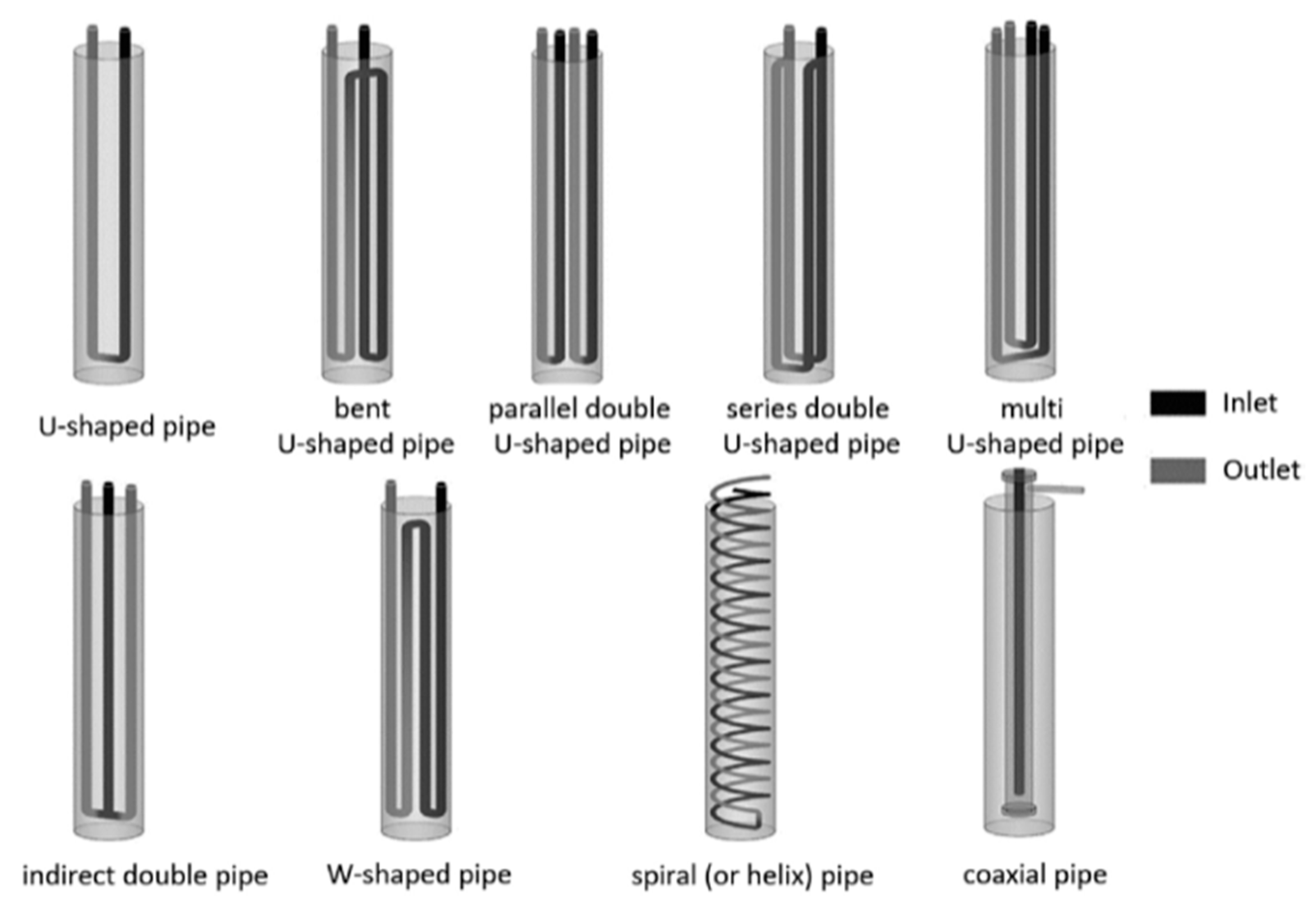
In general, the ground heat exchanger consists of inlet and outlet tubes which are used to exchange the heat with the surrounding soil using a certain liquid, typically water and antifreeze solutions. The diameter of the tubes ranges between 20 mm and 40 mm [76] and are made from polyethylene pipes [77]. The tube size depends on the depth of the energy pile system i.e., it is not economical to use a large tube diameter for shallow energy pile systems due to the additional unnecessary power required for large-diameter tubes [78]. Either in borehole or in energy pile systems, the tubes are installed vertically and can be shaped into individuals a or series of U-shape, W-shape, coaxial, or spiral shapes (Figure 8). The multiple series of the U-shape and the W-shape are typically used to increase the energy pile effectiveness of heat exchange. These shapes are typically fixed to the pile’s reinforcement. The fluid uses these tubes as a pathway.
The shape of the pipe is generally tuning the thermal performance of the energy pile system. During the past three decades, among all the pipe configurations, the single U-shape followed by the single W-shape have been selected as the most used heat ground exchangers in the energy pile system. Owing to the simplicity of the U-shape, heat exchanger design, and ease of installation and transportation, U-shape have been selected as the standard commercial configuration [77]. On the other hand, the W-shape heat exchanger showed a higher thermal storage in the energy piles system compared to the U-shape pipes [24,79]. Due to the complication of the W-shape installation process, it is less commercialized in comparison to U-tube. Furthermore, the configuration of W-shape consists of typically locking the air at the top of the tube. The spiral configuration, therefore, is favorable to researchers due to its application in preventing air accumulation. Furthermore, the spiral shape has shown the highest heat transfer performance in short timescales [80], which encouraged some researchers to regard it as the best configuration [47,53]. To the authors’ knowledge, the most common shear reinforcement of the conventical pile is the spiral reinforcement. Hence, the matching between the shape of pile confinement reinforcement (shear reinforcement) and the spiral heat exchanger might contribute to its implementation.
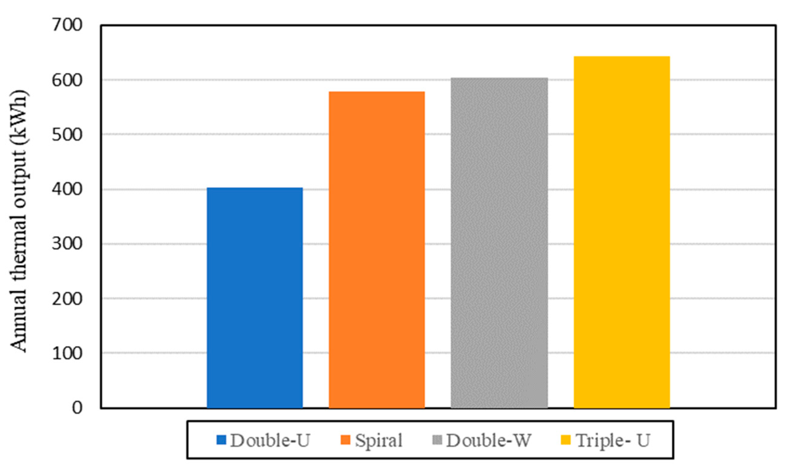
According to Luo et al. [81], who tested the thermal production of different tube configurations after a full year of operation (Figure 9), the results indicated that the triple U-shape obtained the highest annual thermal output, followed by the double W-shape. The spiral configuration showed a 10% reduction in thermal production compared to the triple U-shape and a 4% reduction compared to the double W-shape. Furthermore, the spiral configuration exhibited almost a 50% increase in annual thermal output compared to the double U-shape.
In recent research conducted by Kong et al. [5], an investigation into heat distribution was carried out using various tube configurations (U-, W-, and 4U-shaped pipes) at a depth of 12 m over a duration of 336 h. Their findings indicated that there was nonuniformity in the distribution of temperature and thermal stress within the cross-sections (circular cross-section with diameter of 0.6 m) of energy piles, with variations attributed to the specific heat exchange pipe configurations. Figure 10 visually illustrates the temperature distribution for the different pipe configurations examined in Kong et al.’s study [5]. According to the observations in Figure 10, it can be concluded that the type of heat exchanger significantly influenced the temperature distribution within the energy piles. Each configuration resulted in different patterns of nonuniform temperature increases across the pile cross-sections [5].
Despite the difficulties associated with the installation of the helix shape, especially in small-diameter piles [75], the thermal performance of the helix shape showed the optimal configuration for a large-diameter energy pile. Furthermore, the helix shape displayed a better thermal performance compared to the quintuple U-shape [49]. However, limitations are found in the application of helix configuration.
The sublayer profile properties are the fundamentals of any geo-structure design. Soil parameters such as elastic modulus (E), soil thermal conductivity, ground temperature, ground thermal expansion, and the depth of the groundwater table are the baseline aspects used to characterize the thermal behavior of the ground profile during the operation of the energy pile system. Therefore, an accurate determination of these parameters is essentially required in order to obtain the most effective thermal performance of the energy pile system. The risk of overestimating or underestimating the aforementioned parameters drastically increases when an unbalanced loop of heating/cooling occurs during the operation of the system [82]
Moradshahi [83] conducted a parametric study to experimentally investigate the influence of varying soil thermal parameters, such as the thermal expansion and the thermal conductivity along with the elastic modulus (soil stiffness index). Furthermore, they obtained a numerical validation to examine their experimental results. Moradshahi [83] indicated that the soil stiffness index is the most effective parameter on the thermal stresses of the energy pile compared to the aforementioned soil thermal properties.
From the heat transfer perspective, the presence of a water table is also critical. An experimental study obtained by Vickers [84] indicated that as the groundwater flows, an increase in the soil conductivity, in addition to an increase in heat transfer, is obtained.

4.3. System Development and Applications

Geothermal energy pile systems have been effectively developed and adapted to various climates and geological conditions worldwide. For instance, the application of geothermal technology has seen significant growth across Europe, with notable progress in countries such as Sweden, Germany, France, Switzerland, and Norway [85]. Despite this overall advancement, there was a marked variation in both absolute numbers and growth rates between these nations [85].
Major contributors to global geothermal production include the United States, the Philippines, Indonesia, Mexico, Italy, New Zealand, Iceland, and Japan, collectively accounting for approximately 91% of the world’s geothermal output [86]. However, challenges persist, particularly in countries like India, where policy definition for geothermal exploitation remains a barrier [86]. The worldwide utilization of geothermal energy spans over 80 countries, with rapid development observed in regions with favorable geological conditions, such as Iceland, Kenya, New Zealand, and Turkey [87,88]. Despite this broad application, several challenges delay further geothermal development. These include managerial, technical, and regulatory obstacles, as well as the high capital cost, inherent risks associated with exploration and drilling, and opposition by local communities [89,90]. To address these challenges, it has been recommended to implement policy changes, enhance human resource development, and facilitate the transfer of technology [91].
In the Arab region, countries such as Egypt, UAE, and Saudi Arabia are actively exploring geothermal energy as a viable renewable resource. Saudi Arabia has launched a strategic plan to diversify its energy sources, emphasizing the development of geothermal energy in the western and southwestern regions along the Red Sea area [92]. Similarly, the Gulf of Suez (GOS), northwestern arm of the Red Sea between Africa (west) and the Sinai Peninsula (east) of Egypt, has been identified as a promising site for geothermal power generation [93] due to the fact that this area is part of the active plate boundaries that separate Africa-Nubia, Arabia, and Sinai, and is currently undergoing extension, making it especially conducive to geothermal development, with its distinct high-temperature zones offering significant potential for geothermal energy production. These geological and tectonic characteristics make the region ideal for geothermal development [93,94].
In the United Arab Emirates (UAE), research has investigated the feasibility of using geothermal energy to meet substantial electricity demands for cooling purposes. A ground source heat pump system has been designed and tested through parametric studies and modeling simulations, demonstrating its potential effectiveness [95]. Additionally, another study in the UAE proposed converting abandoned oil and gas wells into subsurface geothermal recovery points, highlighting the potential for clean energy generation from these thermal reserves [96].
According to a recent study by Eiger and Akar [97], the global geothermal power market is currently in its third stage of development, with potential for entering a fourth developmental peak. However, the most significant barrier to this continued growth remains the risks tied to exploration and drilling.

5. Conclusions

The purpose of this review was to provide a brief yet full synopsis on energy pile performance and its design and assessment. The difficulty of the design of the energy pile system is owed to the complex interaction between thermal and mechanical responses of the geothermal system. A mini review was conducted that summarizes the state-of-the-art understanding about the thermal and thermomechanical behaviors of energy pile systems. Furthermore, this paper reviewed the main results of the most recent experimental, analytical, and numerical research on the design of energy piles.
The major review findings and perspectives are the following:
  • Numerical-based studies are highly recommended in this area of research as the experimental studies are indeed accurate, but also time- and cost-consuming, since the computational time is significantly high for the full numerical model. To avoid high computational time and obtain an accurate simulation assumption, experimental validation is necessary. A comprehensive study that involves finite element modeling (FEM) and finite volume modeling (FVM) is required to achieve accurate thermomechanical behavior of the energy pile. Therefore, combining the structural and fluid dynamic analyses obtained from FEM and FVM, respectively, provides an enhanced outlook and a better understanding of the actual behavior of energy pile systems during and after system operation.
  • In modeling, the pile boundary conditions highly affect the distribution of the thermal stresses. For this reason, a proper definition of the pile rigidity is extremely suggested due to the fact that it might either underestimate or overestimate the design of the energy pile system. The thermally induced stresses also depend on the applied mechanical load since an irreversible settlement occurs between 30% and 40% of the ultimate pile resistance.
  • A detailed thermomechanical analysis is decidedly necessary to obtain accurate pile constraints under service and ultimate loads for single piles and groups of piles. It is important to note that the pile-to-pile interaction must be incorporated in the thermomechanical analysis of the group of piles. Furthermore, a detailed investigation of pile-to-pile interaction is required to configure the best positions of the piles and to detect the minimum number of piles required.
  • Geothermal energy pile systems have been effectively adapted to various climates and geological conditions worldwide, with significant progress in Europe and major contributions from countries like the United States, the Philippines, and Iceland. However, challenges such as high capital costs, exploration risks, and regulatory obstacles persist, necessitating policy changes, enhanced human resource development, and technology transfer to further advance geothermal development globally.

Author Contributions

Conceptualization, A.K., M.A., O.M.E.-K. and P.V.A.; methodology, A.K., M.A. and O.M.E.-K.; software, A.K. and P.V.A.; validation, M.A., Z.K., O.M.E.-K. and P.V.A.; formal analysis, A.K., M.A. and O.M.E.-K.; investigation, M.A., Z.K., O.M.E.-K. and A.K.; resources, M.A., Z.K. and O.M.E.-K.; data curation, A.K.; writing—original draft preparation, A.K. and M.A.; writing—review and editing, A.K., M.A., Z.K., O.M.E.-K. and P.V.A.; visualization, A.K., M.A., Z.K., O.M.E.-K. and P.V.A.; supervision, M.A., Z.K. and O.M.E.-K.; project administration, M.A., Z.K. and O.M.E.-K.; funding acquisition, M.A. and O.M.E.-K. All authors have read and agreed to the published version of the manuscript.

Funding

This research was financially supported by the American University of Sharjah (AUS) through the Ph.D. in Material Science and Engineering (Ph.D.–MSE) Program, and the Open Access Program (OAP).

Data Availability Statement

Not applicable.

Acknowledgments

The authors greatly appreciate the financial support offered by the Faculty Research Program at AUS. This paper represents the opinions of the authors and does not mean to represent the position or opinions of the AUS.

Conflicts of Interest

Author Zahid Khan was employed by the company AECOM. The remaining authors declare that the research was conducted in the absence of any commercial or financial relationships that could be construed as a potential conflict of interest. The funders had no role in the design of the study; in the collection, analyses, or interpretation of data; in the writing of the manuscript, or in the decision to publish the results. This paper represents the opinions of the author(s) and does not mean to represent the position or opinions of the American University of Sharjah.

References

  1. Khalil, A.; Khan, Z.H.; Attom, M.; El Emam, M.; Fattah, K. Dynamic Properties of Calcareous Sands from Urban Areas of Abu Dhabi. Appl. Sci. 2022, 12, 3325. [Google Scholar] [CrossRef]
  2. Wang, G.; Hong, B.; Liu, X.; Sun, D.; Shao, Z.; Yao, Y. Experimental Study on the Shear Properties of Soil around Piles with Permeation Grouting. Appl. Sci. 2023, 13, 621. [Google Scholar] [CrossRef]
  3. Xu, L.; Qi, C.; Niu, L.; Ding, X. Effect of Expanded Body Diameter on the Soil Surrounding a Pile Based on the Half-Face Pile Model Test of Undisturbed Soil. Buildings 2023, 13, 951. [Google Scholar] [CrossRef]
  4. Lin, C.; Huang, L.; Chen, S.; Huang, M.; Wang, R.; Tan, Q. Study on Shielding Effect of the Pile Group in a Soft-Soil Foundation. Appl. Sci. 2023, 13, 9478. [Google Scholar] [CrossRef]
  5. Kong, G.; Fang, J.; Lv, Z.; Yang, Q. Effects of pile and soil properties on thermally induced mechanical responses of energy piles. Comput. Geotech. 2023, 154, 105176. [Google Scholar] [CrossRef]
  6. Khalil, A.; Khan, Z.; Attom, M.; Fattah, K.; Ali, T.; Mortula, M. Continuous Evaluation of Shear Wave Velocity from Bender Elements during Monotonic Triaxial Loading. Materials 2023, 16, 766. [Google Scholar] [CrossRef] [PubMed]
  7. Khalil, A.; Khan, Z.; Attom, M.; Khalafalla, O. Evaluation of Ground Improvement with Dynamic Replacement and Rapid Impact Compaction of an Artificial Island in the UAE—A Case Study. In Proceedings of the Geo-Congress 2024, Vancouver, BC, Canada, 25–28 February 2024; pp. 116–125. [Google Scholar] [CrossRef]
  8. Banu, S.; Attom, M.; Abed, F.; Vandanapu, R.; Astillo, P.V.; Al-Lozi, N.; Khalil, A. Numerical Analysis of the Ultimate Bearing Capacity of Strip Footing Constructed on Sand-over-Clay Sediment. Buildings 2024, 14, 1164. [Google Scholar] [CrossRef]
  9. Attom, M.F.; Vandanapu, R.; Khan, Z.; Yamin, M.; Astillo, P.V.; Eltayeb, A.; Khalil, A. Prediction of Internal Erosion Parameters of Clay Soils Using Initial Physical Properties. Water 2024, 16, 232. [Google Scholar] [CrossRef]
  10. Tsanis, I.K.; Seiradakis, K.D.; Sarchani, S.; Panagea, I.S.; Alexakis, D.D.; Koutroulis, A.G. The Impact of Soil-Improving Cropping Practices on Erosion Rates: A Stakeholder-Oriented Field Experiment Assessment. Land 2021, 10, 964. [Google Scholar] [CrossRef]
  11. Bourne-Webb, P.; Freitas, T.B.; Assunção, R.F. A review of pile-soil interactions in isolated, thermally-activated piles. Comput. Geotech. 2019, 108, 61–74. [Google Scholar] [CrossRef]
  12. Galindo, A.V.; Khan, T.S.; Al Hajri, E. Feasibility Study and Experimental Investigation of Heat and Mass Transfer in Dry and Moisturised Sand for Energy Savings. In International Symposium on Energy Geotechnics; Springer: Berlin/Heidelberg, Germany, 2018; pp. 171–178. [Google Scholar]
  13. Ferrari, A.; Laloui, L. Energy Geotechnics: SEG-2018; Springer: Berlin/Heidelberg, Germany, 2018. [Google Scholar]
  14. Buildings|Alliance to Save Energy. Available online: https://www.ase.org/categories/buildings (accessed on 15 November 2021).
  15. Adam, D.; Markiewicz, R. Energy from earth-coupled structures, foundations, tunnels and sewers. Géotechnique 2009, 59, 229–236. [Google Scholar] [CrossRef]
  16. Faizal, M.; Bouazza, A.; Singh, R.M. Heat transfer enhancement of geothermal energy piles. Renew. Sustain. Energy Rev. 2016, 57, 16–33. [Google Scholar] [CrossRef]
  17. Batini, N.; Loria, A.F.R.; Conti, P.; Testi, D.; Grassi, W.; Laloui, L. Energy and geotechnical behaviour of energy piles for different design solutions. Appl. Therm. Eng. 2015, 86, 199–213. [Google Scholar] [CrossRef]
  18. Sani, A.K.; Singh, R.M.; Amis, T.; Cavarretta, I. A review on the performance of geothermal energy pile foundation, its design process and applications. Renew. Sustain. Energy Rev. 2019, 106, 54–78. [Google Scholar] [CrossRef]
  19. Bourne-Webb, P.; Burlon, S.; Javed, S.; Kürten, S.; Loveridge, F. Analysis and design methods for energy geostructures. Renew. Sustain. Energy Rev. 2016, 65, 402–419. [Google Scholar] [CrossRef]
  20. Budiono, A.; Suyitno, S.; Rosyadi, I.; Faishal, A.; Ilyas, A.X. A systematic review of the design and heat transfer performance of enhanced closed-loop geothermal systems. Energies 2022, 15, 742. [Google Scholar] [CrossRef]
  21. Greco, A.; Gundabattini, E.; Solomon, D.G.; Rassiah, R.S.; Masselli, C. A Review on Geothermal Renewable Energy Systems for Eco-Friendly Air-Conditioning. Energies 2022, 15, 5519. [Google Scholar] [CrossRef]
  22. Yang, Y.; Wang, X.; Liang, M.; Jiang, Z.; Ou, Y.; Tang, X.; Li, X.; Qiu, L.; Liang, M.; Liu, D.; et al. Three-Dimensional Electromagnetic Imaging of Geothermal System in Gonghe Basin. Minerals 2023, 13, 883. [Google Scholar] [CrossRef]
  23. van Eck, N.J.; Waltman, L. VOSviewer Manual. 2023. Available online: https://www.vosviewer.com/documentation/Manual_VOSviewer_1.5.2.pdf (accessed on 15 April 2024).
  24. Laloui, L.; di Donna, A. Energy Geostructures: Innovation in Underground Engineering; John Wiley & Sons: Hoboken, NJ, USA, 2013. [Google Scholar]
  25. Wang, K.; Huang, T.; Zhang, W.; Zhang, Z.; Ma, X.; Zhang, L. An Analysis of the Heat Transfer Characteristics of Medium-Shallow Borehole Ground Heat Exchangers with Various Working Fluids. Sustainability 2023, 15, 12657. [Google Scholar] [CrossRef]
  26. Al-Qadami, E.H.H.; Mustaffa, Z.; Al-Atroush, M.E. Evaluation of the pavement geothermal energy harvesting technologies towards sustainability and renewable energy. Energies 2022, 15, 1201. [Google Scholar] [CrossRef]
  27. Wang, P.; Wang, Y.; Gao, W.; Xu, T.; Wei, X.; Shi, C.; Qi, Z.; Bai, L. Uncovering the Efficiency and Performance of Ground-Source Heat Pumps in Cold Regions: A Case Study of a Public Building in Northern China. Buildings 2023, 13, 1564. [Google Scholar] [CrossRef]
  28. Zhang, J.; Lu, X.; Zhang, W.; Liu, J.; Yue, W.; Ma, F. Investigation of a Novel Deep Borehole Heat Exchanger for Building Heating and Cooling with Particular Reference to Heat Extraction and Storage. Processes 2022, 10, 888. [Google Scholar] [CrossRef]
  29. Cui, Y.; Zhang, F.; Shao, Y.; Twaha, S.; Tong, H. Techno-economic comprehensive review of state-of-the-art geothermal and solar roadway energy systems. Sustainability 2022, 14, 10974. [Google Scholar] [CrossRef]
  30. Kumar, L.; Hossain, S.; Assad, M.E.H.; Manoo, M.U. Technological Advancements and Challenges of Geothermal Energy Systems: A Comprehensive Review. Energies 2022, 15, 9058. [Google Scholar] [CrossRef]
  31. Younger, P.L. Geothermal Energy: Delivering on the Global Potential. Energies 2015, 8, 11737–11754. [Google Scholar] [CrossRef]
  32. Aquino, A.; Scrucca, F.; Bonamente, E. Sustainability of Shallow Geothermal Energy for Building Air-Conditioning. Energies 2021, 14, 7058. [Google Scholar] [CrossRef]
  33. Gonzalez, J.M.; Santana, M.M.; Gomez, E.J.; Delgado, J.A. Soil Thermophiles and Their Extracellular Enzymes: A Set of Capabilities Able to Provide Significant Services and Risks. Microorganisms 2023, 11, 1650. [Google Scholar] [CrossRef]
  34. De Giorgio, G.; Chieco, M.; Limoni, P.P.; Zuffianò, L.E.; Dragone, V.; Romanazzi, A.; Pagliarulo, R.; Musicco, G.; Polemio, M. Improving Regulation and the Role of Natural Risk Knowledge to Promote Sustainable Low Enthalpy Geothermal Energy Utilization. Water 2020, 12, 2925. [Google Scholar] [CrossRef]
  35. Bonamente, E.; Aquino, A. Environmental performance of innovative ground-source heat pumps with PCM energy storage. Energies 2019, 13, 117. [Google Scholar] [CrossRef]
  36. Di Donna, A.; Barla, M.; Amis, T. Energy geostructures: A collection of data from real applications. In Proceedings of the 15th International Conference of the International Association for Computer Methods and Advances in Geomechanics (15th IACMAG), Wuhan, China, 18–22 October 2017; p. 9. [Google Scholar]
  37. Fadejev, J.; Simson, R.; Kurnitski, J.; Haghighat, F. A review on energy piles design, sizing and modelling. Energy 2017, 122, 390–407. [Google Scholar] [CrossRef]
  38. de Moel, M.; Bach, P.M.; Bouazza, A.; Singh, R.M.; Sun, J.O. Technological advances and applications of geothermal energy pile foundations and their feasibility in Australia. Renew. Sustain. Energy Rev. 2010, 14, 2683–2696. [Google Scholar] [CrossRef]
  39. Loveridge, F.; Powrie, W. Pile heat exchangers: Thermal behaviour and interactions. Proc. Inst. Civ. Eng. Geotech. Eng. 2013, 166, 178–196. [Google Scholar] [CrossRef]
  40. Abuel-Naga, H.; Raouf, A.M.; Raouf, M.I.N.; Nasser, A.G. Energy piles: Current state of knowledge and design challenges. Environ. Geotech. 2015, 2, 195–210. [Google Scholar] [CrossRef]
  41. Chitsaz, A.; Mahmoudi, S.M.S.; Rosen, M.A. Greenhouse gas emission and exergy analyses of an integrated trigeneration system driven by a solid oxide fuel cell. Appl. Therm. Eng. 2015, 86, 81–90. [Google Scholar] [CrossRef]
  42. Mohamad, Z.; Fardoun, F.; Meftah, F. A review on energy piles design, evaluation, and optimization. J. Clean. Prod. 2021, 292, 125802. [Google Scholar] [CrossRef]
  43. Caulk, R.; Ghazanfari, E.; McCartney, J.S. Parameterization of a calibrated geothermal energy pile model. Geomech. Energy Environ. 2016, 5, 1–15. [Google Scholar] [CrossRef]
  44. Jeon, J.-S.; Lee, S.-R.; Kim, M.-J. A modified mathematical model for spiral coil-type horizontal ground heat exchangers. Energy 2018, 152, 732–743. [Google Scholar] [CrossRef]
  45. Loveridge, F.; McCartney, J.S.; Narsilio, G.A.; Sanchez, M. Energy geostructures: A review of analysis approaches, in situ testing and model scale experiments. Geomech. Energy Environ. 2020, 22, 100173. [Google Scholar] [CrossRef]
  46. Zarrella, A.; Emmi, G.; Zecchin, R.; De Carli, M. An appropriate use of the thermal response test for the design of energy foundation piles with U-tube circuits. Energy Build. 2017, 134, 259–270. [Google Scholar] [CrossRef]
  47. Man, Y.; Yang, H.; Diao, N.; Liu, J.; Fang, Z. A new model and analytical solutions for borehole and pile ground heat exchangers. Int. J. Heat Mass Transf. 2010, 53, 2593–2601. [Google Scholar] [CrossRef]
  48. Wang, D.; Lin, L.; Aiqiang, P. Investigating the impact of thermo-physical property difference between soil and pile on the thermal performance of energy piles. Procedia Eng. 2017, 205, 3199–3205. [Google Scholar] [CrossRef]
  49. Park, S.; Sung, C.; Jung, K.; Sohn, B.; Chauchois, A.; Choi, H. Constructability and heat exchange efficiency of large diameter cast-in-place energy piles with various configurations of heat exchange pipe. Appl. Therm. Eng. 2015, 90, 1061–1071. [Google Scholar] [CrossRef]
  50. Park, S.; Lee, S.; Oh, K.; Kim, D.; Choi, H. Engineering chart for thermal performance of cast-in-place energy pile considering thermal resistance. Appl. Therm. Eng. 2018, 130, 899–921. [Google Scholar] [CrossRef]
  51. Cui, P.; Li, X.; Man, Y.; Fang, Z. Heat transfer analysis of pile geothermal heat exchangers with spiral coils. Appl. Energy 2011, 88, 4113–4119. [Google Scholar] [CrossRef]
  52. Han, C.; Yu, X. An innovative energy pile technology to expand the viability of geothermal bridge deck snow melting for different United States regions: Computational assisted feasibility analyses. Renew. Energy 2018, 123, 417–427. [Google Scholar] [CrossRef]
  53. Dehghan, B. Effectiveness of using spiral ground heat exchangers in ground source heat pump system of a building for district heating/cooling purposes: Comparison among different configurations. Appl. Therm. Eng. 2018, 130, 1489–1506. [Google Scholar] [CrossRef]
  54. Li, Q.; Chen, L.; Ma, H.; Huang, C.-H. Enhanced Heat Transfer Characteristics of Graphite Concrete and Its Application in Energy Piles. Adv. Mater. Sci. Eng. 2018, 2018, 8142392. [Google Scholar] [CrossRef]
  55. Dehghan, B.; Sisman, A.; Aydin, M. Parametric investigation of helical ground heat exchangers for heat pump applications. Energy Build. 2016, 127, 999–1007. [Google Scholar] [CrossRef]
  56. Aresti, L.; Christodoulides, P.; Florides, G. A review of the design aspects of ground heat exchangers. Renew. Sustain. Energy Rev. 2018, 92, 757–773. [Google Scholar] [CrossRef]
  57. Cui, Y.; Zhu, J.; Twaha, S.; Riffat, S. A comprehensive review on 2D and 3D models of vertical ground heat exchangers. Renew. Sustain. Energy Rev. 2018, 94, 84–114. [Google Scholar] [CrossRef]
  58. Bezyan, B.; Porkhial, S.; Mehrizi, A.A. 3-D simulation of heat transfer rate in geothermal pile-foundation heat exchangers with spiral pipe configuration. Appl. Therm. Eng. 2015, 87, 655–668. [Google Scholar] [CrossRef]
  59. Cui, Y.; Zhu, J. 3D transient heat transfer numerical analysis of multiple energy piles. Energy Build. 2017, 134, 129–142. [Google Scholar] [CrossRef]
  60. Rui, Y.; Garber, D.; Yin, M. Modelling ground source heat pump system by an integrated simulation programme. Appl. Therm. Eng. 2018, 134, 450–459. [Google Scholar] [CrossRef]
  61. Lu, H.-W.; Jin, X.; Jiang, G.; Liu, W.-Q. Numerical Analysis of the Thermal Performance of Energy Pile with U-Tube. Energy Procedia 2017, 105, 4731–4737. [Google Scholar] [CrossRef]
  62. Carotenuto, A.; Marotta, P.; Massarotti, N.; Mauro, A.; Normino, G. Energy piles for ground source heat pump applications: Comparison of heat transfer performance for different design and operating parameters. Appl. Therm. Eng. 2017, 124, 1492–1504. [Google Scholar] [CrossRef]
  63. Laloui, L.; Sutman, M.; International Society for Soil Mechanics and Geotechnical Engineering. Energy geostructures: A new era for geotechnical engineering practice. In Proceedings of the XVII ECSMGE-2019, Reykjavík, Iceland, 1–6 September 2019. [Google Scholar] [CrossRef]
  64. Wu, D.; Kong, G.; Liu, H.; Jiang, Q.; Yang, Q.; Kong, L. Performance of a full-scale energy pile for underground solar energy storage. Case Stud. Therm. Eng. 2021, 27, 101313. [Google Scholar] [CrossRef]
  65. Xiong, Z.; Li, X.; Zhao, P.; Zhang, D.; Dong, S. An in-situ experimental investigate of thermo-mechanical behavior of a large diameter over length energy pile. Energy Build 2021, 252, 111474. [Google Scholar] [CrossRef]
  66. Elzeiny, R.; Suleiman, M.T.; Xiao, S.; Qamar, M.A.A.; Al-Khawaja, M. Laboratory-Scale Pull-Out Tests on a Geothermal Energy Pile in Dry Sand Subjected to Heating Cycles. Available online: https://mc06.manuscriptcentral.com/cgj-pubs (accessed on 12 March 2024).
  67. Ghasemi-Fare, O.; Basu, P. Influences of ground saturation and thermal boundary condition on energy harvesting using geothermal piles. Energy Build. 2018, 165, 340–351. [Google Scholar] [CrossRef]
  68. Jiang, G.; Lin, C.; Shao, D.; Huang, M.; Lu, H.; Chen, G.; Zong, C. Thermo-mechanical behavior of driven energy piles from full-scale load tests. Energy Build. 2021, 233, 110668. [Google Scholar] [CrossRef]
  69. Yazdani, S.; Helwany, S.; Olgun, G. Investigation of Thermal Loading Effects on Shaft Resistance of Energy Pile Using Laboratory-Scale Model. J. Geotech. Geoenviron. Eng. 2019, 145, 04019043. [Google Scholar] [CrossRef]
  70. Cecinato, F.; Loveridge, F.A. Influences on the thermal efficiency of energy piles. Energy 2015, 82, 1021–1033. [Google Scholar] [CrossRef]
  71. Faizal, M.; Bouazza, A.; Haberfield, C.; McCartney, J.S. Axial and radial thermal responses of a field-scale energy pile under monotonic and cyclic temperature changes. J. Geotech. Geoenviron. Eng. 2018, 144, 04018072. [Google Scholar] [CrossRef]
  72. Kumar, P.; Samui, P. Design of an energy pile based on CPT data using soft computing techniques. Infrastructures 2022, 7, 169. [Google Scholar] [CrossRef]
  73. Zhao, P.; Li, X.; Hu, L.; Wu, Y.; Zhang, C. A Finite Element Model for Investigating Unsteady-State Temperature Distribution and Thermomechanical Behavior of Underground Energy Piles. Appl. Sci. 2022, 12, 8401. [Google Scholar] [CrossRef]
  74. Faizal, M.; Bouazza, A.; McCartney, J.S. Thermohydraulic Responses of Unsaturated Sand around a Model Energy Pile. J. Geotech. Geoenviron. Eng. 2021, 147, 04021105. [Google Scholar] [CrossRef]
  75. Laloui, L.; Loria, A.F.R. Analysis and Design of Energy Geostructures: Theoretical Essentials and Practical Application; Academic Press: Cambridge, MA, USA, 2019. [Google Scholar]
  76. Kavanaugh, S.P.; Rafferty, K.D. Geothermal Heating and Cooling: Design of Ground-Source Heat Pump Systems; ASHRAE: Technology Parkway, NW, USA, 2014. [Google Scholar]
  77. Jones, G.L. Geotrainet Training Manual for Designers of Shallow Geothermal Systems; Geotrainet: Berlin, Germany, 2011. [Google Scholar]
  78. Noorollahi, Y.; Saeidi, R.; Mohammadi, M.; Amiri, A.; Hosseinzadeh, M. The effects of ground heat exchanger parameters changes on geothermal heat pump performance—A review. Appl. Therm. Eng. 2018, 129, 1645–1658. [Google Scholar] [CrossRef]
  79. Mehrizi, A.A.; Porkhial, S.; Bezyan, B.; Lotfizadeh, H. Energy pile foundation simulation for different configurations of ground source heat exchanger. Int. Commun. Heat Mass Transf. 2016, 70, 105–114. [Google Scholar] [CrossRef]
  80. Zarrella, A.; De Carli, M.; Galgaro, A. Thermal performance of two types of energy foundation pile: Helical pipe and triple U-tube. Appl. Therm. Eng. 2013, 61, 301–310. [Google Scholar] [CrossRef]
  81. Luo, J.; Zhao, H.; Gui, S.; Xiang, W.; Rohn, J.; Blum, P. Thermo-economic analysis of four different types of ground heat exchangers in energy piles. Appl. Therm. Eng. 2016, 108, 11–19. [Google Scholar] [CrossRef]
  82. Mohamad, Z.; Fardoun, F. Energy performance evaluation of geothermal boreholes. In Proceedings of the 2017 Sensors Networks Smart and Emerging Technologies (SENSET), Beiriut, Lebanon, 12–14 September 2017; pp. 1–4. [Google Scholar] [CrossRef]
  83. Aria Moradshahi, M.F. Effect of nearby piles and soil properties on thermal behaviour of a field-scale energy pile. Anal. Des. Energy Geostruct. 2020, i–iii. [Google Scholar] [CrossRef]
  84. Vickers, N.J. Animal communication: When i’m calling you, will you answer too? Curr. Biol. 2017, 27, R713–R715. [Google Scholar] [CrossRef] [PubMed]
  85. Rybach, L.; Sanner, B. Geothermal heat pump development: Trends and achievements in Europe. In Perspectives for Geothermal Energy in Europe; World Scientific: Singapore, 2017; pp. 215–253. [Google Scholar]
  86. Patil, P.A. Geothermal Energy in India: From Exploration to End User. Available online: https://www.researchgate.net/profile/Parimal-Patil/publication/292643785_Chapter_11_-_Geothermal_energy_in_India_From_exploration_to_end_user/links/5ea7fdcca6fdcccf72690898/Chapter-11-Geothermal-energy-in-India-From-exploration-to-end-user.pdf (accessed on 12 April 2024).
  87. Rajver, D.; Rman, N.; Lapanje, A. Stanje izkoriščanja geotermalne energije in nekateri zanimivi dosežki v geotermalnih raziskavah in razvoju v svetu. Geologija 2016, 59, 99–114. [Google Scholar] [CrossRef]
  88. Boguslavsky, E.I. World experience of geothermal engineering. Gorn. Zhurnal 2016, 2016, 19–23. [Google Scholar] [CrossRef]
  89. Soltani, M.; Kashkooli, F.M.; Souri, M.; Rafiei, B.; Jabarifar, M.; Gharali, K.; Nathwani, J.S. Environmental, economic, and social impacts of geothermal energy systems. Renew. Sustain. Energy Rev. 2021, 140, 110750. [Google Scholar] [CrossRef]
  90. Adams, C.A.; MC Auld, A.; Gluyas, J.G.; Hogg, S. Geothermal energy—The global opportunity. Proc. Inst. Mech. Eng. Part A J. Power Energy 2015, 229, 747–754. [Google Scholar] [CrossRef]
  91. Noorollahi, Y.; Shabbir, M.S.; Siddiqi, A.F.; Ilyashenko, L.K.; Ahmadi, E. Review of two decade geothermal energy development in Iran, benefits, challenges, and future policy. Geothermics 2019, 77, 257–266. [Google Scholar] [CrossRef]
  92. Ouda, O.K.M.; Al-Bassam, A.M.; Lashin, A.A. Economic and Technical Potential of Geothermal Energy in the Kingdom of Saudi Arabia. In Advances in Science, Technology and Innovation; Springer Nature: Berlin/Heidelberg, Germany, 2022; pp. 391–395. [Google Scholar] [CrossRef]
  93. Masoud, A.A.; Kubo, T.; Koike, K. Detection of Thermal Features Through Interpolation of Well-Log Data in Low-to-Medium Enthalpy Geothermal System, Gulf of Suez, Egypt. Nat. Resour. Res. 2023, 32, 955–980. [Google Scholar] [CrossRef]
  94. Bosworth, W.; Taviani, M.; Rasul, N.M.A. Neotectonics of the red sea, gulf of suez and gulf of aqaba. In Geological Setting, Palaeoenvironment and Archaeology of the Red Sea; Springer International Publishing: Berlin/Heidelberg, Germany, 2018; pp. 11–35. [Google Scholar] [CrossRef]
  95. Albawab, M.; Assad, M.E.H.; AlMallahi, M.N.; Asaad, S.M.; Elgendi, M. Sustainable geothermal cooling of a residence in UAE using different refrigerants: A numerical analysis. Model. Earth Syst. Environ. 2024, 10, 1841–1854. [Google Scholar] [CrossRef]
  96. Ansari, U.; Soomro, N.A.; Narejo, F.A.; Baloch, S.A.; Talpur, F.A. Geo-Thermo-Mechanical Modeling of Pre-Drilled Wellbores to Extract Geothermal Energy from Subsurface to Produce Cleaner Energy for United Arab Emirates. In Proceedings of the Abu Dhabi International Petroleum Exhibition and Conference, Abu Dhabi, United Arab Emirates, 15–18 November 2021; p. D041S110R003. [Google Scholar] [CrossRef]
  97. Ediger, V.; Akar, S. Historical Pattern Analysis of Global Geothermal Power Capacity Development. Trans. Geotherm. Resour. Counc. 2023, 47, 262–289. [Google Scholar]
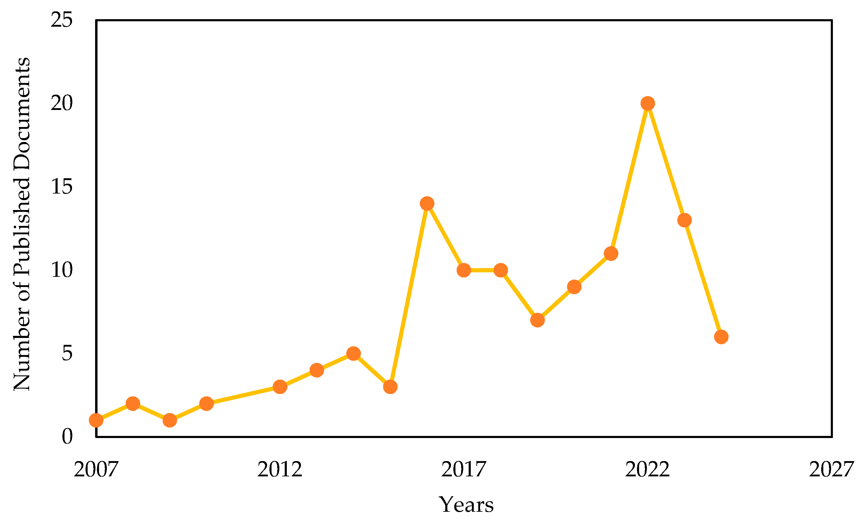
Figure 1. Number of publications on geothermal energy piles performance and design over time (access date 3 April 2024).
Energies 17 03386 g001
Figure 2. Keywords maps identified as most relevant to the research using VOS viewer software (version 1.6.20) [23].
Energies 17 03386 g002
Figure 3. The total number of geothermal energy piles worldwide corresponds to the total carbon dioxide savings worldwide resulting from all geothermal energy infrastructure projects (adapted from [36]).
Energies 17 03386 g003
Figure 4. Cross-section sketch of the heat transfer system embedded in the energy pile (adapted from [43]).
Energies 17 03386 g004
Figure 5. Schematic of ground heat exchanger system during summers and winters (adapted from [44]).
Energies 17 03386 g005
Figure 6. Flow chart for the estimation of thermal efficiency in an energy pile system (adapted from [50]).
Energies 17 03386 g006
Figure 7. Relationship between ground depth (covered by the driven energy pile) and thermal-induced stress obtained experimentally (adapted from [63]).
Energies 17 03386 g007
Figure 8. Heat exchanger tube configurations (adapted from [75]).
Energies 17 03386 g008
Figure 9. The influence of tube configuration on the annual thermal production of the energy piles system (adapted from [81]).
Energies 17 03386 g009
Figure 10. The influence of tube configuration on the cross-sectional temperature distribution of the energy piles system at depth of 12 m (adapted from [5]).
Energies 17 03386 g010
Table 1. Recent studies on energy piles.
AuthorPipe ConfigurationPile SizeMethod and/or SoftwareIncluded ExperimentalMain Result
Kong et al. [5]U-, W-, and 4U-shaped pipesDia = 0.6 m
Length = 24 m
COMSOL (version 4.4)YesThrough experiments and numerical models, it is revealed that while longer pipes can enhance thermal exchange, they also introduce substantial mechanical effects requiring consideration in design. Additionally, the research examines soil effects, demonstrating that soil thermal expansion mitigates thermal compressive stress over time and that higher soil elastic modulus increases thermal stress in energy piles.
(Kumar and Samui [72])U shaped pipeDia = 0.7 m
Length = 8 m
Machine learning algorithmsNoThe research identifies key variables for calculating energy pile capacity and employs soft computing algorithms like random forest, support vector machine, gradient boosting machine, and extreme gradient boosting to predict pile group capacity. The gradient boosting machine (GBM) technique demonstrates the best performance, with evaluation metrics indicating its accuracy in estimating energy pile group capacity compared to other models.
(Zhao et al. [73])-Dia = 1 m
Length = 44 m
FEMNoUnder intermittent operation, energy pile temperatures and surrounding ground exhibit periodic variation, with prolonged use leading to thermal accumulation and peak temperatures during the initial daily cycle. Temperature fluctuations induce axial compression or tensile stress, especially in summer/winter conditions, and partial energy pile usage causes additional tensile stress in nonenergy anchor piles.
(Faizal et al.) [74]-Dia = 0.025 m
Length = 0.264 m
-YesThe ratio of heating and cooling would have a significant impact on the hydraulic response when the temperature changes.
(Wu et al. [64]) Spiral-shaped pipePile full scaleCOMSOLUnderground solar energy storage (USES) testIncreasing the tube length is more sufficient for improving the performance of thermal injection comparing to changing the tube shape.
(Xiong et al. [65]-Dia = 1 m
Length = 44 m
-YesA slight change in radial effective contact pressure was noticed at the clay–pile interface during the heating process; however, a 55.3 kPa effective change in pressure was noticed at the sand–pile interface.
Disclaimer/Publisher’s Note: The statements, opinions and data contained in all publications are solely those of the individual author(s) and contributor(s) and not of MDPI and/or the editor(s). MDPI and/or the editor(s) disclaim responsibility for any injury to people or property resulting from any ideas, methods, instructions or products referred to in the content.