Article

Comprehensive Comparison of Different Rotor Structures of Low-Speed Permanent Magnet Motor

1
School of Electrical and Control Engineering, Xi’an University of Science and Technology, Xi’an 710054, China
2
Naval Research Institute, Beijing 100161, China
*
Author to whom correspondence should be addressed.
Energies 2024, 17(13), 3300; https://doi.org/10.3390/en17133300
Submission received: 26 April 2024 / Revised: 11 June 2024 / Accepted: 14 June 2024 / Published: 5 July 2024

Abstract

:
At present, most of the existing research on low-speed permanent magnet motors (LSPMMs) focuses on the surface-mounted type. There are few other rotor structures, and there is no comprehensive comparison of several widely used rotor structures. A comprehensive comparison of three different rotor structures for low-speed mining motors is carried out, including electromagnetic and loss characteristics, permanent magnet consumption, temperature distribution, etc. Firstly, three rotor structures of a 500 kW, 60 rpm low-speed motor are introduced, and the initial design parameters are determined. Secondly, the influence of each rotor design parameter on the electromagnetic characteristics is analyzed. Next, the electromagnetic optimization of the three rotor structures is carried out, and the motor performance of the three rotor structure optimization schemes is compared, including electromagnetic performance, permanent magnet consumption, motor temperature distribution, etc. Finally, in order to verify the correctness of the theoretical analysis, a prototype is made and tested based on the above analysis. The results show that for the electromagnetic characteristics, when the motors with three different rotor structures meet the performance requirements, the no-load line back-EMF of the inset surface-mounted motor is the lowest, but the back-EMF harmonic content of the inset surface-mounted motor is the highest. The copper loss of the spoke-type motor is the smallest, the efficiency is the highest, and the power factor is the lowest. In addition, the surface-mounted motor has the least consumption of permanent magnets and is more economical. Regarding the temperature distribution, when the same heat dissipation system is used, the temperature of the spoke-type motor with minimum copper loss is the lowest.

1. Introduction

Compared with asynchronous induction motors, low-speed and high-torque direct-drive permanent magnet synchronous motors have the advantages of large torque, high efficiency, low vibration noise, and green energy saving. Thanks to this, low-speed and high-torque transmission systems have extremely wide application prospects in industrial production, oilfield exploitation, wind power generation, port lifting, and ship propulsion [1]. However, for low-speed high-torque permanent magnet direct-drive motors, the number of poles and slots is usually large, the rated frequency is sometimes low, and the distortion of the air gap magnetic field is serious. In addition, for low-speed motors, the output harmonic component from the frequency conversion controller increases at low frequency. At the same time, different pole–slot combinations greatly affect the harmonic content of the air gap magnetic field of the motors, thus affecting the cogging torque of the motor. Therefore, selecting the appropriate slot–pole matching scheme is a major problem in the design process of low-speed high-torque direct-drive motors. Even if the ratio of the ripple to the rated torque is small, the actual torque ripple amplitude is large because the output torque is large when the speed is low [2]. On the one hand, it affects the control accuracy of the direct drive transmission system. On the other hand, a large torque ripple may cause rigid fatigue of the motor shaft, air gap eccentricity, and other faults, shortening the service life of the transmission system [3,4]. Therefore, a key problem in the design and optimization of low-speed high-torque direct-drive motors is selecting a suitable scheme to weaken the pulsating torque of low-speed high-torque direct-drive motors [5].
In response to the above problems, some researchers have proposed a variety of measures. On the one hand, the rotor structure, magnetic pole design parameters, pole slot matching, and algorithm are optimized. In Reference [6], the surface-mounted permanent magnet magnetic field modulation motor is taken as the research object, and the structural parameters are optimized to achieve a higher power factor. In Reference [7], a new three-vector model predictive flux control method for SPMSM with low computational complexity and a low stator flux ripple is proposed, thus improving the steady-state performance of the stator flux while reducing the computational complexity. In Reference [8], a new type of electric excitation claw pole field modulation motor is proposed, thus improving the utilization rate of effective harmonics and further improving the torque. The research in Reference [9] shows that the pole–slot matching method with high fundamental frequency can effectively weaken the cogging torque and reduce the torque ripple of a permanent magnet motor by selecting the appropriate pole–slot number while ensuring the other functions of the motor. Reference [10] optimizes the distribution of air gap flux density and permeance of a surface-mounted permanent magnet rotor by making the air gap of the motor uneven similar to unequal thickness and unequal width permanent magnets. On the other hand, starting from the design of the motor body, some parameters or structures are optimized to optimize electromagnetic performance. In Reference [11], a novel stator-shell matching method is proposed, which can improve the electromagnetic performance, thermal performance and stress deformation performance of permanent magnet synchronous motor. References [12,13,14] weaken the cogging torque to reduce the torque ripple by tilting the stator cogging to a stator pitch. The research in References [15,16,17,18] shows that the high local magnetic saturation caused by the asymmetric slot on the outer surface of the stator can significantly increase the cogging torque. References [19,20,21] take the V-type permanent magnet synchronous motor as the research object and show that a reasonable choice of slot width can effectively weaken the cogging torque of the V-type internal permanent magnet motor.
At the same time, through scientific optimization design and accurate parameter adjustment, many key indicators such as motor torque density, efficiency, noise, and cost can be significantly improved to meet changing market demand and complex operating environments [22]. Reference [23] innovatively combines fuzzy theory with the Taguchi method and successfully combines complex multi-objectives. The optimization problem is transformed into a single objective problem, which simplifies the optimization process. Reference [24] proposes a novel method combining pattern search and the genetic algorithm to search for the optimal parameter combination of a motor in the design space. Reference [25] uses a radial basis function neural network to construct a surrogate model and successfully establishes the mapping relationship between design variables and target performance. On this basis, combined with a multi-objective genetic algorithm for optimization, the torque performance of the motor is effectively improved. In order to capture the complex between variables and optimization objectives more accurately, in Reference [26], a variety of proxy models are constructed for detailed analysis and comparison. From the above analysis, it can be seen that the electromagnetic optimization of low-speed permanent magnet motors has been studied by many scholars. From the current equipment manufacturing cost point of view, the low-speed high-torque permanent magnet synchronous motor has a large volume and high cost under high-power demand. The optimization of the rotor structure is relatively limited. Therefore, it is meaningful to compare the optimization of various rotor structures.
However, most of the existing research on low-speed permanent magnet motors (LSPMM) focuses on the surface-mounted type, and there are few studies on other rotor structures. In addition, there is little comprehensive comparison of several widely used rotor structures. This makes it difficult for motor designers to choose low-speed motors with both good performance and economy. Therefore, this paper selects the three most common rotor structures as research objects. The three rotor structures are comprehensively compared in terms of magnetic and loss characteristics, permanent magnet consumption, temperature distribution, etc.
Firstly, in the first section, three rotor structures are introduced, and their initial design parameters are determined. Then, in the second section, by establishing a two-dimensional finite element model, the influence of different pole–slot combinations on electromagnetic performance is analyzed, and the pole–slot combinations of three rotor structures are determined. In the third section, the single-factor influence of rotor parameters on electromagnetic performance in different rotor structures is analyzed. Next, in the fourth section, the electromagnetic and permanent magnet consumptions of the three rotor structures are optimized, the response surface between the rotor design parameters and the motor performance is established, and the optimal design parameters of the three rotor structures are summarized. Then, in the fifth section, the three rotor structures are comprehensively compared, including electromagnetic and loss performance, permanent magnet consumption, temperature distribution, etc. In the sixth section, the theoretical analysis is verified by a prototype test. Finally, the seventh section summarizes the main conclusions of this paper.

2. LSPMM Structure and Main Performance

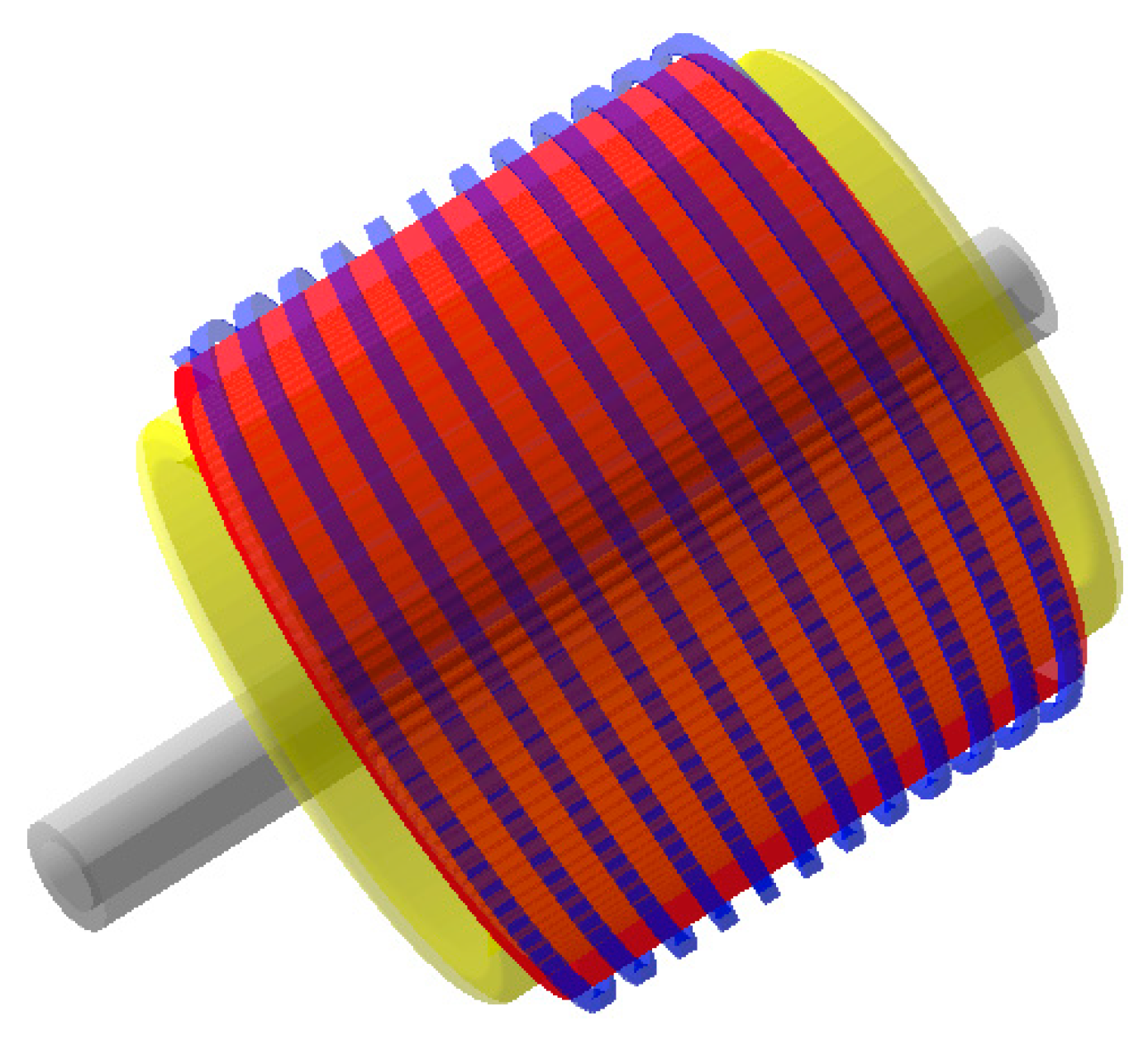
In this paper, a 500 kW, 60 rpm permanent magnet motor is taken as the research object, as shown in Figure 1. The main design parameters of the permanent magnet motor are shown in Table 1. In the analysis conducted in this paper, different rotor structures have the same stator design parameters.
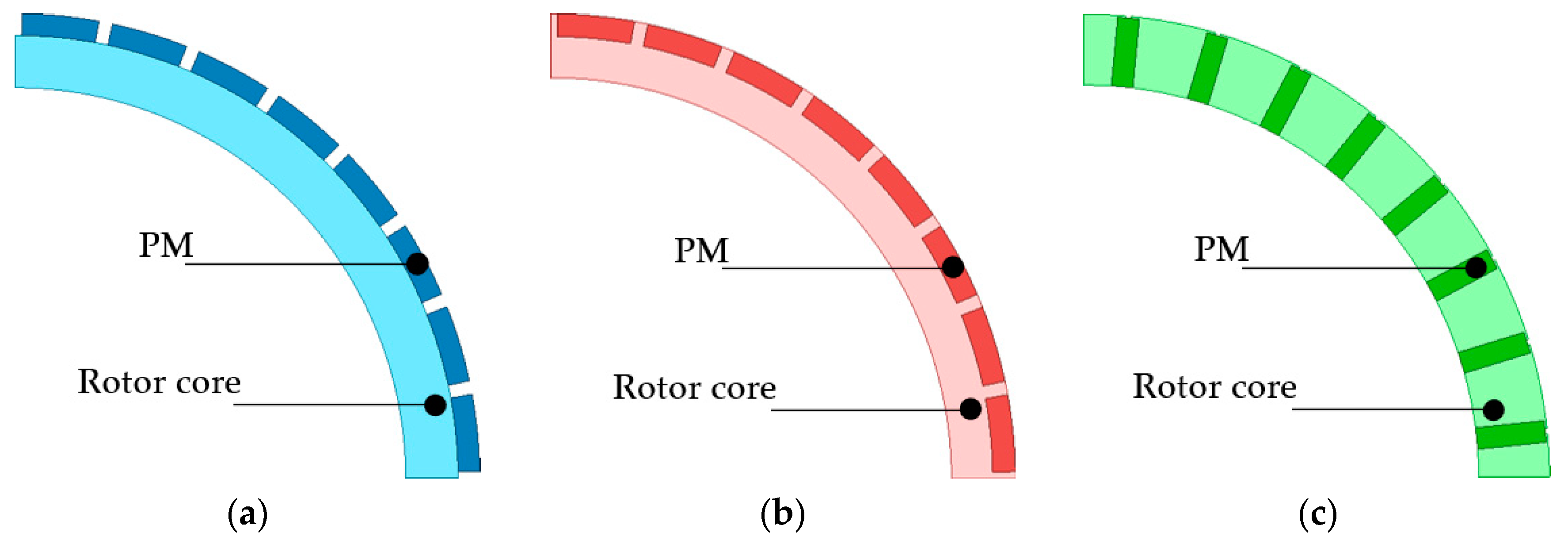
In the design process of a low-speed high-torque permanent magnet motor, in order to meet the high-power mining machinery, its volume is relatively large, and the price of permanent magnet materials is generally high, which causes the problem of high motor cost. In order to design a rotor with excellent electromagnetic characteristics and good economy, three different rotor structures are introduced, as shown in Figure 2, which are surface-mounted, inset surface-mounted, and spoke-type rotor structures.
For the surface-type rotor structure, the permanent magnet is attached to the outer side of the circular core of the rotor. Because the permeability of the permanent magnet material is close to the air gap permeability, the effective air gap length is the sum of the thickness of the air gap and the radial permanent magnet. The surface-mounted permanent magnet motor is a typical non-salient pole motor, without the salient pole effect and reluctance torque. The equivalent air gap of the quadrature and direct axis magnetic circuits of this kind of motor is very large, so the armature reaction is relatively small, the flux weakening ability is poor, and the constant power flux weakening operation range is usually small. As the permanent magnet is directly exposed to the air gap magnetic field, it is easy to demagnetize, and the flux weakening ability is limited. The surface-type rotor is especially suitable for square wave permanent magnet motors because of its simple manufacturing process and low cost.
In the interior permanent magnet motor, as the name implies, the permanent magnet is buried inside the rotor core. There is a pole shoe protection of the ferromagnetic material between the surface and the air gap, and the permanent magnet is protected by the pole shoe. For the built-in permanent magnet motor, the inductance of the q-axis is greater than the inductance of the d-axis, which is beneficial to the weak magnetic acceleration. Because the permanent magnet is buried inside the rotor core, the rotor structure is more solid, which easily improves the safety of the high-speed rotation of the motor. The inset surface-mounted rotor structure has a small magnetic flux leakage coefficient, the motor shaft does not need to take magnetic isolation measures such as magnetic isolation sleeves and magnetic bridges, the mechanical strength of the rotor punching sheet is large, and the rotor is not easily deformed. The permanent magnet is placed in the permanent magnet slot along the axial direction of the motor, and the magnetic flux leakage is suppressed by the pole interval magnetic bridge. For the spoke-type rotor magnetic circuit structure, two adjacent magnetic poles are in parallel to provide a magnetic flux at a pole distance. Therefore, a larger flux per pole can be obtained, which improves the utilization rate of permanent magnet materials and can save some permanent magnet materials. When the number of pole pairs of the motor is large, the advantage of the structure is more prominent.

3. The Influence of Rotor Design Parameters on Electromagnetic Performance

The rotor design of a low-speed permanent magnet motor is an important part of motor design. On the one hand, the air gap flux density and the utilization rate of the permanent magnet should be considered. On the other hand, the difficulty of magnetic pole assembly should also be considered. Therefore, it is necessary to study the different installation methods for permanent magnets. This section analyzes the influence of various design parameters on the electromagnetic characteristics of three rotor structures by establishing a two-dimensional finite element model.
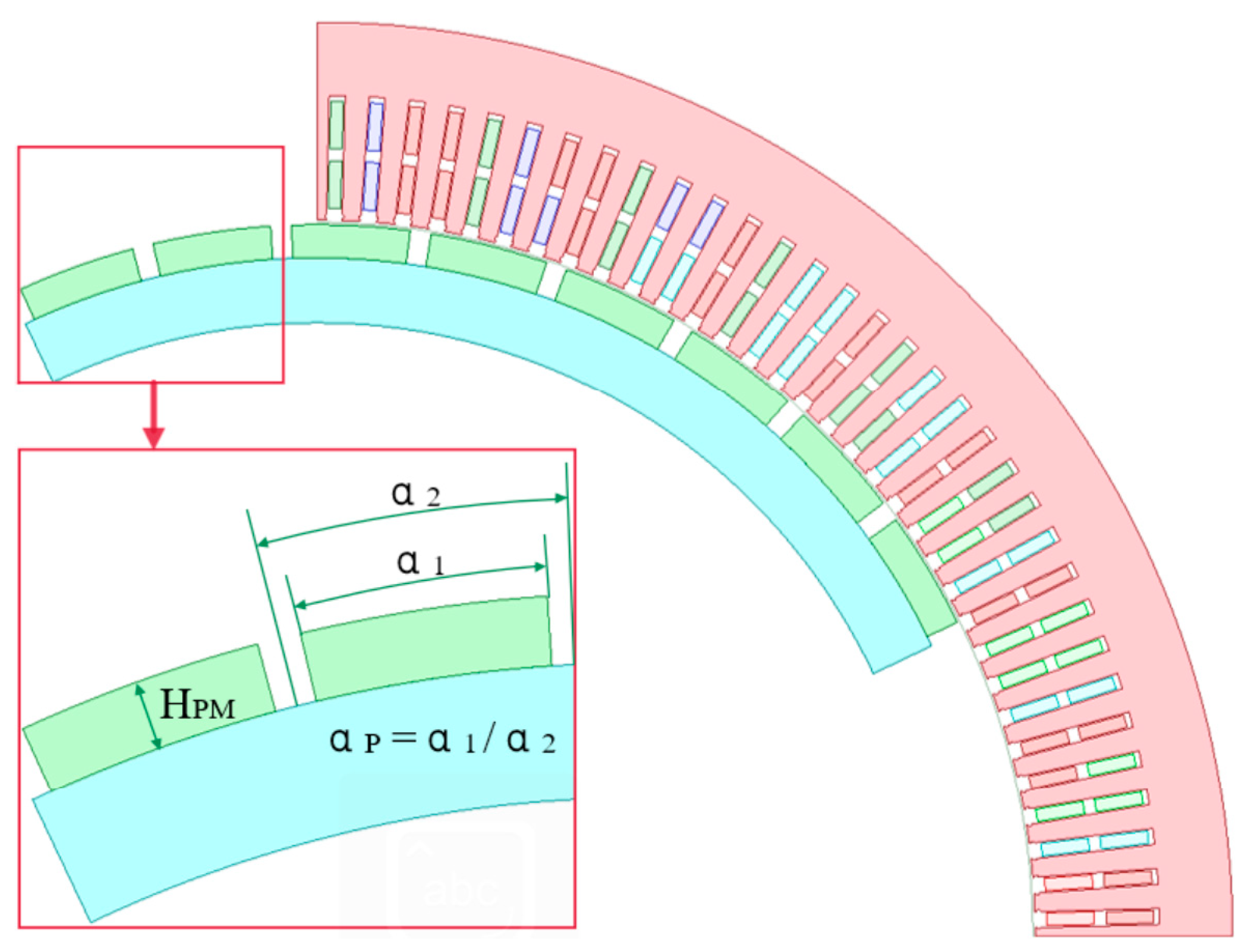
At present, the design of low-speed high-torque permanent magnet motors mostly adopts a surface-mounted rotor structure, and the surface-mounted rotor structure is shown in Figure 3. The main rotor design parameters are the permanent magnet pole arc coefficient (αP) and permanent magnet thickness (HPM).
In Reference [27], the influence of surface mounted rotor parameters on electromagnetic performance is studied in detail. This section focuses on the influence of inset sur-face-mounted and spoke-type rotor parameters on electromagnetic performance.

3.1. Influence of Inset Surface-Mounted Rotor Parameters on Electromagnetic Performance

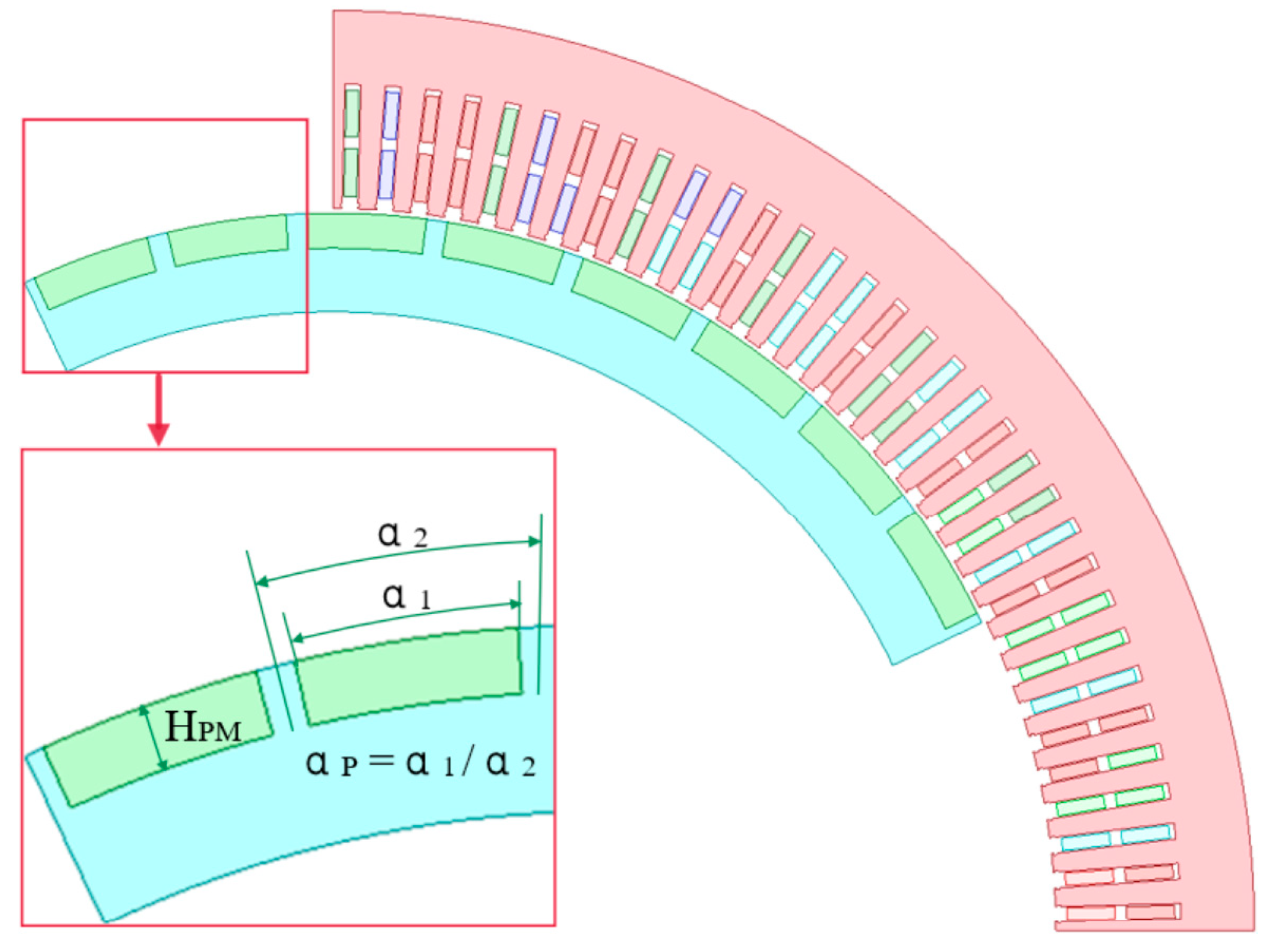
The inset surface-mounted rotor structure and the main parameters involved in this paper are shown in Figure 4. Rotated from the main design parameters are the permanent magnet pole arc coefficient (αP) and the permanent magnet thickness (HPM).
For the inset surface-mounted rotor structure, a single-factor influence analysis of the electromagnetic performance of the permanent magnet pole arc coefficient and the permanent magnet thickness as variables is also carried out, and the influence trend is shown in Figure 5. Figure 5a,b show the magnetic density distribution cloud diagram when the polar arc coefficient is 0.7 and 0.85. Figure 5c,d show the magnetic density of the air gap and the no-load anti-electromagnetic force under different pole arc coefficients. The observation in Figure 5d shows that the air gap flux density of the motor increases gradually with the increase in the pole arc coefficient. In addition, Figure 5c shows that the no-load back-EMF increases from 580 V to 650 V with the increase in the air gap flux density. The stator core loss decreases with the increase in the pole arc coefficient, as shown in Figure 5e, from 5.944 kW to 5.722 kW, which is reduced by about 222 W. At the same time, the copper consumption of the motor gradually decreased from 30.86 kW to 27.5 kW, by about 3.36 kW. As shown in Figure 5f, the motor efficiency gradually increases from 92.99% to 93.64%. At the same time, the power factor of the motor increases from 0.92 to 0.966.
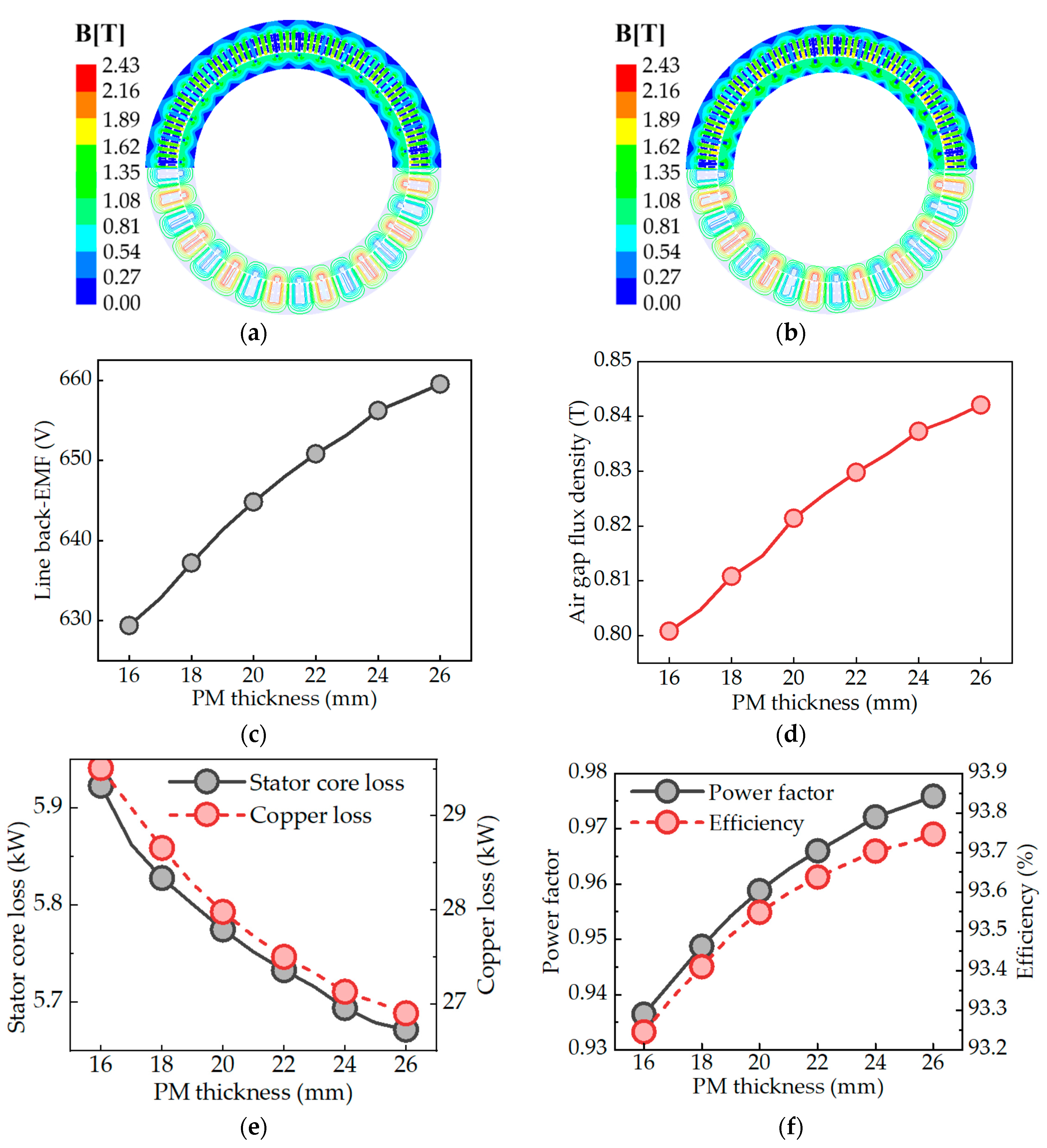
The electromagnetic characteristics are analyzed by changing the thickness of the permanent magnet from 16 mm to 26 mm. The single-factor influence trend of the permanent magnet thickness on the electromagnetic performance is shown in Figure 6. The magnetic density distribution of the permanent magnet with a thickness of 16 mm and 26 mm is shown in Figure 6a,b. Figure 6c,d illustrate the flux density in the air gap and the no-load back-EMF when the thickness of the permanent magnet increases from 15 mm to 25 mm, respectively. Specifically, the magnetic density in the air gap increases from 0.8 T to 0.84 T, and the no-load back-EMF increases from 629 V to 660 V, representing an increase of 31 V. Figure 6e shows the stator core loss and copper loss under different permanent magnet thicknesses. With the increase in the volume of the permanent magnet in the motor, the stator core loss decreases gradually from 5.923 kW to 5.672 kW, which is a reduction of about 300 W. At the same time, the copper consumption is reduced from 29.51 kW to 26.9 kW. Figure 6f shows the variation trend in the power factor and efficiency when the thickness of the permanent magnet increases from 15 mm to 25 mm. The power factor and efficiency increase, and the efficiency increases from 93.25% to 93.75%. In addition, the power factor increases from 0.936 to 0.976.

3.2. Influence of Spoke-Type Rotor Parameters on Electromagnetic Performance

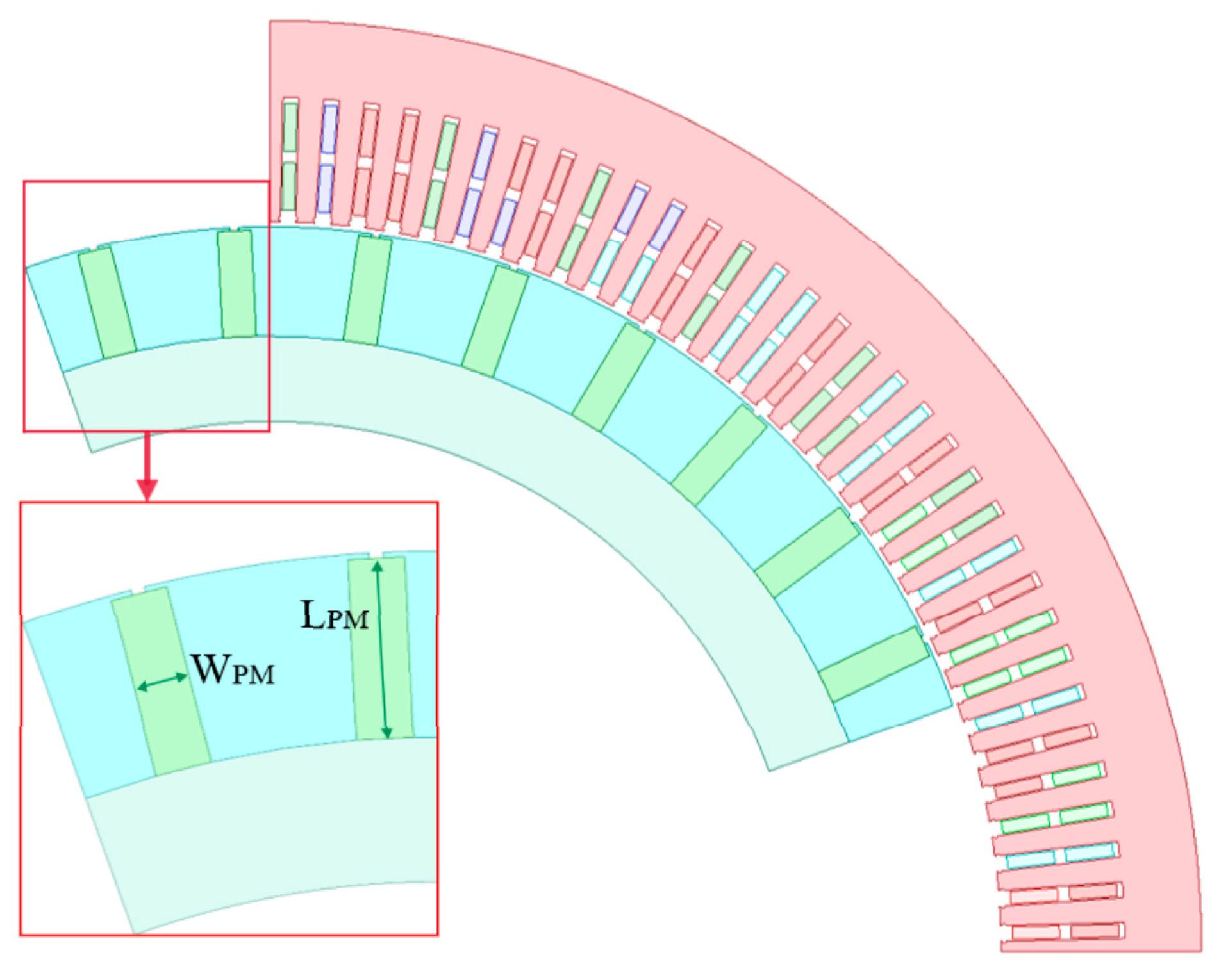
The spoke-type rotor structure and the main parameters involved in this paper are shown in Figure 7. The main design parameters are the length of the permanent magnet (LPM) and the width of the permanent magnet (WPM).
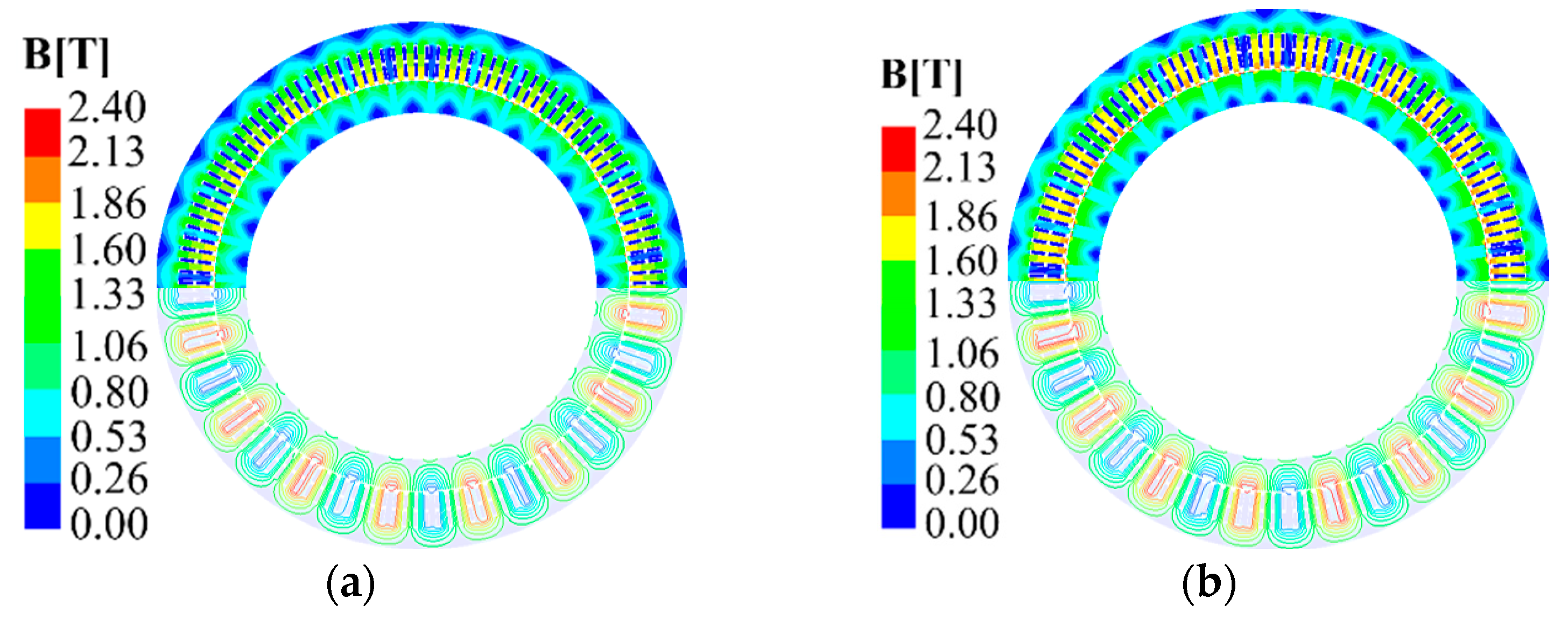
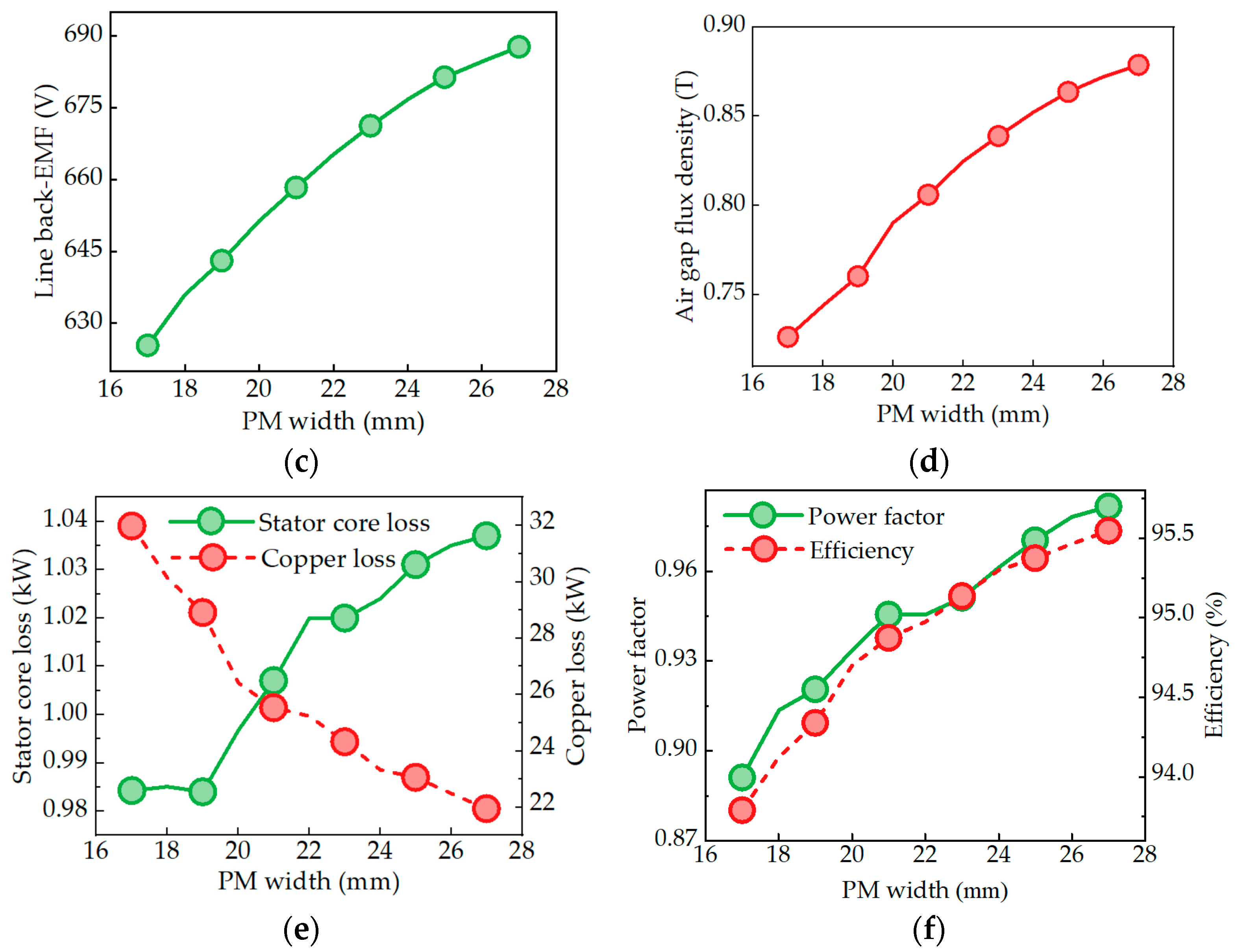
For the spoke-type rotor structure, a single-factor influence analysis of the electromagnetic performance is carried out with the permanent magnet pole arc coefficient and the permanent magnet thickness as variables, and the influence trend is shown in Figure 8. Figure 8a,b show the magnetic density distribution cloud map of the permanent magnet width of 17 mm and 27 mm. Figure 8c,d show the magnetic density of the air gap and the no-load anti-electromagnetic force under different permanent magnet widths. As shown in Figure 8d, as the width of the permanent magnet increases, the air gap flux density of the motor gradually increases. In addition, Figure 8c shows that the no-load back-EMF increases from 625 V to 687 V with the increase in the air gap flux density. The stator core loss increases with the increase in the width of the permanent magnet, as shown in Figure 8e, from 0.984 kW to 1.037 kW, representing an increase of about 53 W. On the contrary, the copper consumption of the motor gradually decreases from 31.98 kW to 21.95 kW, by about 10.03 kW. As shown in Figure 8f, the motor efficiency gradually increases from 93.79% to 95.55%. At the same time, the power factor of the motor increases from 0.89 to 0.98.
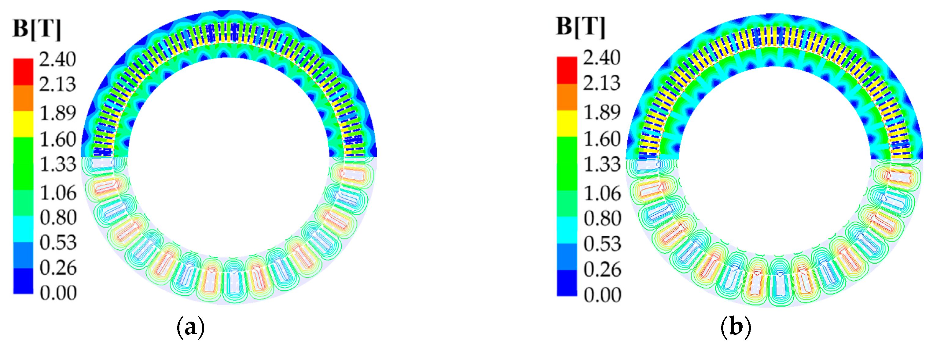
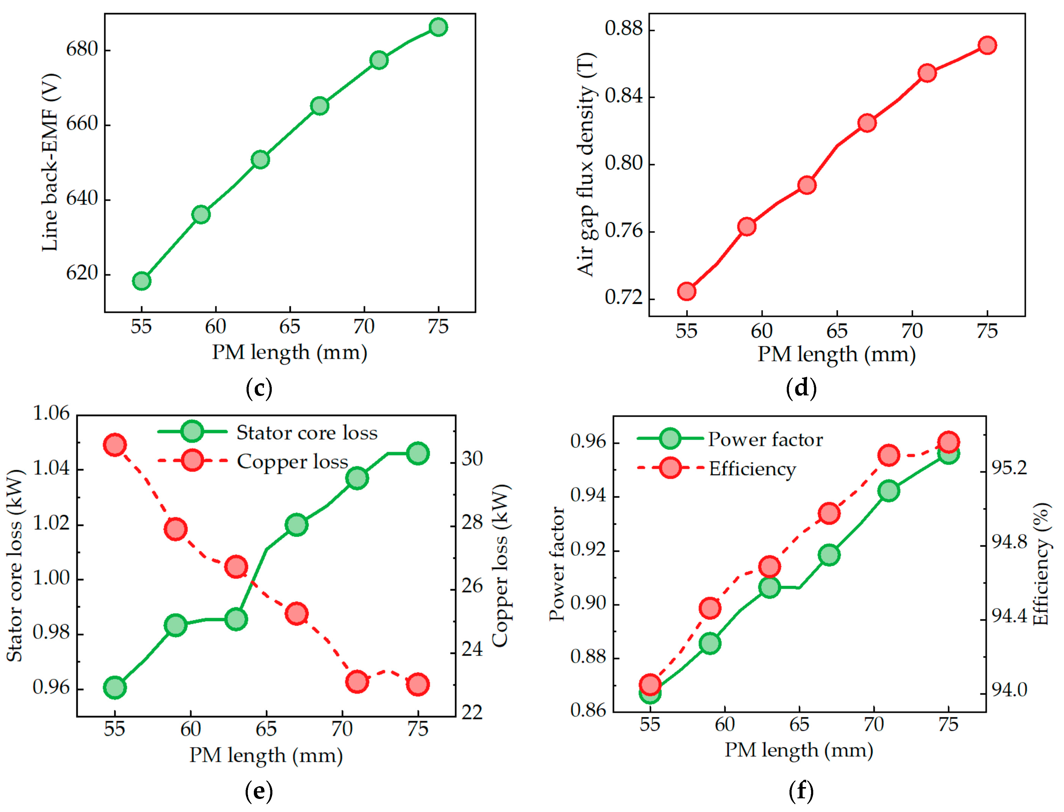
The electromagnetic characteristics are analyzed by changing the length of the permanent magnet from 55 mm to 75 mm. The single factor influence trend of the magnet length on the electromagnetic performance is shown in Figure 9. The magnetic density distribution of the permanent magnet with a length of 55 mm and 75 mm is shown in Figure 9a,b. Figure 9c,d illustrate the flux density in the air gap and the no-load back-EMF when the length of the permanent magnet increases from 55 mm to 75 mm, respectively. Specifically, the flux density in the air gap increases from 0.72 T to 0.87 T, while the no-load back-EMF increases by 68 V. Figure 9e shows the variation trend in stator core loss and copper loss with the change in the permanent magnet length. With the increase in the length of the permanent magnet in the motor, the loss of the stator core increases gradually from 0.96 kW to 1.046 kW, representing an increase of about 86 W. On the contrary, the copper consumption reduces from 30.56 kW to 23.01 kW. Figure 9f shows the trend in the power factor and efficiency when the length of the permanent magnet increases from 55 mm to 75 mm. The power factor and efficiency increase, and the efficiency increases from 94.0% to 95.36%. In addition, the power factor increases from 0.867 to 0.956.

4. Multi-Objective Optimization of Different Rotor Structures

Combined with the analysis results of the influence of rotor parameters on the performance of the motor in Section 3 and Section 4, and based on the initial design scheme of the four rotor structures in Section 4, this section carries out electromagnetic optimization considering the consumption of permanent magnets. Firstly, according to the optimization methods in the existing literature, the process and mathematical model of electromagnetic optimization are sorted out. Then, the optimization variables and optimization ranges of the three rotor structures are determined. Finally, through the establishment of the Kriging surrogate mode, the multi-objective genetic algorithm is used to find the optimal non-inferior solution, and the optimization scheme of the three rotor structures is determined.
For the surface-mounted rotor structure, the permanent magnet thickness, pole arc coefficient, and core length are selected as optimization variables. For the inset surface-mounted rotor structure, the permanent magnet thickness, pole arc coefficient, and core length are selected as optimization variables. For the spoke-type rotor structure, the length of the permanent magnet, the width of the permanent magnet, and the length of the core are selected as the optimization variables. Table 2 shows the optimization range of the three rotor structure design parameters.

4.1. Response Surface Analysis

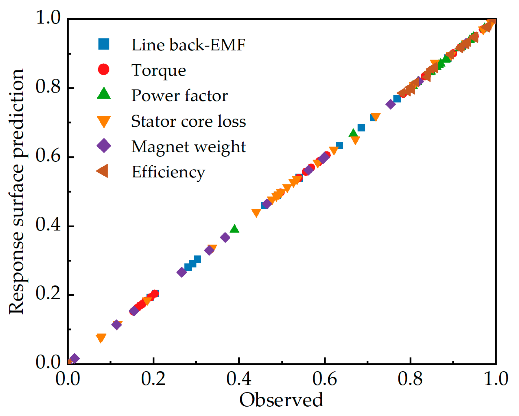
Firstly, a central composite design sampling design is used to obtain a uniform original sample. The electromagnetic analysis of the low-speed permanent magnet motors with different rotor structures is carried out for all sample data. A response surface surrogate model of rotor design parameters and motor performance is established by using the FEA results of the sample data. The Kriging surrogate model predicts the uncalculated data based on the calculated test sample data. It is an unbiased estimation model of experimental point results. Figure 10 summarizes the results of the two-dimensional finite element calculation and the response surface surrogate model. The response surfaces of the three rotor structures are shown in Figure 11, Figure 12 and Figure 13.
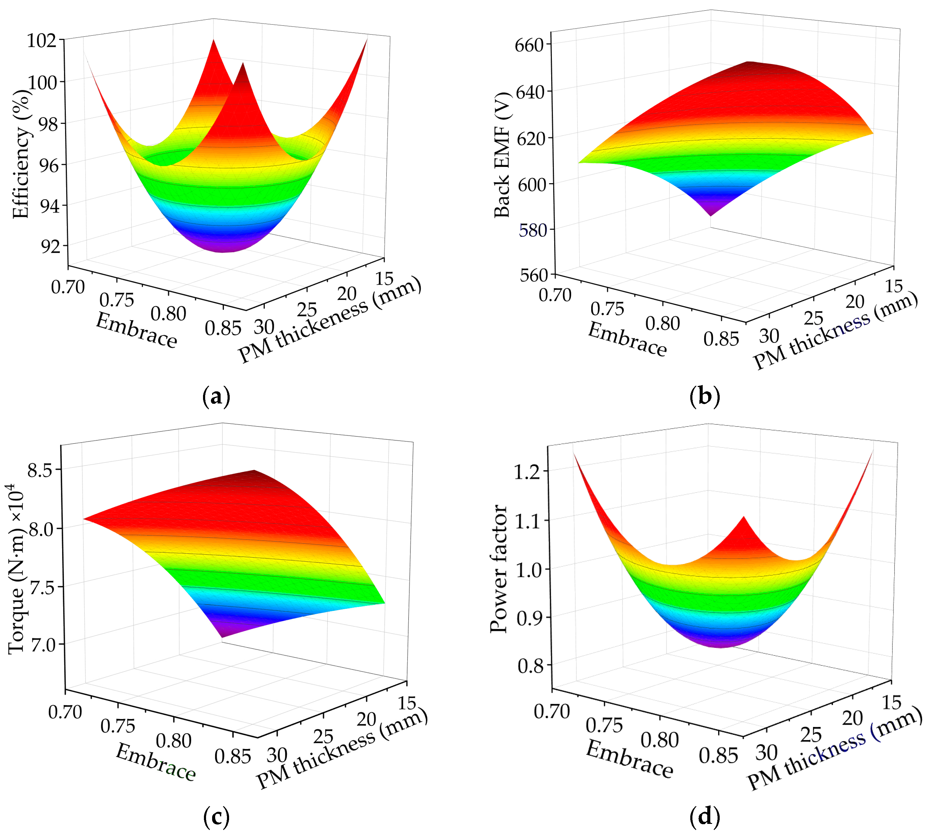
The response surface of the surface-mounted rotor design parameters to the motor performance is shown in Figure 11. With the increase in the pole arc coefficient and permanent magnet thickness, the efficiency of the motor decreases first and then increases. In Figure 11b, it can be seen that the thickness of the permanent magnet has a significant effect on the back electromotive force of the no-load line, and the influence of the pole arc coefficient is not significant. In addition, a higher amount of the permanent magnet means a higher torque. With the increase in the amount of the permanent magnet, the power factor decreases first and then increases.
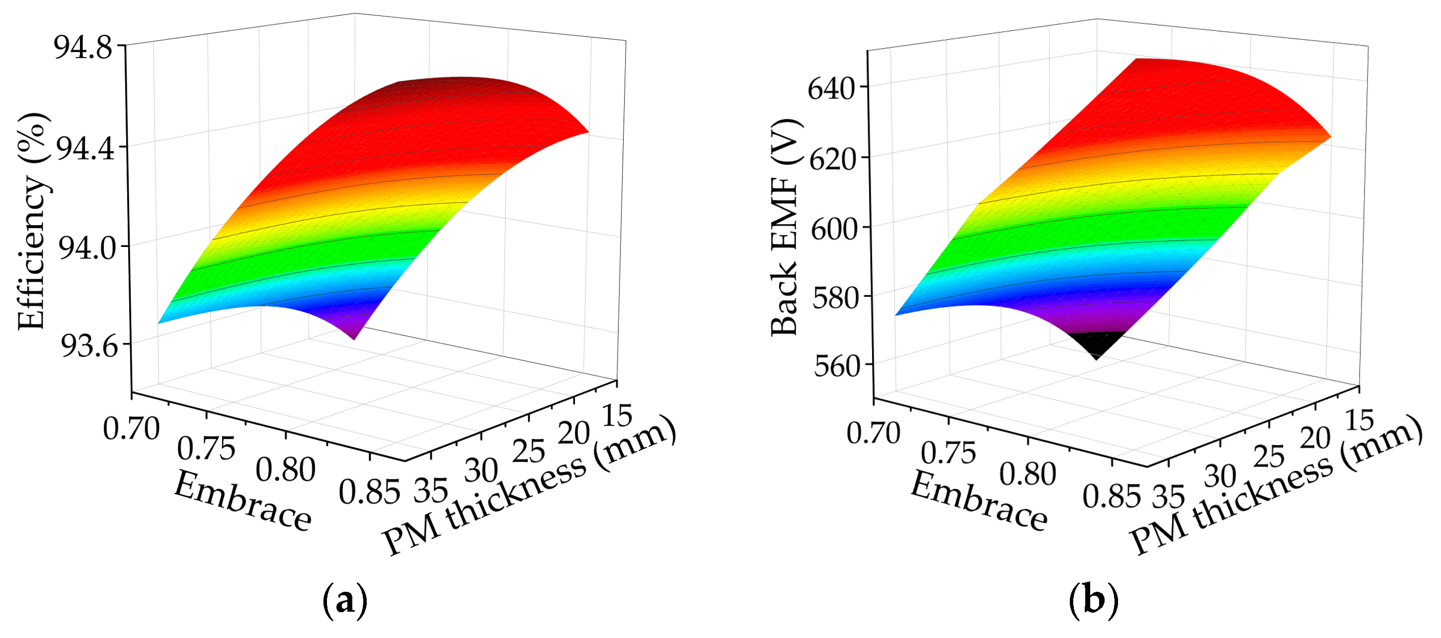
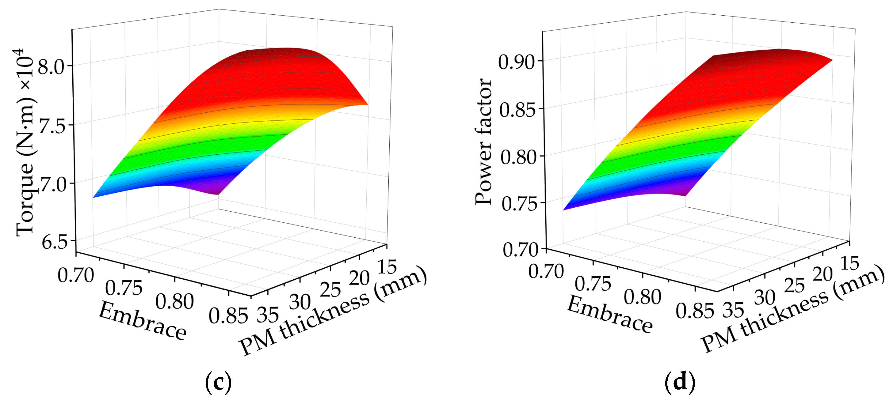
Figure 12 shows the influence of the design parameters of the inset surface-mounted rotor on the performance of the motor. The efficiency and no-load back-EMF of the motor increase significantly with the increase in the pole arc coefficient. Similar to the surface-mounted rotor, the torque of the motor increases with the increase in the amount of the permanent magnet. The influence of the pole arc coefficient of the permanent magnet on the power factor is obvious, and the thickness of the permanent magnet has little effect on the power factor compared with the pole arc coefficient.
The influence of the design parameters of the spoke-type rotor on the electromagnetic characteristics is shown in Figure 13. The no-load back-electromotive force and torque of the motor increase with the increase in the amount of the permanent magnet. When the thickness of the permanent magnet increases, the efficiency and power factor increase slightly. The width of the permanent magnet has a great influence on the electromagnetic performance. With the increase in the width of the permanent magnet, the efficiency and power factor increase significantly.

4.2. Sensitivity and Constraint Analysis

Sensitivity analysis is an effective method to evaluate the influence of a single parameter on an optimization objective. Before the electromagnetic optimization of the three rotor structure motors, a sensitivity analysis of the main optimization parameters is first carried out. The correlation coefficients of each optimization parameter for different optimization objectives are obtained. In this paper, the Pearson correlation coefficient is used to express the influence of each optimization parameter on different optimization objectives.
ρ X , Y = i = 1 n ( x i x ¯ ) ( y i y ¯ ) i = 1 n ( x i x ¯ ) 2 i = 1 n ( y i y ¯ ) 2
where y i is the value of the optimization objective corresponding to the optimization variable x i , and y ¯ is the average value of the optimization objective.
According to the above theoretical calculation, the finite element model is established and the sensitivity of the relevant structural parameters is calculated. Figure 14 shows the sensitivity coefficient of the optimization objects. The larger the value of the sensitivity coefficient, the greater the impact on the optimization goal. A positive value indicates that the optimization goal increases with the increase in the optimization variable, and a negative value is the opposite.
In this paper, in the process of the electromagnetic optimization of low-speed permanent magnet motors with three rotor structures, the maximum efficiency and the minimum permanent magnet volume are selected as the optimization objectives to obtain a more reasonable optimization scheme. The constraints of the optimization process of the low-speed permanent magnet motors include no-load line back-electromotive force, output torque, and power factor.
First, the no-load back-EMF of the low-speed permanent magnet motor should be slightly smaller than the rated voltage to ensure that there is sufficient excitation magnetic field to complete the electromechanical energy conversion process. Second, the torque is selected as the first constraint condition of the load operation, and the torque should be greater than the rated torque. In addition, the power factor is selected as the constraint condition. In order to obtain higher motor efficiency, the power factor is limited to 0.9 or more.
min : f 1 ( x ) = V
max : f 2 ( x ) = η
630   V E 650   V
7.96   N m T n
0.9 cos Φ
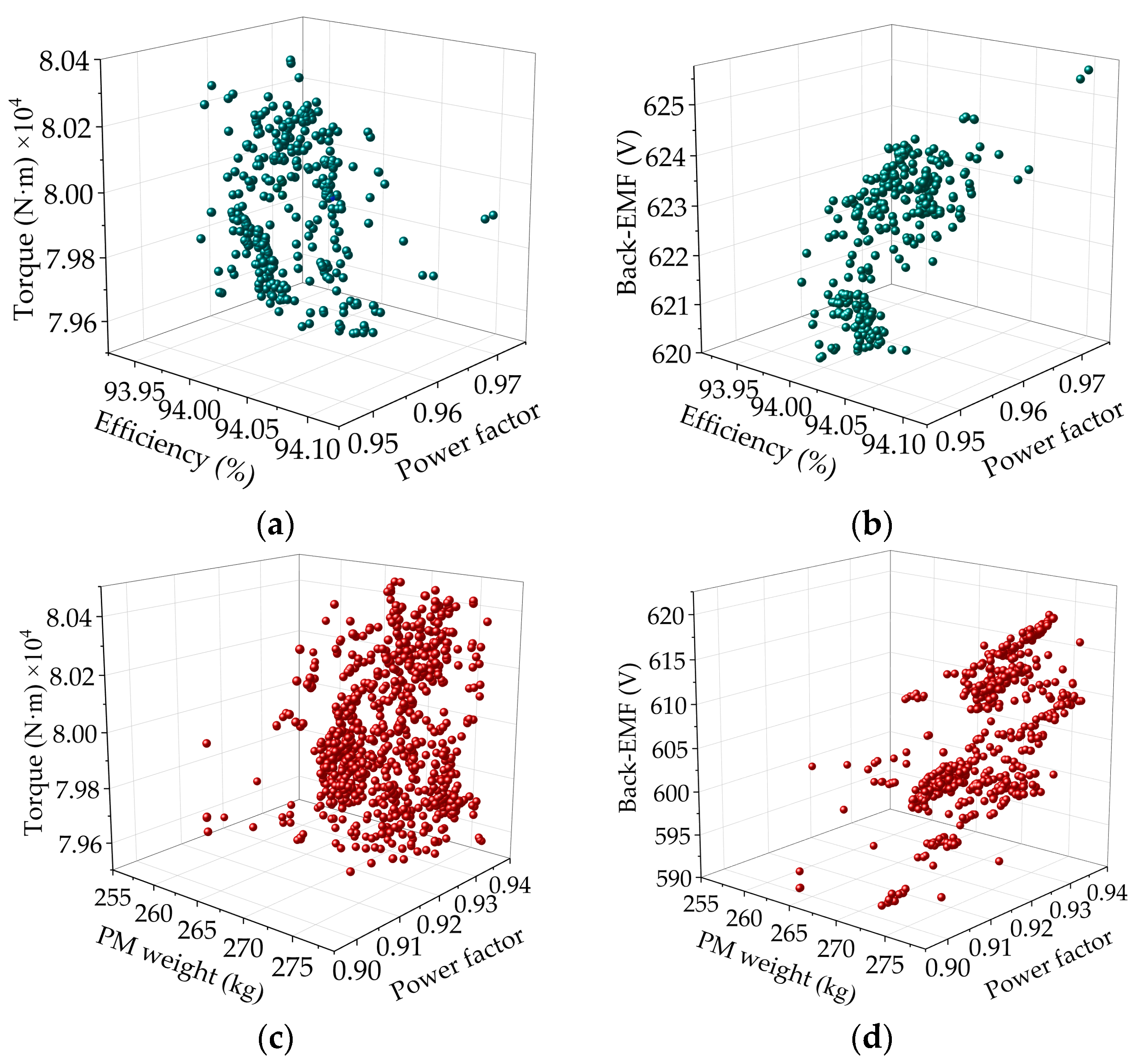
In the above formula, V is the volume of the permanent magnet, efficiency, E is the back-EMF of the no-load line, Tn is the output torque, and c o s Φ   is the power factor. In the electromagnetic optimization process of this paper, the multi-objective genetic algorithm method is used to optimize the Kriging surrogate model, and the Pareto front solution set is obtained. Taking the Pareto frontier diagram in Figure 15 of the surface-mounted rotor structure optimization as an example, based on satisfying the optimization constraints, all the solutions in the Pareto front are solutions that meet the optimization constraints. This requires that from the Pareto front, according to the design needs, a set of solutions that best meet the requirements is selected as the final optimization scheme. The optimization goal of this paper is the highest efficiency and the least consumption of permanent magnets. However, the optimization objectives cannot achieve the best results at the same time. The consumption of the permanent magnet used in the most efficient solution is not the least. Therefore, in the process of electromagnetic optimization, there is no set of optimal solutions, and all the performances of the motor achieve the best results. Instead, there is a compromise between all the optimization objectives. Finally, a compromise solution with the maximum efficiency and the minimum amount of permanent magnet is selected.

4.3. Optimal Results

For the three rotor structures, after completing the electromagnetic optimization taking into account the consumption of permanent magnets, the optimized rotor design parameters are obtained, as summarized in Table 3.

5. Comprehensive Comparison of Different Rotor Structures

Based on the above electromagnetic design optimization results, the design parameters of the three rotor structures selected have basically the same no-load back-EMF. This section makes a comprehensive comparison of the three rotor structures, including electromagnetic performance, permanent magnet consumption, and temperature distribution.

5.1. Comparison of the Electromagnetic Performance of Three Rotor Structures

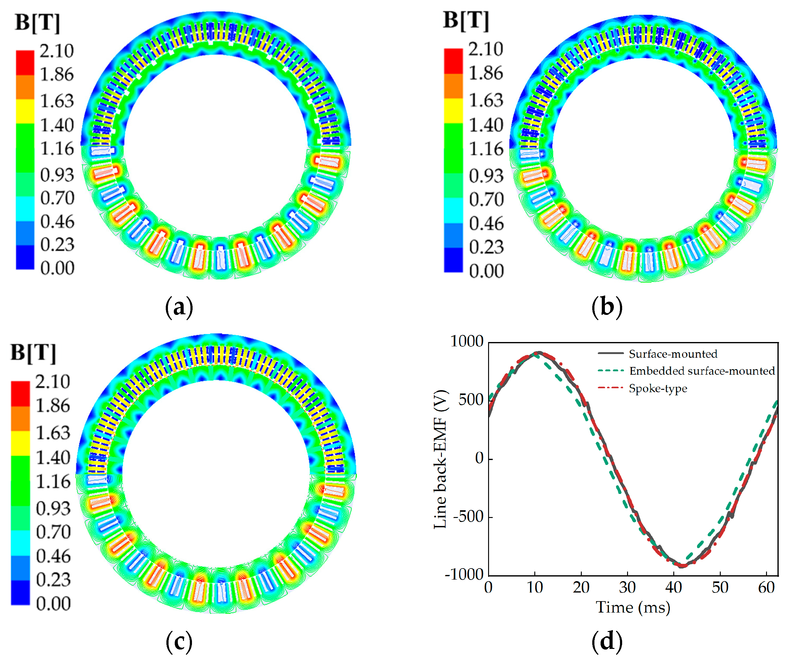
The magnetic density distribution cloud diagram and line back electromotive force of three kinds of rotor structure motors are obtained by the two-dimensional finite element method, as shown in Figure 16. The average no-load back-EMF of the three rotor structure motors is basically the same, which is maintained at about 620 V.
The Fourier transform results for the no-load back-EMF of the three rotor structure motors are shown in Figure 17. The back-EMF waveforms of the inset surface-mounted motors have higher fifth and seventh harmonics.
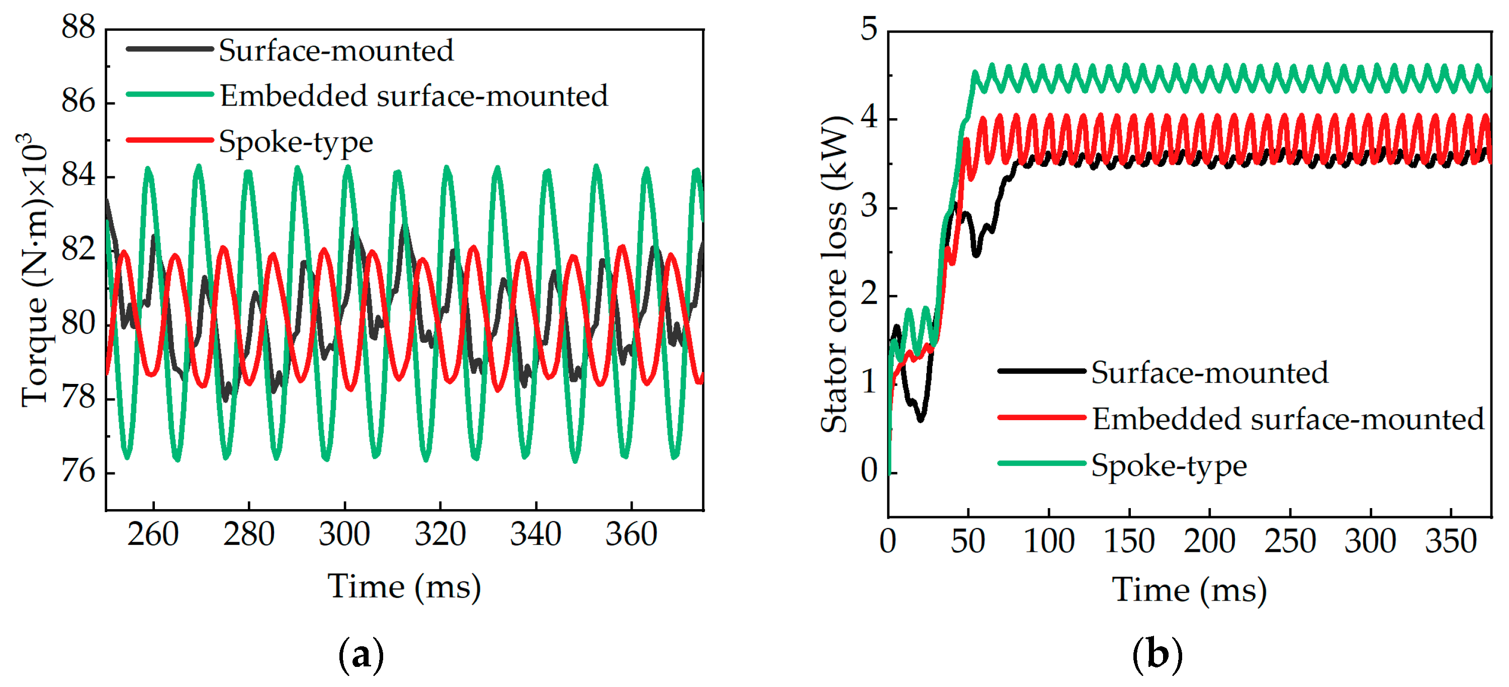
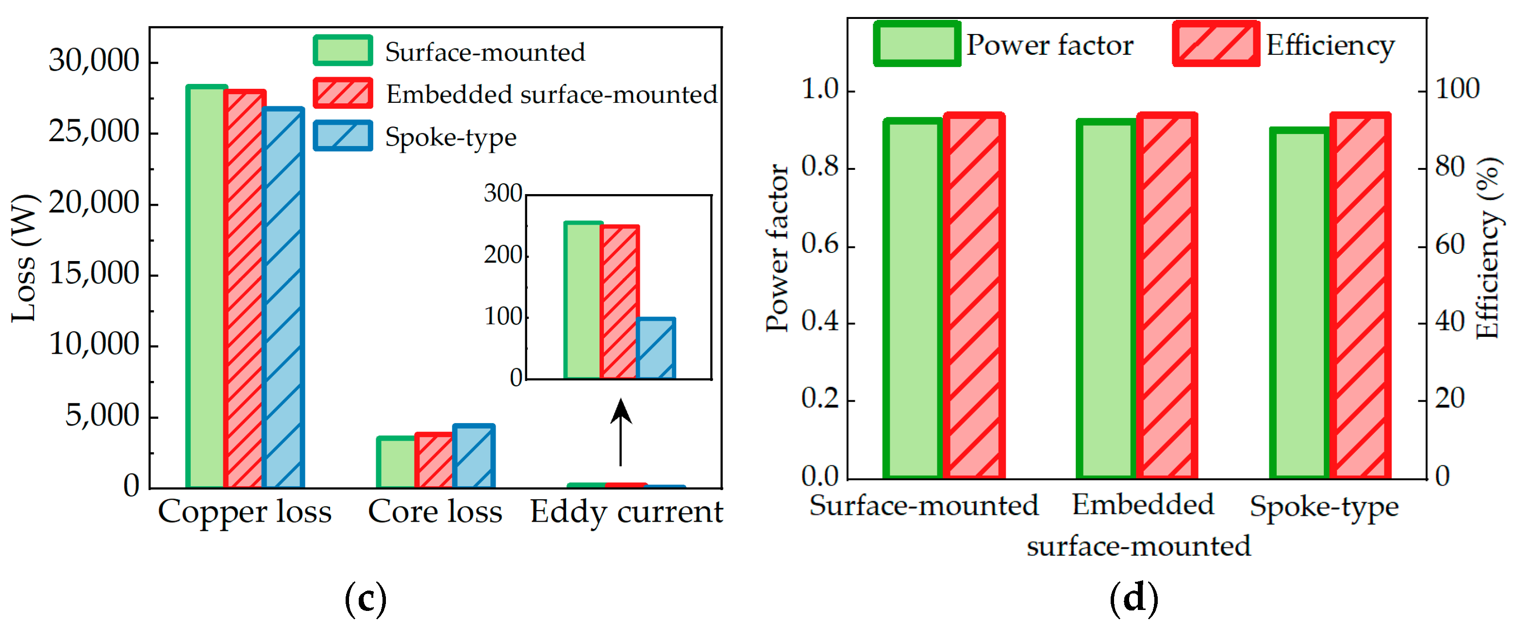
Figure 18 compares the load performance of the low-speed permanent magnet motors with three rotor structures. The rated torque is 79,584 N·m. In order to obtain the same output torque, the load current of the spoke-type is less than that of the surface-mounted-type and the inset surface-mounted-type. The inset surface-mounted torque ripple is the largest of the three rotor structures. In addition, the calculation results of the stator core loss of the three rotor structures are shown in Figure 18b. The stator core loss of the spoke-type type is significantly larger than that of the other two rotor structures.
The loss distribution of the three rotor structures is shown in Figure 18c. Compared with the other two motors, the load current of the spoke-type structure is smaller than that of the other two structures, and the copper loss of the spoke-type structure is the smallest, which is 5.8% and 4.6% smaller than that of the surface-mounted and inset surface-mounted rotor structures, respectively. The core loss of the spoke-type rotor is 887 W and 622 W higher than that of the surface-mounted rotor and the inset surface-mounted rotor. In addition, the spoke-type eddy current loss is also significantly lower than the other two rotor structures.
It is well known that there is a risk of irreversible demagnetization in NdFeB permanent magnet motors, which are used in this paper. The coercivity of the inflection point of the demagnetization curve of N42UH is about 1.1769 × 10⁶ A/m. Figure 19 shows the demagnetization of N42UH under 2 times the load. There is no irreversible demagnetization phenomenon in the surface-mounted rotor structure under 2 times load. However, the inset surface-mounted and spoke-type rotor structures have local irreversible demagnetization at the edge of the permanent magnet.
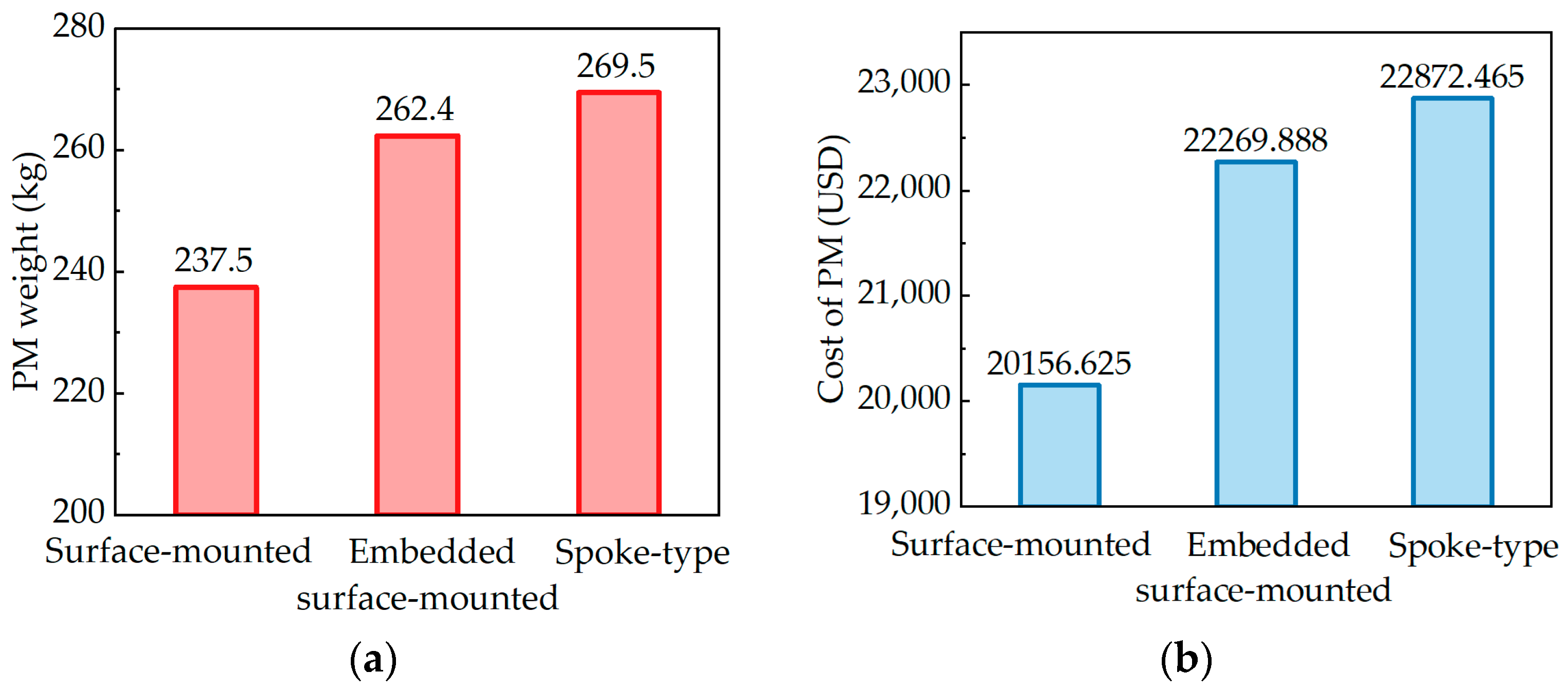
The amount and cost of permanent magnets of the three rotor structures are shown in Figure 20. The amount of the surface-mounted structure is 237.5 kg, and the inset surface-mounted and spoke-type structures are 262.4 kg and 269.5 kg. Obviously, the surface-mounted motor has the least weight of permanent magnets, which is 9.5% and 11.1% lower than the inset surface-mounted and spoke-type motors, and is thus more economical. Calculated at the price of 84.87 USD/kg of NdFeB, the cost of the surface-mounted permanent magnet is USD 20,156.625, as shown in Figure 20b. However, the cost of the inset surface-mounted permanent magnet is USD 22,269.888, and the cost of spoke-type permanent magnet is USD 22,872.465. Obviously, the surface-mounted rotor structure has the lowest cost.

5.2. Comparison of the Heat Transfer Characteristics of the Three Rotor Structures

In order to ensure the long-term safe operation and service life of low-speed permanent magnet motors, it is necessary to provide a good heat dissipation environment. At present, the commonly used motor cooling methods are air-cooling and water-cooling. According to the design requirements of the motor, in order to ensure that the motor can work safely, the water-cooling method is selected. The maximum temperature of the permanent magnet is limited to 120 °C. In this paper, the temperature distribution of the low-speed permanent magnet motor is simulated by using the thermal module in Motor-CAD. In order to compare the temperature distribution of motors with different rotor structures, the same cooling system is used to operate under rated conditions, that is, a power of 500 kW and a speed of 60 rpm.
In the thermal simulation calculation, the core loss, winding copper loss, and eddy current loss are set as the heat source, and the calculation is carried out according to the above load characteristics. As shown in Figure 21, the water-cooling system adopts a spiral water channel outside the stator. The water temperature and flow rate are set at 30 °C and 2.7 m3/h, respectively.
The temperature distribution of the low-speed permanent magnet motors with the three rotor structures is shown in Figure 22. The minimum temperature of the three rotor structures is concentrated on the rotor core. The highest temperature of the motor with the different rotor structures is located on the winding. The surface-mounted winding temperature is 112.6 °C, which is slightly higher than the inset surface-mounted winding temperature (108.2 °C). Among the three rotor structure motors, the spoke-type motor has the lowest overall temperature. Figure 22d compares the temperatures at different positions of the three rotor structures.
Table 4 details the comprehensive performance comparison of the three rotor structures, including electromagnetic performance, permanent magnet consumption, temperature distribution, etc. The maximum torque of the three rotor structures can characterize the overload capacity. It can be seen from the maximum torque in the table that the maximum torque of the surface-mounted motor is 131,950 N·m. The maximum torques of the inset surface-mounted and spoke-type motors are 126,590 N·m and 113,530 N·m. It can be seen that the overload capacity of the surface-mounted motor is the highest. The surface-mounted motor needs the least amount of the permanent magnet under the premise of ensuring the design performance requirements. Among the three rotor structures, the inset surface-mounted rotor structure has the smallest no-load back-EMF. The lowest total loss is in the spoke-type rotor structure. Overall, the spoke-type rotor structure has the highest efficiency, and the surface-mounted rotor structure has the highest power factor. In addition, the spoke-type temperature distribution is the lowest.

6. Prototype and Experimental Tests

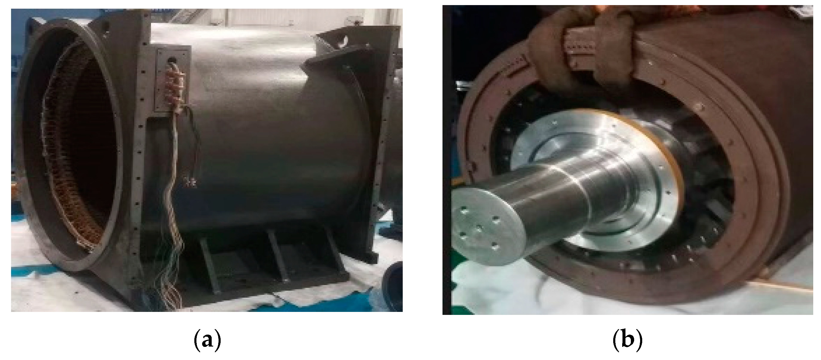
Based on the above analysis, the electromagnetic performance and temperature distribution of the surface-mounted rotor are the best of the three rotor structures. In order to verify the correctness of the theoretical analysis, a 500 kW, 60 rpm prototype is manufactured based on the surface-mounted rotor scheme, as shown in Figure 23a,b. In conditions where the prototype is under rated, its high torque presents challenges for evaluating its performance using conventional testing equipment. To assess the no-load and load performance of the prototype, specialized testing equipment designed for low-speed and high-torque permanent magnet motors is utilized. The experiment involves driving the prototype with a frequency converter, connecting it to a load motor via a belt, and linking the load motor to a hydraulic screw, which in turn is connected to a mechanical load. The figure illustrates the extensive size and complexity of the test system. Within this testing platform, the mechanical load can be adjusted to modify the torque of the load motor connected to it, which in turn transmits torque to the prototype via a belt for load adjustment. The power analyzer is connected at the power input end of the prototype to assess its electromagnetic performance.
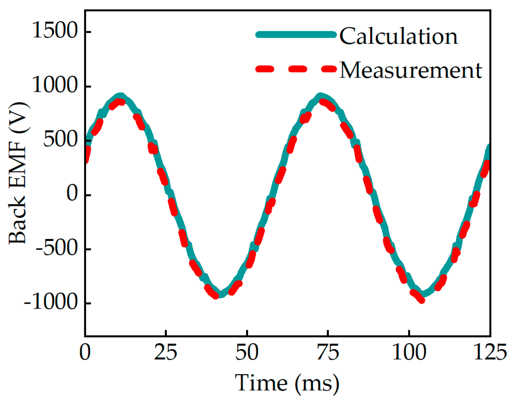
To determine the no-load back-EMF of the prototype, it is driven by a load motor operating at its rated speed. The no-load back-EMF of the prototype can be obtained by the power analyzer, as shown in Figure 24. As shown in Figure 24, the no-load back-EMF of the test is about 632 V, which is 8 V lower than the simulation value.
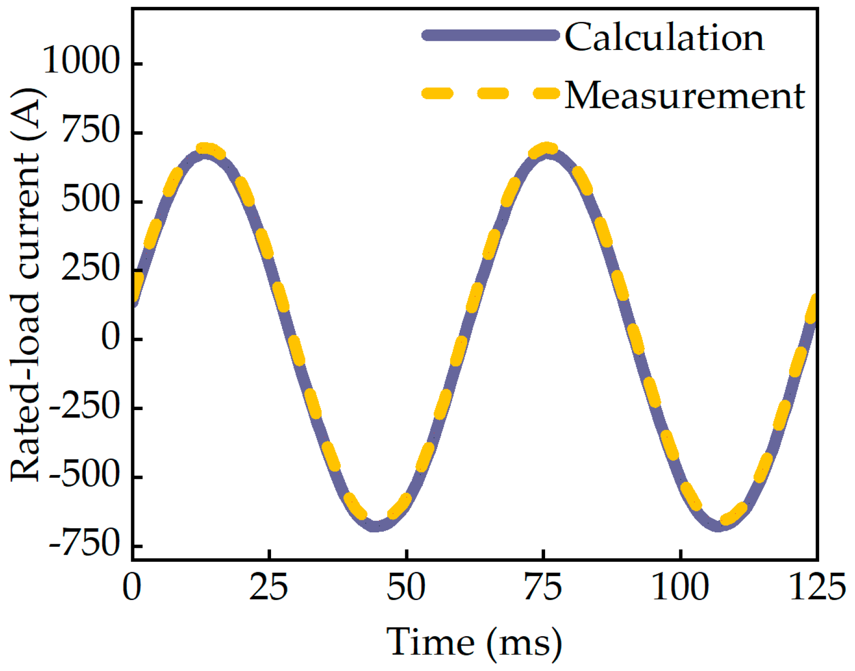
To determine the electromagnetic properties during rated operation, the prototype is powered by an inverter and operated under rated conditions by adjusting the mechanical load. The power supply voltage of the prototype is regulated to the rated voltage using a frequency converter. A high-range torque sensor is installed on the load motor side to measure the torque generated by the load motor. Consequently, the output power or torque of the prototype can be calculated based on the efficiency curve of the load motor. The power analyzer can be used to obtain the waveform of the prototype’s armature current at full load. As shown in Figure 25, the rated current of the prototype is about 486 A, which is 5 A higher than the calculated value. In addition, under the above cooling system, the measured winding temperature is about 115.3 °C after the motor runs for several hours in the rated state, which is slightly higher than the simulation result of 112.6 °C. The comparison between the measured and calculated performances is shown in Table 5.
The line-to-line back-EMF of the no-load operation is measured with the prototype driven by another motor. The measured peak-to-peak value of the line-to-line back-EMF at 30,000 rpm is 520 V, which is nearly the same as the designed voltage. The stator windings temperature at the rated load is measured by the Pt100 resistance temperature detectors installed in the stator slots. It can be found that the temperature of the measured windings is 60.9   ° C , which is close to the FEA calculation results of 56.7   ° C . Obviously, for the designed LSPMM, the measured value of electromagnetic performance and temperature characteristics are close to the calculated results, both satisfying the electromagnetic and thermal constraints.
In addition, the prototype worked at the rated speed for a long period. There was no damage to the rotor, which indicates that the design of the LSPMM is also reasonable, and the designed motor satisfies all of the multi-physics constraints in the real industry.
Overall, the experimental prototype tests validated that the designed motor meets all multi-physics constraints, including electromagnetic, mechanical, and thermal characteristics. This paper proposes, that the influence law of rotor length–diameter ratio on multi-physics is effective for the LSPMMs.

7. Conclusions

In this paper, a comprehensive comparison of three low-speed high-torque permanent magnet motors with different rotor structures is carried out, including electromagnetic and loss characteristics, permanent magnet consumption, temperature distribution, etc. Before the comprehensive comparison, the influence of rotor design parameters on electromagnetic characteristics is analyzed. Then, electromagnetic optimization considering consumption is carried out for three rotor structures. The three rotor structures adopt the same objectives and constraints in the optimization process. Finally, a prototype is made based on the surface-mounted rotor structure. The theoretical analysis is verified by a prototype test. Through the comprehensive comparative analysis of the three rotor structures, the following key conclusions are drawn:
  • For the electromagnetic characteristics, when the three structures meet the design performance requirements, the no-load line back-EMF of the inset surface-mounted rotor is the lowest, while the back-EMF harmonic content of the inset surface-mounted is the highest. The copper loss of the spoke-type rotor is the smallest, which is 5.8% and 4.6% smaller than that of the surface-mounted rotor and the inset surface-mounted rotor, respectively. The core loss is 887 W and 622 W higher than that of the surface-mounted rotor and the inset surface-mounted rotor, respectively. The efficiency of surface-mounted and inset surface-mounted is 93.96% and 93.67%m respectively. The spoke-type copper consumption is the lowest, and its efficiency is 94.11%, which increased. However, compared with the power factors of the surface-mounted and inset surface-mounted motors, which are 0.925 and 0.924, the power factor of the spoke-type motor is lower, which is 0.902.
  • The consumption of the permanent magnet for the surface-mounted structure is 237.5 kg, the inset surface-mounted is 262.4 kg, and the spoke-type is 269.5 kg. Obviously, the surface-mounted motor has the lowest consumption of permanent magnets, which is 9.5% and 11.1% lower than the inset surface-mounted and spoke-type motors, respectively; thus, the economy is better.
  • For the temperature distribution, the highest temperature of the three rotor structures is concentrated on the winding. When the same heat dissipation system is used, the spoke-type rotor structure has the lowest temperature because of the minimum loss.

Author Contributions

Conceptualization, G.D.; data curation, H.L. and G.D.; formal analysis, H.L.; funding acquisition, G.D.; investigation, H.L. and G.D.; methodology, H.L., G.D., R.J. and W.L.; project administration, G.D.; resources, G.D.; software, H.L., R.J. and W.L.; supervision, G.D.; validation, G.D., H.L., R.J. and W.L.; visualization, H.L.; writing—original draft, H.L.; writing—review and editing, H.L., G.D. and S.H. All authors have read and agreed to the published version of the manuscript.

Funding

This work was partly supported by the Key Research and Development Program of Shaanxi, 2024GX-YBXM-243.

Data Availability Statement

Data are contained within the article.

Conflicts of Interest

The authors declare no conflicts of interest.

References

  1. Du, G.; Hu, C.; Zhou, Q.; Gao, W.; Zhang, Q. Multi-Objective Optimization for Outer Rotor Low-Speed Permanent Magnet Motor. Appl. Sci. 2022, 12, 8113. [Google Scholar] [CrossRef]
  2. Xia, C.; Ji, B.; Yan, Y. Smooth speed control for low-speed high-torque permanent-magnet synchronous motor using proportional-integralresonant controller. IEEE Trans. Ind. Electron. 2014, 62, 2123–2134. [Google Scholar] [CrossRef]
  3. Sopanen, J.; Ruuskanen, V.; Nerg, J. Dynamic torque analysis of a wind turbine drive train including a direct-driven permanent-magnet generator. IEEE Trans. Ind. Electron. 2011, 58, 3859–3867. [Google Scholar] [CrossRef]
  4. Cistelecan, M.V.G.; Popescu, M.; Popescu, M. Study of the number of slots/pole combinations for low speed permanent magnet synchronous generators. In Proceedings of the IEEE International Electric Machines & Drives Conference, Antalya, Turkey, 3–5 May 2007; Volume 2, pp. 1616–1620. [Google Scholar]
  5. Hu, W. Research on Optimization Design of Low Speed High Torque Permanent Magnet Direct Drive Motor; Nanchang University: Nanchang, China, 2022. [Google Scholar]
  6. Li, X.; Wei, Z.; Zhao, Y.; Wang, X.; Hua, W. Design and analysis of surface-mounted permanent-magnet field-modulation machine for achieving high power factor. IEEE Trans. Ind. Electron. 2024, 71, 4375–4386. [Google Scholar] [CrossRef]
  7. Lu, K.; Li, X.; Zhao, Y.; Yi, P.; Yan, B.; Hua, W. A novel three-vector-based model predictive flux control with low computation complexity for SPMSM. IEEE Trans. Transp. Electrif. Early Access TTE 2023, 33, 5522. [Google Scholar] [CrossRef]
  8. Li, X.; Wang, X.; Dong, Y.; Lu, K.; Feng, X. Design and analysis of electric-excitation claw-pole field-modulated machine considering effective harmonics. IEEE Trans. Ind. Appl. Early Access TIA 2024, 33, 96. [Google Scholar] [CrossRef]
  9. El-Refaie, A.M.; Jahns, T.M.; Novotny, D.W. Analysis of surface permanent magnet machines with fractional-slot concentrated windings. IEEE Trans. Energy Convers. 2006, 21, 34–43. [Google Scholar] [CrossRef]
  10. Fang, S.; Xue, S.; Pan, Z.; Yang, H.; Lin, H. Torque Ripple Optimization of a Novel Cylindrical Arc Permanent Magnet Synchronous Motor Used in a Large Telescope. Energies 2019, 12, 362. [Google Scholar] [CrossRef]
  11. Li, L.N.; Zhu, G.J. Electromagnetic-Thermal-Stress Efforts of Stator-Casing Grease Buffers for Permanent Magnet Driving Motors. IEEE Trans. Ind. Electron. 2024, 60, 1268–1276. [Google Scholar] [CrossRef]
  12. Yang, Z.; Yang, M.; Wang, S. The influence of stator skewed slot on the performance of permanent magnet synchronous motor. J. Electr. Eng. 2019, 14, 97–102. [Google Scholar]
  13. Zhu, Z.Q.; Chen, J.T.; Wu, L.J.; Howe, D. Influence of Stator Asymmetry on CoggingTorque of Permanent Magnet Brushless Machines. IEEE Trans. Magn. 2008, 44, 3851–3854. [Google Scholar] [CrossRef]
  14. Sun, T.; Dai, Y.; Wang, Z. Analysis of the Generation andWeakening of Cogging Torque in Interior Permanent Magnet Machine. J. Phys. Conf. Ser. 2020, 1549, 1742–6596. [Google Scholar] [CrossRef]
  15. Gao, Y.; You, B.; Ruan, X.Z.; Liu, M.Y.; Yang, H.L.; Zhan, Q.F.; Li, Z.; Lei, N.; Zhao, W.S.; Pan, D.F.; et al. Depinning of domain walls in permalloy nanowires with asymmetric notches. Sci. Rep. 2016, 7, 32617. [Google Scholar] [CrossRef] [PubMed]
  16. Li, Y.; Bobba, D.; Sarlioglu, B. Design and optimization of a novel dual-rotor hybrid pm machine for traction application. IEEE Trans. Ind. Electron. 2018, 65, 1762–1771. [Google Scholar] [CrossRef]
  17. Xie, B.C.; Yue, Z.; Wang, J.Q. An efficient multidisciplinary design research for the integratedlow speed permanent magnet motor system based on analytical and numerical hybrid analysis. Energy Rep. 2022, 8, 199–208. [Google Scholar] [CrossRef]
  18. Zhang, G.; Tao, J.X.; Li, Y.F. Magnetic Equivalent Circuit and Optimization Method of aSynchronous Reluctance Motor with Concentrated Windings. Energies 2022, 15, 1735. [Google Scholar] [CrossRef]
  19. Bao, X.; Liu, J.; Sun, Y. Research Review and Prospect of Low Speed High Torque Permanent Magnet Direct Drive Motor. Trans. China Electrotech. Soc. 2019, 34, 1148–1160. [Google Scholar]
  20. Zhang, N. Research and Design of High Performance and Low Cost Belt Conveyor Permanent Magnet Motor for Mine; Shenyang University of Technology: Shenyang, China, 2021. [Google Scholar]
  21. Xv, C. Research on Pole-Slot Selection of Low-Speed High-Torque Permanent Magnet Direct-Drive Motor; Shenyang University of Technology: Shenyang, China, 2017. [Google Scholar]
  22. Lei, G.; Zhu, J.; Guo, Y.; Liu, C.; Ma, B. A Review of Design Optimization Methods for Electrical Machines. Energies 2017, 10, 1962. [Google Scholar] [CrossRef]
  23. Shi, Z.; Sun, X.; Cai, Y.; Yang, Z. Robust design optimization of a five-phase PM hub motor for fault-tolerant operation based on Taguchi method. IEEE Trans. Energy Convers. 2020, 35, 2036–2044. [Google Scholar] [CrossRef]
  24. Lok, C.L.; Vengadaesvaran, B.; Ramesh, S. Implementation of hybrid pattern search–genetic algorithm into optimizing axial-flux permanent magnet coreless generator (AFPMG). Electr. Eng. 2017, 99, 751–761. [Google Scholar] [CrossRef]
  25. Hao, J.; Suo, S.; Yang, Y.; Wang, Y.; Wang, W.; Chen, X. Optimization of Torque Ripples in an Interior Permanent Magnet Synchronous Motor Based on the Orthogonal Experimental Method and MIGA and RBF Neural Networks. IEEE Access 2020, 8, 27202–27209. [Google Scholar] [CrossRef]
  26. Pan, Z.; Fang, S. Combined Random Forest and NSGA-II for Optimal Design of Permanent Magnet Arc Motor. IEEE J. Emerg. Sel. Top. Power Electron. 2021, 99, 1800–1812. [Google Scholar] [CrossRef]
  27. Du, G.; Li, H.; Zhang, G.; Hu, C.; Zhang, Q.; Liang, L. Electromagnetic Design of Low Speed Inner Rotor Permanent Magnet Motor for Mine Direct Drive System. In Proceedings of the 2023 26th International Conference on Electrical Machines and Systems (ICEMS), Zhuhai, China, 5–8 November 2023; pp. 1149–1154. [Google Scholar]
Figure 1. Low-speed permanent magnet motor model.
Energies 17 03300 g001
Figure 2. Three rotor structures including (a) surface-mounted; (b) inset surface-mounted; and (c) spoke-type.
Energies 17 03300 g002
Figure 3. Design parameters of the surface-mounted rotor structure.
Energies 17 03300 g003
Figure 4. Design parameters of the inset surface-mounted rotor structure.
Energies 17 03300 g004
Figure 5. The effect of the embrace on electromagnetic properties: (a,b) magnetic flux density distribution; (c) line-to-line back-EMF; (d) air gap flux density; (e) stator core loss and copper loss; and (f) the power factor and efficiency.
Energies 17 03300 g005
Figure 6. The effect of the PM thickness on electromagnetic properties: (a,b) magnetic flux density distribution; (c) line-to-line back-EMF; (d) air gap flux density; (e) stator core loss and copper loss; and (f) the power factor and efficiency.
Energies 17 03300 g006
Figure 7. Design parameters of the spoke-type rotor structure.
Energies 17 03300 g007
Figure 8. The effect of the PM width on electromagnetic properties: (a,b) magnetic flux density distribution; (c) line-to-line back-EMF; (d) air gap flux density; (e) stator core loss and copper loss; and (f) the power factor and efficiency.
Energies 17 03300 g008aEnergies 17 03300 g008b
Figure 9. The effect of the PM length on electromagnetic properties: (a,b) magnetic flux density distribution; (c) line-to-line back-EMF; (d) air gap flux density; (e) stator core loss and copper loss; and (f) the power factor and efficiency.
Energies 17 03300 g009aEnergies 17 03300 g009b
Figure 10. The degree of fitting between the calculation results and the response surface prediction.
Energies 17 03300 g010
Figure 11. Response surface of surface-mounted rotor design parameters to motor performance: (a) efficiency; (b) line-to-line back-EMF; (c) torque; and (d) the power factor.
Energies 17 03300 g011
Figure 12. Response surface of inset surface-mounted rotor design parameters to motor performance: (a) efficiency; (b) line-to-line back-EMF; (c) torque; and (d) the power factor.
Energies 17 03300 g012aEnergies 17 03300 g012b
Figure 13. Response surface of spoke-type rotor design parameters to motor performance: (a) efficiency; (b) line-to-line back-EMF; (c) torque; and (d) the power factor.
Energies 17 03300 g013
Figure 14. The sensitivity of the optimized parameters of the three rotor structures: (a) surface-mounted; (b) inset surface-mounted; and (c) spoke-type.
Energies 17 03300 g014
Figure 15. Relationships among multi-objective performances: (a) relationship among efficiency, power factor, and torque; (b) relationship among efficiency, the power factor, and back-EMF; (c) relationship among the weight of the permanent magnet, the power factor, and torque; and (d) relationship among the weight of the permanent magnet, the power factor, and back-EMF.
Energies 17 03300 g015
Figure 16. The magnetic flux density distribution and no-load back-EMF of the three rotor structures: (ac) magnetic flux density distribution, (a) surface-mounted; (b) inset surface-mounted; (c) spoke-type; and (d) back-EMF.
Energies 17 03300 g016
Figure 17. No-load back-EMF harmonics of the three rotor structures.
Energies 17 03300 g017
Figure 18. The load electromagnetic characteristics of the three rotor structures: (a) torque; (b) stator core loss; (c) loss; and (d) the power factor and efficiency.
Energies 17 03300 g018aEnergies 17 03300 g018b
Figure 19. Demagnetization of NdFeB under 2 times the load: (a) surface-mounted; (b) inset surface-mounted; and (c) spoke-type.
Energies 17 03300 g019
Figure 20. Weight and cost of permanent magnet of three rotor structures: (a) weight and (b) cost.
Energies 17 03300 g020
Figure 21. Motor-cooling system design.
Energies 17 03300 g021
Figure 22. Temperature comparison of the three rotor structures: (a) surface-mounted; (b) inset surface-mounted; and (c) spoke-type and (d) a temperature comparison.
Energies 17 03300 g022
Figure 23. The surface-mounted rotor structure prototype: (a) stator and (b) rotor.
Energies 17 03300 g023
Figure 24. Comparison of calculated and measured no-load back-EMF waveforms at rated speed.
Energies 17 03300 g024
Figure 25. Comparison of calculated and measured rated-load current waveforms at rated speed.
Energies 17 03300 g025
Table 1. The main parameters of the designed motor for HSPMM.
ParametersValues
Output power500 kW
Rated rotating speed60 rpm
Rated load voltage690 V
Torque79,583 N·m
Stator outer diameter1160 mm
Air gap3 mm
Table 2. Rotor optimization parameters and range.
ParametersRange
Surface-MountedInset Surface-MountedSpoke-Type
Permanent magnet thickness (HPM)/mm[15, 30][15, 35]-
Polar arc coefficient (αp)[0.7, 0.85][0.7, 0.85]-
Length of permanent magnet (LPM)/mm--[55, 75]
Width of permanent magnet (WPM)/mm--[15, 30]
Core length (LS)/mm[800, 920][800, 920][800, 920]
Table 3. Parameters of the simulation model. (a) surface-mounted; (b) inset surface-mounted; and (c) spoke-type.
ParametersSurface-MountedInset Surface-MountedSpoke-Type
Polar arc coefficient0.750.76-
Permanent magnet thickness16.5 mm18.2 mm-
Width of permanent magnet--20.2 mm
Length of permanent magnet--61.5 mm
Core length908 mm901 mm903 mm
Table 4. Three rotor schemes of the LSPMM.
ParametersSurface-MountedInset Surface-MountedSpoke-Type
Polar arc coefficient0.750.76-
Permanent magnet thickness16.5 mm18.2 mm-
Width of permanent magnet--20.2 mm
Length of permanent magnet--61.5 mm
Core length908 mm901 mm903 mm
Weight of permanent magnet237.5 kg262.4 kg269.5 kg
Cost of PM20,157 USD22,270 USD22,872 USD
Back-EMF632 V609 V649 V
Torque80,142 N·m80,264 N·m80,130 N·m
Maximum torque131,950 N·m126,590 N·m113,530 N·m
Core loss3565 W3830 W4452 W
Copper loss28.33 kW28.00 kW26.76 kW
Magnet eddy current loss255 W249 W99 W
Efficiency93.96%93.97%94.11%
Power factor0.9250.9240.902
Stator winding temperature112.6 ° C 108.2 ° C 98.8 ° C
Table 5. Measured and calculated performances at rated load.
ParametersMeasurementCalculation
Power (kW)502500
Back-EMF (V)624632
Current (A)486481
Power factor0.910.92
Stator   winding   temperature   ( ° C )115.3113.2
Disclaimer/Publisher’s Note: The statements, opinions and data contained in all publications are solely those of the individual author(s) and contributor(s) and not of MDPI and/or the editor(s). MDPI and/or the editor(s) disclaim responsibility for any injury to people or property resulting from any ideas, methods, instructions or products referred to in the content.