Technical Note

Frequency Modulation Control of Grid-Forming Converter Based on LADRC-MI

1
School of Electric Power Engineering, South China University of Technology, Guangzhou 510640, China
2
Key Laboratory of Clean Energy Technology of Guangdong Province, Guangzhou 510640, China
3
Power Dispatch Control Center, Guangdong Power Grid Corporation, Guangzhou 510699, China
4
School of Electrical and Electronic Engineering, Tianjin University of Technology, Tianjin 300384, China
5
Tianjin Key Laboratory of New Energy Power Conversion, Transmission and Intelligent Control, Tianjin 300384, China
*
Author to whom correspondence should be addressed.
Energies 2024, 17(13), 3282; https://doi.org/10.3390/en17133282
Submission received: 29 May 2024 / Revised: 20 June 2024 / Accepted: 28 June 2024 / Published: 4 July 2024

Abstract

:
The increasing proportion of new energy in the power system leads to a decrease in system inertia and weakens the frequency stability of the system. The use of grid-forming (GFM) control for inverters is an effective method to improve frequency stability in new energy generation systems. Due to uncertain disturbances in microgrids, it can cause changes in system frequency. A control strategy for linear active disturbance rejection control combined with model information (LADRC-MI) is proposed in this manuscript. In this method, the inertia level and damping of the system are improved by using virtual synchronous generator (VSG)-based GFM control. Then, the obtained part of the model information is written into the coefficient matrix of the linear extended state observer. The LADRC-MI is constructed to improve the immunity of the controller. Finally, the effectiveness of the strategy in improving the immunity and frequency stability of the converter is analyzed and verified.

1. Introduction

In recent years, in order to achieve the “double carbon” strategic goal, new energy generation techniques, such as wind power and photovoltaic power, have developed rapidly [1,2]. The frequency stability of power systems with high proportions of new energy presents challenge. Wind and solar renewable energy power generation exhibit characteristics such as randomness, volatility, and strong intermittency. These characteristics makes the active power balance of the system more and more difficult. A power system with a high proportion of new energy exhibits a low inertia level, poor frequency regulation ability, and poor anti-interference ability. Due to the fact that power electronic devices in the power grid are usually controlled in grid-following mode, the grid lacks an inertia response and frequency regulation capability. This seriously affects the safe operation of the power system under the high proportion of new energy penetration [3,4].
To solve the above problems, the concept of grid-forming control (GFM) is put forward [5,6]. By simulating the external characteristics of synchro, the GFM converter exhibits the characteristics of the voltage source, and the goal of providing active support for the dynamic response of the system voltage and frequency is realized [7,8,9]. In reference [10], the existing GFM control methods are introduced. In reference [11,12], inertia and damping are introduced into the power control loop so that the generation system can simulate the synchronous generator to achieve primary frequency modulation and primary voltage regulation. In references [13,14,15], an integral compensator is proposed in parallel to eliminate the frequency deviation caused by load disturbance, and an integral link is adopted in the forward path to eliminate the steady-state power deviation. In reference [16], the virtual synchronous generator (VSG) control mode is proposed, which enables the VSG to achieve steady-state, constant power operation in a grid-connected state. At the same time, it can provide inertia support for the system in the dynamic process. In references [17,18,19], a VSG control method based on inertial adaptive is proposed, which summarizes the relationship between the output power and the frequency change rate of grid-connected inverters. The above research simulates the primary frequency modulation capability by simulating the inertia response of a synchronous generator, which can provide some support for frequency changes. However, the frequency support effect is limited due to the fact that final steady-state frequency modulation effect depends on the inertial response.
The variation in power grid frequency is caused by the imbalance of active power in the system. Therefore, the regulation of the power grid frequency is essentially the control of the active power disturbance of the system. The load change in the system, the switching of the generator, and the power fluctuation of the new electric energy field can be regarded as the active power disturbance in the system [20,21]. Linear active disturbance rejection control (LADRC) exhibits the advantages of simple structure, strong anti-interference ability, and good robustness [22]. LADRC utilizes a linear extended state observer (LESO) to estimate the disturbance information in real time. However, traditional LADRC relies on LESO to estimate all summation perturbations without considering the separation of the available prior information from summation perturbations. This increases the observation burden of LESO, resulting in slow response speed of the controller.
Aiming at the above problems, in order to quickly and accurately compensate for the power disturbance and adjust the frequency, this manuscript proposes the introduction of LADRC combined with model information (LADRC-MI) as the outer-loop frequency controller on the basis of GFM active power–frequency control. Then, the load power disturbance condition is simulated. The control results of traditional LADRC and LADRC-MI are compared, and the effectiveness of the inverter frequency modulation method based on LADRC-MI and GFM control is verified.

2. GFM Power Generation System Model

The research object of this manuscript is a three-level grid-connected inverter with grid control. Its system structure is shown in Figure 1, and the parameters of each power component in Figure 1 are shown in Table 1. It is mainly composed of a DC bus, three-level inverter, filter circuit, power grid, and AC load. The scenario considered in this research is that the DC power grid after voltage regulation in a wind power plant generates electricity to the receiving end of the low-inertia grid through the grid inverter. Because this research focuses on the regulation of the frequency of the grid, the DC side is simplified as an ideal DC voltage source. The receiving side is replaced by an equivalent generator to respond to the frequency change.
The parameters of each power component in Figure 1 are as follows:

3. GFM Control Model

3.1. GFM Controller Model

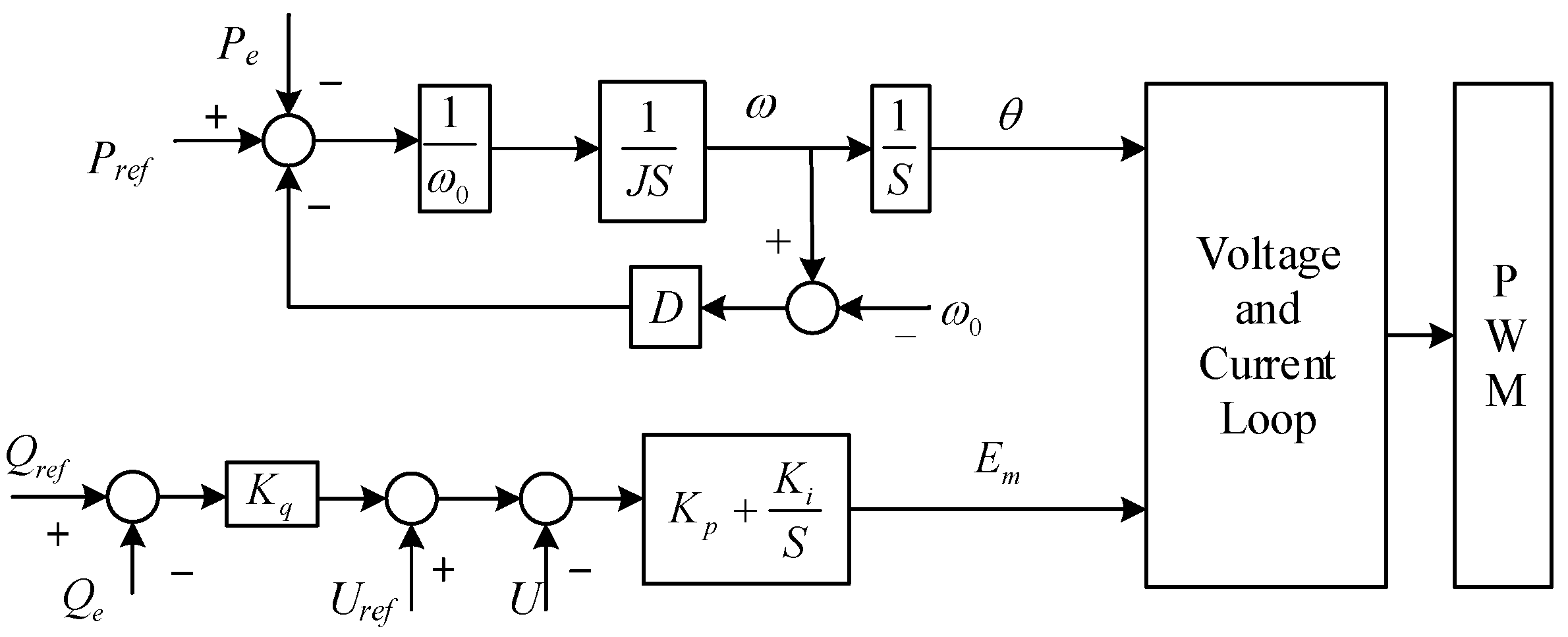
GFM control does not require a phase-locked loop to maintain synchronization with the phase of the power grid. GFM control independently constructs frequency and voltage by imitating synchronous machines [23]. The GFM controller model under the VSG control strategy is shown in Figure 2.
Because this research focuses on frequency control, it is assumed that the voltage and reactive power flow fluctuations of the receiving grid can be ignored. Therefore, the reactive power control component in the GFM controller is ignored in the modeling process.
{ ω ˙ = 1 J [ P r e f ω 0 P e ω 0 D ( ω ω 0 ) ] θ ˙ = ω
where Pref and Pe are the active power reference value and actual output power of the inverter. J and D are the virtual inertia and virtual damping coefficient, respectively. ω and ω0 are the generated angular frequency and rated angular frequency of the system. θ is the generated AC side voltage phase reference value.

3.2. Receiving Grid Equivalent Model

To make the receiving power grid respond to the frequency changes, an equivalent generator is used to simulate the power grid. The equivalent generator model consists of the governor model and the synchronous generator model, as shown in Figure 3.
The mathematical model of the receiving grid is:
{ ω ˙ g = 1 2 H g [ P m + P a P l D g ( ω g ω 0 ) ] θ ˙ = ω g G ˙ = 1 T g [ G 0 K G ( ω g ω 0 ) G ] P ˙ m = 1 T a ( G P m )
where ωg is the angular frequency of the receiving power grid; Pm and Pl are the total mechanical input power and load power per unit of the synchronous generator, respectively; G represents the turbine valve position; Hg and Dg are the inertia time constant and damping coefficient of the synchronous generator; Ta and Tg are the turbine time constant and the governor time constant; and KG is the primary frequency modulation coefficient.

4. Linear Active Disturbance Rejection Frequency Control Design Considering Model Information

4.1. Design of Linear Extended State Observer

Because LESO can estimate and compensate for each state variable in real time, traditional LADRC can exhibit good dynamic performance without the help of model information.
The control structure of LADRC is shown in Figure 4, and the design process of LESO is as follows:
{ e = z 1 y z ˙ 1 = z 2 l 1 e + b 0 u z ˙ 2 = l 2 e
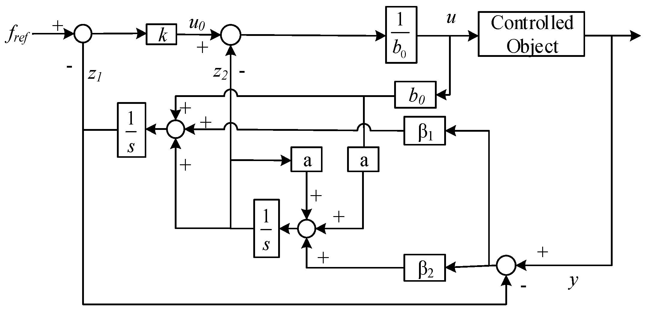
where e is the error factor. The variable z1x1, that is, z1, tracks the system output y. The variable z1x2, that is, z2, observes the total disturbance of the system. l1 is the feedback gain of the output observation error. l2 is the feedback gain of the disturbance observation error.
The parameter adjustment of LESO needs to achieve the target, as shown in Equation (4), which can be associated with ω0 using the bandwidth method.
lim t | z 1 x 1 | = 0 , lim t | z 2 x 2 | = 0
The poles of LESO are uniformly assigned to the observer bandwidth ω0:
λ 0 ( s ) = s 2 + l 1 s + l 2 = ( s + ω 0 ) 2
It can be understood from Equation (5) that the relationship between LESO adjustment parameters β1, β2, and ω0 is shown in Equation (6).
{ l 1 = 2 ω 0 l 2 = ω 0 2
The above design process is LESO without incorporating model information. The model information is identified as a disturbance which may lead to excessive observation information from the observer.

4.2. Design of Linear Extended State Observer Combined with Model Information

The generalized disturbance includes the disturbance caused by changes in the external environment, partial model information, gain of the control quantity, and the variation caused by uncertainty factors such as parameter deviation [24]. It can be seen that, when LESO estimates and compensates for the total disturbance, part of the model information that can be obtained in advance is included in the compensation range, which increases the observation burden of LESO on the total disturbance. To further reduce the lag of disturbance estimation, the state matrix and input matrix of LESO were improved. Part of the model information obtained through mathematical analysis is separated from the generalized perturbation and written into its coefficient matrix when constructing LESO.
The transfer function Gf(s) from active power P to angular frequency ω is obtained by analyzing the model:
G f ( s ) = 1 ω 0 ( s J + D ) + ω 0
Equation (7) is rewritten as:
y ˙ 1 ( t ) = a y 1 ( t ) + ( b 0 + Δ b 0 ) u ( t ) + w ( t )
where a = D J ; b 0 = 1 J ; u(t) = P(t).
f ( t ) is the actual sum of unknown perturbations.
f ( t ) = Δ b 0 u ( t ) + w ( t )
Then, Equation (7) can be written as
y ˙ 1 ( t ) = a y 1 ( t ) + b 0 u ( t ) + f ( t )
LESO design is as follows:
{ e = z 1 y z ˙ 1 = z 2 β 1 e + b 0 u z ˙ 2 = β 2 e + a b 0 u + a z 2
where e is the error factor. The variable z1x1, that is, z1, tracks the system output y. The variable z1x2, that is, z2, observes the total disturbance of the system. β1 is the feedback gain of the output observation error. β2 is the feedback gain of the disturbance observation error. The structure of LADRC-MI is shown in Figure 5.
The parameter adjustment of LESO needs to achieve the target as shown in Equation (12), which can be associated with ω0 by the bandwidth method.
lim t | z 1 x 1 | = 0 , lim t | z 2 x 2 | = 0
The poles of LESO are uniformly assigned to the observer bandwidth ω0:
λ 1 ( s ) = s 2 + β 1 s + β 2 = ( s + ω 0 ) 2
It can be understood from Equation (13) that the relationship between LESO adjustment parameters β1, β2, and ω0 is shown in Equation (14).
{ β 1 = 2 ω 0 + a β 2 = ( a + ω 0 ) 2
The above design process includes model information that can be obtained in advance. The addition of model information reduces the observation pressure on the observer and improves the observation speed. The addition of model information distinguishes LADRC-MI from LADRC.

4.3. Feedback Control Law Design

The linear feedback control law is designed as follows:
{ u 0 = k e 2 e 2 = f r e f z 1
where k is the controller gain; u0 is the virtual control quantity; and u is the actual output control quantity of the controller after disturbance compensation. By substituting u in the above formula into the first-order system object model, we can obtain:
y = f ( 0 ) + b 0 u = f ( 0 ) + b 0 × u 0 z 2 b 0 u 0
where f(0) is the system disturbance. Combined with Equations (15) and (16), the closed-loop characteristic equation of the controller can be obtained. The bandwidth method is used to associate the controller parameter k with the controller bandwidth ωc, and the pole is uniformly configured:
λ c ( s ) = s 2 + ( r + k ) s + k r   = ( s + r ) ( s + k )   = ( s + ω c ) 2
The relationship between the adjustment parameters and the bandwidth can be obtained from Equation (17):
k = ω c

4.4. Control Structure of LADRC-MI Combined with GFM

The GFM control structure introduced by LADRC-MI is shown in Figure 6. By adding the frequency modulation structure with LADRC-MI as the core in front of the GFM control loop, errorless frequency modulation can be realized.

5. Stability and Dynamic Performance Analysis of LADRC-MI

5.1. Stability Analysis of LADRC-MI

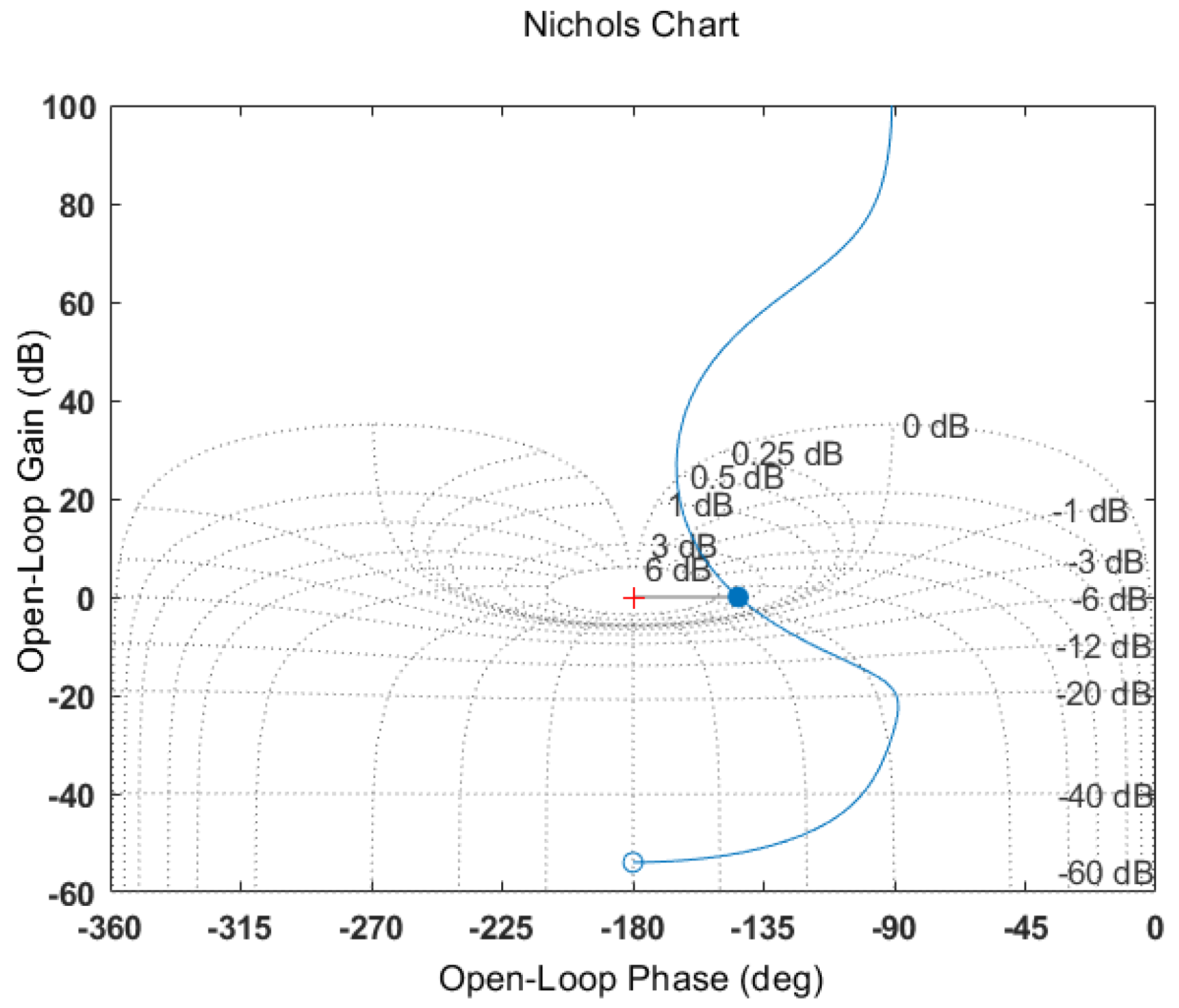
The stability of the LADRC-MI controller can be judged by the Nichols diagram, which is shown in Figure 7.
When the phase reaches −180°, the gain is about −54 dB below 0 dB, so the system is stable, and the gain margin is 54 dB. When the gain reaches 0 dB, the phase is −144°, which is 36° more than −180°, so the phase margin is 36°, and the phase is to the right of −180°, so the system is stable.

5.2. Anti-Disturbance Performance Analysis of LADRC-MI

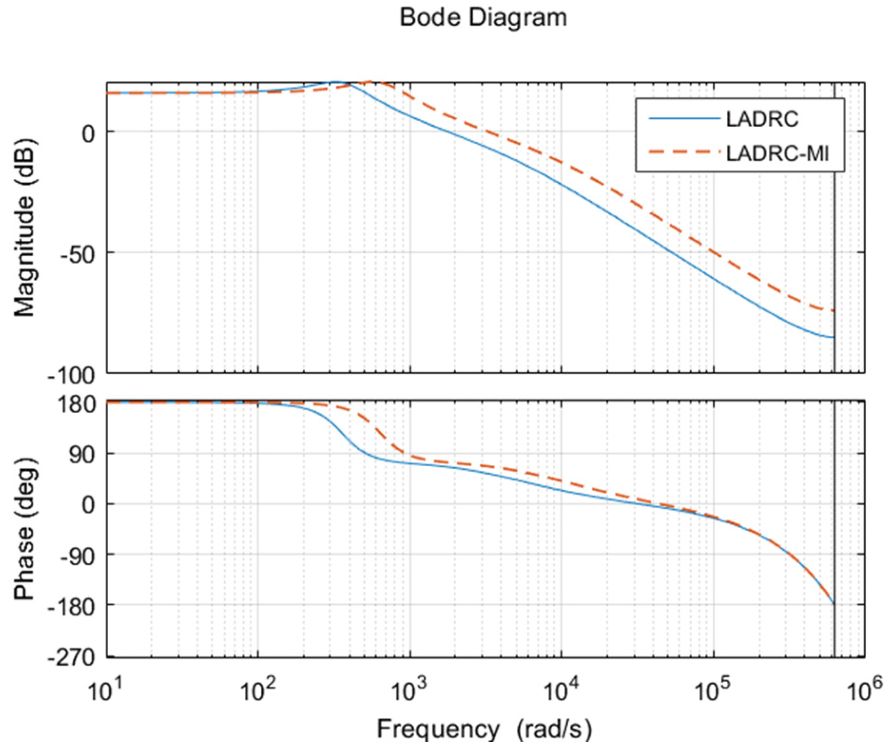
To verify the effectiveness of the proposed scheme in grid-connected inverter control, the disturbance immunity of LADRC-MI is compared with those of LADRC control schemes through Bode diagram analysis.
From Formula (7) above, the closed-loop frequency characteristics of traditional LADRC and LADRC-MI control systems can be compared. As shown in Figure 8, LADRC-MI exhibits better anti-power interference capability than traditional LADRC control in the middle-frequency band. At the same time, the phase lag of the system is reduced by LADRC-MI. The above analysis indicates that, in terms of anti-interference ability, LADRC-MI is better than traditional LADRC.

6. Simulation Verification and Analysis

To verify the effectiveness of the proposed scheme, a 10 kW grid-connected inverter model is built using Matlab 2019b simulation software. The specific parameters of the controller are shown in Table 2.

6.1. Analysis of Immunity Performance

To verify the effectiveness of the proposed LADRC-MI frequency modulation control method, three experimental conditions are set. There are two types of load surge events and one type of generator shutdown event. The performance of LADRC-MI, traditional LADRC controller, and PI controller are compared through three experiments. The parameter design of PI controller is mentioned in reference [25].
  • Working condition 1:
When set at 0.6 s, the load increases by 40%, that is, 4 kW. The simulation results are shown in Figure 9.
From Figure 9a, it is shown that, under the condition of a 40% sudden load increase, the frequency drop controlled by LADRC-MI is 49.99 Hz; the frequency drop controlled by LADRC is 49.96 Hz; and the frequency drop of the PI control is 49.90 Hz. The frequency drop range controlled by LADRC-MI is 75% less than that controlled by LADRC and 90% less than that controlled by PI. The above data show that the LADRC-MI control method exhibits a better control effect on the frequency.
In Figure 9b, the maximum overshoot value of the compensation power under the action of different controllers can be seen. LADRC-MI corresponds to 4.675 kW; the PI corresponds to 5.838 kW. The compensation power overmodulation under LADRC-MI control is 12.7% smaller than that under LADRC control and 63.3% smaller than that under PI control. The above data indicate that the LADRC-MI controller is better than the other two controllers.
Therefore, the effectiveness of the LADRC-MI controller proposed in this research is verified under working condition 1.
  • Working condition 2:
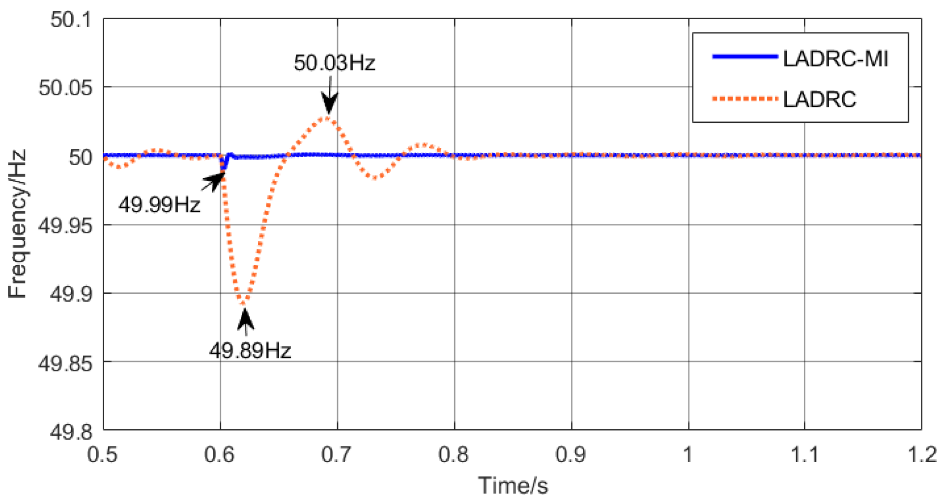
When set at 0.6 s, the load increases by 100%, that is, 10 kW. The simulation results are shown in Figure 10.
In Figure 10a, when the load suddenly increases by 100%, the frequency controlled by LADRC-MI decreases to 49.99 Hz; the frequency of LADRC control is reduced to 49.89 Hz; and the frequency of PI control decreases to 49.73 Hz. From the perspective of frequency reduction range, LADRC-MI control is 90% smaller than LADRC control and 96% smaller than PI control. The above data indicate that LADRC-MI controls the frequency better than the other two controllers.
The maximum overshoot of the compensation power under the action of each controller can be seen from Figure 10b. The power controlled by LADRC-MI is 12.21 kW. LADRC control corresponds to 12.57 kW; the effect of PI control is 15.30 kW. The compensation power overshoot under LADRC-MI control is 14% smaller than that under LADRC control and 58.3% smaller than that under PI control. The above data indicate that, under working condition 2, the LADRC-MI control method shows a good control effect on the compensating power.
Therefore, the effectiveness of the LADRC-MI control method proposed in this article is verified under the condition of working condition 2.
  • Working condition 3:
When set at 0.6 s, some generators are cut off from the grid, resulting in a decrease of 5 kW in grid power. The simulation results are shown in Figure 11.
In Figure 11a, a case is shown where some generators are cut off, resulting in a decrease in grid power. The frequency reductions in LADRC-MI control, LADRC control, and PI control are 49.99 Hz, 49.96 Hz, and 49.86 Hz. From the range of frequency decrease, LADRC-MI control is 75% lower than LADRC control and 92% lower than PI control. The above data indicate that the LADRC-MI control method exhibits a good control effect on the frequency.
In Figure 11b, the maximum overshoot of the compensation power for the three controllers can be obtained. Among them, LADRC-MI controls 6.30 kW. The maximum overshoot of the compensation power used for PI control in LADRC control is 7.66 kW. The control by LADRC-MI is 35% lower than that by LADRC and 51% lower than that by PI. The above data indicate that the LADRC-MI control method exhibits good control performance.
After the above verification and analysis, the dynamic performance of LADRC-MI is significantly improved compared with LADRC controller and PI controller, and the proposed scheme can effectively improve the frequency stability of the system.

6.2. Robustness Analysis under the Change of Moment of Inertia

The experiment was designed to evaluate and compare the robustness of LADRC and LADRC-MI under the condition of a varying moment of inertia J. The experiment was carried out under the condition of operating condition two with varying moment of inertia J. The characteristics of GFM control determine that its control effect is related to the moment of inertia, which affect the time of frequency stabilization and the frequency fluctuation range.
In Figure 12, the minimum frequency drop of LADRC-MI control is 49.99 Hz, the minimum frequency drop of LADRC control is 49.89 Hz, and the frequency stability time of LADRC-MI control is shorter.
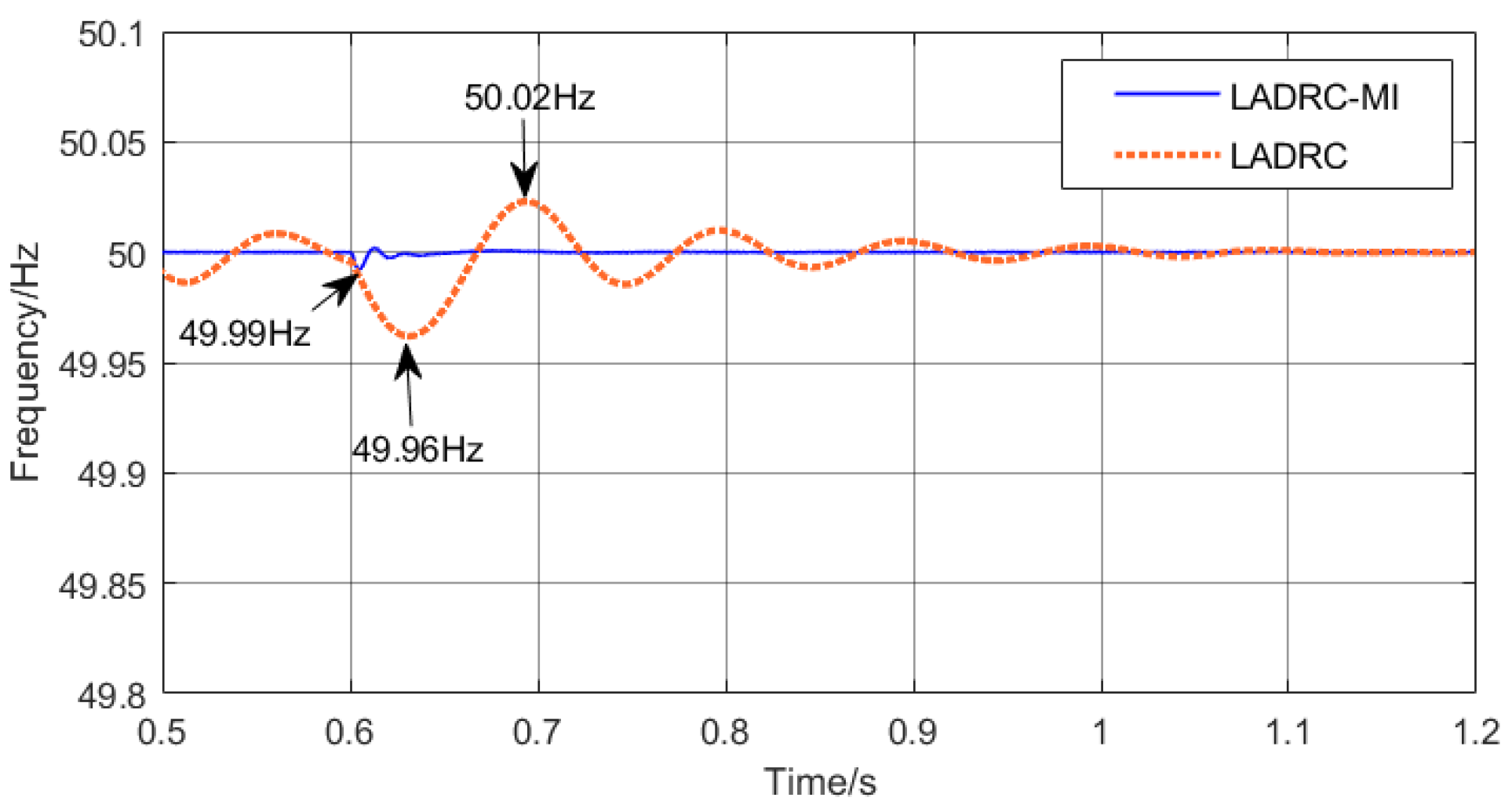
From Figure 13, it can be seen that the minimum frequency reduction for LADRC-MI control is 49.99 Hz, while for LADRC control, it is 49.96 Hz. This is due to the shorter frequency stabilization time of LADRC-MI control when the moment of inertia J changes from 0.2 to 0.5. The frequency stability rate based on LADRC-MI control is relatively fast, and the frequency reduction range is relatively small. Under different moments of inertia, the LADRC-MI control method also exhibits advantages over the LADRC control method.

7. Conclusions

Traditional system frequency support control typically adjusts output power based on the deviation between grid frequency and rated frequency. This traditional control method makes it difficult to obtain real-time disturbance information. A frequency modulation scheme combining the LADRC-MI controller with the GFM control method is proposed to address the frequency changes caused by uncertain disturbances in the system. Due to the combination of model information, the observation burden of disturbance information is reduced, and the response speed of the controller is accelerated. The anti-interference performance of the controller is improved. The experimental results show that the minimum frequency of the system after disturbance is improved, and the frequency stability of the system is good.

Author Contributions

Writing—original draft preparation, conceptualization, methodology, validation, Z.L., F.L. and P.Y.; formal analysis, investigation, resources, data curation, X.L. and G.Z.; writing—review and editing, visualization, supervision, project administration, Z.L. and F.L.; funding acquisition, P.Y. All authors have read and agreed to the published version of the manuscript.

Funding

This research was funded by The Marine Economic Development (Six Marine Industries) Special Fund Project of Guangdong Province, grant number No. GDNRC [2023]27.

Data Availability Statement

The datasets presented in this article are not readily available because [the data are part of an ongoing study]. Requests to access the datasets should be directed to [zhangguozun321.stud.tjut.edu.cn].

Conflicts of Interest

The authors declare no conflicts of interest.

Nomenclature

The variables of all figures are described in the table below.
SymbolParameterSymbolParameter
UdcDC-link voltageGTurbine valve position
CdcDC-link capacitanceHgInertia time constant
L1Grid-side filter inductanceDgDamping coefficient
CfGrid-side filter capacitanceTaTurbine time constant
L2Grid-side filter inductanceTgGovernor time constant
PNInverter rated powerKGPrimary frequency modulation coefficient.
PmGenerator mechanical powerPlLoad power
PGGenerator electromagnetic powerωgGrid frequency
fswSwitching frequencyfrefControl command value
Ua, Ub, UcInverter output voltageuLADRC controller output
Ia, Ib, IcInverter output currentySampling value of controlled object
Pe, QeInverter output powerb0Controller gain
Pref, QrefCommand value of inverter output powerkController gain
Id, IqThe dq component of the inverter output currentaController components
Ud, UqThe dq component of the inverter output voltageβ1LESO adjustment parameters
θThe angle generated by GFMβ2LESO adjustment parameters
EmVoltage amplitude generated by GFMJInertia time constant
ωGFM generated angular frequencyDDamping coefficient
ω0Initial angular frequencyId*,Iq*Reference value of dq component of the inverter output current
Ud*,Uq*Reference value of dq component of the inverter output voltage

References

  1. Sharma, D.; Sadeque, F.; Mirafzal, B. Synchronization of inverters in grid forming mode. IEEE Access 2022, 10, 41341–41351. [Google Scholar] [CrossRef]
  2. Harnefors, L.; Kukkola, J.; Routimo, M.; Hinkkanen, M.; Wang, X. A universal controller for grid-connected voltage-source converters. IEEE J. Emerg. Sel. Top. Power Electron. 2021, 9, 5761–5770. [Google Scholar] [CrossRef]
  3. Zhong, W.; Zhou, Y.; Wang, Z. Analysis of Safe and Stable Operation of New Power System. Hunan Electr. Power 2022, 42, 29–34. [Google Scholar]
  4. Li, G.; Liu, X.; Xin, Y. Review on Frequency Stability of power systems with high proportion of new energy. High Volt. Technol. 2024, 50, 1165–1181. [Google Scholar]
  5. Sadeque, F.; Sharma, D.; Mirafzal, B. Seamless grid-following to gridforming transition of inverters supplying a microgrid. In Proceedings of the 2023 IEEE Applied Power Electronics Conference and Exposition (APEC), Orlando, FL, USA, 19–23 March 2023; pp. 594–599. [Google Scholar]
  6. Liu, J.; Miura, Y.; Bevrani, H.; Ise, T. Enhanced Virtual Synchronous Generator Control for Parallel Inverters in Microgrids. IEEE Trans. Smart Grid 2017, 8, 2268–2277. [Google Scholar] [CrossRef]
  7. Rathnayake, D.B. Grid Forming Inverter Modeling, Control, and Applications. IEEE Access 2021, 9, 114781–114807. [Google Scholar] [CrossRef]
  8. Lasseter, R.H.; Chen, Z.; Pattabiraman, D. Grid-Forming Inverters: A Critical Asset for the Power Grid. IEEE J. Emerg. Sel. Top. Power Electron. 2020, 8, 925–935. [Google Scholar] [CrossRef]
  9. Li, Y.; Tian, Z.; Tang, Y. Stability analysis of small signal in isolated island microgrid considering interaction between GFM and GFL inverters. Power Autom. Equip. 2022, 42, 11–18. [Google Scholar]
  10. Tayyebi, A.; Grob, D.; Anta, A. Frequency stability of synchronous machines and grid-forming power converters. IEEE J. Emerg. Sel. Top. Power Electron. 2020, 8, 1004–1008. [Google Scholar] [CrossRef]
  11. Chen, W.; Xin, W.; Cheng, Z. Optical storage grid-connected power generation Control Technology Based on Virtual Synchronous Generator. Trans. China Electrotech. Soc. 2018, 33, 538–545. [Google Scholar]
  12. Ji, Y.; Su, J.; Ding, B. Off-grid switching and Fault Handling of micro-grid inverter VSG. Control Eng. 2021, 28, 1496–1504. [Google Scholar]
  13. Zhu, Z.; Zhang, C.; Zeng, X. Research on VSG Control Strategy of Microgrid Inverter Based on integral Compensation. Control Eng. 2021, 28, 979–983. [Google Scholar]
  14. Wang, Y.; Liu, B.; Duan, S. Transient performance comparison of modified VSG controlled grid-tied converter. In Proceedings of the 2019 IEEE Applied Power Electronics Conference and Exposition (APEC), Anaheim, CA, USA, 17–21 March 2019; pp. 3300–3303. [Google Scholar]
  15. Huang, L.B.; Xin, H.H.; Wang, Z. Transient stability analysis and control design of droop-controlled voltage source converters considering current limitation. IEEE Trans. Smart Grid 2019, 10, 578–591. [Google Scholar] [CrossRef]
  16. Sadeque, F.; Mirafzal, B. Frequency restoration of grid-forming inverters in pulse load and plug-in events. IEEE J. Emerg. Sel. Top. Ind. Electron. 2023, 4, 580–588. [Google Scholar] [CrossRef]
  17. Yu, J.; Sun, W.; Yu, J. Virtual synchronous Generator Control of grid-connected Inverter Based on Inertial Adaptive. Power Syst. Prot. Control 2022, 50, 137–144. [Google Scholar]
  18. Gursoy, M.; Mirafzal, B. Direct vs. indirect control schemes for gridforming inverters–Unveiling a performance comparison in a microgrid. IEEE Access 2023, 11, 75023–75036. [Google Scholar] [CrossRef]
  19. Zhu, J.; Wang, X.; Yu, L. Inertia and Damping Simulation control Strategy for Interconnected Asynchronous Power Grid VSC-HVDC. Proc. CSEE 2022, 42, 8089–8103. [Google Scholar]
  20. Saleem, M.; Choi, K.Y.; Kim, R.Y. Resonance damping for an LCL filter type grid-connected inverter with active disturbance rejection control under grid impedance uncertainty. Int. J. Electr. Power Energy Syst. 2019, 109, 444–454. [Google Scholar] [CrossRef]
  21. Chen, W.; Yang, J.; Guo, L. Disturbance-observer-based control and related methods-an overview. IEEE Trans. Ind. Electron. 2016, 63, 1083–1095. [Google Scholar] [CrossRef]
  22. Han, J. From PID to active disturbance rejection control. IEEE Trans. Ind. Electron. 2009, 56, 900–906. [Google Scholar] [CrossRef]
  23. Zhong, Q.-C.; Weiss, G. Synchronverters: Inverters that mimic synchronous generators. IEEE Trans. Ind. Electron. 2011, 58, 1259–1267. [Google Scholar] [CrossRef]
  24. Tao, L.; Wang, P.; Ma, X.; Wang, Y.; Zhou, X. Variable Form LADRC-Based Robustness Improvement for Electrical Load Interface in Microgrid: A Disturbance Response Perspective. IEEE Trans. Ind. Inform. 2024, 20, 432–441. [Google Scholar] [CrossRef]
  25. Kong, F.; Li, X.; Wu, J. Load frequency Control based on Nichols PID design method. Proc. CSEE 2012, 32, 79–85. [Google Scholar]
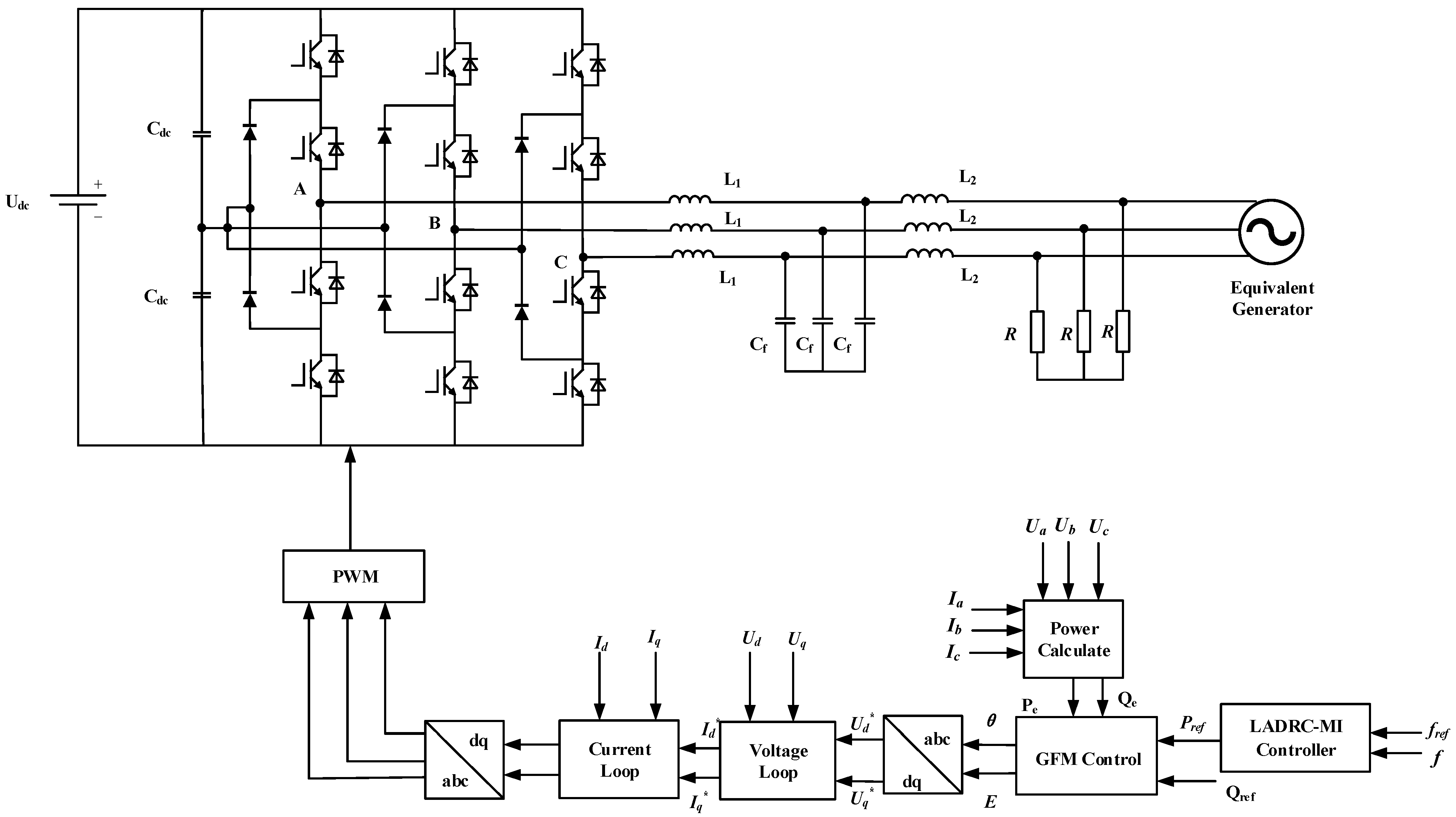
Figure 1. Overall block diagram of grid inverter system.
Energies 17 03282 g001
Figure 2. GFM controller structure.
Energies 17 03282 g002
Figure 3. Receiving power grid model.
Energies 17 03282 g003
Figure 4. LADRC control block diagram.
Energies 17 03282 g004
Figure 5. LADRC−MI structure.
Energies 17 03282 g005
Figure 6. Control structure of LADRC-MI combined with GFM.
Energies 17 03282 g006
Figure 7. Open−loop Nichols characteristic curve of LADRC-MI controller.
Energies 17 03282 g007
Figure 8. Comparison of frequency domain characteristics of LADRC−MI and LADRC.
Energies 17 03282 g008
Figure 9. Comparison of different controllers in working condition 1: (a) frequency waveform contrast; (b) power compensation waveform comparison.
Energies 17 03282 g009
Figure 10. Comparison of different controllers in working condition 2: (a) frequency waveform contrast; (b) power compensation waveform comparison.
Energies 17 03282 g010
Figure 11. Comparison of different controllers in working condition 3: (a) frequency waveform contrast; (b) power compensation waveform comparison.
Energies 17 03282 g011
Figure 12. Frequency control effect when J = 0.2.
Energies 17 03282 g012
Figure 13. Frequency control effect when J = 0.5.
Energies 17 03282 g013
Table 1. Simulation model parameters.
SymbolParameterValue
U dc DC-link voltage800 V
C dc DC-link capacitance4.7 mF
L 1 Grid-side filter inductance17 mH
C f Grid-side filter capacitance1 μF
L 2 Grid-side filter inductance0.1 mH
P N Inverter rated power10,000 W
P m Generator mechanical power101,365 W
P G Generator electromagnetic power100,000 W
F sw Switching frequency10 kHz
Table 2. Controller parameters.
SymbolParameterValue
Ddamping factor5.066
Jrotational inertia0.2
ω c LADRC-MI controller bandwidth800
ω 0 LESO bandwidth2300
Disclaimer/Publisher’s Note: The statements, opinions and data contained in all publications are solely those of the individual author(s) and contributor(s) and not of MDPI and/or the editor(s). MDPI and/or the editor(s) disclaim responsibility for any injury to people or property resulting from any ideas, methods, instructions or products referred to in the content.