Abstract
The aim of the article is to present the method of modeling the frequency response of the transformer windings with axial displacements. Frequency response analysis (often referred to as FRA or SFRA) is a powerful and sensitive method for testing the mechanical integrity of transformer cores, windings, and press frames in power transformers. The proper interpretation of FRA results is crucial in assessing winding faults. Computer modeling of transformer active part deformations is one way to expand knowledge about the impact of mechanical faults on the shape of the frequency response (FR) curve. The data collected from these models can be used as training data sets for artificial intelligence tools. An automatic tool developed from this approach would significantly improve the accuracy of the FRA method and simplify the interpretation and evaluation of results. The described study utilizes new types of lumped parameter models with input data obtained from the FEM analysis. The research conducted shows the influence of the winding axial deformation on the frequency response curve and provides information on the sensitivity of the FR curve’s shape to this type of deformation. A series of tests, which involved measuring and simulating typical axial damages, were conducted to evaluate the effectiveness of the presented algorithms.
1. Introduction
Power transformers are one of the most important equipment of the power system as they guarantee stable energy supply to consumers. Transformers are also the most expensive devices in the power grid. Power transformer failure usually generates costs several times higher than the cost of the unit itself [1]. For this reason, trouble-free and reliable operation of power transformers is crucial for maintaining energy security and for the proper management of power grid assets.
The frequency and impact of transformer failures are directly related to the technical condition of the unit. Proper monitoring of the technical condition of the transformer population using advanced diagnostic methods, both online and offline [2,3], allows energy market entities to plan investments, organize necessary repairs, and manage network assets effectively. International research on transformer reliability conducted by the CIGRE A2.37 working group [4] has shown that one of the most common causes of transformer failure is mechanical damage to the active part of the transformer. The working group collected 964 major failures of transformers with a voltage class of 69 kV and above. The collected data came from 56 utilities from 21 countries. The survey has shown that the main failure modes across all voltage classes are dielectrical (36.6%), mechanical (20%), electrical (16.5%), and thermal (10.9%). Taking into consideration the damage location, the main contributors were winding- (36.6%), tap changer- (23.2%), bushing- (14.4%), and core and magnetic circuit-related (4%) failures. The active parts of transformers are susceptible to mechanical damage primarily due to short-circuits, overvoltages, and seismic events. This damage can lead to bending, breaking, displacement, loosening, and vibration in both the winding and the magnetic circuit. The damaged windings with weakened insulation or partial discharges can function normally until the next switching or atmospheric overvoltage occurs, causing the damaged solid insulation to break down and leading to unit critical failure. Since defects are often latent, early identification and monitoring of winding damages can prevent serious transformer failure. Figure 1 shows several examples of axial damage that occurred in the windings of power transformers.
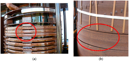
Figure 1.
Examples of typical axial damage to power transformer windings (marked in red circle): (a) discs with spacers falling out after the pressing plate lost its clamping force (coils closeup); (b) the effect of an axial mechanical force during a short-circuit on the winding (separated turns).
To assess and determine the mechanical condition of the winding, the core, and the leads, the frequency response analysis (FRA) method is used. FRA measurement is currently one of the standard post-production tests of power transformers, and it is also performed after short-circuit events. FRA is a comparative method, which requires a reference measurement on a new unit or under undamaged conditions to evaluate the results. The evaluation involves determining the differences in the compared curves. Nevertheless, the biggest challenge is finding the correlation between changes in the curves and specific damage to the winding. In some cases, it is still not possible to determine the scope and location of smaller damages, but only to identify dangerous symptoms indicating damage. Despite this limitation, the FRA method is still useful because it provides a complete picture of the mechanical condition of the windings without the need to open the tank. Current research in the field of FRA focuses on developing tools to help interpret measurement results [5], including statistical methods [6,7,8] and methods based on artificial intelligence [9,10,11].
Modeling the frequency response (FR) of the winding is one of the methods of increasing the interpretability of FRA results. Frequency response modeling was recommended by the CIGRE group over a decade ago [12] as a way to collect information on many deformation events and precisely determine their impact and scale on the shape of the FRA curve. However, modeling the frequency response of a winding is a complex problem, and the model must meet several conditions at the same time, as follows:
- The simulated FRA characteristic should fully correspond to the characteristic obtained from the measurement in the entire frequency range. Any shift in the curve may lead to an incorrect interpretation of the obtained results;
- Measurement over a wide frequency range involves combining several phenomena that the model must consider. It starts with magnetic phenomena at low frequencies and ends with wave phenomena at high frequencies;
- The model must enable easy access to the geometry of the modeled winding, its parameters, and its topology. This will allow for locating and identifying the type of damage.
Over the years, many studies have been carried out to create models of the active parts of transformers for FRA analysis. The most commonly used models are the lumped parameter ladder network models, in which the electrical parameters are connected and represent a part of the winding, usually a disc or a single turn. The interactions between structure elements are represented by mutual inductances and additional capacitances. Simulating axial and radial displacements of the windings can be achieved by changing individual parameters in the model. This can help identify faults in the winding and their impact on the FRA curve. The model topology proposed by Rahimpour [13] at the beginning of the 21st century has been generally accepted and is used in other studies. The RLC parameters of the model can be computed accurately using estimation or numerical methods [14,15,16].
The influence of changes in individual electrical parameters on the frequency response of the model has been thoroughly investigated. Abu-siada et al. [17] conducted research in which they examined the impact of changes in the values of electrical parameters by ±10% on the FR curve. Hashemnia et al. in [18,19] investigated the correlation between various axial and radial displacement levels with the percentage change in all transformer equivalent circuit parameters caused by displacement faults.
According to the research conducted on the simulation of the FRA signature, the accuracy of lumped parameter models depends on the number of elements included in the model, particularly those intended to represent couplings between discs or windings [20]. However, it is unclear what level of accuracy in mapping the parameters in the circuit model is necessary to accurately simulate the FRA curve and match the actual measurement with sufficient precision. In most of the proposed models, inter-turn capacitances are omitted, the exact structure of the winding and mutual inductances between the coils are not considered, or the corresponding winding is simplified to several discs [18,21]. Such simplifications can reduce the accuracy of the results, particularly in axial displacement simulation. In [22], the authors underline the importance of considering intersection capacitances and mutual inductances between windings for accurate simulation of axial displacement faults. The authors in [15,23] propose more accurate models with lumped parameters, in which the winding structure, inter-turn capacitances, and all mutual inductances are taken into account. The proposed models were utilized to analyze the impact of various deformations, such as coil short-circuits and axial and radial damages on the FR curve. The simulation results, which were compared with the measurement results of the real object, indicate compliance in terms of the direction and trend of curve changes. However, the proposed models still do not reproduce the FRA curve accurately enough for reliable identification of internal damages and assessment of their scale. In [24], the authors present a method using FEM simulation and a lumped element circuit to obtain FRA traces, along with an optimization method to improve capacitive parameters from estimated values. They obtain good accuracy, but it should be noted that they use a laboratory model of an air-core winding to verify their method, so there is no verification on a real unit.
The paper introduces a new method of modeling the frequency response of transformer windings with axial displacements. The simulation method presented in the paper encounters difficulties in accurately representing changes in the frequency response curves and specific axial damages to the winding. Currently, there is no optimal tool available that can sufficiently and accurately simulate the FR curve of a real HV transformer. The model proposed in this study aims to fill this gap. The development of a database of simulated damages is a step toward creating a tool that can automate the interpretation of FRA measurement results.
Axial displacements are one of the most commonly occurring deformations of the transformer windings, so it is important to understand their impact on the shape of the FR curve. The described study utilizes new types of lumped parameter ladder network models, with input data obtained from the FEM analysis. To perform the numerical analysis, it was necessary to develop a computer model which correspond to the dimensions and material parameters of the actual object. The research shows how winding axial deformation affects the frequency response curve and includes information on the sensitivity of the FR curve’s shape to this type of deformation. A series of tests were conducted, which involved measuring and simulating typical axial damages, to evaluate the effectiveness of the proposed algorithms.
2. Lumped Parameter Circuit Models
This study presents three different configurations of lumped parameter circuit models. For each configuration, there is a numerical algorithm that is based on equations resulting from Kirchhoff’s laws. These algorithms allow us to obtain the values of voltages and currents in the nodes of the circuit model. The proposed models, in addition to the values of the RLC parameters of each turn, consider mutual inductances and mutual capacitances between all turns of the analyzed winding. It is important to note that in the proposed models it is possible to consider the parallel connections between the coils. The only electrical element that is not present in the circuit models is the earth resistance. The resistance to the ground depends on the resistivity of the insulation medium, which is electrical insulating oil. Insulating liquids have a resistivity of about GΩm, resulting in very low resistance that does not influence the FRA characteristic and can, therefore, be omitted.
2.1. Model in Configuration Π
The model of a single turn in the Π configuration is shown in Figure 2. The model allows for parallel connections of windings, where K is the number of parallel windings and M is a number of turns in series. The model of turn number M(k − 1) + m includes self-inductance LM(k−1)+m, self-capacitance CM(k−1)+m, and self-resistance RM(k−1)+m, as well as the mutual inductance LM(k−1)+m,j and the mutual capacitance CM(k−1)+m,j between the turns M(k − 1) + m and any j. The characteristic feature of the Π model is the capacitance divided in half for both input and output.
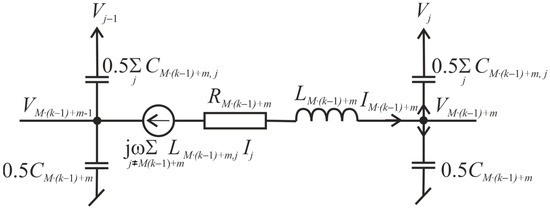
Figure 2.
Single turn model in the Π configuration.
The turn number is given by the expression M(k − 1) + m, where k = 1…K, m = 1…M. The beginning of the winding is m = 1 and the end of the winding is m = M. The coil order changes from m = 1…M and then from k = 1…K.
The input voltage Vin is known. The voltage equation for the first coil m = 1 is as follows:
The voltage equation for the last coil m = M is as follows:
The current equation for the last coil m = M is as follows:
The voltage equation for the other coils m = 2…M − 1 is as follows:
The current equation for the other coils m = 1…M − 1 is as follows:
2.2. Model in Configuration Γ
The model of a single turn in the Γ configuration with a connection to the next one is shown in Figure 3. In the Γ model, the self-capacitance of the turn is concentrated on the right side of the output. The coils are numbered using the same method as in the Π configuration model, and the model can consist of N = M·K turns connected in parallel.

Figure 3.
Single turn model in the Γ configuration.
The beginning of the winding is m = 1 and the end of the winding is m = M. The coil order changes from m = 1…M and then from k = 1…K. The input voltage Vin is known. The voltage equations for the first coil m = 1 is as follows:
The voltage equation for the last coil m = M is as follows:
The current equation for the last coil m = M is as follows:
The voltage equation for the other coils m = 2…M − 1 is as follows:
The current equation for the other coils m = 1…M − 1 is as follows:
2.3. Model in Configuration T
The last proposed configuration is the T-structure model, illustrated in Figure 4. It differs from the other models in that the self-capacitance is concentrated within the network element. Both the input and output of the T model have an inductive character. The current number is given by the following expression: (M + 1)(k − 1) + m. The coils are numbered using the same method as in the previous configurations.

Figure 4.
Single turn model in the Τ configuration.
For the network of M coils connected in K parallel branches, the T-structure model gives the following equations. As Vin is known, the voltage equation for the first coil m = 1 is as follows:
The voltage equation for the last coil m = M is as follows:
The voltage equation for the other coils m = 2…M is as follows:
The current equation for all coils m = 1…M is as follows:
The current equation for the output m = M is as follows:
3. Model Parameters Computation
The electrical parameters of the given model were computed using a numerical method. Hence, a computer model of the analyzed winding in FEM software (ANSYS Maxwell v.19.2) was prepared. As previously mentioned, to reproduce the FR curve with high precision, it is necessary to represent every turn in the analyzed winding. This approach enables the inclusion of all mutual inductances and inter-turn capacitances into the lumped parameter circuit model. Moreover, dividing the winding into individual turns allows for accurate and effortless modeling of the axial displacements.
The software used for the calculations was ANSYS Maxwell v.19.2, in which the impedance and capacitance matrices necessary for the circuit models can be calculated based on the distribution of the electromagnetic field.
The electrostatic solver provides the distribution of the electrical field by determining the value of the scalar electric potential from the following differential equation:
where φ is the scalar potential of the electrostatic field induced by charge with density ρ, ε0 is the vacuum permittivity, and εr is the relative permittivity.
The values of self- and mutual capacitances are determined by calculating the electric field energy Wij between two conductors i and j, as follows:
where D is the vector of the electrical potential, E is the vector of the electric field intensity, Cij is the capacitance between conductor i and j, v is the voltage between conductors, and Ω is the volume.
The distribution of a steady-state, time-varying magnetic field at a given frequency is determined by solving the following field equation:
where A is the magnetic vector potential, φ is the electric scalar potential, μ is the magnetic permeability, ω is the angular frequency at which all quantities are oscillating, γ is the conductivity, and ε is the permittivity.
The values of self- and mutual inductances are delivered by calculating the energy of the electromagnetic field as follows:
where: B—vector of the magnetic induction, H—vector of the magnetic field intensity, Lij—the inductance, Ω—volume.
The resistance values of the turns are determined based on the active power losses P:
where J is the density of the current flow, Ipeak is the peak value of the current, γ is the conductivity of the wires, and Ω is the volume.
Detailed information on creating the impedance matrix and capacitance matrix is available in the technical documentation of the used software.
It is important to note that when calculating inductance and resistance, the impact of eddy currents in conductors, the proximity effects and the skin effect should be considered. This is because field analysis is carried out over a wide frequency range. As the frequency increases, the concentration of current density inside the wires varies, which results in a higher active resistance in the tested turns than in the static case. Conversely, the value of inductance will be slightly lower. To obtain accurate results, particularly above 1 MHz, it is necessary to discretize the area with a dense finite element mesh to account for the frequency-dependent phenomena.
Table 1 shows the RLC parameters obtained for several sample turns of the tested 60-turn coil. Table 1 presented the self- and mutual electrical parameter values for selected turns—from the beginning, middle and end of the analyzed winding.

Table 1.
Self- and mutual electrical parameters of the tested 60-turn coil obtained in FEM software.
4. Experimental Studies
A series of tests were conducted to assess the effectiveness of the presented algorithms for modeling transformer winding axial displacements. These tests involved measuring and simulating typical axial damages on a 60-turn air coil, which was extracted from an 800 kVA distribution transformer and had a diameter of 600 mm.
4.1. Modeling of the Coil without Deformations
The object being tested is a part of a disc winding that was removed from the core. The turns are connected in series and arranged into 3 double-layer discs, each containing 20 turns. A representative photo of the coil is shown in Figure 5. During the FRA test, the voltage signal was applied to the beginning of the coil and recorded at its end. An Omicron FRAnalyzer device was used to measure the frequency response of the coil in the range of 20 Hz to 10 MHz. The measurement was performed in an end-to-end configuration where the measurement signal was applied at the beginning of the coil and recorded at its end. The configuration of the measurement is present in Figure 6, and the result of this measurement is shown in Figure 7.
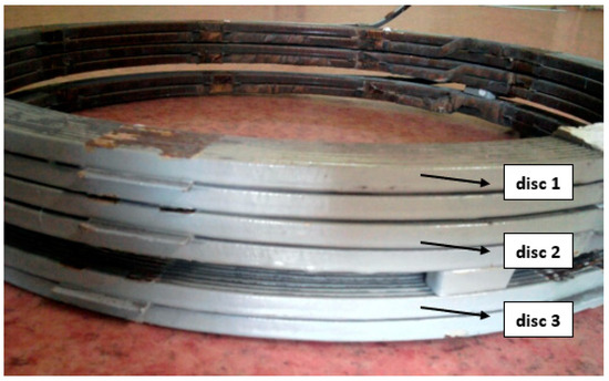
Figure 5.
Tested 60-turn coil consisting of 3 double-layer discs, with a controlled deformation introduced by removing the spacers between disc 1 and disc 2.
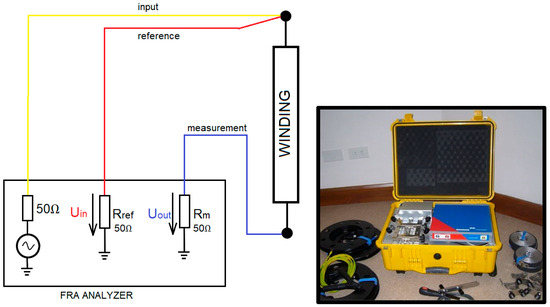
Figure 6.
The end-to-end configuration of the FRA measurement of the analyzed coil and the Omicron FRAnalyzer device.
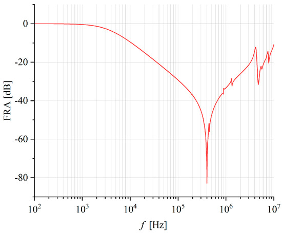
Figure 7.
Frequency response of a 60-turn air coil without deformation—fingerprint measurement.
Based on the geometric dimensions of the tested coil, a 2D computer model was developed in the ANSYS Maxwell software, as presented in Figure 8. The coil was divided into separate turns in the field model to determine electrical parameters for each turn individually and to analyze the interaction between all turns. Numerical analysis was conducted for frequencies of 100 Hz, 1000 Hz, 10 kHz, 100 kHz, and 1 MHz. The self RLC parameters and mutual parameters for the other frequencies were obtained through linear interpolation.
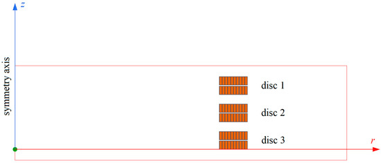
Figure 8.
2D coil model in FEM software (cylindrical symmetry).
The self- and mutual electrical parameters of the coils obtained during the FEM numerical analysis were used as input data in the circuit calculation algorithms described in Section 2. The proposed algorithms calculated the values of currents and voltages in the nodes of the circuit model and ultimately determined the voltage value at the model output. The output voltage is necessary to find the transfer function and the amplitude of the FRA measurement signal. Figure 9 shows the characteristics obtained using circuit algorithms in the Π, Γ, and Τ configurations. The modeled curves are compared with the measurement results of the test object. The results from simulations and FRA measurements on a 60-turn, non-deformed air coil show that the presented lumped parameter circuit models are highly accurate in reproducing the frequency response.
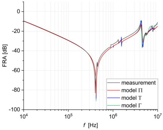
Figure 9.
Frequency response curves of a 60-turn coil modeled using circuit algorithms in the Π, Γ, and Τ configurations compared with the results of FRA measurements.
Minor differences can be observed in the shift in the main resonance (referred to as the first resonance) within the 400 kHz to 1 MHz range, as well as its corresponding value within the same range. These variations are attributed to asymmetries in the tested object, which may have occurred during the removal of the coil from the core. When the winding is dismantled, there are inevitably small axial and radial displacements due to the necessity of loosening or disentangling the winding from the core. Nonetheless, the frequency response model of the FRA accurately represents all resonances across the entire measurement frequency range.
The results shown above indicate that the assumptions made in the model, which consider the interaction between all turns by introducing mutual inductance and mutual capacitances, lead to high compliance across the entire measurement frequency range. Therefore, the next step involved examining the suitability of the proposed solution for modeling the axial deformations of windings.
4.2. Modeling of the Axial Deformations
Axial deformation usually occurs in real winding due to the loss of spacers between the discs caused by dynamic forces, like a short-circuit event. Movements of the discs in the coil cause changes in the capacitance values, which are visible in the frequency response as shifts in the curve along the frequency. The influence of the axial deformation on the frequency response curve is shown in Figure 10.
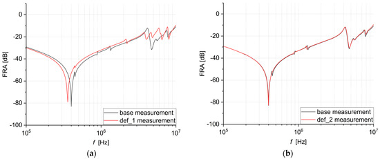
Figure 10.
Comparison of the fingerprint measurement (without deformation) for a 60-turn coil and the measurements after controlled deformation: (a) deformation no. 1—lowering discs; (b) deformation no. 3—disc separation.
The test involved introducing three controlled deformations to the real object (Figure 5). Initially, the distance between the discs in the coil was 4 mm. The axial deformations were implemented by changing the distance between the discs. An FRA measurement was conducted on an actual object for each deformation. Figure 11 shows the field models of all three introduced deformations compared to the undamaged coil.
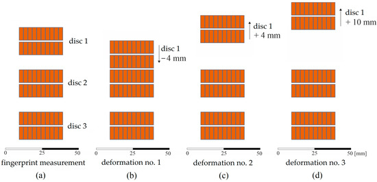
Figure 11.
Axial deformations implemented on the 60-turn coil model: (a) base model—no deformation, (b) deformation 1—lowering disc no. 1 and disc no. 2 by 4 mm, (c) deformation 2—lifting disc no. 1 by 4 mm, and (d) deformation 3—lifting disc no. 1 by 10 mm.
The field models were prepared similarly to the model without deformation, utilizing ANSYS Maxwell software. Then, the electromagnetic field’s FEM analysis was used to determine the electrical parameters, which were later applied to the proposed lumped parameter circuit model. The results of the study are described below.
4.2.1. Modeling of Deformation No. 1
The first controlled deformation was performed on the tested coil by removing the spacers between the discs. This resulted in a shift in the FRA characteristics towards the left. Additionally, changes in the geometry of the model caused small resonances visible at around 1 MHz and above 5 MHz. A comparison of the FR of the 60-turn coil without deformation and the FR measured after deformation no. 1 can be seen in Figure 10a.
Figure 12 shows the frequency response of the 60-turn coil model with deformation no. 1, determined using 3 circuit algorithms in the Π, Γ, and Τ configurations. The modeled characteristics are compared with the FRA measurement performed for this coil.
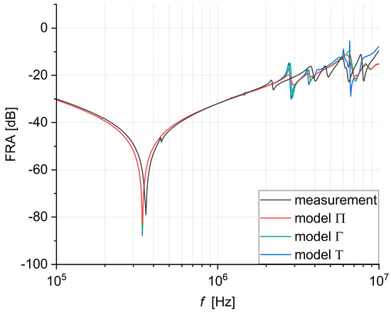
Figure 12.
Frequency responses modeled using circuit algorithms in the Π, Γ, and Τ configurations compared with the measurement result for a 60-turn coil with deformation no. 1.
4.2.2. Modeling of Deformation No. 2
Deformation no. 2 involved doubling the distance between disc 1 and disc 2, causing a slight shift in the FRA characteristics. Changing the model geometry led to a shift in the small resonances at approximately 1 MHz to the left. Figure 10b compares the frequency response (FR) of the analyzed coil with deformation no. 2 to the FR of the coil without deformation. The influence of increasing the distance between the discs is much smaller than in the case of bringing them closer together (deformation no. 1).
Figure 13 presents a comparison between the measured frequency response of the coil with deformation no. 2 and the ones modeled with the proposed numerical algorithms.
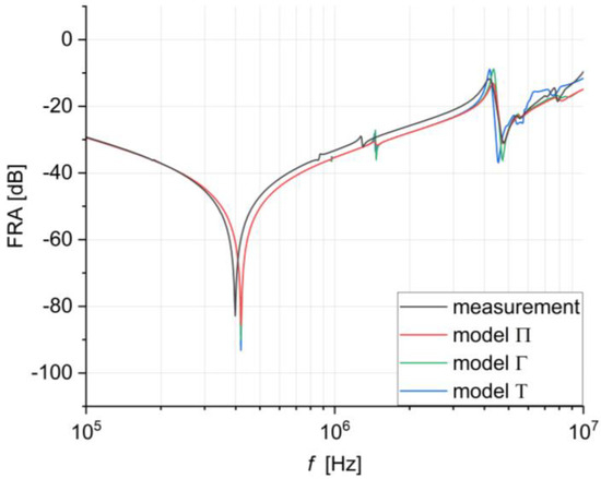
Figure 13.
Frequency responses modeled using circuit algorithms in the Π, Γ, and Τ configurations compared with the measurement result for a 60-turn coil with deformation no. 2.
4.2.3. Modeling of Deformation No. 3
The last, third axial deformation was implemented by increasing the distance between disc 1 and disc 2 by 10 mm from its original distance. Since this deformation was like the second one, its effects were also similar. The result of both deformations is a shift in the frequency response characteristics towards the left, which is most noticeable at a frequency of approximately 1 MHz. As in the case of the previous deformations, the modeling results compared with the measured curve are presented on a common plot in Figure 14.
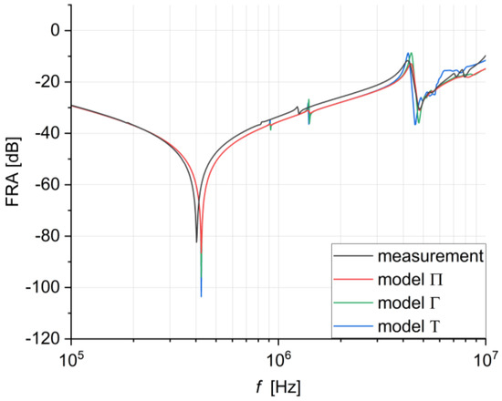
Figure 14.
Frequency responses modeled using circuit algorithms in the Π, Γ, and Τ configurations compared with the measurement result for a 60-turn coil with deformation no. 3.
5. Conclusions
The simulation results and FRA measurement of a 60-turn, non-deformed air coil show that the presented lumped parameter circuit models can accurately replicate the frequency response. This proves that the assumptions made in the model, which consider the interactions between all turns by introducing mutual inductances and mutual capacitances, enable high compliance over the entire measurement frequency range.
In all cases considered, the best agreement between the simulation and the FRA measurement is reached for the Π-structure model. However, the algorithms in all three configurations accurately reflect the direction of changes caused by the deformation. Axial deformations mainly affect the values of inter-turn capacitances, causing shifts in the FRA curves in the low-frequency range. This finding is valuable for modeling this type of deformation because it indicates that it is enough to add an element responsible for the capacitance change in the circuit model to simulate the deformations correctly.
In the FRA measurement simulation, the primary concern is the accurate identification of the first resonance, which depends on the self-inductance and total capacity of the winding. The phenomenon of the first parallel resonance can be observed in the results of FRA measurements performed in an end-to-end configuration where the measurement signal is applied at the beginning of the winding and recorded at its end. It usually represents the largest attenuation value in the measured frequency response curve. The FRA curve starts with a declining edge, indicating the inductive nature of the winding in this frequency range. The system’s behavior changes at the first parallel resonance, caused by the interaction between the magnetizing inductance and the winding’s capacitance to the ground. Following this resonance, the amplitude values begin to rise due to the dominant influence of the winding capacitance, marking the end of the low-frequency range at the inflection point of the rising edge. The larger amplitude of the first resonance obtained in the simulated FR curves is caused by the too-low Q-factor of the circuit model. The Q-factor value is related to the resistance of the conductor and requires very accurate numerical calculations with tense finite element mesh, especially at high frequencies.
After comparing the performance of the three models presented, it can be concluded that when modeling controlled deformations of a 60-turn coil, the T model shows greater divergence at very high frequencies. This is because the input of the entire circuit model in this model is inductive, forcing the high-frequency measurement signal to pass through the inductance. Considering the slightly greater complexity of the T-structure model and the larger size of the resulting matrix, it should be considered the least useful in modeling windings.
Modeling the frequency response of transformer windings is a method that can help interpret FRA results. While the conceptual idea of modeling deformations and their impact on the FRA curve is simple, creating an effective model in practice poses challenges, particularly in the frequency range above 500 kHz. The analysis of the simulation results obtained in this paper indicates that the developed numerical algorithm makes it possible to determine the frequency response in the entire measurement frequency spectrum, but there are still several issues that require further research. In the case of the circuit-field model used, its accuracy is determined by the accuracy of the winding RLC parameters generated by FEM analysis. Determining the parameters of single turns at high frequencies, when a very dense mesh of finite elements must be used due to the skin effect and eddy currents, requires the modification of the field model. In future work, the accuracy of the capacity determination in the model will be crucial. During the analysis in the FEM software, it is assumed that the entire surface of the conductor is equipotential, but in reality, at high frequencies, the current is displaced from the inside of the conductor and flows only in its corners. This discrepancy may lead to differences in the actual values of capacitance and those determined using the electrostatic model. Another research problem that requires further analysis is the mapping of the Q-factor of the circuit. The value of the Q-factor is related to the resistance of the conductor and requires precise numerical calculations, especially at high frequencies.
Author Contributions
Conceptualization, K.T. and K.M.G.; Methodology, K.T. and K.M.G.; Software, K.T.; Validation, K.T. and K.M.G.; Formal analysis, K.T.; Investigation, K.T.; Resources, K.T.; Writing—original draft, K.T.; Writing—review & editing, K.T. and K.M.G.; Visualization, K.T.; Supervision, K.M.G. All authors have read and agreed to the published version of the manuscript.
Funding
This research received no external funding.
Data Availability Statement
The original contributions presented in the study are included in the article, further inquiries can be directed to the corresponding author.
Conflicts of Interest
The authors declare no conflict of interest.
References
- Dong, M.; Zheng, H.; Zhang, Y.; Shi, K.; Yao, S.; Kou, X.; Ding, G.; Guo, L. A Novel Maintenance Decision Making Model of Power Transformers Based on Reliability and Economy Assessment. IEEE Access 2019, 7, 28778–28790. [Google Scholar] [CrossRef]
- Tenbohlen, S.; Coenen, S.; Djamali, M.; Muller, A.; Samimi, M.H.; Siegel, M. Diagnostic Measurements for Power Transformers. Energies 2016, 9, 347. [Google Scholar] [CrossRef]
- Jin, L.; Kim, D.; Abu-Siada, A. State-of-the-Art Review on Asset Management Methodologies for Oil-Immersed Power Transformers. Electr. Power Syst. Res. 2023, 218, 109194. [Google Scholar] [CrossRef]
- Tenbohlen, S.; Jagers, J.; Bastos, G.; Desai, B.; Diggin, B. Cigré Brochure 642 A2.37-Transformer Reliability Survey. CIGRE Tech. Broch. 2015, 642, 94–102. [Google Scholar]
- Kakolaki, S.E.H.; Hakimian, V.; Sadeh, J.; Rakhshani, E. Comprehensive Study on Transformer Fault Detection via Frequency Response Analysis. IEEE Access 2023, 11, 81852–81881. [Google Scholar] [CrossRef]
- Jianqiang, N.; Zhongyong, Z.; Shan, T.; Yu, C.; Chenguo, Y.; Chao, T. The Actual Measurement and Analysis of Transformer Winding Deformation Fault Degrees by FRA Using Mathematical Indicators. Electr. Power Syst. Res. 2020, 184, 106324. [Google Scholar] [CrossRef]
- Banaszak, S.; Szoka, W. Transformer Frequency Response Analysis With the Grouped Indices Method in End-to-End and Capacitive Inter-Winding Measurement Configurations. IEEE Trans. Power Deliv. 2020, 35, 571–579. [Google Scholar] [CrossRef]
- Bigdeli, M.; Abu-Siada, A. Clustering of Transformer Condition Using Frequency Response Analysis Based on K-Means and GOA. Electr. Power Syst. Res. 2022, 202, 107619. [Google Scholar] [CrossRef]
- Liu, J.N.; Zhao, Z.Y.; Tang, C.; Yao, C.G.; Li, C.X.; Islam, S. Classifying Transformer Winding Deformation Fault Types and Degrees Using FRA Based on Support Vector Machine. IEEE Access 2019, 7, 112494–112504. [Google Scholar] [CrossRef]
- Zhao, Z.; Yao, C.; Tang, C.; Li, C.; Yan, F.; Islam, S. Diagnosing Transformer Winding Deformation Faults Based on the Analysis of Binary Image Obtained from FRA Signature. IEEE Access 2019, 7, 40463–40474. [Google Scholar] [CrossRef]
- Elahi, O.; Behkam, R.; Gharehpetian, G.B.; Mohammadi, F. Diagnosing Disk-Space Variation in Distribution Power Transformer Windings Using Group Method of Data Handling Artificial Neural Networks. Energies 2022, 15, 8885. [Google Scholar] [CrossRef]
- Picher, P.; Lapworth, C.J.; Noonan, T.; Christian, J.; Alpatov, M.; Bormann, D.; Breytenbach, R.; Dick, P.; Drobyshevski, A.; Dumbrava, I.; et al. Cigré Brochure 342 A2.26—Mechanical Condition Assessment of Transformer Windings Using Frequency Response Analysis; CIGRE Technical Brochure; CIGRE: Paris, France, 2008. [Google Scholar]
- Rahimpour, E.; Christian, J.; Feser, K.; Mohseni, H. Transfer Function Method to Diagnose Axial Displacement and Radial Deformation of Transformer Windings. IEEE Trans. Power Deliv. 2003, 18, 493–505. [Google Scholar] [CrossRef]
- Abu-Siada, A.; Mosaad, M.I.; Kim, D.; El-Naggar, M.F. Estimating Power Transformer High Frequency Model Parameters Using Frequency Response Analysis. IEEE Trans. Power Deliv. 2020, 35, 1267–1277. [Google Scholar] [CrossRef]
- Zhao, X.Z.; Yao, C.G.; Abu-Siada, A.; Liao, R.J. High Frequency Electric Circuit Modeling for Transformer Frequency Response Analysis Studies. Int. J. Electr. Power Energy Syst. 2019, 111, 351–368. [Google Scholar] [CrossRef]
- Cheng, B.; Yang, Y.; Shen, S.; Wang, Z.; Crossley, P.; Wilson, G.; Fieldsend-Roxborough, A. Parameter Identification of Transformer Lumped Element Network Model through Genetic Algorithm-Based Gray-Box Modelling Technique. IET Electr. Power Appl. 2024, 18, 265–277. [Google Scholar] [CrossRef]
- Abu-Siada, A.; Hashemnia, N.; Islam, S.; Masoum, M.A.S. Understanding Power Transformer Frequency Response Analysis Signatures. IEEE Electr. Insul. Mag. 2013, 29, 48–56. [Google Scholar] [CrossRef]
- Hashemnia, N.; Abu-Siada, A.; Islam, S. Improved Power Transformer Winding Fault Detection Using FRA Diagnostics—Part 1: Axial Displacement Simulation. IEEE Trans. Dielectr. Electr. Insul. 2015, 22, 556–563. [Google Scholar] [CrossRef]
- Hashemnia, N.; Abu-Siada, A.; Islam, S. Improved Power Transformer Winding Fault Detection Using FRA Diagnostics—Part 2: Radial Deformation Simulation. IEEE Trans. Dielectr. Electr. Insul. 2015, 22, 564–570. [Google Scholar] [CrossRef]
- Gawrylczyk, K.M.; Banaszak, S. Recent Developments in the Modelling of Transformer Windings. Energies 2021, 14, 2798. [Google Scholar] [CrossRef]
- Liu, S.; Liu, Y.; Li, H.; Lin, F. Diagnosis of Transformer Winding Faults Based on FEM Simulation and On-Site Experiments. IEEE Trans. Dielectr. Electr. Insul. 2016, 23, 3752–3760. [Google Scholar] [CrossRef]
- Ahour, J.N.; Seyedtabaie, S.; Gharehpetian, G.B. Modified Transformer Winding Ladder Network Model to Assess Non-Dominant Frequencies. IET Electr. Power Appl. 2017, 11, 578–585. [Google Scholar] [CrossRef]
- Zhou, L.J.; Jiang, J.F.; Li, W.; Wu, Z.Y.; Gao, S.B.; Guo, L.; Liu, H.W. FRA Modelling for Diagnosing Axial Displacement of Windings in Traction Transformers. IET Electr. Power Appl. 2019, 13, 2121–2127. [Google Scholar] [CrossRef]
- Suassuna de Andrade Ferreira, R.; Picher, P.; Meghnefi, F.; Fofana, I.; Ezzaidi, H.; Volat, C.; Behjat, V. Reproducing Transformers’ Frequency Response from Finite Element Method (FEM) Simulation and Parameters Optimization. Energies 2023, 16, 4364. [Google Scholar] [CrossRef]
Disclaimer/Publisher’s Note: The statements, opinions and data contained in all publications are solely those of the individual author(s) and contributor(s) and not of MDPI and/or the editor(s). MDPI and/or the editor(s) disclaim responsibility for any injury to people or property resulting from any ideas, methods, instructions or products referred to in the content. |
© 2024 by the authors. Licensee MDPI, Basel, Switzerland. This article is an open access article distributed under the terms and conditions of the Creative Commons Attribution (CC BY) license (https://creativecommons.org/licenses/by/4.0/).