1. Introduction
In the current epoch, a profound and pressing challenge confronts society, centering on the imperative shift towards sustainable mobility. The trajectory of this evolution is significantly influenced by the pivotal role played by electric propulsion. Electric vehicles (EVs), positioned as paramount contributors to environmental preservation, play a fundamental role in the quest to eliminate atmospheric pollutant emissions. The discerning contemporary drivers of fully functional passenger vehicles are progressively seeking EVs that not only provide extended driving ranges but also ensure reasonable refueling times and affordability. At the heart of these EVs lies the indispensable high-voltage battery system, a linchpin for optimal driving performance. This system seamlessly supplies electric power during acceleration and facilitates charging from the driving motor during regenerative braking, embodying a crucial aspect of the electric mobility landscape.
To achieve the requisite high voltages necessary for the efficient operation of EVs, the interconnectedness of multiple cells is essential, typically confined to an internal compartment within the vehicle [
1]. Consequently, the attainment of high energy density emerges as a pivotal factor, crucial for ensuring both extended driving ranges and maintaining reasonable vehicle sizes [
2]. Presently, Lithium-Ion cells (Li-Ion) stand resolute as the predominant technology driving electric propulsion. Despite achieving commendable optimization from an electrochemical standpoint, the effective management of the thermal aspects inherent in Li-Ion cells continues to pose a substantial and persistent challenge.
Li-Ion cells, particularly during periods of high-power demand, exhibit a noteworthy generation of heat, leading to the elevation of operational temperatures. These heightened temperatures, if left unchecked, can produce a decline in battery performance, expedite the aging process, or induce operational malfunctions [
3]. Operating batteries beyond the specified temperature interval (20–40 °C) or subjecting them to substantial temperature variations markedly speeds up the aging process [
4,
5]. Consequently, the implementation of a Battery Thermal Management System (BTMS) assumes an imperative role in ensuring optimal battery performance and extending the operational lifespan of EVs. The temperature sensitivity of Li-Ion batteries presents a critical challenge, highlighting the necessity for a highly effective BTMS to ensure optimal performance across multiple fronts [
6,
7]. Principally, at the pack level, it is essential to maintain cell temperatures within a range of 20 °C to 40 °C to maximize operational lifespan and efficiency. At the module level, maintaining uniform temperatures is crucial, with a requirement that the temperature variance between individual cells stays under 5 °C to prevent electrochemical imbalances that could degrade overall pack performance. Similarly, at the cell level, ensuring a temperature gradient within a single cell of no more than 3–5 °C is vital for peak performance. Advancements in cell technology have allowed for a more lenient threshold of up to 50 °C for acceptable performance and longevity [
8], with a safety limit of 60 °C under standard operating conditions to prevent any hazardous situations [
9].
The scientific literature delves into a myriad of cooling methods, with simple approaches frequently involving air-cooling systems accompanied by heat sinks or fins [
5,
10]. Park [
5] introduced a unique design for an air-cooled battery system, emphasizing the importance of maintaining consistent temperatures within the battery. The focus was on ensuring uniform temperature distribution inside the battery, which was achieved through theoretical analysis and numerical modeling to optimize airflow in the coolant passages. While numerous advanced cooling methods have been suggested for efficient thermal management in electric vehicles’ battery systems, air-cooled battery systems remain popular due to their cost-effectiveness, minimal energy loss, lower overall weight of the battery system, and fewer layout constraints. However, these air-cooled systems, despite their efficacy in many applications, prove inadequate for high-power vehicles. In this context, liquid cooling techniques emerge as notably more efficient due to their superior thermal capacity [
11,
12,
13,
14]. This involves the utilization of a single or two-phase refrigerant, circulating within a strategically designed heat exchanger enveloping the power module. A commonly used cooling approach involves the use of cold plates, which efficiently draw heat away from Li-Ion batteries using a thin-walled metal structure with multiple liquid channels. This system is capable of lowering operating temperatures and maintaining even heat distribution. However, the effectiveness of a liquid cooling system with cold plates is influenced by different elements such as the flow rate of the liquid and the surrounding environmental temperature. Consequently, it becomes imperative to thoroughly examine the impact of these parameters, as demonstrated by Huo et al. in their work [
12]. In this research, the authors thoroughly examined how factors like the number of channels, flow direction, inlet mass flow rate, and ambient temperature affect the temperature increase and distribution within batteries during the discharge phase. The study specifically concentrated on evaluating a thermal management system for batteries based on mini-channel cold plates. In contrast to single-phase convection heat transfer, flow boiling heat transfer boasts a superior heat transfer coefficient, enabling a reduced temperature elevation within the cells. Among the various techniques discussed, devices utilizing two-phase fluids show exceptional effectiveness. However, they have significant drawbacks, including high space requirements, additional weight, and increased power demands due to the need for pumps, valves, chillers, and radiators. These limitations drive research towards passive methods, such as PCM [
15,
16,
17] and heat pipes [
18,
19].
PCMs are excellent candidates for BTMS because of their high heat absorption during the solid–liquid phase change. However, their volume expansion after melting necessitates the design of leak-proof casings to prevent PCM liquid leakage [
20]. Heat pipe BTMSs, which use the significant latent heat of vaporization in liquid form, have gained increased attention. For instance, Wang et al. [
21] conducted experiments using L-shaped flattened heat pipes to cool prismatic batteries by channeling heat to cooling water. Zhao et al. [
22] and Huang et al. [
23] created designs incorporating heat pipes with PCM for cylindrical battery modules. Additionally, Shah et al. [
24] placed a heat pipe within the axis of a cylindrical battery cell to decrease aging and boost performance.
However, advanced thermal management solutions often increase the cost of battery packs. Developing affordable strategies without compromising performance remains a significant challenge [
25]. In this regard, PHPs offer several benefits over other two-phase passive thermal devices, like conventional heat pipes and loop heat pipes. These benefits include simple construction, light weight, flexibility, and the lack of an internal wick structure [
26,
27]. PHPs are made up of a capillary tube bent multiple times between an evaporator and a condenser. The inner diameter or channel hydraulic diameter is small enough to maintain the working fluid as a mix of liquid slugs and vapor plugs. Heat transfer occurs through the self-generated oscillations of slug/plug flow between the evaporator and condenser. PHPs can use low-cost, commercially available tubes without special processing, making their manufacturing costs lower than other two-phase thermal devices. By increasing the number of turns in PHPs, the surface area of the condenser and evaporator can be expanded, enhancing heat transfer capacity. Utilizing PHPs in heat exchangers allows for the development of lighter and more compact equipment, making PHPs an attractive solution for BTMS.
Their integration into the battery pack could also hold the potential to establish a promising approach for achieving uniform temperatures. Certainly, when it comes to a battery module/pack, it is crucial to consider not only the maximum temperature but also the uniformity of temperature across the entire pack. Having cells operating at varying temperatures within a pack can result in electrochemical imbalances over time. The discrepancy in temperatures leads to each cell undergoing slightly different charging and discharging cycles during every operational cycle. Consequently, this variance in the state of charge among different cells is further magnified with prolonged operation.
This study contributes significantly to the ongoing discourse surrounding the enhancement of efficiency and longevity in EV batteries through the introduction of innovative thermal management solutions. By developing a three-dimensional PHP tailored for a real purpose involving a nine-cell battery pack characterized by a nominal voltage of 9.6 V and a capacity of 5.4 Ah [
28], the study accurately evaluates its performance within a dedicated experimental setup. This evaluation considers diverse boundary conditions and explores a comprehensive range of power inputs. Subsequently, the PHP undergoes direct testing on an actual electrical battery pack, scrutinizing various fully discharging processes with different C-rates (i.e., 1C, 2C and 3C). In essence, this study marks a substantial stride forward in the collective understanding of thermal management intricacies within EV batteries, offering valuable insights to propel advancements in electric mobility technology.
2. Experimental Setup
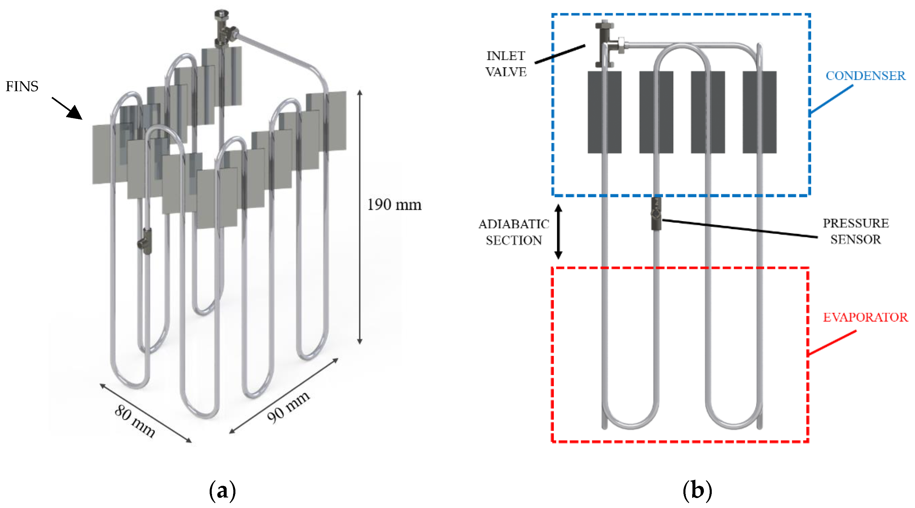
In this study, the PHP being investigated consisted of three main sections: the evaporator, the condenser, and the adiabatic segment, with respective lengths of 9 cm, 7 cm, and 3 cm, as illustrated in
Figure 1. The PHP exhibited a three-dimensional structure with bends on three sides, carefully designed to encase the battery without hindering the assembly process. To construct the device, a stainless-steel tube characterized by inner and outer radii of 0.88 mm and 1.59 mm, respectively, was bent over a total of 11 turns. To prevent flattening of the pipe, a hand tube bender (Swagelok, Solon, Ohio, USA) was used. Stainless-steel pipes were chosen for their accessibility and cost-effectiveness, both essential for practical industrial applications. The pipe was evacuated and then partially filled with HFC-134a. The filling ratios ranging from 20% to 80% to enable the device to function effectively as a pulsating heat pipe [
29], with previous experiments identifying 50% as optimal for our case [
19]. In our study, filling ratios between 40% and 70% demonstrated comparable performance under the input power conditions considered here. Lower ratios, such as 20% and 30%, facilitate quicker device startup but also accelerate progression to the dryout state, posing significant risks for battery applications. Conversely, an 80% filling ratio requires more power for activation, leading it to function longer akin to a thermosyphon, predominantly transferring latent heat from evaporation and condensation rather than combining it with sensible heat through oscillatory movement. The filling ratio (FR) corresponds to the initial volumetric portion of the pulsating heat pipe filled with the working fluid. The fluid volume was calculated based on the liquid density at ambient temperature and the fluid mass, determined by weighing the pulsating heat pipe both with and without the fluid, using a high-precision balance (EG 620 3NM, Kern & Sohn, Balingen, Germany). Initially, the performance of the proposed PHP was assessed independently of the battery within a dedicated experimental setup as detailed in [
19]. This setup consisted of a DC power supply, a wind channel, a fan, and a data acquisition system. A diverse range of boundary conditions and power input values were considered. During these tests, incremental heating inputs were applied to the evaporator, in the interval 1–90 W, using a DC power supply. The heating was achieved through the Joule effect, utilizing an electrical resistance wound around the PHP turns alongside the entire evaporator segment and connected to the power supply.
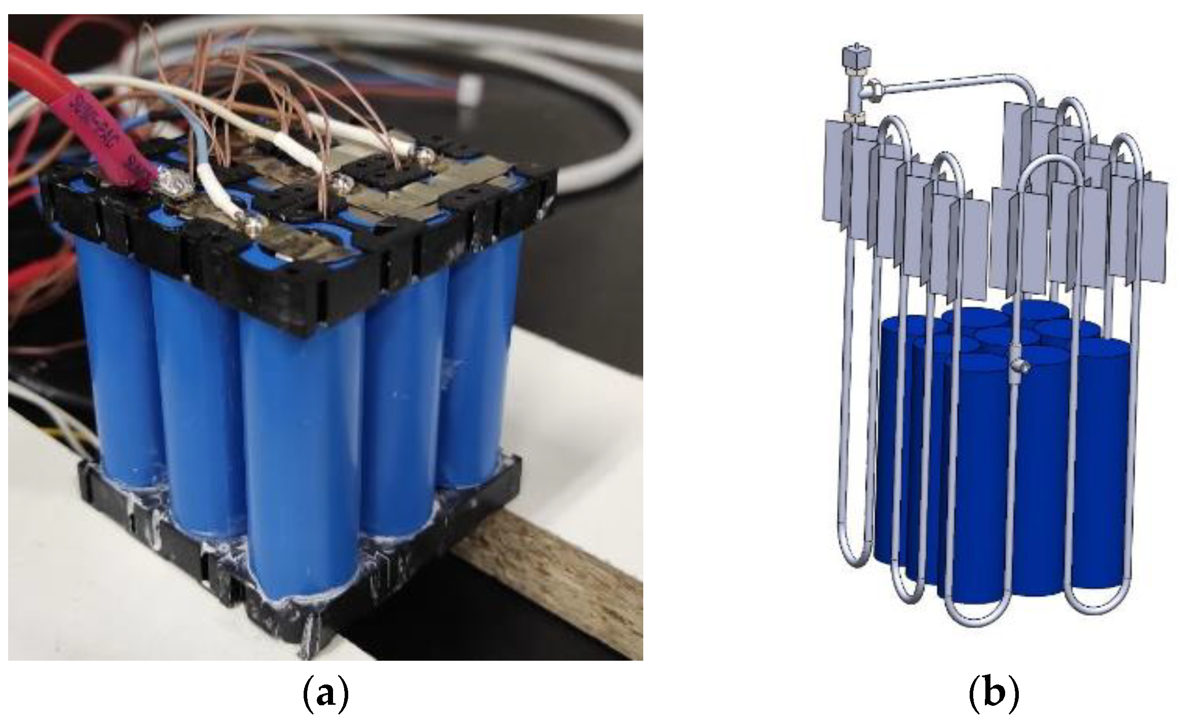
Subsequently, the PHP was integrated into a physical battery pack comprising nine battery cells arranged in a 3P3S configuration, as illustrated in
Figure 2. The battery unit employed in this study is a commercially available LiFePO4 model (18650. EN-ERpower, Monza, Italy). This cylindrical cell measures 65 mm in height, 18 mm in diameter, and weighs 42 g. Its nominal cell potential is 3.2 V, with a maximum voltage of 3.65 V when fully charged. The nominal capacity of the cell is 1.8 Ah, and it can sustain a maximum continuous discharge current of 5.4 A. Within the battery assembly, there exists a pack with a nominal voltage of 9.6 V and a storage capacity amounting to 5.4 Ah. This capacity arises from the configuration involving three cells linked in series and an additional three cells connected in parallel.
To regulate the battery’s charging and discharging, a programmable power supply (RMX-4125, National Instruments, Austin, TX, USA) and DC electronic load (RMX-4005, National Instruments, Austin, Texas) were employed. The electronic load offers precise current control with an accuracy of ±0.1% F.S. within the range of 0–70 A and a resolution of 2 mA. A current transducer was utilized to measure the operational current, with an instrument uncertainty of ±0.02 A within the range of ±85 A. Ambient temperature and relative humidity were monitored, with uncertainties of ±0.6 °C and ±2.5%, respectively. Transducer signals for current and ambient conditions, as well as cell potential, were collected using the NI 6289 data acquisition device (National Instruments, Austin, Texas), which offers a resolution of 0.076 mV in the 0–10 V range, with an uncertainty of ±0.25 mV.
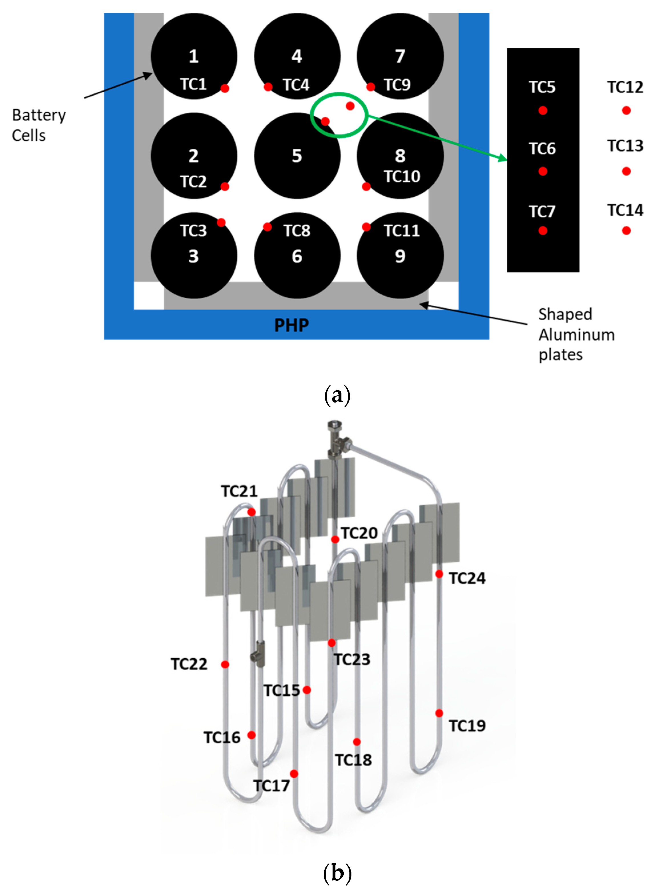
Temperature measurements at various cell surfaces, as well as the evaporator and condenser sections of the PHP, were obtained using T-type thermocouples positioned as shown in
Figure 3. Regarding the battery temperature measurements TC1–TC4 and TC6–TC10 were positioned at half the height of the cells 1–4 and 6–9 to measure the temperature of the cells in the central position where convection is expected to be less effective, while additional sensors were adopted for the central cell (N°5) that is the most critical one regarding overheating. The cell surface temperature was measured by three T-type thermocouples (TC5–TC7) equally spaced along the height of the battery. Other T-type thermocouples (TC12–TC14) were placed in the air between cells 5 and 7 to observe the air temperature during the tests. These sensors were calibrated against an ice point reference to achieve a temperature uncertainty of ±0.05 °C through calibration in a high-precision bath.
3. Results and Discussion
As mentioned earlier, the device underwent initial characterization in a separate test setup [
19]. In the initial trials, a staircase power input ranging from 1 W to 90 W was applied to the evaporator using a wire heater. Initially, the PHP thermal behavior was assessed considering the average thermal resistance (
Req), a metric commonly testified by different scientific works [
29,
30,
31]:
In the formula,
represents the average temperature measured by the thermocouples at the evaporator, while
signifies the average temperature at the condenser (as depicted in
Figure 3b). Specifically, referring to
Figure 3, the average temperature at the evaporator is calculated as the mean of the temperature values measured by thermocouples TC15–TC19, while the average temperature at the condenser is represented by the mean of the values measured by thermocouples TC20–TC24.
Q denotes the electric power input provided to the wire heater. The performance evaluation of the proposed PHP was detailed in [
19], which involved testing under air cooling conditions at the condenser. Three distinct flow conditions were examined: natural convection, forced convection at 1 m/s, and forced convection at 2.5 m/s.
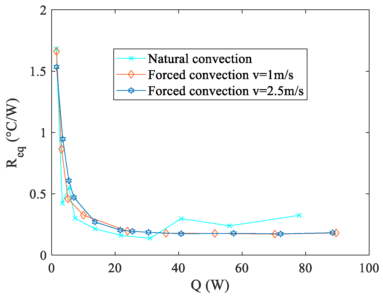
Figure 4 and
Figure 5 illustrate the
Req and
distributions for all arrangements tested, respectively.
Observing
Figure 4 reveals that the two setups employing forced convection at the condenser exhibit superior performance in terms of the
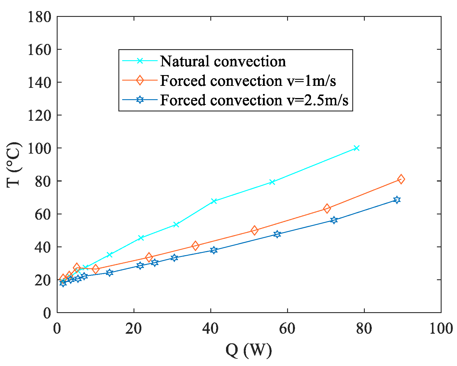
Req. Moreover, also the configuration relying on natural convection displays promising outcomes, showcasing a thermal resistance marginally higher than those observed in the forced convection scenarios within the 40–80 W range. However, it is important to note that this natural convection configuration presents considerably elevated temperature levels at the evaporator, as illustrated in
Figure 5. This characteristic holds significance within the context of the present study, as elucidated in the introductory section. Operating outside the specified temperature range (20–40 °C) significantly accelerates the aging process or may even lead to untimely structural failure. To explore the operational effectiveness of the presented thermal management device under real-world conditions, practical tests were conducted using an authentic battery pack. Three distinct discharge curves, each corresponding to various fully discharging processes, were examined. These curves were generated by maintaining a constant operational current at different magnitudes of C-rates, denoted as 1C, 2C, and 3C as described in the experimental setup section. The selection of these discharge curves as test conditions stems from the fact that Li-ion cells frequently endure demanding operating scenarios during the discharge or charge phase. These discharge curves were chosen as representative conditions to assess the viability of the presented thermal management device. Additionally, in real-world applications, the discharging current of Li-Ion batteries can fluctuate over time. Therefore, it is vital for a BTMS to maintain stable and uniform battery temperatures across various operating conditions. Notably, among the three boundary conditions explored in preliminary tests, the most challenging scenario, i.e., natural convection, was considered for these assessments. All the tests were performed in a conditioned laboratory where the temperature was kept around 20 °C. To prevent malfunctions or potential overheating, the aim of the battery thermal management system is to keep the maximum temperature below 40 °C.
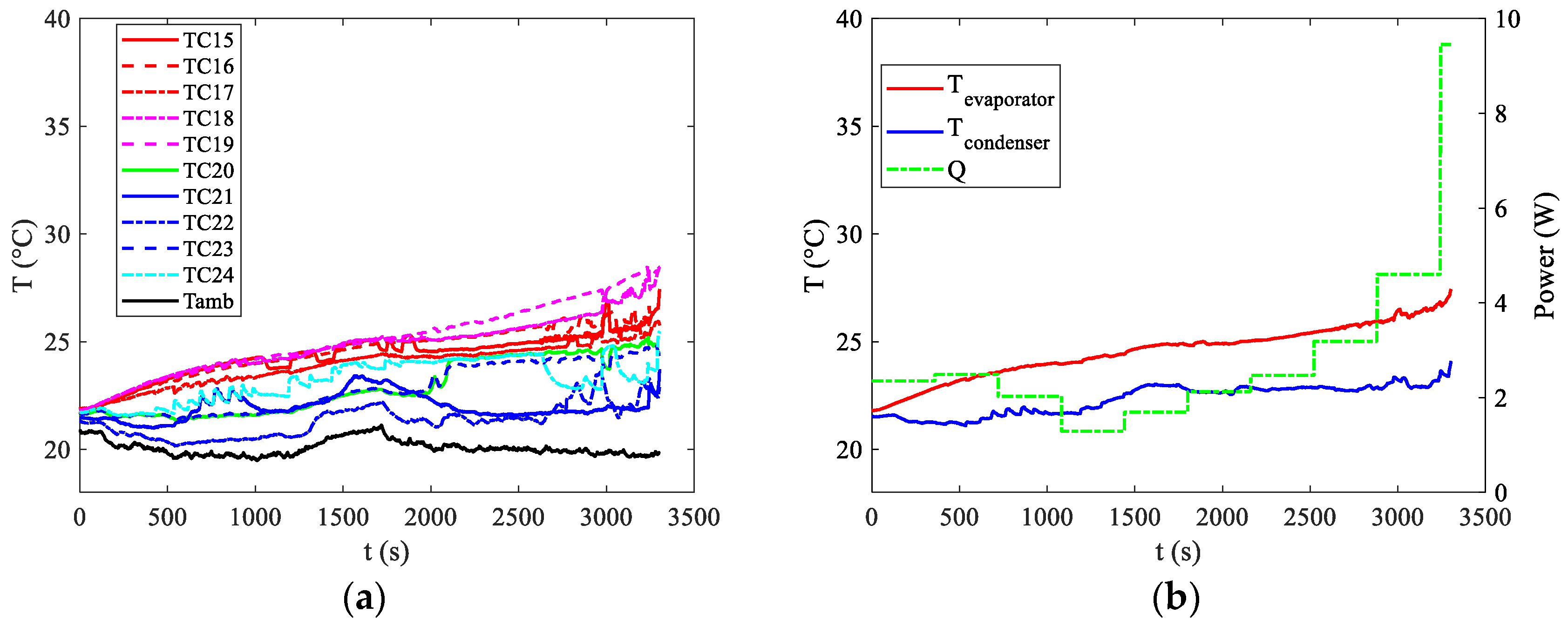
Figure 6a illustrates the temperature distributions recorded by all the thermocouples indicated in
Figure 3b. Additionally,
Figure 6b displays the average temperature readings at both the evaporator and condenser, along with the power supplied by the battery at the evaporator section.
From
Figure 6, it is interesting to notice that the first activation of the PHP device can be seen only in the last part of the curve around 3000 s. The start up of the PHP can be recognised by the appearance of the first oscillations in the device visible from pulsations in the temperature distributions both at the evaporator and at the condenser. For a discharge rate of 1C, the power dissipation is notably low, as depicted in
Figure 6b. The device effectively maintains temperatures below the upper limit, even without operating in oscillating mode for the initial 3000 s. During this period, the device does not strictly operate in pulsating mode nor purely in conductive mode, as observed with an empty device. In a scenario of pure conductive mode, the temperature curve of the evaporator would exhibit a significant upward trend. However, after an initial phase resembling pure conductive mode, that seems to last some hundreds of seconds, the device likely transitions into thermosyphon mode, where buoyancy and gravity forces primarily drive the motion. While heat transfer due to latent heat of evaporation and condensation persists, the pulsating high-frequency oscillations characteristic of the PHP mode are absent, resulting in a smoother temperature distribution at both the evaporator and condenser. This smoothing effect is especially evident in
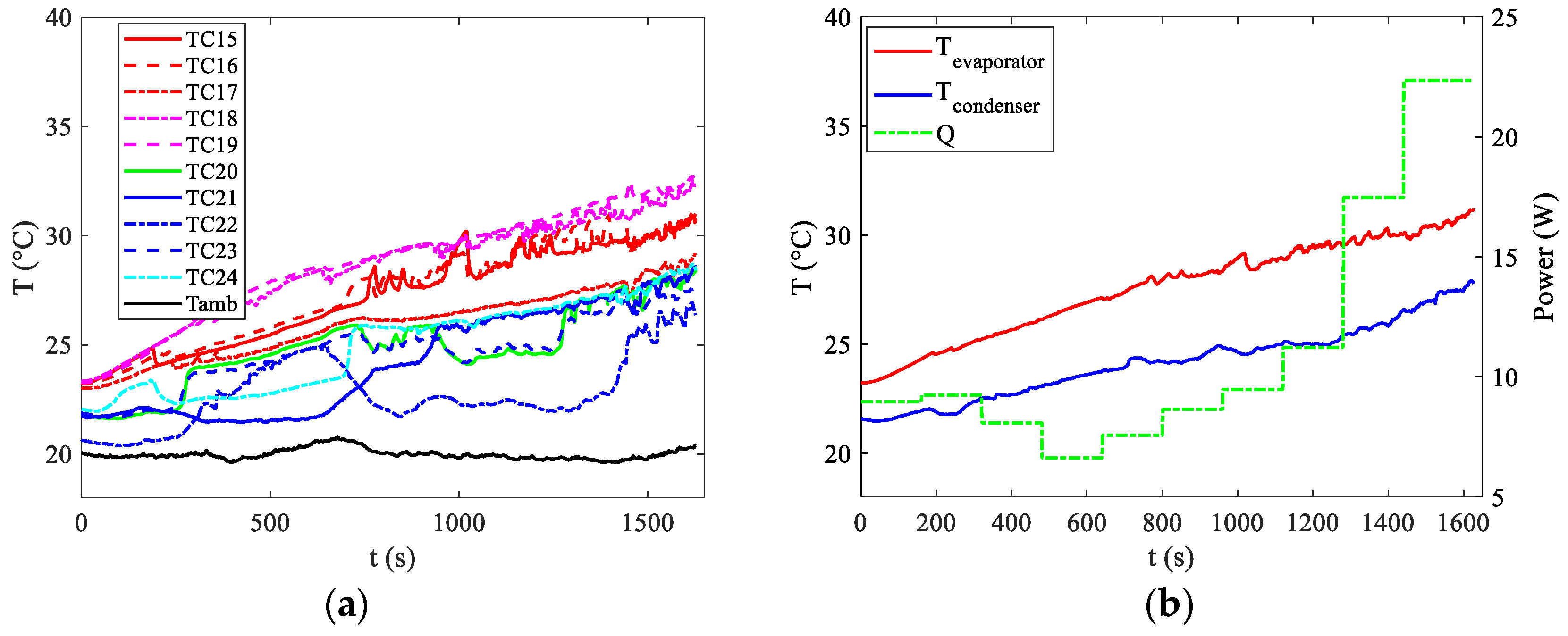
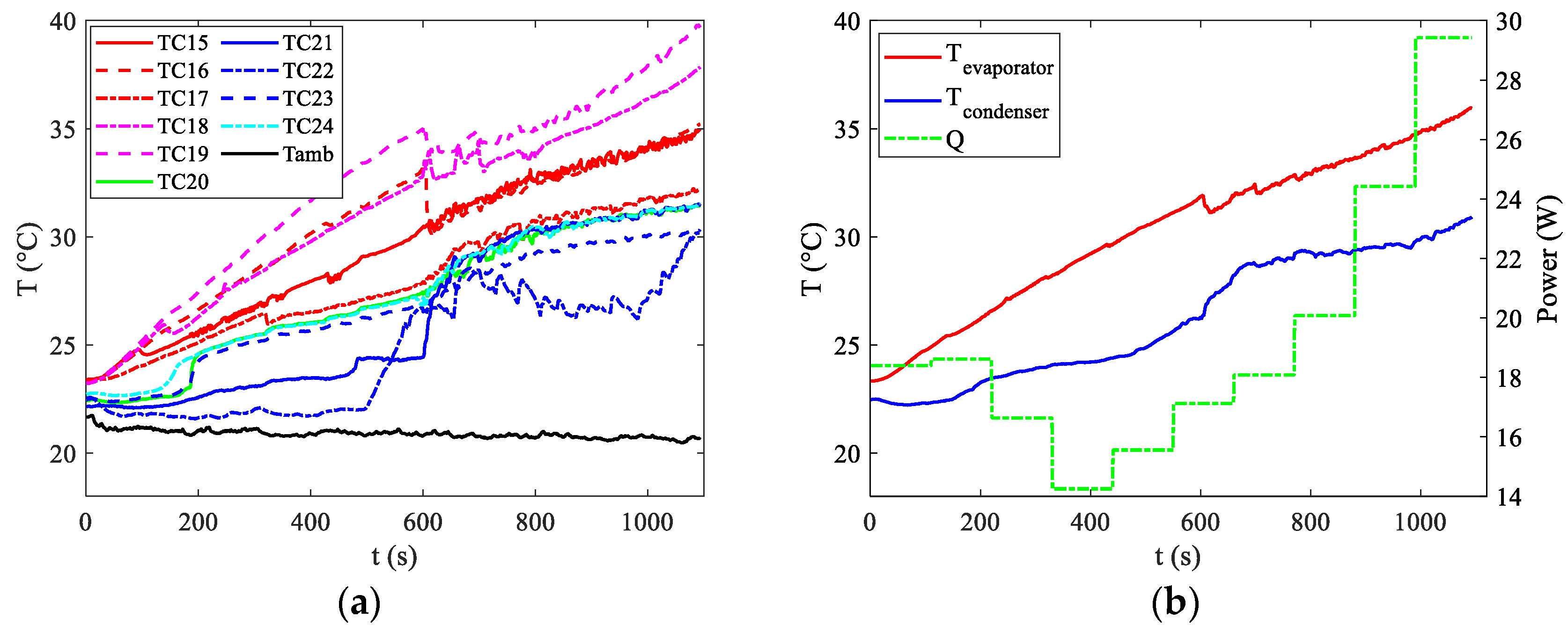
Figure 6b, where average temperature values show a gradual trend until approximately t = 3000 s, when the first oscillations become apparent. Nevertheless, the target of maintaining temperatures below 40 °C is achieved, with the maximum temperature reaching around 28 °C towards the end of the discharge curve. The temperature distributions, along with the average temperatures at the evaporator and condenser and the power supplied by the battery at the evaporator section, are also depicted for discharge rates of 2C and 3C in
Figure 7 and
Figure 8, respectively.
For discharge rates of 2C and 3C, activation occurs earlier, at around 200 s. However, this activation is insufficient to keep temperatures below the upper limit in the 3C case. Towards the end of the discharge curve, temperatures measured by certain thermocouples near the evaporator approach 40 °C, indicating that under slightly less favourable ambient temperatures, the upper limit would likely be exceeded.
The bottleneck in this scenario arises from the minimal convective coefficient among the pipes at the condenser section and the surroundings. Typically, natural convection is characterized by coefficients between 5 and 20 W/m2 °C. To address this problem, it is essential to enhance the heat exchange area. However, this issue does not occur when forced convection is present at the condenser, such as when the car is in motion.
The goal of the presented cooling system is to offer a robust, effective, and completely passive BTMS for all operating settings. Therefore, it is imperative to resolve the chokepoint caused by the minimal coefficient value in natural convection at the condenser section. The device must ensure optimal battery temperature regulation even when forced convection is unavailable, without relying on external power sources. This is particularly crucial during the charging process when the vehicle is stationary, and natural airflow cannot reach the battery without the use of a fan, which would consume additional energy. The results presented so far have focused on the temperature distributions within the PHP device, which, however, only makes contact with the external cells of the battery. These external cells are not the primary concern for the proposed battery thermal management system. It is important to recognize that not all cells within the battery pack exhibit identical behaviour. Referring to the schematic in
Figure 3a, the two most critical cells are Cell N°5, positioned centrally, and Cell N°4, primarily due to the lack of contact with the PHP on one side of the battery. This configuration was necessitated by practical assembly constraints, specifically the need for space to accommodate power supply and measuring cables.
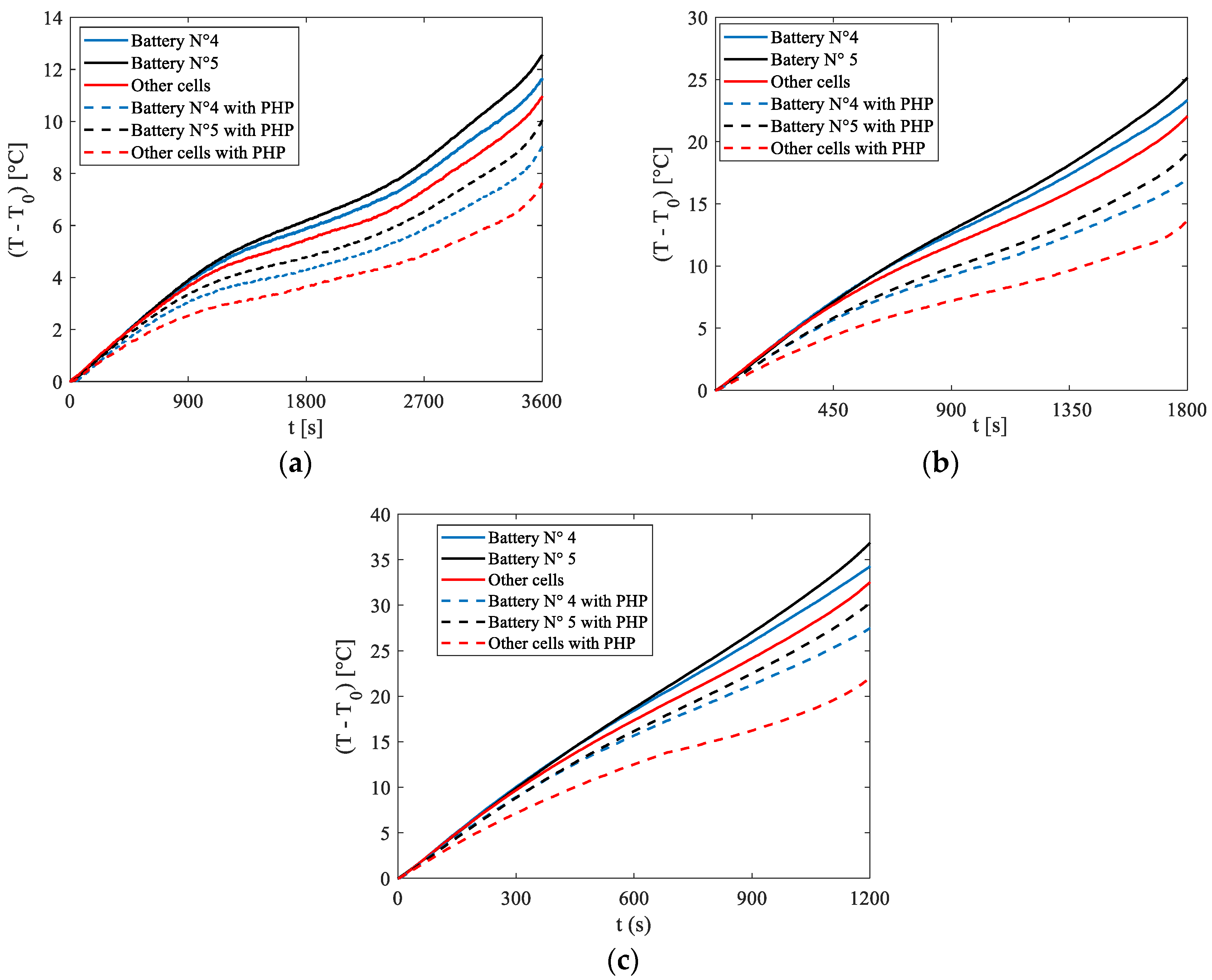
Figure 9 depicts the temperature increase relative to the initial condition (
T0) for Cells N°4 and N°5, alongside the average temperature rise of the remaining cells exhibiting similar behaviour. These temperature variations are shown for discharge rates of 1C, 2C, and 3C, under natural convection conditions.
Additionally,
Figure 9 also shows the same temperatures obtained in the absence of the PHP. A comparison reveals that in all cases and for all cells, the application of the PHP reduced the temperature increase. Particularly notable is the effect observed in cells other than N°4 and N°5, where direct contact with the PHP resulted in tangible benefits. For these cells, the adoption of the PHP led to temperature reductions of 3 °C, 9 °C, and 11 °C for 1C, 2C, and 3C discharge rates, respectively. These results highlight the potential of the proposed BTMS as a promising solution for electrical battery cooling.
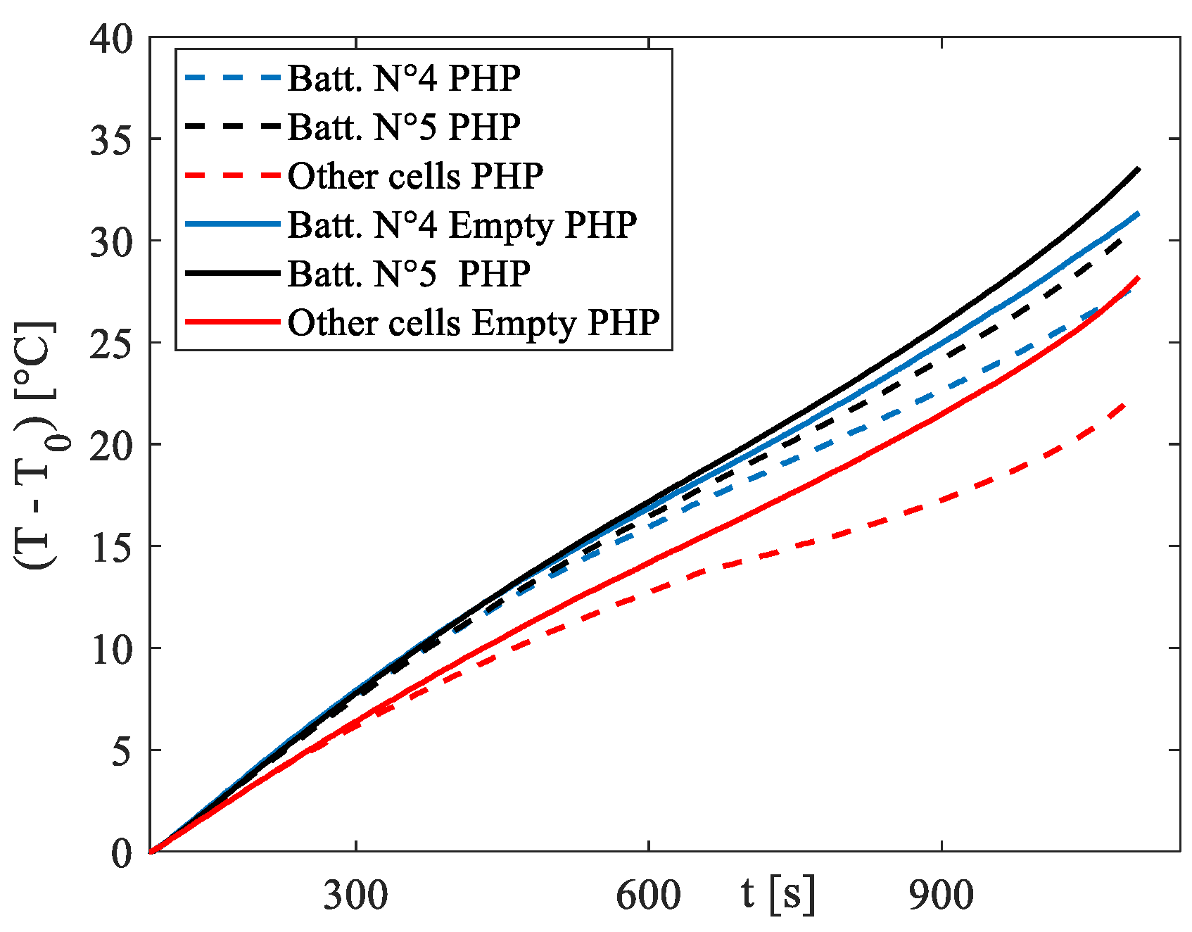
To ascertain whether the contribution of the PHP is indeed due to the latent heat related to evaporation and condensation inside the device, along with the sensible heat resulting from the oscillations that occur upon activation, another set of experiments was conducted using the same setup but with the PHP empty, i.e., without fluid inside. This approach allows for the differentiation of the effective contribution of the two-phase device from the intrinsic fin effect.
Figure 10 presents the results under more rigorous conditions, specifically the 3C discharge rate. It is evident that the difference between the functioning PHP and the empty device is significant, with little disparity between the empty PHP and the absence of the PHP reported in
Figure 9c.
The consistent cooling demonstrated by the proposed system underscores its potential as a robust solution for managing the thermal aspects of electrical batteries. However, there are two main issues that must be addressed in the engineering of the product: firstly, under natural convection, the low heat transfer coefficient values pose a significant challenge in achieving the goal of maintaining the battery temperature within the optimal working range. In this scenario, increasing the surface area of the condenser section by implementing a more efficient and extensive fin battery pack could be a viable solution. Another significant issue pertains to temperature differentials across both the battery pack and individual battery cells, which can significantly impact the long-term performance of the battery system. Substantial temperature variations within the battery pack and at the pack level can result in varying rates of capacity fade and unbalanced voltage distribution within the pack. Therefore, maintaining a small temperature difference is crucial for Li-Ion battery packs, serving as an indicator of an effective battery thermal management system. Regarding the temperature gradient along the single cell, the here-proposed BTMS configuration does not present great problems, with a maximum difference along the central cell of less than 2 °C. On the other side, a difference in the temperature can be an issue with this setup: indeed, as it is possible to see from
Figure 10, a max temperature difference among the cells is around 2.5 °C, 5.5 °C and 9 °C for 1C, 2C and 3C discharging curves, respectively. The significant temperature gradient within the battery pack primarily arises from the diverse cooling environments surrounding various sections of the pack. Cells on three sides of the pack can efficiently transfer heat to the surroundings through the PHP turns. However, the interior regions rely solely on conduction between the batteries to dissipate heat, which imposes limitations on heat dissipation. This limit can be overcome by inserting some turns inside the different rows of cells, as sketched in
Figure 11. The new setup is in the phase of production, and it will be tested in the next months.
