Abstract
In recent years, the State Grid of China has placed significant emphasis on the monitoring of noise in substations, driven by growing environmental concerns. This paper presents a substation noise monitoring system designed based on an end-network-cloud architecture, aiming to acquire and analyze substation noise, and report anomalous noise levels that exceed national standards for substation operation and maintenance. To collect real-time noise data at substations, a self-developed noise acquisition device is developed, enabling precise analysis of acoustic characteristics. Moreover, to subtract the interfering environmental background noise (bird/insect chirping, human voice, etc.) and determine if noise exceedances are originating from substation equipment, an intelligent noise separation algorithm is proposed by leveraging the convolutional time-domain audio separation network (Conv-TasNet), dual-path recurrent neural network (DPRNN), and dual-path transformer network (DPTNet), respectively, and evaluated under various scenarios. Experimental results show that (1) deep-learning-based separation algorithms outperform the traditional spectral subtraction method, where the signal-to-distortion ratio improvement (SDRi) and the scale-invariant signal-to-noise ratio improvement (SI-SNRi) of Conv-TasNet, DPRNN, DPTNet and the traditional spectral subtraction are 12.6 and 11.8, 13.6 and 12.4, 14.2 and 12.9, and 4.6 and 4.1, respectively; (2) DPTNet and DPRNN exhibit superior performance in environment noise separation and substation equipment noise separation, respectively; and (3) 91% of post-separation data maintains sound pressure level deviations within 1 dB, showcasing the effectiveness of the proposed algorithm in separating interfering noises while preserving the accuracy of substation noise sound pressure levels.
1. Introduction
With the acceleration of urbanization and expanding needs of industries, agriculture, and residential areas, urban electricity demand in China has experienced a sharp rise. This surge in demand has resulted in the construction of numerous electric substations in urban areas, including those in close proximity to residential communities [1], leading to growing concerns about the noise pollution stemming from the operation of substation equipment.
To address the impact of excessive noise from substations on residents’ lives, China took action by issuing the Law of the People’s Republic of China on Prevention and Control of Pollution from Environment Noise [2] in December 2021, which mandates that substations are responsible for monitoring industrial noise, maintaining monitoring records, and guaranteeing the authenticity and accuracy of the collected data. Consequently, in the past few years, significant attention has been paid to implementing round-the-clock, real-time monitoring of substation noise levels by the State Grid of China.
The key to substation noise monitoring lies in the precise collection and analysis of the noise generated by the operational equipment within the substations. According to the statistics analysis on measured data of 43 substations in [3], the sound pressure levels of noise emitted by substations are distributed in the range of 45 to 75 dBA. Nevertheless, due to the geographical positioning of substations, the noise captured at the substation boundaries often includes mixed environmental sounds such as continuous bird or insect chirping, sporadic human voices, and other background noise. This mixture of noises can lead to erroneous measurement outcomes and false alarms regarding noise level exceedances. Consequently, it is essential to develop and implement a substation noise monitoring system that not only captures noise data within the substations accurately but also effectively separates equipment-generated noise from environment noise.
1.1. Related Work
A number of research studies and instances of industrial implementation have been conducted on noise monitoring systems and audio separation methods. In the following, a comprehensive review of the existing works will be provided.
1.1.1. Noise Monitoring Systems
Noise monitoring systems have been extensively utilized across different sectors such as transportation, industrial manufacturing and so forth, which can be mainly divided into three categories: (1) sound level meters, (2) noise monitoring systems based on wireless sensor networks (WSNs), and (3) integrated noise monitoring systems that incorporate acoustic event recognition and analysis.
- (1)
- Sound Level MetersSound level meters serve as fundamental tools for general noise measurement tasks, typically handheld devices used for short-term monitoring by individuals. These meters calculate real-time time-weighted, frequency-weighted sound pressure levels, as well as octave and other relevant data. The digital sound level meter is currently the most prevalent option, utilizing a dual-core processor architecture comprising ARM and DSP processors. The DSP processor, renowned for its robust data processing capabilities, handles tasks like time and frequency weighting, as well as octave analysis within the sound signal. Conversely, the ARM processor is dedicated to providing a user-friendly interactive interface, responsible for displaying measurement data and managing stored information.Currently, numerous mature products exist in the market for sound level meters, such as the esteemed HBK 2255 model from Denmark’s Brüel & Kjær company. These meters are distinguished by their portability and user-friendly design, offering convenience for monitoring personnel to perform quick measurements. However, when it comes to systems necessitating prolonged automated monitoring, these devices fall short in meeting the demand for continuous 24-hour surveillance.
- (2)
- Noise Monitoring Systems Based on Wireless Sensor NetworksFor noise monitoring system based on WSNs, they typically comprise a multitude of wireless sensor nodes strategically placed in various locations, which gather real-time noise data and transmit it via wireless communication techniques to a central node for subsequent processing and analysis.Wireless sensor network technology was applied early to environment noise monitoring in [4] by implementing sensor nodes for capturing indoor and outdoor noise data, along with a Matlab-based tool for real-time processing and visualization of this data. This groundbreaking research established the feasibility of wireless sensor networks for real-time data acquisition. Following this, research endeavors gradually shifted towards the development of cost-effective and energy-efficient noise acquisition sensor nodes. Hakala et al. introduced the CiNet platform specifically tailored for monitoring traffic noise using wireless sensor networks in [5]. Furthermore, the Raspberry Pi platform was adopted as the sensing unit in [6], which further integrated cloud storage technology for data processing.The studies above primarily concentrated on addressing critical technical aspects within wireless sensor networks, such as microcontroller-based data processing technology and wireless network communication technology, leading to a reduction in overall system costs and facilitating their widespread adoption in noise monitoring applications. However, it is worth noting that these systems typically compute relevant monitoring parameters, where the interference of background noise was largely ignored.
- (3)
- Integrated Noise Monitoring Systems with Acoustic Event Recognition and AnalysisIn the evolution of noise monitoring systems, there has been a shift towards exploring advanced analytical techniques beyond the traditional continuous measurement of parameters such as sound pressure level and octave analysis. An increasing emphasis has been placed on leveraging collected noise data to provide valuable insights for optimizing system operation and enhancing maintenance practices. One prominent area of focus lies in acoustic event classification, where diverse methodologies, including machine learning [7] and deep learning [8,9], have been employed. These approaches have proven instrumental in a variety of application scenarios, encompassing outdoor public safety monitoring [7,8,10], traffic congestion monitoring [11], and automatic fault diagnosis [9].
1.1.2. Audio Separation Methods
As mentioned above, a major challenge in substation noise monitoring is how to separate the equipment noise from the mixed environment noise. In this section, a thorough literature review on audio separation methods will be presented. Specifically, the existing works on the separation of multiple signals from mixed audio signals can be classified into mono-channel audio separation [12,13,14] and multi-channel audio separation [15,16,17], depending on the number of sensors utilized for audio collection. These methods are typically categorized as: signal-processing-based, statistical-model-based, and deep-learning-based approaches.
- (1)
- Signal-Processing-based Substation Noise Separation MethodsSignal processing-based substation noise separation methods typically involved analyzing the time and frequency domain characteristics of different sound source signals to design various noise separation techniques. Ref. [12] proposed a method for audible noise separation in Ultra High Voltage Alternating Current substations by utilizing wavelet packet analysis combined with spectral subtraction-based speech enhancement techniques to filter out environment noise. Ref. [13] proposed an algorithm based on the maximal overlap discrete wavelet transform to denoise partial discharge signals originating from defects in power cables contaminated with various levels of noise.
- (2)
- Statistical-Model-based Substation Noise Separation MethodsStatistical model-based substation noise separation methods usually use statistical principles to process mixed noise signals and differentiate between various noise sources based on the statistical characteristics of the noise signals. Specifically, a method based on Sparse Component Analysis-Variational Mode Decomposition (SCA-VMD) was proposed in [14] for separating and denoising transformer operational sound signals. In 2022, Ref. [18] proposed a blind source separation technique for transformer acoustic signals based on SCA, involving a transformation from the time domain to the time-frequency domain and the extraction of single source points in the time-frequency plane through the identification of phase angle discrepancies in the time-frequency points. Ref. [17] presented a noise separation method employing the phase conjugation technique to segregate intrinsic noise signals from different transformers, which involves reconstructing sound source information using phase conjugation and employing the equivalent point source method to derive the intrinsic noise signal of the sound source.
- (3)
- Deep-Learning-Based Substation Noise Processing MethodsThe rapid advancements in deep learning have ushered in a new era for substation noise processing in recent years [19,20,21,22,23], with a notable emphasis placed on anomaly detection of substation equipment’s operational status through voiceprint recognition. In the realm of audio separation, the majority of existing studies have focused on isolating multiple human voices in speech signals. Various models, such as deep clustering [24], Wave-U-Net [25], Conv-TasNet [26], Sepformer [27], and Mossformer [28], have been proposed and trained on extensive datasets comprising mixed speech signals and corresponding clean sources. These models have demonstrated significant potential in achieving real-time, accurate speech separation with minimal latency compared to traditional methods. Hence, it is of great interest to explore the applicability of deep learning models for addressing substation noise separation challenges.
1.2. Contributions and Main Results
This paper introduces the design, implementation and evaluation of an intelligent substation noise monitoring system for the State Grid of China. The contributions and main results of this work are summarized as follows:
- A substation noise monitoring system structured with a terminal-network-cloud layered architecture is proposed, which allows for (1) end devices to gather real-time substation noise data and report suspected exceedance events via 4G wireless communications and (2) the cloud center to store, analyze, and visualize anomalous noise data, offering precise substation noise exceedance alarms for operational and maintenance purposes.
- The design and implementation of a self-developed noise acquisition device that consists of a microphone, ARM, and DSP components are carried out. This device enables real-time collection of noise data within the substation boundaries, providing the necessary hardware foundation for noise data analysis. The device accurately evaluates acoustic characteristics of noise data, such as time-domain weighting, frequency-domain weighting, and octave analysis. Hardware experiments demonstrate that the noise monitoring device’s performance satisfies the criteria of the international standards IEC61672 [29] for Class 1 sound level meters.
- Three intelligent substation noise separation algorithms based on Conv-TasNet, DPRNN, and DPRNet were proposed to effectively separate equipment noise and environment noise within substations so as to precisely calculate the sound level of in-station equipment noise. These algorithms are trained using a custom dataset of substation noise, which includes mixed audio samples of substation equipment noise (transformer and corona) and environment noise (insect chirping, bird chirping, and human voice), and evaluated across various scenarios. Experimental results show that (1) the deep-learning-based separation algorithms outperform the traditional spectral subtraction method significantly in terms of signal-to-distortion ratio improvement (SDRi) and scale-invariant signal-to-noise ratio improvement (SI-SNRi), where Conv-TasNet, DPRNN, DPTNet and spectral subtraction achieve SDRi and SI-SNRi of 12.6 and 11.8, 13.6 and 12.4, 14.2 and 12.9, and 4.6 and 4.1, respectively; (2) among these, the DPTNet-based noise separation algorithm demonstrates the highest; (3) approximately 91% of station noise shows a sound pressure level difference between pre-separation and post-separation within 1 dB, indicating that the proposed algorithm effectively eliminates environment noise while maintaining the accuracy of the equipment noise’s sound pressure level, which further supports reliable identification of equipment noise exceedances.
1.3. Outline
The remainder of this paper is organized as follows. The overall design and system architecture of a substation noise monitoring system is introduced in Section 2. The self-developed noise acquisition device is presented in Section 3. The deep-learning-based intelligent substation noise separation algorithms are introduced and evaluated in Section 4, based on which, the integrated end-to-end substation noise monitoring is demonstrated in Section 5. Finally, concluding remarks are summarized in Section 6.
2. Design of a Substation Noise Monitoring System
In this section, the problem description of the noise monitoring system is introduced first, followed by a description of its overall system architecture and key components.
2.1. Problem of Interest
Consider a typical scenario of a substation in a geographical area, as shown in Figure 1, where various electrical equipment, such as transformers and reactors, are operating and producing noise in the substation. Due to the diverse locations of National Grid substations, ranging from urban to mountainous areas, it is imperative to monitor the noise levels in these substations to prevent potential noise pollution. Therefore, the goal of the proposed substation noise monitoring system for National Grid is two-fold: (1) To continuously collect noise data at the substation boundaries and promptly detect whether the noise levels exceed the designated pollution threshold in real-time; and (2) to further investigate and determine the root cause of the noise pollution, identifying the specific type of equipment responsible for facilitating efficient operation and maintenance procedures.
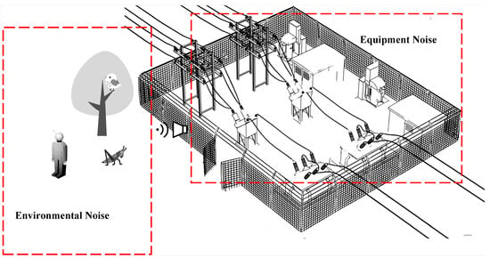
Figure 1.
Graphic illustration of substation noise monitoring system with mixed equipment noise and environment noise.
2.2. Overall System Architecture
The overall architecture of the proposed substation noise monitoring system is illustrated in Figure 2, which adopts a terminal-network-cloud layered structure and consists of two main components: noise acquisition devices at the terminal layer and noise analysis and data visualization at the cloud layer, and will be introduced in detail in the following.
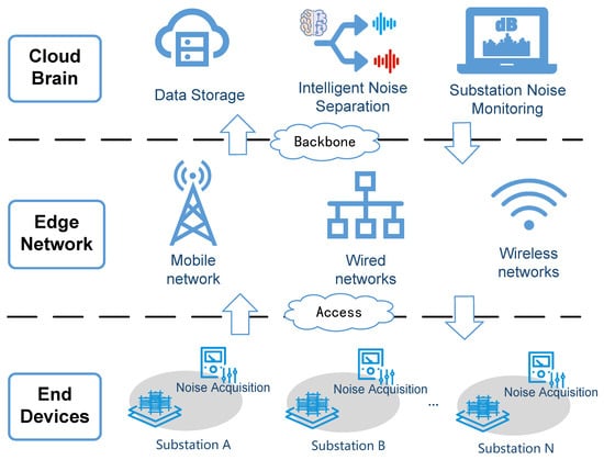
Figure 2.
Overall architecture of substation noise monitoring system.
2.2.1. End: Noise Acquisition Devices
Considering that the proposed system requires continuous monitoring of noise levels in all substations, it is necessary to deploy noise acquisition devices at the boundary of each substation. These devices utilize sound collection sensors to collect real-time sound signals. To determine if the noise level has exceeded a predefined threshold, the devices have two options: processing and analyzing the sound signals on-site, or directly transmitting the signals to the cloud data center without any processing.
In the proposed system, an on-site processing and analysis approach is applied to avoid unnecessary data transmissions and communication delays. That is, the gathered sound data undergo processing to calculate various parameters such as different frequency-weightings sound pressure levels, time-weighed sound pressure levels, and octave. The device then determines if there are any anomalies based on these calculations. If an anomaly is detected, the calculated results and one-minute audio data will be transmitted to the cloud data center for record keeping and further analysis.
2.2.2. Cloud: Noise Analysis and Data Visualization
For the cloud center, any anomalous noise data sent from all substations in the system will be initially recorded and stored in the noise monitoring database. It is important to note that although those noise exceeds the environmental protection authorities’ stipulated threshold, the exact cause of the excessive noise remains unclear. It could be attributed to either environment noise or electrical equipment noise. Therefore, it is essential to conduct an in-depth analysis of these anomalous noise samples at the cloud center to ascertain whether the equipment within the substations is accountable for the noise pollution.
In this paper, deep learning methods will be proposed to effectively separate electrical equipment noise from environmental noise. This enables us to provide more accurate noise monitoring and enhanced fault warning capabilities. Additionally, in order to present the noise monitoring results in a more vivid manner, the proposed system will also support results shown via a monitoring management platform, enhancing the ability to visualize and interpret the monitored noise data.
In the following sections, the implementation of a self-developed noise collection device at the terminal layer and the substation noise separation algorithms at the cloud layer will be introduced, respectively.
3. Self-Developed Noise Acquisition Device
In the proposed substation noise monitoring system, a cutting-edge noise acquisition device is designed and developed for noise collection at the boundary of substations. In this section, the hardware design and embedded software of the device are introduced, and a series of experiments are conducted to evaluate the device’s performance.
3.1. Hardware Design
The whole noise monitoring system needs real-time data acquisition and processing during the operation of the substation. Therefore, the design of the noise monitoring system needs to meet specific requirements, which are summarized as follows:
- Precision in Noise Measurement: the device should possess the capability to accurately measure the noise levels produced by the substation and conduct detailed analysis and evaluation of noise across various frequency ranges.
- Stability and Robustness: Given the potential impact of the substation’s electromagnetic environment, as well as external factors like wind and rain, the device must incorporate appropriate protective measures to mitigate these influences. Moreover, as noise monitoring is an ongoing task, the system should ensure continuous data collection, analysis, and transmission without interruptions.
- Real-Time Data Processing and Transmission: During noise acquisition, there is a need for real-time calculation of metrics such as time-weighted sound pressure level, frequency-weighted sound pressure level, and octave analysis. This necessitates real-time processing and transmission of data, by leveraging the high-speed computing capabilities of the DSP chip for real-time calculations and utilizing 4G communication for transmitting these calculated characteristics to a background database.
The hardware design and workflow of the self-developed noise acquisition device is illustrated in Figure 3, which is mainly composed of a microphone, a meteorological sensor, signal conditioning module, acquisition module, Arm-based processor and DSP-based processor. The operational process is summarized as follows: initially, in accordance with the planned layout of measurement points, the necessary hardware devices are arranged for each designated position within the substation. Once the monitoring task commences, the gathered signals undergo adjustments via the signal conditioning circuit before proceeding to the A/D converter module for data sampling. Subsequently, the data are stored in the NAND Flash module and facilitates data exchange with the DSP through the dual-port RAM. The specific equipment, models, and characteristics used in the proposed noise acquisition device are summarized in Table 1.

Figure 3.
Hardware design of the self-developed noise acquisition device.

Table 1.
Device, models, and key features adopted in the proposed noise acquisition device.
3.2. Embedded Software Design
The software design for embedded systems is centered on utilizing STM32 as the core control software and DSP as the core computing unit software, as depicted in Figure 4. The control unit software primarily comprises three main components: modulus conversion, 4G communication, and data exchange modules. The modulus conversion module employs STM32’s onboard general-purpose timer interrupt to sample each channel at regular intervals, ensuring precise data acquisition. For 4G communication, the system is based on MQTT bidirectional communication. The data exchange module facilitates inter-chip data exchange through dual-port RAM. On the other hand, the computing unit software primarily includes two main components: data analysis and data exchange modules. The data analysis module encompasses functions such as time-weighted sound pressure level, frequency-weighted sound pressure level, and octave analysis. The data exchange module is responsible for transferring the computed results to the Arm processor.

Figure 4.
Embedded software design of the self-developed noise acquisition device.
3.3. Sound Level Algorithm Implementation
This subsection introduces the design of the main functions of data analysis, including frequency weighting design, time weighting design, and octave analysis design.
3.3.1. Frequency Weighting Design
Frequency weighting is primarily designed to simulate the auditory perceptual properties of the human ear for sounds of different frequencies. According to Equations (E.1) and (E.6) in the international standard IEC 61672 [29] for common frequency weighting networks, the digital filter formula of C and A frequency weighting in the proposed system can be written as
and
respectively, with the sampling rate of 48,000 Hz and converting the frequency to its digital domain frequency using the bilinear transformation method. After obtaining the corresponding coefficients of the digital filters, the frequency weighting can be implemented in the DSP using the direct Type I IIR library officially provided by ARM.
3.3.2. Time Weighting Design
Time weighting is primarily designed to simulate the time-domain response characteristics of the human ear to noise signals. The international standard IEC 61672 [29] specifies several commonly used time weighting features, with the fast and slow detector characteristics. Specifically, the fast time weighting characteristic has a time constant of 125 ms, enabling it to capture sound signals that change relatively quickly. On the other hand, the slow time weighting characteristic has a time constant of 1 s, allowing for a more gradual response. This reflects the average characteristics of the signal over time. The equation for time weighting is discretized as follows:
where n, and denote the ordinal number of the discrete-time signal, the minimum sampling interval and time constant, respectively. denote the time weighting sound pressure corresponding to different time constants under A-frequency domain weighting.
3.3.3. Octave Analysis Design
Octave analysis is a method of dividing the frequency spectrum of audible noise (20 Hz~20,000 Hz) into a number of frequency bands with different bandwidths, and calculating the sound pressure level in each band one by one. In this paper, octave analysis is implemented in measuring instruments through two methods: frequency domain analysis and time domain analysis. For the frequency domain analysis, the Fast Fourier Transform (FFT) is utilized to convert the energy calculation of discrete time-domain signals to the frequency domain. However, due to the single resolution of FFT, the number of FFT spectral lines at lower octaves is limited, resulting in a lower level of accuracy in analysis. For the time domain analysis, the MATLAB R2021b Signal Processing Toolbox is employed to design a bandpass filter based on the sampling rate and center frequency of each octave. The designed curves representing the amplitude–frequency response are presented in Figure 5.
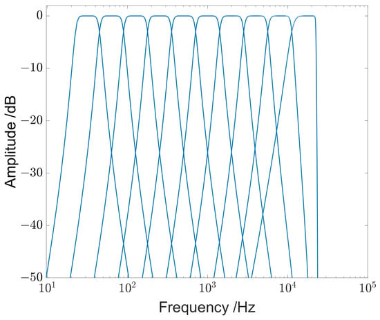
Figure 5.
Amplitude versus frequency with the octave analysis.
3.4. Experimental Results and Discussions
To assess the overall performance of the noise monitoring system, a test platform is constructed as illustrated in Figure 6. The test environment consists of three main components: the sound source, the noise monitoring device, and the web display platform. The sound source comprises a computer, a signal generator, and a dodecahedral sphere sound source. The computer software controls the signal generator to generate diverse signals with varying frequencies and intensities. These signals are then transmitted to the sphere sound source, which uniformly amplifies and disperses the sound to ensure consistent intensity across different directions and distances. The noise monitoring device captures real-time sound signals from the sphere source, converts them into digital signals, and conducts frequency-weighted, time-weighted SPL, and octave analysis calculations in real-time. The results are then transmitted to the backend database via a 4G network and illustrated via the web display platform.
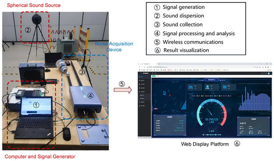
Figure 6.
Test platform of the noise monitoring system.
The noise collection device must adhere to the specifications outlined in the international standard IEC 61672 [29] for Class 1 sound level meters. In this paper, the accuracy performance of the self-developed device is evaluated on frequency weighting, time weighting, and octave analysis in an anechoic chamber.
3.4.1. Frequency Weighting Test
For the frequency weighting assessments of the noise monitoring devices, the primary focus is on ensuring that the measured frequency-weighted sound pressure levels fall within the prescribed range specified in the standard, i.e., from 20 Hz to 20 kHz. Due to the impracticality of individually testing all frequency points, the standard defines 34 nominal frequency test points along with an allowable error range of 1 level sound level meter. In this paper, the frequency and intensity of the sound emitted by the signal generator are controlled according to standard requirements using software. The procedural steps are outlined as follows:
- Step 1: Calibration of the noise monitoring device involves initiating a calibration command on the web display platform. This command triggers the device’s pulse generation circuit to emit an electrical signal at 1 kHz and a 94 dB sound pressure level. Subsequently, the monitoring device automatically adjusts its parameters upon receiving the signal, completing the calibration process.
- Step 2: Setting the sound frequency involves the software-controlled signal generator producing the designated signal frequency for emission by the sound source. Each sound generation cycle lasts for 20 s.
- Step 3: Recording the frequency weighting necessitates noting the frequency-weighted sound pressure level values once the readings have stabilized, accounting for any potential communication delay between the noise monitoring device and the web display platform.
The difference curves between A-frequency weighting and Z frequency weighting are depicted in Figure 7. It can be clearly seen from the curves that the A-frequency weighting test results fall within the acceptable tolerance range, satisfying the requirements for a Class 1 sound level meter.
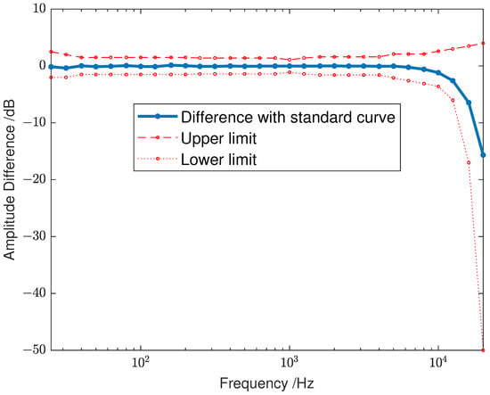
Figure 7.
Amplitude difference versus frequency of the self-developed device for frequency weighting.
3.4.2. Time Weighting Test
The primary focus of time weighting tests is to evaluate whether the sound pressure level change rate aligns with the specified requirements. The standard mandates measuring the rate of sound pressure level change by abruptly terminating a 4 kHz continuous sine waveform produced by a signal generator. For F time weighting, the decay rate should fall within the range of 31.0 dB/s to 38.5 dB/s, while for S time weighting, it should be between 3.6 dB/s and 5.1 dB/s.
The time weighting of the noise monitoring device is evaluated, and the attenuation curve is shown in Figure 8. The calculated decay rate for time weighting F was determined to be 34.37 dB/s, while for time weighting S, it was 4.35 dB/s. Both rates meet the criteria specified in the national standard.
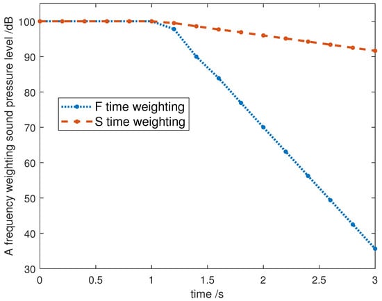
Figure 8.
A frequency weighting sound pressure level versus time for F time weighting and S time weighting, respectively.
3.4.3. Octave Analysis Test
The octave analysis test focuses on octave filters, with GB/T 3241-2010 [30] specifying ten center frequencies for octave filters as follows:
.
Furthermore, the standard delineates the upper and lower tolerance limits for the relative levels of octave filters. In this section, the 1/1 octave filters are extensively evaluated under the 10 filter banks. Figure 9 shows the upper and lower tolerance limits of the standard one-level filter and the amplitude–frequency response of the filter designed in this paper. It can be observed that the designed filters successfully meet the specified requirements.
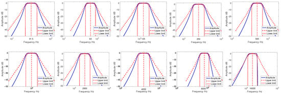
Figure 9.
Amplitude–frequency response characteristics of octave filters with ten center frequencies {31.5, 63, 125, 250, 500, 1000, 2000, 4000, 8000, 16,000}.
4. Deep-Learning-Based Substation Noise Separation Algorithm
This section delves into a pivotal component of the noise monitoring system: the algorithm for separating noise in substations. Firstly, a preliminary analysis on the spectrum characteristics of the typical noise found in substations is presented. Based on that, a noise separation methodology is introduced, employing several deep-learning-based algorithms. The section further encompasses comprehensive performance evaluations and discussions across a range of experimental scenarios to assess the efficacy of these noise separation algorithms.
4.1. Preliminary Analysis
In the following, the spectrum characteristics of distinct types of noise encountered in substations will be analyzed, including internal equipment noise within the substations and interfering environment noise surrounding them, respectively.
Equipment noise in substations mainly consists of transformer noise, reactor noise and corona noise. Data of transformer and reactor equipment noise in real-world substations are gathered, as shown in Figure 10a,b. Corona discharges typically stem from charged structures within substations, the noise data collection of which is severely influenced by the surrounding noise from transformers and reactors. As a result, corona noise is collected through laboratory simulations of corona discharge generation, as illustrated in Figure 10c.

Figure 10.
Substation equipment noise acquisition scenarios.
By analyzing the time-frequency diagrams of various types of equipment, illustrated in Figure 11, the main characteristics of different noise signals are identified. In particular, transformer noise exhibits a smooth profile, with its primary spectrum centered around 100 Hz and extending to its octave, predominantly within the 1000 Hz range. In comparison, reactor noise also presents a smooth distribution with its main spectrum focused at 100 Hz and its octave, where the 100 Hz fundamental frequency noise component is more pronounced than in the transformer noise. As for corona noise, its energy is evenly dispersed across the 20 kHz range, with 100 Hz and 200 Hz standing out slightly above other frequency bands. The frequency ranges and distinctive features of various equipment noise types in substations are summarized in Table 2.

Figure 11.
Time-frequency diagram of equipment noise in substations.

Table 2.
Frequency characteristics of equipment noise.
After analyzing the noise data collected from operational substations, the principal sources of environmental noise in the vicinity of substations are identified and classified into three main categories: insect chirping, bird chirping, and human voices. As depicted in Figure 12a,b, statistical analyses are conducted on the collected environmental noise dataset, based on which the approximate frequency range for each type of noise can be obtained, e.g., the frequency of insect chirping and bird chirping typically falls within the range of 2–8 kHz and 1–6 kHz, respectively. Human voices, originating from substation staff or workers speaking in close proximity to the sound recording device, exhibit frequencies ranging from 0.25 to 8 kHz, as illustrated in Figure 12c. Table 3 summarizes the frequency ranges of the environment noise surrounding the substation, which collaborate with the findings in [31,32,33].

Figure 12.
Time-frequency diagram of different types of environment noise around the substations.

Table 3.
Frequency distribution of background noise.
Remark 1.
The analysis reveals the intricate and partially overlapping spectrum of noise both within the substation and its surrounding environment. This complexity poses a challenge for traditional filtering methods to effectively differentiate between these sources. Therefore, the application of deep learning techniques is advocated to tackle this issue.
4.2. Noise Separation Process Overview
To accurately separate equipment noise and environment noise so as to effectively monitor the substation noise pollution, a two-step noise separation process is devised, as outlined in Figure 13. Similar to the noise collected in practical scenarios, the model’s input comprises a mixture of transformer noise, reactor noise, corona noise, and environment noise. In the first step, a deep learning model is implemented to separate the environment noise and substation equipment noise, and then determine whether the station noise exceeds the standard or not. If it exceeds the limit, then further separation of the station noise is required. The second step is to separate different substation equipment noise. Since transformer noise and reactor noise are relatively similar, they are considered as the same class of noise in this paper. By doing so, it can further be determined which kind of equipment’s noise exceeds the standard.
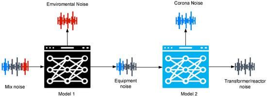
Figure 13.
Graphic illustration of the two-step noise separation process.
4.3. Deep-Learning-Based Substation Noise Separation Algorithm
There exist a large number of deep-learning-based audio separation algorithms. In this paper, according to the properties and requirement of the substation noise separation problem, three representative algorithms are selected and implemented, based on which a thorough comparative study is further conducted.
- Conv-TasNet: Conv-TasNet [26] is a speech separation model leveraging an end-to-end convolutional neural network (CNN) architecture, designed to decompose mixed audio signals into individual sources. In the realm of substation noise separation, CNN’s strength lies in its capability to capture localized features, such as transient bird noises. Moreover, the CNN-based method necessitates less training data, which is particularly advantageous in our case where equipment noise data are often limited. With a compact model size and reduced latency, Conv-TasNet is considered a suitable option for both offline and real-time substation noise separation operations.
- DPRNN: DPRNN [34] further introduces RNN layers in deep structures, facilitating the modeling of exceptionally lengthy sequences. Therefore, DPRNN is considered to analyze the advantage of RNNs in handling extended noises.
- DPTNet: DPTNet [35] is a sophisticated network tailored for end-to-end speech separation, leveraging an enhanced transformer architecture for precise context-aware modeling of speech sequences. It has been widely observed that transformers offer the advantage of employing a self-attention mechanism to effectively capture dependencies across varied positions within the sequence, thereby enhancing separation performance. However, it is important to note that transformer-based models typically mandate substantial volumes of training data and entail longer training time.
4.3.1. Conv-TasNet
The architecture of Conv-TasNet consists of three core components: the encoder, the separation network, and the decoder. The encoder consists of 1-D convolutional blocks (1-D Conv) connected with a ReLU activation layer to extract sound signal features. These blocks operate to convert brief segments of mixed waveforms into corresponding representations within the intermediate feature space. To further refine the separation process, Conv-TasNet employs a Temporal Convolutional Network (TCN) as the separator, responsible for estimating masks for each source at every time step. Lastly, a one-dimensional convolutional module acts as the decoder, reconstructing the source waveforms through the transformation of encoded features as delineated by the TCN.
4.3.2. DPRNN
DPRNN is a network designed to organize RNN layers in deep structures for modeling extremely long sequences, overcoming the limitations of traditional RNN networks in effectively modeling very long speech sequences. The encoder and decoder structure of DPRNN is the same as Conv-TasNet. The main difference is that DPRNN organizes DPRNN blocks as a two-path recurrent neural network in a deep structure instead of the TCN. Each DPRNN block consists of two RNNs with recurrent connections in different dimensions. Bidirectional RNNs within the block are first applied to handle local information. Subsequently, inter-block RNNs are employed to capture global dependencies within the blocks.
4.3.3. DPTNet
DPTNet introduces a transformer structure based on DPRNN, which enables direct context-aware modeling of speech sequences. The encoder and decoder structure of DPTNet is the same as Conv-TasNet. The standout feature of DPTNet lies in its separator component, where a Dual-Path Transformer Network is employed to construct masks for each source. This network introduces an improved transformer to facilitate interconnections between different segments of the input sequence, which empowers it to effectively model speech sequences with direct context-awareness. Additionally, the Scaled Dot-Product Attention mechanism is incorporated to establish correlations between different segments of long-duration speech signals.
4.4. Dataset Construction and Model Training
In this section, the performance of the proposed noise separation algorithms is evaluated in substation noise monitoring system. A new dataset of substation noise monitoring is established, and the training and test results of Conv-TasNet, DPRNN, and DPTNet are presented under different experiment scenarios.
4.4.1. Dataset and Preprocessing
To effectively train a model capable of distinguishing noise from substation equipment and environment noise, preprocessing the raw data is essential to transform it into a format suitable for deep learning model training. The raw data collected are presented in Table 4. Given the substantial variations in data collection methods, durations, and sampling rates across different noise sources in the original dataset, data preprocessing is conducted to construct a unified mixed dataset.

Table 4.
Original data in the dataset.
The preprocessing steps are outlined as follows: Initially, the collected audio data are inputted individually. Audio samples with a duration of less than 3 s are automatically excluded from the dataset. Subsequently, the audio is evaluated to determine if it is single-channel data; if not, the data from the first channel are extracted for further processing. Following this, all audio samples are resampled to a uniform sampling rate of 48,000 Hz and then normalized to ensure that the values fall within the range of −1 to 1. Ultimately, the resampled and normalized audio segments are stored, paving the way for dataset construction.
The dataset construction process involves several steps. First of all, an audio sample is randomly chosen from both the equipment noise and environment noise datasets, ensuring that the selected paths for the two audio samples are distinct to avoid duplication. Subsequently, a random signal-to-noise ratio (SNR) between −5 and 5 is established. The original audio data are then scaled at various ratios within this range to produce scaled audio samples. These scaled audio samples are combined to create mixed audio. Finally, the scaled versions of the two original audio samples and the mixed audio are normalized proportionally to create one training data. This procedure is iterated until the necessary amount of data for the training, validation, and test sets is acquired.
By following the procedure described above, transformer/reactor noise is first incorporated with corona noise to generate mixed equipment noise within substations. Subsequently, the mixed equipment noise is merged with randomly extracted environment noise data, ensuring a harmonious balance of bird chirping, insect chirping, and human voices in each mixing phase. This meticulous mixing approach results in the creation of a dataset containing superimposing equipment noise and environment noise, with 6000 samples assigned to the training set, 600 samples designated for the test set, and another 600 samples allocated to the validation set.
4.4.2. Performance Metrics
In this paper, the signal-to-distortion ratio improvement (SDRi) [36] and the scale-invariant signal-to-noise ratio improvement (SI-SNRi) [37] are adopted as the metrics to evaluate the accuracy of noise separation. Specifically, SDR and SI-SDR is given by
and
respectively, where and s denote the estimated and original sources, and denotes the signal power. Scale invariance is ensured by normalizing and s to zero-mean prior to the calculation.
SDRi and SI-SDRi are improved versions of SDR and SI-SDR, which are given by
and
respectively, where and denote the computation of SDR and SI-SDR with mixed audio and original audio, while and denote the computation of SDR and SI-SDR with estimated audio and original audio.
4.4.3. Network Training
In this section, the deep learning algorithms based on Conv-TasNet, DPRNN, and DPTNet is trained using the dataset constructed above. To ensure the accuracy of the separated noise sound pressure level, the negative of signal-to-distortion ratio improvement (SDRi) in Equation (6) is adopted as the loss function. The training process consists of 100 epochs with an initial learning rate of 0.0001. If the validation set accuracy does not improve for three consecutive epochs, the learning rate is halved. Adam optimizer is utilized for network training.
Figure 14 illustrates how the training and validation loss vary with the epochs for Conv-TasNet, DPRNN, and DPTNet, respectively. It can be clearly seen that all three models exhibit quick convergence within 15 training rounds. While minor fluctuations can be observed in the later rounds of training, the overall trend indicates a gradual decrease leading to convergence. Specifically, the loss of Conv-TasNet, DPRNN, and DPTNet converges to approximately −12.0 dB, −13.5 dB, and −14.2 dB, respectively. The model selected for the final test set is based on the epoch with the lowest loss in the validation dataset.
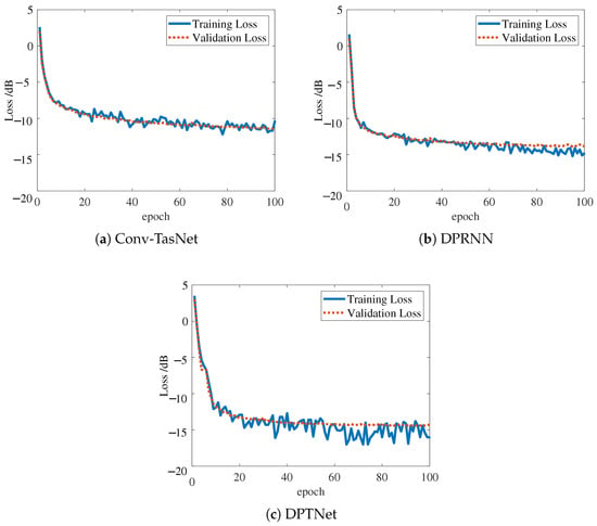
Figure 14.
Training and validation loss versus the number of epochs for 3 models.
4.5. Experiment Results and Discussions
In this section, the effectiveness of trained substation noise separation algorithms will be evaluated under a variety of scenarios. As a benchmark for performance comparison with the proposed deep-learning-based algorithms, the classical noise separation method known as spectral subtraction will be included [38], which subtracts the noise signal spectrum from the noise-bearing signal spectrum to achieve noise reduction.
4.5.1. Scenario I: Performance on the Test Dataset
Let us first take a look at the performance of spectral subtraction, Conv-TasNet, DPRNN, and DPTNet on the test dataset, as shown in Table 5. Recall that the test set comprises a total of 600 audio samples, each of which is a mixture of substation equipment noise and random environment noise (could be bird chirping, insect chirping or human voice) at a random signal-to-noise ratio, with a fixed duration of 3 s and a sampling rate of 48,000 Hz.

Table 5.
Comparison of the separation accuracy of different methods on the test dataset.
It is clear from Table 5 that all three deep learning methods outperform the spectral subtraction method significantly. This notable performance difference can be attributed to the limitations of the spectral subtraction method, which predominantly relies on STFT amplitude spectra for feature extraction, often neglecting the crucial phase spectral information. Deep learning algorithms, on the other hand, exhibit superior feature learning capabilities, enhanced generalization skills to address complex nonlinear relationships, and continuous innovation in model structures and optimization techniques, thus showcasing remarkable performance in the noise separation problem. Among them, DPTNet stands out by achieving the highest SI-SDRi and SDRi metrics while maintaining a minimal model size, making it a favorable choice for noise separation applications in substations.
4.5.2. Scenario II: Single-Source Environment Noise Separation
To further examine the performance of the separation algorithms in various types of environment noise, Table 6 provides a detailed analysis of their effectiveness using three datasets consisting of 200 audio samples, where equipment noise is combined with bird chirping, insect chirping, and human voice at varying signal-to-noise ratios ranging from −5 to 5, respectively. Similar to Table 5, the innovative deep-learning-based methods outperform traditional spectral subtraction techniques across all types of environment noise scenarios.

Table 6.
Comparison of the separation accuracy of different environment noise.
Furthermore, according to Table 6, it becomes evident that distinguishing and isolating human voice amidst the background noise presents a greater challenge compared to bird or insect chirping. This is reflected in the decreased signal-to-disturbance ratio improvement (SI-SDRi) and signal-to-disturbance ratio (SDRi), which exhibit variability across different separation methods (with a dramatic decrease to for spectral subtraction). This difficulty is likely attributed to the spectral overlap between the station noise, concentrated around 100 Hz and its harmonics, and the frequency spectrum of human voice primarily occurring in the low-frequency range of 100 Hz to 1 kHz.
The above experimental results show that the DPTNet model excels in effectively separating the mixture of equipment noise and environment noise. Consequently, the forthcoming subsections will primarily concentrate on further exploring the effectiveness of the DPTNet model.
4.5.3. Scenario III: Multi-Source Environment Noise Separation
Note that the deep learning models are trained using a dataset where the mixed audio is interfered with one single type of environment noise. However, real-world scenarios often involve the presence of multiple noises simultaneously, such as bird chirping and insect chirping. To further assess the separation performance in such complex scenarios, a dataset is constructed where each audio sample is mixed with one type of equipment noise and multiple types of environmental noise. The performance of the DPTNet model under various types of multi-source environment noise is presented in Table 7. A comparison with the single-source case in Table 6 reveals that while the performance may experience a slight degradation in the presence of multiple types of environment noise, it remains sufficiently effective. It indicates that the DPTNet-based noise separation algorithm demonstrates strong adaptability to intricate environments that differ from the training data.

Table 7.
Performance of DPTNet model for multi-source environment noise separation.
4.5.4. Post-Separation Sound Pressure Level Accuracy
It is important to note that the noise monitoring system is designed for the precise evaluation of substation noise levels that exceed the national standard (specifically set at 60 dB in China). As a result, it is crucial to ensure that following the processing of suspected excessive noise (comprising equipment noise and interfering environment noise) by the noise separation algorithm to remove environmental interference, the sound pressure level of the remaining equipment noise closely aligns with its true value. This is essential in order to deliver a dependable final assessment for substation operation and maintenance.
Figure 15 illustrates the distribution of the sound pressure level difference before and after separation using the DPTNet model for the 300 equipment noise and environment noise in the test set. It can be seen that in the case of equipment noise, 91% of the samples exhibit a sound pressure level difference between pre-separation and post-separation falling within the 0–1 dB range, indicating minimal impact on the sound pressure level following the elimination of interfering environment noise. On the other hand, for environment noise, only 64% falls within the 0–1 dB range due to the intrinsic complexity and diverse characteristics of environment noise. As the sound pressure level of the equipment noise is to be assessed in the noise monitoring system, the results demonstrate that the DPTNet-based noise separation model not only effectively removes environment noise but also preserves the accuracy of the equipment noise’s sound pressure level.
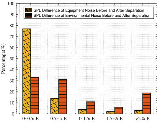
Figure 15.
Sound pressure level difference of noise between before and after separation.
5. End-to-End Substation Noise Monitoring
In order to further demonstrate the practical application of the noise separation algorithm proposed in Section 4 in the noise monitoring system designed in Section 2, this subsection carries out an experimental demonstration and result analysis for two typical application scenarios, as shown in Figure 16 and Figure 17.
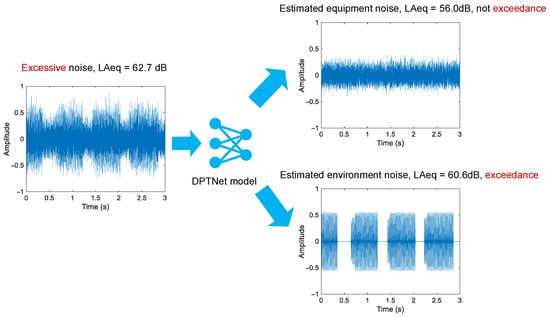
Figure 16.
Separation result of excessive noise, finally environment noise exceedance.
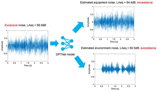
Figure 17.
Separation result of excessive noise, finally equipment noise and environment noise both exceedance.
As shown in Figure 16, the collected noise exhibits an A-frequency weighted sound pressure level of 62.7 dB, which exceeds the threshold of 60 dB and is transmitted to the cloud for noise separation. Subsequent analysis reveals that the sound pressure level of the equipment noise is 56.0 dB, falling below the 60 dB threshold. The discrepancy is primarily attributed to the environment noise registering at 60.6 dB, leading the system to classify this occurrence as a false alarm. Conversely, Figure 17 portrays a scenario where the original collected noise records an A-frequency weighted sound pressure level of 66.9 dB. Following noise separation, the equipment noise’s sound pressure level is determined to be 64.4 dB, surpassing the monitoring threshold. As a result, this event is flagged and documented as an alert instance within the system, triggering the transmission of an exceedance alarm to the relevant substation for prompt intervention.
6. Conclusions and Future Work
This paper presents the design, implementation, and assessment of a substation noise monitoring system developed for the National Grid of China. By employing a terminal-network-cloud layered system architecture, a noise acquisition device is first developed to be installed at the boundaries of substations for capturing real-time noise data. The custom-designed device incorporates frequency weighting through bilinear transformation, time weighting via low-pass filtering, and octave analysis using band-pass filtering. Hardware performance evaluation demonstrates that the device well complies with the requirements outlined in the international standards IEC61672 for Class 1 sound level meters. The devices implemented at substations can then calculate the sound pressure level of real-time noise, log the noise data exceeding the national required threshold and transmit the original audio data to the cloud center for further analysis.
To effectively eliminate background environment noise interference and precisely monitor equipment noise within substations, advanced deep-learning-based noise separation algorithms utilizing Conv-TasNet, DPRNN, and DPTNet models are proposed and implemented at the cloud center of the noise monitoring system. These algorithms are trained using a custom-built dataset of substation noise, and their performance is evaluated and compared to the traditional spectral subtraction method. The results clearly demonstrate the superior efficacy of intelligent noise separation algorithms across a range of experimental scenarios, including single-source and multi-source environmental noise, among which the DPTNet-based model stands out as the most effective. Specifically, Conv-TasNet, DPRNN, DPTNet, and the traditional spectral subtraction achieves an SDRi of 12.6, 13.6, 14.2, and 4.6, respectively, and an SI-SNRi of 11.8, 12.4, 12.9, and 4.1, respectively, on the test set. Furthermore, post-separation noise analysis reveals that 91% of equipment noise displays a sound pressure level difference within 1 dB, showcasing the system’s ability to facilitate precise noise monitoring for substation operations and maintenance.
Author Contributions
Methodology, W.C. and Y.L.; software, W.C. and Y.L.; resources, W.C. and Y.L.; data curation, W.C. and Y.L.; writing—original draft preparation, W.C., Y.L. and Y.G.; writing—review and editing, Y.G.; supervision, Y.G., J.H., Z.L. and J.Z.; project administration, Y.G., J.H., Z.L. and J.Z.; funding acquisition, Y.G., J.H., Z.L. and J.Z. All authors have read and agreed to the published version of the manuscript.
Funding
This research was funded by Open Fund of State Key Laboratory of Power Grid Environmental Protection (No. GYW51202201381).
Data Availability Statement
Restrictions apply to the availability of these data. Data were obtained from State Key Laboratory of Power Grid Environmental Protection, Wuhan, China, and are available from the authors with the permission of State Key Laboratory of Power Grid Environmental Protection, Wuhan, China.
Conflicts of Interest
The authors declare no conflicts of interest.
References
- Fan, X.; Li, L.; Zhao, L.; He, H.; Zhang, D.; Ren, Z.; Zhang, Y. Environmental noise pollution control of substation by passive vibration and acoustic reduction strategies. Appl. Acoust. 2020, 165, 107305. [Google Scholar] [CrossRef]
- Law of the People’s Republic of China on Prevention and Control of Pollution from Environmental Noise, 2021. Available online: https://digital.library.unt.edu/ark:/67531/metadc12065/ (accessed on 20 April 2024).
- Jun, L.; Li, L.; Yongxiang, Z.; Zhigang, C.; Xiaopeng, F. Annoyance evaluation of noise emitted by urban substation. J. Low Freq. Noise, Vib. Act. Control. 2021, 40, 2106–2114. [Google Scholar] [CrossRef]
- Santini, S.; Ostermaier, B.; Vitaletti, A. First experiences using wireless sensor networks for noise pollution monitoring. In Proceedings of the Workshop on Real-World Wireless Sensor Networks (REALWSN), New York, NY, USA, 1–4 April 2008; pp. 61–65. [Google Scholar]
- Hakala, I.; Kivelä, I.; Ihalainen, J.; Luomala, J.; Gao, C. Design of low-cost noise measurement sensor network: Sensor function design. In Proceedings of the 2010 First International Conference on Sensor Device Technologies and Applications (SENSORDEVICES), Venice, Italy, 18–25 July 2010; IEEE: Piscataway, NJ, USA, 2010; pp. 172–179. [Google Scholar]
- Noriega-Linares, J.E.; Navarro Ruiz, J.M. On the application of the raspberry Pi as an advanced acoustic sensor network for noise monitoring. Electronics 2016, 5, 74. [Google Scholar] [CrossRef]
- Aurino, F.; Folla, M.; Gargiulo, F.; Moscato, V.; Picariello, A.; Sansone, C. One-class SVM based approach for detecting anomalous audio events. In Proceedings of the 2014 International Conference on Intelligent Networking and Collaborative Systems (INCOS), Salerno, Italy, 10–12 September 2014; IEEE: Piscataway, NJ, USA, 2014; pp. 145–151. [Google Scholar]
- Fan, S.; Li, J.; Li, L.; Chu, Z. Noise annoyance prediction of urban substation based on transfer learning and convolutional neural network. Energies 2022, 15, 749. [Google Scholar] [CrossRef]
- Yu, Z.; Wei, Y.; Niu, B.; Zhang, X. Automatic Condition Monitoring and Fault Diagnosis System for Power Transformers Based on Voiceprint Recognition. IEEE Trans. Instrum. Meas. 2024, 73, 1–11. [Google Scholar] [CrossRef]
- Ntalampiras, S.; Potamitis, I.; Fakotakis, N. Probabilistic novelty detection for acoustic surveillance under real-world conditions. IEEE Trans. Multimed. 2011, 13, 713–719. [Google Scholar] [CrossRef]
- Ntalampiras, S. Universal background modeling for acoustic surveillance of urban traffic. Digit. Signal Process. 2014, 31, 69–78. [Google Scholar] [CrossRef]
- Wu, X.; Zhou, N.; Pei, C.; Hu, S.; Huang, T.; Ying, L. Separation methodology of audible noise of UHV AC substations. High Volt. Eng. 2016, 42, 2625–2632. [Google Scholar]
- Shams, M.A.; Anis, H.I.; El-Shahat, M. Denoising of heavily contaminated partial discharge signals in high-voltage cables using maximal overlap discrete wavelet transform. Energies 2021, 14, 6540. [Google Scholar] [CrossRef]
- Hao, W.; Jun, C.; Shuai, A.; Shu, X. Application of SCA-VMD in Noise Reduction of Transformer Sound Signal. Power Gener. Technol. 2020, 41, 186–189. [Google Scholar]
- Qian, Y.m.; Weng, C.; Chang, X.k.; Wang, S.; Yu, D. Past review, current progress, and challenges ahead on the cocktail party problem. Front. Inf. Technol. Electron. Eng. 2018, 19, 40–63. [Google Scholar] [CrossRef]
- Toroghi, R.M.; Faubel, F.; Klakow, D. Multi-channel speech separation with soft time-frequency masking. In Proceedings of the SAPA-SCALE Conference, Portland, OR, USA, 7–8 September 2012. [Google Scholar]
- Fan, S.; Liu, J.; Li, L.; Li, S. Noise Separation Technique for Enhancing Substation Noise Assessment Using the Phase Conjugation Method. Appl. Sci. 2024, 14, 1761. [Google Scholar] [CrossRef]
- Wang, G.; Wang, Y.; Min, Y.; Lei, W. Blind source separation of transformer acoustic signal based on sparse component analysis. Energies 2022, 15, 6017. [Google Scholar] [CrossRef]
- Dong, S.; Wang, P.; Abbas, K. A survey on deep learning and its applications. Comput. Sci. Rev. 2021, 40, 100379. [Google Scholar] [CrossRef]
- Mathew, A.; Amudha, P.; Sivakumari, S. Deep learning techniques: An overview. In Advanced Machine Learning Technologies and Applications: Proceedings of AMLTA 2020; Springer: Berlin/Heidelberg, Germany, 2021; pp. 599–608. [Google Scholar]
- Abulizi, J.; Chen, Z.; Liu, P.; Sun, H.; Ji, C.; Li, Z. Research on voiceprint recognition of power transformer anomalies using gated recurrent unit. In Proceedings of the 2021 Power System and Green Energy Conference (PSGEC), Virtual, 21–22 August 2021; IEEE: Piscataway, NJ, USA, 2021; pp. 743–747. [Google Scholar]
- Ma, X.; Luo, Y.; Shi, J.; Xiong, H. Acoustic Emission Based Fault Detection of Substation Power Transformer. Appl. Sci. 2022, 12, 2759. [Google Scholar] [CrossRef]
- Han, S.; Wang, B.; Liao, S.; Gao, F.; Chen, M. Defect Identification Method for Transformer End Pad Falling Based on Acoustic Stability Feature Analysis. Sensors 2023, 23, 3258. [Google Scholar] [CrossRef] [PubMed]
- Hershey, J.R.; Chen, Z.; Le Roux, J.; Watanabe, S. Deep clustering: Discriminative embeddings for segmentation and separation. In Proceedings of the 2016 IEEE International Conference on Acoustics, Speech and Signal Processing (ICASSP), Shanghai, China, 20–25 March 2016; pp. 31–35. [Google Scholar]
- Stoller, D.; Ewert, S.; Dixon, S. Wave-u-net: A multi-scale neural network for end-to-end audio source separation. In Proceedings of the 19th International Society for Music Information Retrieval Conference (ISMIR 2018), Paris, France, 23–27 September 2018; pp. 334–340. [Google Scholar]
- Luo, Y.; Mesgarani, N. Conv-tasnet: Surpassing ideal time–frequency magnitude masking for speech separation. IEEE/Acm Trans. Audio Speech Lang. Process. 2019, 27, 1256–1266. [Google Scholar] [CrossRef] [PubMed]
- Subakan, C.; Ravanelli, M.; Cornell, S.; Bronzi, M.; Zhong, J. Attention is all you need in speech separation. In Proceedings of the 2021 IEEE International Conference on Acoustics, Speech and Signal Processing (ICASSP), Oronto, ON, Canada, 6–11 June 2021; IEEE: Piscataway, NJ, USA, 2021; pp. 21–25. [Google Scholar]
- Zhao, S.; Ma, B. Mossformer: Pushing the performance limit of monaural speech separation using gated single-head transformer with convolution-augmented joint self-attentions. In Proceedings of the 2023 IEEE International Conference on Acoustics, Speech and Signal Processing (ICASSP), Rhodes Island, Greece, 4–10 June 2023; IEEE: Piscataway, NJ, USA, 2023; pp. 1–5. [Google Scholar]
- IEC 61672-3; Electroacoustics-Sound Level Meters-Part 3: Periodic Tests, Standard. International Electrotechnical Commission: London, UK, 2013.
- GB/T 3241-2010; Electroacoustics Octave and Fractional Octave Filters Part 1: Specifications; National Standard of the People’s Republic of China. China Standard Publishing House: Beijing, China, 2010.
- Mahdi, J.F. Frequency analyses of human voice using fast Fourier transform. Iraqi J. Phys. 2015, 13, 174–181. [Google Scholar] [CrossRef]
- Rivera, M.; Edwards, J.A.; Hauber, M.E.; Woolley, S.M. Machine learning and statistical classification of birdsong link vocal acoustic features with phylogeny. Sci. Rep. 2023, 13, 7076. [Google Scholar] [CrossRef]
- Branding, J.; von Hörsten, D.; Böckmann, E.; Wegener, J.K.; Hartung, E. InsectSound1000 An insect sound dataset for deep learning based acoustic insect recognition. Sci. Data 2024, 11, 475. [Google Scholar] [CrossRef]
- Luo, Y.; Chen, Z.; Yoshioka, T. Dual-Path RNN: Efficient Long Sequence Modeling for Time-Domain Single-Channel Speech Separation. In Proceedings of the 2020 IEEE International Conference on Acoustics, Speech and Signal Processing (ICASSP), Barcelona, Spain, 4–8 May 2020; pp. 46–50. [Google Scholar]
- Chen, J.; Mao, Q.; Liu, D. Dual-Path Transformer Network: Direct Context-Aware Modeling for End-to-End Monaural Speech Separation. In Proceedings of the Interspeech 2020, Shanghai, China, 25–29 October 2020; pp. 2642–2646. [Google Scholar]
- Vincent, E.; Gribonval, R.; Févotte, C. Performance measurement in blind audio source separation. IEEE Trans. Audio Speech Lang. Process. 2006, 14, 1462–1469. [Google Scholar] [CrossRef]
- Le Roux, J.; Wisdom, S.; Erdogan, H.; Hershey, J.R. SDR–half-baked or well done? In Proceedings of the 2019 IEEE International Conference on Acoustics, Speech and Signal Processing (ICASSP), Brighton, UK, 12–17 May 2019; pp. 626–630. [Google Scholar]
- Upadhyay, N.; Karmakar, A. Speech enhancement using spectral subtraction-type algorithms: A comparison and simulation study. Procedia Comput. Sci. 2015, 54, 574–584. [Google Scholar] [CrossRef]
Disclaimer/Publisher’s Note: The statements, opinions and data contained in all publications are solely those of the individual author(s) and contributor(s) and not of MDPI and/or the editor(s). MDPI and/or the editor(s) disclaim responsibility for any injury to people or property resulting from any ideas, methods, instructions or products referred to in the content. |
© 2024 by the authors. Licensee MDPI, Basel, Switzerland. This article is an open access article distributed under the terms and conditions of the Creative Commons Attribution (CC BY) license (https://creativecommons.org/licenses/by/4.0/).