Abstract
This paper presents the design and performance of an energy subsystem (ES) dedicated to hybrid energy harvesters (HEHs): wave energy converters (WECs) combined with photovoltaic panels (PVPs). The considered ES is intended for compact HEHs powering autonomous end-node devices in distributed IoT networks. The designed ES was tested experimentally and evaluated in relation to the mobile and wireless distributed communication use case. The numerical evaluation was based on the balance of the harvested energy versus the energy consumed in the considered use case. The evaluation results proved that the ES ensured energy surplus over the considered IoT node consumption. It confirmed the proposed solution as convenient to the compact HEHs applied for sustainable IoT devices to power them with renewable energy harvested from light and sea waves. It was found that the proposed ES can provide the energy autonomy of the IoT end node and increase its reliability through a hybrid energy-harvesting approach.
1. Introduction
The primary aim of the works outlined in this paper was to contribute to the sustainable development of mobile and wireless autonomous devices by providing them with a reliable and hybrid method of power supply: water wave energy and light energy. For the purposes of evaluating the proposed hybrid solution, a use case scenario of one of the IoT devices developed by the first author of this article was adapted. The considered use case scenario is further described in Section 3.
The design and proper application of a hybrid wave–photovoltaic energy generation system requires the analysis of solar irradiance at different depths for pure water and for real water transparency. Such analysis oriented towards future maritime application was carried out by the second author of this article and is detailed in Section 2.
The first wave energy converter (WEC) was patented in 1799 [1]. This early WEC harvested the energy of waves and converted it into useful mechanical work. Afterwards, new WEC applications emerged as model-scale laboratory experiments and full-scale constructions [2,3], representing various concepts [4] and different control strategies [5]. Modern designs involve new materials converting the vibrations derived from water waves into electric charge using maintenance-free piezoelectric materials (PMs) [6,7]. The advantages resulting from maintenance-free operation are crucial for WECs applied to power compact, autonomous, and sustainable IoT devices. This type of application importance is emerging for the development of industries [8], safety [9,10], and human health [11,12].
The photoelectric effect was discovered in 1839 [13]. It enabled the later conversion of light energy into an electrical form with the use of an operating solar cell in 1883 [14]. The developed solar cells were finally considered efficient in 1954 [15]. Photovoltaic cell applications in the form of photovoltaic panels (PVPs) became widely available, common, and efficient [16]. They found applications for compact, autonomous, and sustainable IoT devices [17], such as solar-powered BLE beacons [18], sensors [19], and also devices supplying energy in various ways: indoor light energy [20], hybrid radio and light energy [21,22], or hybrid thermal and light energy [23].
A hybrid approach to energy harvesting, combining water-resistant PVPs with WEC, is a promising solution for autonomous power supply systems. The most promising advantages of such systems include the following:
- Decreased dependence on sunlight and improved energy generation as the wave energy component ensures a steady power output, decreasing the unstable PV source component. WECs can harvest the energy when solar conditions are insufficient, and PVPs can harvest it when the water is calm;
- Potential to generate more electricity in maritime and coastal areas with access to both sunlight and ocean waves;
- Wave energy converters play a vital role in the hybrid system, capturing the kinetic energy of ocean waves and converting it into electricity.
The concept of hybrid energy harvesting for IoT applications was previously proposed in [24,25]. The hybrid harvesting of energy from light and environmental vibrations is considered there. The results presented in [24] confirm the circuits considered to be operating. However, no measurements under the load with output energy or output power values have been reported. Thus, it was impossible to evaluate such results from the point of view of practical use-case energy consumption. The output power of the solution reported in [25] ranged from 0.5 mW to 2.7 mW. Such power was not enough for the considered use case [26], which consumes more than 3 mW for IoT communication and the actuation process. Consequently, the issue of practical and effective energy harvesting, storing, and management within energy-autonomous IoT end-node compact applications remains open and needs to be resolved.
The freely available energy harvested in such a way has a low density and needs to be properly processed to be used for the intended purpose of powering the IoT node. To achieve this, an energy harvester (EH) equipped with an energy subsystem (ES) oriented towards optimal processing, storing, and management of this dissipated and harvested energy needs to be developed. This demand has motivated the authors to perform the works presented and evaluated in this paper. The intended ES was developed by the authors to be automated, autonomous, and compact for modern IoT devices. The hybrid approach of wave and light energy harvesting provides complementary energy generation resulting in higher stability and reducing the capacity of energy storage for the uninterrupted IoT devices’ power supply. The proposed solution is resistant to the absence of one of the power sources, irradiation or wave. The novelty of the proposed solution is the optimized ES of the hybrid light–wave energy harvester (HEH) oriented towards cutting-edge applications in IoT devices.
2. Solar Irradiance and Photovoltaic Technologies Analysis for Maritime Application
The design of a hybrid wave–photovoltaic energy generation system requires analysis of solar irradiance at different depths for pure water and for real water transparency. According to [27], solar irradiance calculated from the absorption coefficient [28] at 22 °C and different depths of pure water showed light penetration over 100 m for narrower bands around blue color wavelengths, as shown in Figure [29]. The light with wavelengths longer or shorter than blue is absorbed by water to a greater extent. The design of a hybrid wave–photovoltaic energy generation system requires the analysis of available technologies for underwater application purposes. The phenomenon of the irradiation filtering effect is reported in [30]. Solar cells made of amorphous silicon (a-Si) spectral sensitivity are able to absorb visible light wavelengths that penetrate water and provide less reduction in efficiency compared to crystalline silicon cells assuming underwater operation. Power output can be sufficient for small underwater electronic devices and sensors. Other considered technologies of photovoltaic modules include high-bandgap solar cells (gallium arsenide and cadmium telluride), which have wider bandgaps allowing for better absorption of the blue-shifted underwater light spectrum and can operate at higher efficiency and significant depth compared to silicon cells. The third generation of organic dye-sensitized solar cells (DSSCs) can be engineered with pigments optimized for the underwater light spectrum and have the potential for low-cost fabrication from abundant materials with results comparable to the underwater performance of a-Si cells. Monocrystalline and polycrystalline silicon cells are existing commercial technologies optimized to obtain maximum efficiency in the air but can also generate power when submerged, although efficiency drops significantly. The key advantages of non-perovskite options are their greater inherent stability in water compared to moisture-sensitive perovskites and the ability to tune their optoelectronic properties for the underwater light environment through material engineering [27,28]. Underwater application of PV panels faces challenges and limitations due to reduced power yield, potential water absorption of solar radiation thereby reducing panel efficiency, and the presence of toxic substances like cadmium telluride or lead in solar photovoltaics that can contaminate water bodies when in contact with water; however, more efficient water cooling and self-cleaning of the panels by water are factors improving the energy conversion efficiency. The advantages of underwater or floating PV system applications are related to the efficient use of space. Floating solar PV panels allow for the efficient use of terrain by installing solar panels. The most promising technology for underwater applications are perovskites. The most significant disadvantage is their instability and the fast degradation of irradiation levels on the Earth’s surface; therefore, they are only acceptable for IoT purposes or underwater, where part of the irradiation is reflected and absorbed, so they are not harmful for perovskite photovoltaic modules. Perovskite solar cells (PSCs) provide several advantages for underwater photovoltaic (PV) applications. Perovskites have very high absorption coefficients, allowing thin films to absorb a large portion of the solar spectrum. This is beneficial for underwater operations where light is absorbed and reflected by water. Moreover, the bandgap of perovskites can be tuned by varying their composition for operation optimization in the underwater light spectrum. Perovskite solar cells are very thin (approximately 1 micron), lightweight, and can conform to curved surfaces, making them ideal for integration into underwater vehicles and constructions. Developed water and heat-resistant perovskite cells are constructed by encapsulating the perovskite layer with protective coatings like titanium dioxide. These cells survive direct water exposure and 100 °C heat. Manufactured perovskite cells show 10.49 mW·cm−2 power density underwater at 20 cm depth. Moreover, perovskite solar technology shows great promise for enabling self-powered underwater vehicles. Inorganic perovskite compositions have shown promising stability and performance when immersed in water compared to other PV technologies. Perovskite solar cells have achieved over 25% efficiency, offering high power output even with reduced light transmission under water. Manufacturing of perovskites is low-cost compared to other technologies. They can be processed from low-cost precursor materials and printed, making them economically attractive for underwater PV systems. State-of-the-art PV technologies have shown perovskite as an attractive emerging technology to harvest solar energy in underwater environments [27,28,30]. The key limitations of perovskite photovoltaics application for underwater applications are related to moisture instability. They are highly sensitive to moisture, which can cause rapid degradation. Water ingress is a major challenge for underwater operations. Effective encapsulation strategies are required to protect the perovskite layer from the aqueous environment, but it is also a concern for other technologies, although the degradation time due to water contact is longer. The light absorption and charge transport properties of perovskites can be affected by hydrostatic pressure when submerged under water. Therefore, novel device architectures are required to mitigate these effects. Scalable manufacturing techniques like roll-to-roll coating are also required to produce large-area underwater perovskite PV modules cost-effectively. Marine organisms like algae and barnacles can accumulate on submerged surfaces, reducing light transmission to the perovskite cell and decreasing their effectiveness. Therefore, periodic cleaning may be required. For practical underwater applications, perovskite PV systems must provide long operating lifetimes of at least 15 years. This remains a key challenge, given the instability of many perovskite compositions. Many high-performance perovskites contain lead, which raises environmental and health concerns if the devices are damaged and lead leaches into the water. However, lead-free and moisture-stable perovskite materials are under development with effective encapsulation methods and scalable fabrication processes to overcome these limitations for underwater perovskite PV applications. Concluding the solar irradiance and photovoltaic technologies analysis, the design of the target photovoltaic system should be carried out in accordance with the target environmental conditions, taking into account the above-described features of photovoltaic panels. Saltwater corrosion can significantly reduce the lifespan of submerged perovskite photovoltaic modules. Corrosion risks are considered for perovskite PV cells and electrical components: saltwater can accelerate the decomposition of the perovskite layer, leading to a loss in efficiency. Moreover, it can corrode metallic parts within the solar cell, such as electrodes and interconnectors. Submerged PV panels should pass the “IEC 61701 Salt Mist Corrosion Test”. To avoid corrosion effects, it is recommended to apply encapsulation using water-resistant glass or polymers to block saltwater and oxide penetration.
3. Mobile and Wireless Distributed Communication Use Case
To evaluate the designed HEH, a real-life use case scenario was considered. The adapted use case scenario involved a low-power IoT device commercially offered by the MPICOSYS company [31]. The involved device consists of a 2.71” monochrome electronic paper display (e-paper) [32] and an ARM Cortex-M4 microcontroller enabling (long-range) modulation [33]. This IoT device and its features, including energy consumption, are detailed in [26,34]. According to the experiments carried out there, its energy demand per operating cycle is equal to 26.3 mJ, wherein, apart from the idle part of the cycle, the communication and actuation consume the amount of energy 21.5 mJ in 7.1 s, i.e., 3.03 mW of mean power [26]. Such mean power consumption is related to the uplink–downlink LoRa communication and actuation by the e-paper display content refresh. An example of the screen content after the operating cycle is shown in Figure 1.
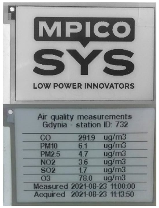
Figure 1.
The 2.71” e-paper display of the IoT device before (on the top) and after the operating cycle of uplink–downlink LoRa communication and the display update (on the bottom) [26].
Within the current use-case scenario, this IoT device is considered to be powered by the distributed and harvested energy of waves and light. Consequently, the effective power supply of such a device using HEH requires a dedicated ES design.
4. Energy Subsystem of the Hybrid Energy Harvester
The essential element of the HEH is the ES securing appropriate conversion, storage, and management of the distributed and harvested energy of the waves and light. The ES design is presented in Figure 2. It converts the energy of high-voltage peaks of the PM-based WEC applied to the and terminals. This converted energy is stored in tantalum capacitors –. The process of wave energy conversion was reported in [26,34]. The light energy harvested with the use of PVP is applied to the terminal and is also collected and stored in a battery-less manner in –. Energy management is realized with the use of supervisory circuit with output, low-voltage input boost regulator , low dropout (LDO) regulator , P-channel enhancement mode MOSFET transistor , and their circuits passive components: diodes D, capacitors C, and resistors R. The electronic components applied to the ES are detailed including the manufacturers’ parts numbers in [34].
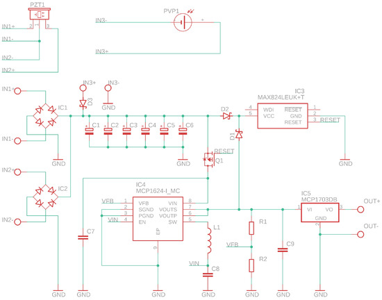
Figure 2.
The electronic circuit of the energy subsystem designed and applied to the hybrid energy harvester of wave and light energy.
The electronic circuit designed and implemented by the first author operates as follows. The – are charged with energy from the WEC or PVP. is a bimorph piezoelectric ceramic PZT transducer with a brass membrane. is a polycrystalline silicon photovoltaic panel. – voltage is monitored using the pin of the . The monitored voltage corresponds to the harvested and stored energy. When the required amount of energy is collected in –, the monitored voltage reaches the threshold value, and the output of turns on the . Consequently, is supplied with the energy stored in – and boosts the voltage applied to the pin. remains turned on, and the stored energy is pumped out effectively, even when – voltage drops below ’s threshold. – ensure the appropriate direction of energy flow. adjusts the terminal voltage to the level required by the load: the IoT device of the considered use case. The load is supplied as long as the energy storage voltage does not drop below the operating input voltage of . Each subsequent switching-on will happen when – collects the amount of energy required for at least one operating cycle.
5. Experimental Research
Model physical experiments on HEH for harvesting wave energy and light energy were carried out indoors and apart. A bimorph piezoelectric ceramic PZT transducer with a brass membrane was connected to the and terminals. The transducer had brass membrane dimensions of 33 mm per 80 mm and PZT dimensions of 30 mm per 60 mm, with an overall thickness of 0.6 mm. The influence of wave force was modeled by applying a force causing deformation of the transducer in the indoor experiment. The transducer generated a voltage under the influence of a force with a frequency of 1 Hz. The force applied to the center of the transducer plane deformed it longitudinally, wherein the transducer’s long ends were fixed to a fixed support. This resulted in a deformation of the membrane with an amplitude of 3 mm, corresponding to 6 mm peak-to-peak deformation. The model experiment on wave energy harvesting was performed in line with the method detailed in [34]. A PVP made of polycrystalline silicon was connected to the terminal. The PVP’s open circuit voltage was 5.5 V, and its short circuit current was 110 mA. The panel had dimensions of 65 mm per 65 mm and a thickness of 3 mm. It generated a voltage under the light radiation model with an illuminance of 5600 lx. Such illuminance corresponds to a surface power density of 0.82 mW·cm−2 in the middle of the visible light spectrum at 555 nm. The experimental setup for the light energy harvesting is shown in Figure 3.
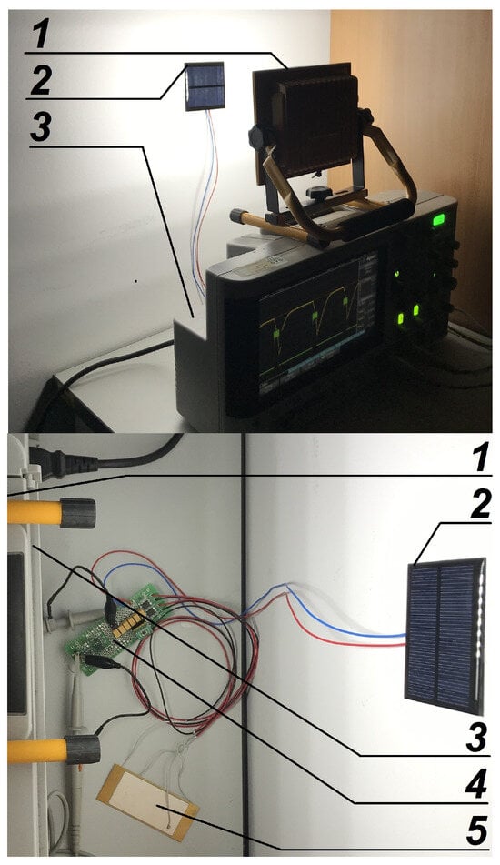
Figure 3.
The experimental setup operating under the model light radiation (1) with a photovoltaic panel (2) and digital oscilloscope (3), connected to the energy subsystem (4), tested separate from the PZT transducer (5) in a measurement room (side view on the top and top view on the bottom).
The energy harvester load was modeled with a resistance of 2 kΩ supplied from the ES OUT terminal. This approach was applied in both experiments: harvesting energy with the use of PZT and harvesting energy with the use of PVP. In the experiments, the voltage of the energy stored in – and the voltage supplied to the load were measured using an AGILENT TECHNOLOGIES DSO-X 2004A digital oscilloscope. The energy stored in the capacitors can be calculated as (1), wherein is the total capacitance of the energy storage equal to 6 mF [34].
The energy consumed by the load supplied over a period of T can be calculated as (2), wherein is applied resistance of 2 kΩ [34].
Such derived amounts of energy made it possible to evaluate the performance of the designed hybrid, wave and light energy harvester.
6. Results
According to the physical model experiment for harvesting wave energy, the voltage increased from 0 V to 4.74 V over 348 s. When the given amount of energy was collected in the storage, and the voltage reached the threshold value, the load was supplied with the harvested energy for 7 s at a mean voltage of 3.2 V. The ES maintained the required voltage of 3.2 V. The measured and voltage waveforms are presented in Figure 4.
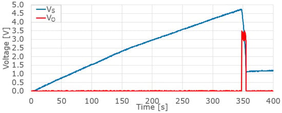
Figure 4.
The voltages measured during the operation of the wave energy harvester: on the energy storage (blue) and on the load (red).
In the experiment on harvesting wave energy, the ES collected 67.5 mJ of energy in 348 s and then supplied the load with the energy of 37.2 mJ in 7 s. The calculated waveforms of and energy are presented in Figure 5.
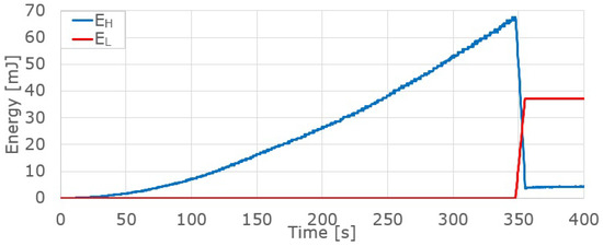
Figure 5.
The energy calculated for the operation of the wave energy harvester: collected in the energy storage (blue) and supplied to the load (red).
According to the physical model experiment for harvesting light energy, the voltage increased from 0 V to 4.78 V over 52.5 s. When the given amount of energy was collected in the storage, and the voltage reached the threshold value, the load was supplied with the harvested energy for 9.7 s at a mean voltage of 3.2 V. The ES maintained the required voltage of 3.2 V. The measured and voltage waveforms are presented in Figure 6.
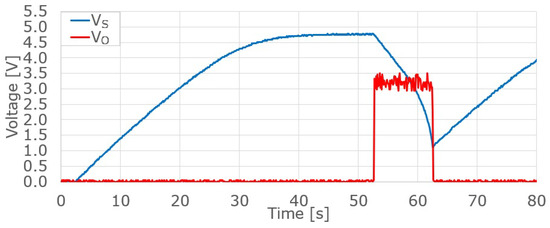
Figure 6.
The voltages measured during the operation of the light energy harvester: on the energy storage (blue) and on the load (red).
During the experiment for harvesting light energy, the ES collected 67.5 mJ of energy in 52.6 s and then supplied the load with 50.6 mJ of energy in 9.7 s. The calculated waveforms of and energy are presented in Figure 7.
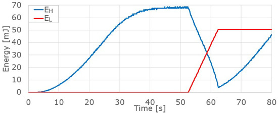
Figure 7.
The energy calculated for the operation of the light energy harvester: collected in the energy storage (blue) and supplied to the load (red).
A summary of the HEH performance versus the energy requirements of the considered use-case scenario is presented in Table 1.

Table 1.
Summary of energy conversion performance with the use of HEH ES with WEC and PVP for the load model.
According to the results of the experiment, the energy supplied to the load from ES with energy harvesting using WEC and PVP was equal to 37.2 mJ and 50.6 mJ, respectively. According to the considered use case, the demanded energy amount was 26.3 mJ. All these values correspond to an operating cycle shorter than 6 min. A 41.5% and 92.4% surplus of energy delivered over the energy demanded was demonstrated for the WEC and PVP, respectively. These results of the model experiment confirmed that the HEH with designed and applied ES enables efficient energy harvesting, storage, and management in the considered hybrid applications of the IoT-intended energy harvesters.
The ES supplied the load with energy of 37.2 mJ in 7 s during model experiments related to wave energy harvesting. This amount of energy and time corresponds to an average power of 5.3 mW delivered to the load. During light harvesting model experiments, the ES delivered 50.6 mJ of energy to the load in 9.7 s. This amount of energy and time corresponds to an average power of 5.2 mW delivered to the load. Both of these results exceed almost twice the 2.7 mW of the output power reported in related works [25].
Despite the proposed solution being a hybrid type, the results of the current indoor experiment were individually compared with a non-hybrid WEC and non-hybrid light energy harvester for better evaluation. The results of works related to the EPAM-based WEC, which also uses modern materials [35], were compared. The electrical energy harvested there from the water wave force with a frequency of 1 Hz at various wave heights was 7.3 mJ at HW of 2.0 cm, 15.8 mJ at HW of 3.0 cm, 23.5 mJ at HW of 4.0 cm, and 26.4 mJ at HW of 6.0 cm. This performance seems to be energetically more promising than that of PZT-based WEC in the current study. Nevertheless, an EPAM-based solution, due to the principle operation of the material, needs an external high-voltage source to operate [35]. This feature makes EPAM-based WEC not compact and autonomous enough. Hereby, the current solution is more applicable to compact, autonomous, distributed, and sustainable IoT nodes.
7. Conclusions
This article presented the design and performance of the HEH ES dedicated to compact energy harvesters: WECs and PVPs. The considered ES was intended for compact HEHs powering autonomous devices in distributed IoT networks. The designed ES was run and experimentally verified. The model experiment reflected the operation of the designed ES with WEC, PVP, and the load model. According to the results and comparison presented in Section 5, the considered ES made significant contributions to compact HEHs and can be applied to sustainable IoT network devices to power them with renewable energy, such light or sea waves, depending on which is more readily available.
In addition to satisfying 75% ES efficiency for PVP, the 55.1% ES efficiency for WEC needs to be improved in future works. As a result, the improvement in efficiency will allow for smaller capacity for energy storage, reducing the costs of HEH ES.
The present study was biased by the limitations resulting from the indoor experimental method. Moreover, the study was mainly focused on the designed and applied electronic energy subsystem that enables efficient energy harvesting, storage, and management. Therefore, an approach was used to evaluate energy balance between energy harvested using the proposed energy subsystem and the energy consumed by the considered IoT device. Such an approach is relevant because it is based on registered data measured during original physical experiments detailed in this paper. These limitations might result in the omission of the impact of important phenomena and constraints related to the hydromechanical harvesting of wave energy and photovoltaic harvesting of light energy in environmental conditions. Despite these limitations, the operation of the ES in the hybrid energy harvesting system has been confirmed, and this indicates the validity of this development direction towards energetically sustainable, autonomic, and distributed IoT end-nodes. Consequently, in future research, the authors intend to develop hydromechanical and photovoltaic parts to perform experiments in water waves and natural light.
Author Contributions
Conceptualization, M.D., P.K. and J.G.; methodology, M.D., P.K. and J.G.; software, M.D.; validation, M.D., P.K. and J.G.; formal analysis, M.D. and P.K.; investigation, M.D.; resources, M.D.; data curation, M.D.; writing—original draft preparation, M.D., P.K. and J.G.; writing—review and editing, P.K., J.G. and M.D.; visualization, M.D. and P.K.; supervision, J.G.; project administration, M.D., P.K. and J.G.; funding acquisition, M.D. and J.G. All authors have read and agreed to the published version of the manuscript.
Funding
The paper work and APC was funded by the Faculty of Electrical and Control Engineering at the Gdańsk University of Technology. The laboratory equipment was made available by MpicoSys Embedded Pico Systems Sp. z o.o.
Data Availability Statement
Data are contained within the article.
Conflicts of Interest
Author Marcin Drzewiecki is employed by the company MpicoSys Embedded Pico Systems Sp. z o.o. The remaining authors declare that the research was conducted in the absence of any commercial or financial relationships that could be construed as a potential conflict of interest. The authors declare that this study received free access to the laboratory equipment from MpicoSys Embedded Pico Systems Sp. z o.o. The funder was not involved in the study design, collection, analysis, interpretation of data, the writing of this article or the decision to submit it for publication.
Abbreviations
The following abbreviations are used in this manuscript:
| AM | Air mass |
| APC | Article processing charges |
| a-Si | Amorphous silicon |
| DC | Direct current |
| DSSC | Dye-sensitized solar cells |
| EPD | Electronic paper display |
| EH | Energy harvester |
| ES | Energy subsystem |
| HEH | Hybrid energy harvester |
| IoT | Internet of Things |
| IPSC | Inorganic perovskite solar cells |
| LDO | Low dropout |
| MOSFET | Metal-oxide semiconductor field-effect transistor |
| NREL | National Renewable Energy Laboratory |
| PCE | Power conversion efficiency |
| PEC | Prototype power electronic circuit |
| PM | Piezoelectric material |
| PSC | Perovskite solar cells |
| PVP | Photovoltaic panel |
| PZT | Lead zirconate titanate |
| WEC | Wave energy converter |
References
- Girard, P.; Girard, S. BREVET D’INVENTION DE QÙINZE ANS, Pour divers moyens d’employer les vagues de la mer, comme moteurs. Paris 1799, 349, 13. [Google Scholar]
- Clément, A.; McCullen, P.; Falcão, A.; Fiorentino, A.; Gardner, F.; Hammarlund, K.; Lemonis, G.; Lewis, T.; Nielsen, K.; Petroncini, S.; et al. Wave energy in Europe: Current status and perspectives. Renew. Sustain. Energy Rev. 2002, 6, 5. [Google Scholar] [CrossRef]
- Lagoun, M.S.; Benalia, A.; Benbouzid, M.E.H. Ocean wave converters: State of the art and current status. In Proceedings of the 2010 IEEE ENERGYCON, Manama, Bahraïn, 18–22 December 2010; pp. 636–642. [Google Scholar]
- Jusoh, M.A.; Ibrahim, M.Z.; Daud, M.Z.; Albani, A.; Mohd Yusop, Z. Hydraulic Power Take-Off Concepts for Wave Energy Conversion System: A Review. Energies 2019, 12, 4510. [Google Scholar] [CrossRef]
- Maria-Arenas, A.; Garrido, A.J.; Rusu, E.; Garrido, I. Control Strategies Applied to Wave Energy Converters: State of the Art. Energies 2019, 12, 3115. [Google Scholar] [CrossRef]
- Nabavi, S.F.; Farshidianfar, A.; Afsharfard, A.; Khodaparast, H.H. An ocean wave-based piezoelectric energy harvesting system using breaking wave force. Int. J. Mech. Sci. 2019, 151, 498–507. [Google Scholar] [CrossRef]
- Chiba, S.; Waki, M. Innovative power generator using dielectric elastomers (creating the foundations of an environmentally sustainable society). Sustain. Chem. Pharm. 2020, 15, 100205. [Google Scholar] [CrossRef]
- Miraz, M.H.; Ali, M.; Excell, P.S.; Picking, R. A review on Internet of Things (IoT), Internet of Everything (IoE) and Internet of Nano Things (IoNT). In Proceedings of the 2015 Internet Technologies and Applications (ITA), Wrexham, UK, 8–11 September 2015; pp. 219–224. [Google Scholar] [CrossRef]
- Agarwal, K.; Agarwal, A.; Misra, G. Review and Performance Analysis on Wireless Smart Home and Home Automation using IoT. In Proceedings of the 2019 Third International conference on I-SMAC (IoT in Social, Mobile, Analytics and Cloud) (I-SMAC), Palladam, India, 12–14 December 2019; pp. 629–633. [Google Scholar] [CrossRef]
- Vishwakarma, S.K.; Upadhyaya, P.; Kumari, B.; Mishra, A.K. Smart Energy Efficient Home Automation System Using IoT. In Proceedings of the 2019 4th International Conference on Internet of Things: Smart Innovation and Usages (IoT-SIU), Ghaziabad, India, 18–19 April 2019; pp. 1–4. [Google Scholar] [CrossRef]
- Lai, Q.H.; Lai, C.S.; Lai, L.L. Smart Health Based on Internet of Things (IoT) and Smart Devices; Wiley-IEEE Press: Piscataway, NJ, USA, 2023; pp. 425–462. [Google Scholar] [CrossRef]
- Nandi, S.; Mishra, M.; Majumder, S. Usage of AI and Wearable IoT Devices for Healthcare Data: A Study; Wiley-IEEE Press: Piscataway, NJ, USA, 2023; pp. 315–337. [Google Scholar] [CrossRef]
- Becquerel, E. Memoire sur les effets electriques produits sous l’influence des rayons solaires. Comptes Rendus Acad. Des Sci. 1839, 9, 561–567. [Google Scholar]
- Fritts, C.E. On a new form of selenium cell, and some electrical discoveries made by its use. Am. J. Sci. 1883, 156, 465–472. [Google Scholar] [CrossRef]
- Chapin, D.M.; Fuller, C.S.; Pearson, G.L. A New Silicon p-n Junction Photocell for Converting Solar Radiation into Electrical Power. J. Appl. Phys. 1954, 25, 676–677. [Google Scholar] [CrossRef]
- Fesenko, A.; Matiushkin, O.; Husev, O.; Vinnikov, D.; Strzelecki, R.; Kołodziejek, P. Design and Experimental Validation of a Single-Stage PV String Inverter with Optimal Number of Interleaved Buck-Boost Cells. Energies 2021, 14, 2448. [Google Scholar] [CrossRef]
- Zeadally, S.; Shaikh, F.K.; Talpur, A.; Sheng, Q.Z. Design architectures for energy harvesting in the Internet of Things. Renew. Sustain. Energy Rev. 2020, 128, 109901. [Google Scholar] [CrossRef]
- Spachos, P.; Mackey, A. Energy efficiency and accuracy of solar powered BLE beacons. Comput. Commun. 2018, 119, 94–100. [Google Scholar] [CrossRef]
- Liu, Y.; Chen, Q.; Liu, G.; Liu, H.; Yang, Q. EcoSense: A hardware approach to on-demand sensing in the internet of things. IEEE Commun. Mag. 2016, 54, 37–43. [Google Scholar] [CrossRef]
- Masoudinejad, M.; Emmerich, J.; Kossmann, D.; Riesner, A.; Roidl, M.; ten Hompel, M. Development of a measurement platform for indoor photovoltaic energy harvesting in materials handling applications. In Proceedings of the IREC2015 The Sixth International Renewable Energy Congress, Sousse, Tunisia, 24–26 March 2015; pp. 1–6. [Google Scholar]
- Bito, J.; Hester, J.G.; Tentzeris, M.M. A fully autonomous ultra-low power hybrid RF/photovoltaic energy harvesting system with −25 dBm sensitivity. In Proceedings of the 2017 IEEE Wireless Power Transfer Conference (WPTC), Taipei, Taiwan, 10–12 May 2017; pp. 1–4. [Google Scholar]
- Bito, J.; Bahr, R.; Hester, J.G.; Nauroze, S.A.; Georgiadis, A.; Tentzeris, M.M. A novel solar and electromagnetic energy harvesting system with a 3-D printed package for energy efficient internet-of-things wireless sensors. IEEE Trans. Microw. Theory Tech. 2017, 65, 1831–1842. [Google Scholar] [CrossRef]
- Huang, T.-C.; Leu, Y.-G.; Huang, C.-W. Powering IoTs with a feedforward quasi universal boost converter energy harvester. Energy 2017, 133, 879–886. [Google Scholar] [CrossRef]
- Hsieh, Y.-T.; Fang, C.-L.; Su, C.-F.; Tsai, H.-H.; Juang, Y.-Z. A hybrid ambient energy harvesting integrated chip (IC) for the Internet of Things (IoT) and portable applications. In Proceedings of the 2016 19th International Conference on Electrical Machines and Systems (ICEMS), Chiba, Japan, 13–16 November 2016; pp. 1–4. [Google Scholar]
- Elhebeary, M.R.; Ibrahim, M.A.A.; Aboudina, M.M.; Mohieldin, A.N. Dual-Source Self-Start High-Efficiency Microscale Smart Energy Harvesting System for IoT. IEEE Trans. Ind. Electron. 2018, 65, 342–351. [Google Scholar] [CrossRef]
- Drzewiecki, M.; Guziński, J. Design of autonomous IoT node powered by a perovskite-wased wave energy converter. Pol. Marit. Res. 2023, 3, 142–152. [Google Scholar] [CrossRef]
- Liu, Y.; Chen, T.; Jin, Z.; Li, M.; Zhang, D.; Duan, L.; Zhao, Z.; Wang, C. Tough, stable and self-healing luminescent perovskite-polymer matrix applicable to all harsh aquatic environments. Nat. Commun. 2022, 13, 1338. [Google Scholar] [CrossRef] [PubMed]
- Röhr, J.A.; Sartor, B.E.; Lipton, J.; Taylor, A.D. A dive into underwater solar cells. Nat. Photon. 2023, 17, 747–754. [Google Scholar] [CrossRef]
- Kageshima, Y.; Shinagawa, T.; Kuwata, T.; Nakata, J.; Minegishi, T.; Takanabe, K.; Domen, K. A miniature solar device for overall water splitting consisting of series-connected spherical silicon solar cells. Sci. Rep. 2020, 6, 24633. [Google Scholar] [CrossRef]
- Liu, C.; Dong, H.; Zhang, Z.; Chai, W.; Li, L.; Chen, D.; Zhu, W.; Xi, H.; Zhang, J.; Zhang, C.; et al. Promising applications of wide bandgap inorganic perovskites in underwater photovoltaic cells. Sol. Energy 2022, 233, 489–493. [Google Scholar] [CrossRef]
- Mpicosys Low Power Innovators Invent, Design & Produce for You. Available online: https://www.mpicosys.com/ (accessed on 19 June 2024).
- Pervasive Displays 2.71” E-Ink Display, E2271CS021. Available online: https://www.pervasivedisplays.com/product/2-71-e-ink-display/ (accessed on 19 June 2024).
- STM32WL55JC Sub-GHz Wireless Microcontrollers. Dualcore Arm Cortex-M4/M0+ @48 MHz with 256 Kbytes of Flash memory, 64 Kbytes of SRAM. LoRa, (G)FSK, (G)MSK, BPSK Modulations. AES 256-Bit. Multiprotocol Systemon-Chip. Available online: https://www.st.com/en/microcontrollers-microprocessors/stm32wl55jc.html (accessed on 19 June 2024).
- Drzewiecki, M.; Guziński, J. Design and Evaluation of the Compact and Autonomous Energy Subsystem of a Wave Energy Converter. Energies 2023, 16, 7699. [Google Scholar] [CrossRef]
- Chiba, S.; Waki, M.; Wada, T.; Hirakawa, Y.; Masuda, K.; Ikoma, T. Consistent ocean wave energy harvesting using electroactive polymer (dielectric elastomer) artificial muscle generators. Appl. Energy 2013, 104, 497–502. [Google Scholar] [CrossRef]
Disclaimer/Publisher’s Note: The statements, opinions and data contained in all publications are solely those of the individual author(s) and contributor(s) and not of MDPI and/or the editor(s). MDPI and/or the editor(s) disclaim responsibility for any injury to people or property resulting from any ideas, methods, instructions or products referred to in the content. |
© 2024 by the authors. Licensee MDPI, Basel, Switzerland. This article is an open access article distributed under the terms and conditions of the Creative Commons Attribution (CC BY) license (https://creativecommons.org/licenses/by/4.0/).