Article

Double-Swing Spring Origami Triboelectric Nanogenerators for Self-Powered Ocean Monitoring

1
School of Advanced Science and Engineering, Hiroshima University, Hiroshima 739-8527, Japan
2
Institute of Port, Coastal and Offshore Engineering, Ocean College, Zhejiang University, Zhoushan 316021, China
3
School of Mechanical Engineering, Southwest Jiaotong University, Chengdu 610031, China
4
Yibin Research Institute, Southwest Jiaotong University, Yibin 644000, China
5
Engineering Research Center of Oceanic Sensing Technology and Equipment, Zhejiang University, Ministry of Education, Hangzhou 310058, China
*
Authors to whom correspondence should be addressed.
Energies 2024, 17(12), 2981; https://doi.org/10.3390/en17122981
Submission received: 11 May 2024 / Revised: 29 May 2024 / Accepted: 3 June 2024 / Published: 17 June 2024
(This article belongs to the Special Issue Dynamic Analysis and Optimization of Wave Energy Devices)

Abstract

:
Coastal areas often experience high population density and intense human activity owing to the considerable value of the ocean. Therefore, devices for monitoring marine disasters are crucial for ensuring the safety of human life. Herein, we develop hemispherical spring origami (SO) triboelectric nanogenerators (TENGs) (HSO-TENGs) for self-powered ocean wave monitoring. Optimization is performed using two approaches. First, swing machine experiments are conducted to investigate the monitoring performance of the HSO-TENGs regarding wave height and period with satisfactory accuracy. To increase power generation and monitoring accuracy, the internal inertia and centroid of gravity of the HSO-TENGs are optimized with respect to the structural parameters (i.e., magnet weight, hammer height, and external swing arm length). Second, numerical simulations are performed using the smoothed-particle hydrodynamics (SPH) method to determine the most suitable fixed condition for the HSO-TENGs for sensing wave changes. Subsequently, wave tank experiments are conducted on the HSO-TENGs to determine their ability to sense wave height, period, frequency, and direction. Tests related to supplying other sensors are also conducted. Eventually, the ability of the HSO-TENGs to monitor wave direction and spreading parameters is investigated in a numerical SPH circular wave tank. The results prove that the optimized HSO-TENGs can achieve powering and sensing through the same device.

1. Introduction

Owing to the substantial value of the ocean for various systems, such as ecosystems, energy generation, and society, coastal areas often experience high population density and intense human activity [1,2,3,4]. Therefore, it is imperative to establish stable, sustainable, and environmentally friendly monitoring sensors to track marine disasters (i.e., high-speed winds, waves, storm surges, flooding, and tsunamis) and pollution (i.e., temperature, pH, salinity, eutrophication, and metals) [5,6]. These devices are typically required to monitor multiple ocean parameters, be easy to produce, and demonstrate low energy consumption and stable power generation [7,8,9,10].
Triboelectric nanogenerators (TENGs) have shown considerable potential in energy harvesting and sensing [11,12]. For example, TENGs are combined with piezoelectric nanogenerators (PENGs) to monitor several parameters, such as the initial distance, acceleration amplitude, and vibration amplitude [13,14,15]. In addition, a TENG with a double-float structure was developed for hydrological wave monitoring [16]. Moreover, a TENG with innovative magnetically circular layers was used to develop a self-powered speed sensor for vehicles and a crack detector [17]. Among these TENGs, origami TENGs have been widely used in self-powered monitoring applications owing to the advantages of origami metamaterials, which include their self-weight, cost effectiveness, fabrication difficulty, and performance tunability [18]. An example is found in the Miura-origami-inspired Kresling origami TENG developed for the self-powered sensing of gait, the palm-grasp state, and strength [19,20,21]. Waterbomb-origami-inspired TENGs with good deformability and flexibility were developed for traffic monitoring [22]. Elastic origami-structured TENGs were reported for ocean energy harvesting and bridge health monitoring and demonstrated an excellent feature of converting low frequencies into high frequencies [23,24]. However, these previous studies mainly used origami TENGs as power sources to charge independent monitoring systems rather than achieving powering and sensing through the same device.
Parameter selection and the optimization of developed complex structural TENGs have not been adequately investigated in previous studies, particularly when the environment comprises variable, swaying ocean waves [25,26]. A summary of several common methods used to improve the performance of TENGs in the ocean is as follows. The first common internal optimization method is to add an eccentric mass or design the device as an eccentric sphere to overcome challenges related to low frequency and high frictional forces [27,28,29]. The second method involves using a high center of gravity to increase swinging [30]. The third method is to restrict some freedoms. Some researchers have adopted the strategy of fixing only one point to maximize rotational freedom [22,31,32] while some researchers have chosen to restrict the rotational freedom of the device and allow only heaving motion [33,34]. Further, other widely used approaches are based on swing design and limit freedom in the surge, sway, and heave directions. For instance, many researchers have explored cylindrical structures equipped with a grating electrode structure wherein the sliding of brushes driven by a roller rolling can generate stable power [28,35,36]. However, such optimized devices can usually only collect swinging energy generated by ocean waves in a single direction, limiting their applicability under real sea conditions. Therefore, we must find a suitable fixed condition to satisfy the linear response to the changes in wave parameters and simultaneously realize maximum energy collection from multidirectional waves.
Considering the limitations of the experimental conditions and cost, a time-effective numerical simulation is a good optimization and prediction method [37,38,39]. To improve hydrodynamics or the aerodynamic performance of the TENGs, the grid-based computer fluid dynamics (CFD) method is used to build the shell of these devices and simulate their motion [40,41,42]. However, TENGs usually have a non-single structural mode, and only simulating the external structure is not enough to obtain the motion of the internal TENG. However, the traditional grid-based Euler method needs to rebuild the grid at each time step to deal with the grid distortion caused by the large movement of the device, which requires expensive computing resources. In addition, nonlinear phenomena such as slamming, breaking, and submerging caused by strong waves increase the difficulty of capturing free surfaces. The smoothed-particle hydrodynamics (SPH) method based on the Lagrangian method has an efficient advantage in dealing with waves, floating bodies, complex boundaries, collisions, and dynamics between solids [43,44,45,46]. Previous studies have successfully applied the SPH method to simulate the motion of wave energy converters under extreme wave impacts [47,48]. This study aims to construct comprehensive numerical models that incorporate internal structures such as springs and hinges, which can help establish a sophisticated fluid–solid coupling dynamic model and build a virtual–real interaction system.
In this study, we develop hemispherical spring origami (SO) triboelectric nanogenerators (TENGs) (HSO-TENGs) with four SO-TENGs around a swingable hammer. The hammer can swing with multidirectional waves, compressing and stretching the SO-TENGs to generate electrical power. Subsequently, swing machine experiments are conducted to simulate the wave environment to increase power generation. From the perspective of the first and second common methods (the internal inertia and overall centroid of gravity), the weight of magnet mass, the height of the hammer, and the length of the external swing arm are explored. To optimize the HSO-TENGs based on the third method (restriction of some freedoms), the three fixed conditions (no submergence, half submergence, and mooring connection) of the device are explored, and the most suitable condition is selected considering sensing wave parameters. Herein, numerical deep-water wave tanks, including the flap-type wave generator and the damping zone, are developed using the SPH method. The optimized device is tested through large-scale wave tank experiments for different wave heights and periods. Simultaneously, the connection circuit of four SO-TENGs is designed to test the performance of the power supply to the sensor. Finally, a numerical multidirectional circular wave tank based on SPH is used to predict the performance of the HSO-TENGs in sensing wave direction and wave spreading parameters.

2. Overview of the HSO-TENG

Figure 1a shows a schematic of an HSO-TENG network, showing its array in the ocean. An HSO-TENG includes a transparent hemispherical shell, a circular bottom plate, four SO TENGs, and a swingable hammer. The right-hand part of the figure shows the internal distribution of components in a disassembled HSO-TENG, which comprises four SO-TENGs and a swingable hammer. Figure 1b presents the first part: the preparation process of the SO-TENGs. First, the SO-TENGs are folded from two long strips to form a helical elastic structure. Subsequently, they are bent with one end attached to the hammer and the other to the hemisphere base. Previous studies have validated the efficacy of SO-TENGs in ocean energy harvesting and bridge monitoring [22,24].
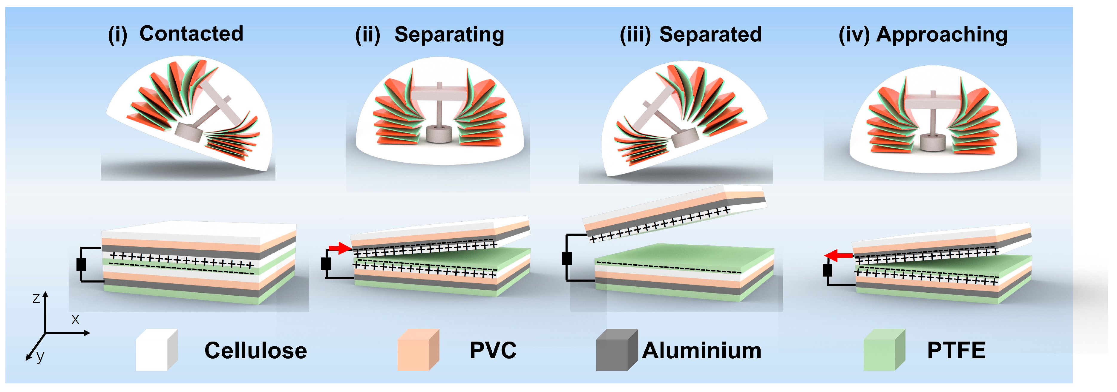
A detailed view of the second part, the swingable hammer, is shown in Figure 1c. Figure 1c (i) shows two components. The first component comprises a hammer head, stick, and tail sphere; the second component is a cylinder with a hollow center, slightly larger than the sphere in the first component. Figure 1c (ii) demonstrates that this hammer configuration allows 30° of swinging motion perpendicular to the XY plane, ensuring that the HSO-TENG can harvest energy in any direction. Figure 2 shows the working mechanism and charge distribution map during the slapping motion. Notably, the two strips in the SO-TENG are constructed as four-layer and five-layer structures, with the layers securely fixed using 1 cm wide double-sided tape. Here, polytetrafluoroethylene (PTFE) is selected as a material with favorable electron transfer properties. The use of soft PVC also increases the overall self-recovery of the SO-TENGs. Here, the two SO-TENGs along the y-axis are hidden, and only the two along the x-axis are visible. As observed, when the HSO-TENG exhibits a swinging motion around the y-axis, this movement causes the internal pendulum to compress and stretch the SO-TENGs arranged along the x-axis. The two strips of the SO-TENG on the right, for example, contact and separate with compression and stretching, leading to a charge exchange between the paper and PTFE. The SO structure ensures that both sides of the two strips are in contact. Therefore, charges can be effectively generated on both sides of the strips, optimizing the energy conversion capability of the device. Notably, the SO-TENGs demonstrate different left-handed and right-handed rotation states upon stretching, depending on the stacking directions [49]. Therefore, each set of SO-TENGs is designed as left-handed and right-handed structures to ensure symmetry.

3. Structure Optimization Based on Swinging Experiment

3.1. Experimental Setup of Swinging Experiment

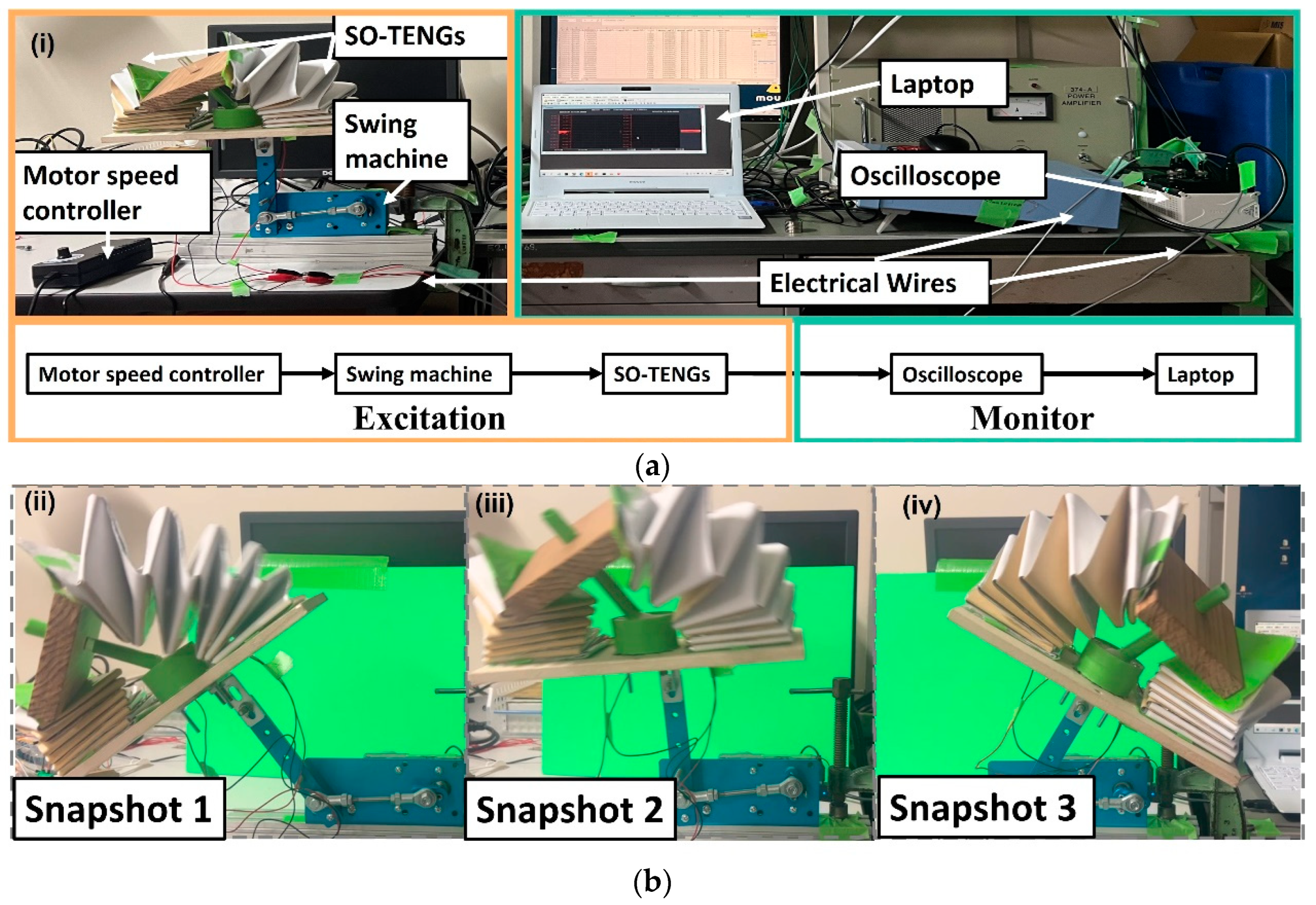
The effect of several parameters on the output voltage of the HSO-TENG is discussed in this section. The setup of the swinging experiment is displayed in Figure 3. As can be seen in this figure, the experiment setup can be divided into “excitation” and “monitor”. By adjusting the speed of the motor, the swing frequency is controlled. The swing machine can generate a low swing frequency between 0.275 and 1.45 Hz, which satisfies the low-frequency characteristics of ocean waves. To explore the relationship between the devices and wave environment, initially, the most simplified component in the HSO-TENG and two SO-TENG units connected to the swingable hammer are placed on the swing machine. Subsequently, the two SO-TENGs are stretched and compressed with the motion of the swingable hammer. During each swing experiment, three components (six SO-TENGs units) are tested more than three times to ensure consistent results. Figure 3b shows three snapshots of the movement of the SO-TENGs on the swing machine. Eventually, the two SO-TENGs are connected to the oscilloscope through separate wires, which enable real-time electrical power transmission. The output voltage is recorded and monitored on a laptop. The internal resistance of the oscilloscope is 1 mΩ.
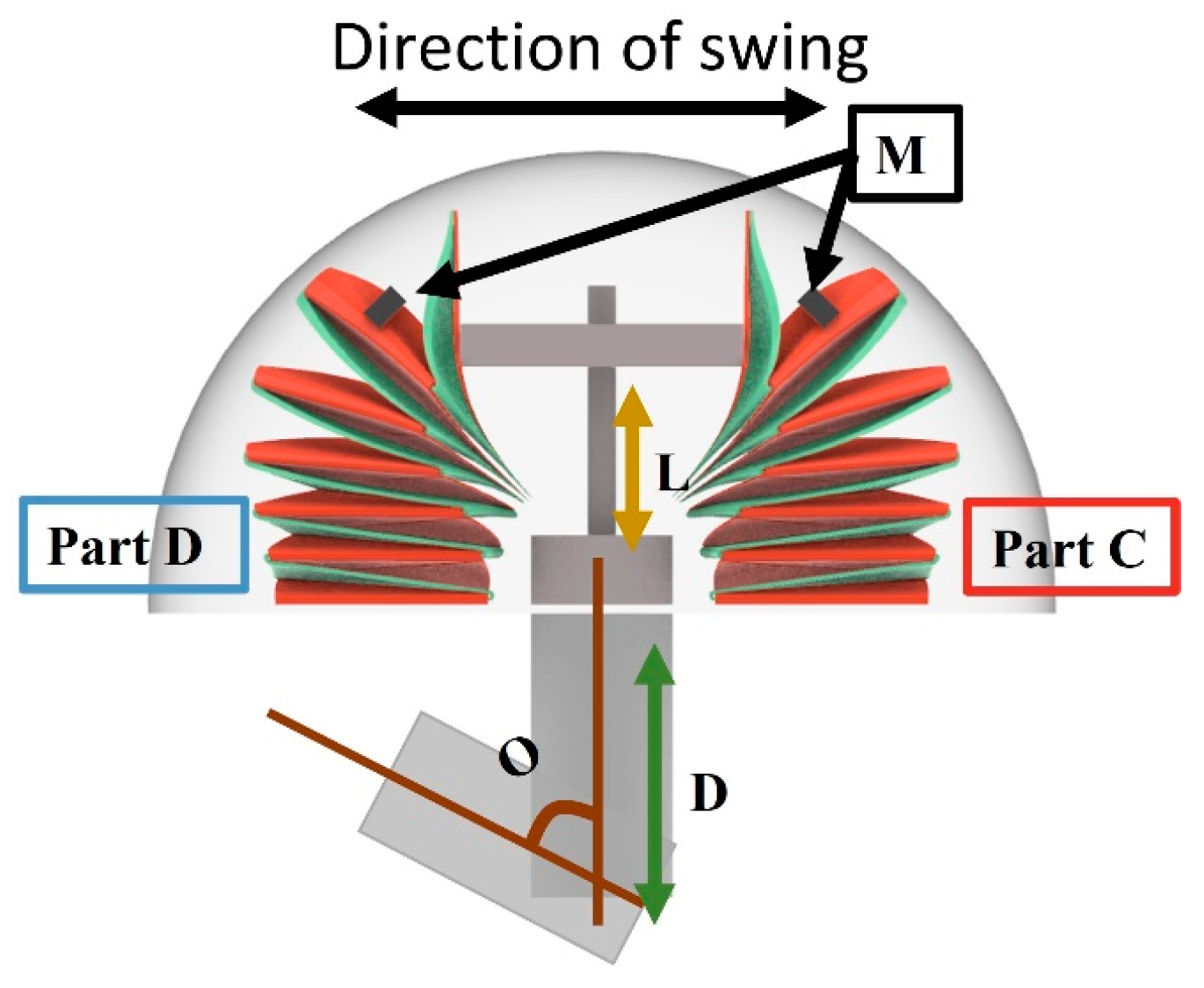
Figure 4 illustrates the parameters used for optimization, the results of which are further elaborated in Figure 5d–g. Here, O represents the maximum swing angle. The swing frequency and O represent the wave frequency and height, respectively. Next, we explore parameter M, which represents the weight of magnet mass to overcome the challenges associated with low frequency and high frictional forces. Furthermore, to increase the magnitude of the swing, the parameters L (the height of the hammer) and D (the length of the swing arm) are selected such that they increase the gravity center. Two symmetrical SO-TENGs, labeled Part C and Part D, are positioned along the swing direction and on either side of the hammer during the swinging experiment, which is used to simulate their performance along the wave direction.

3.2. Results and Discussion

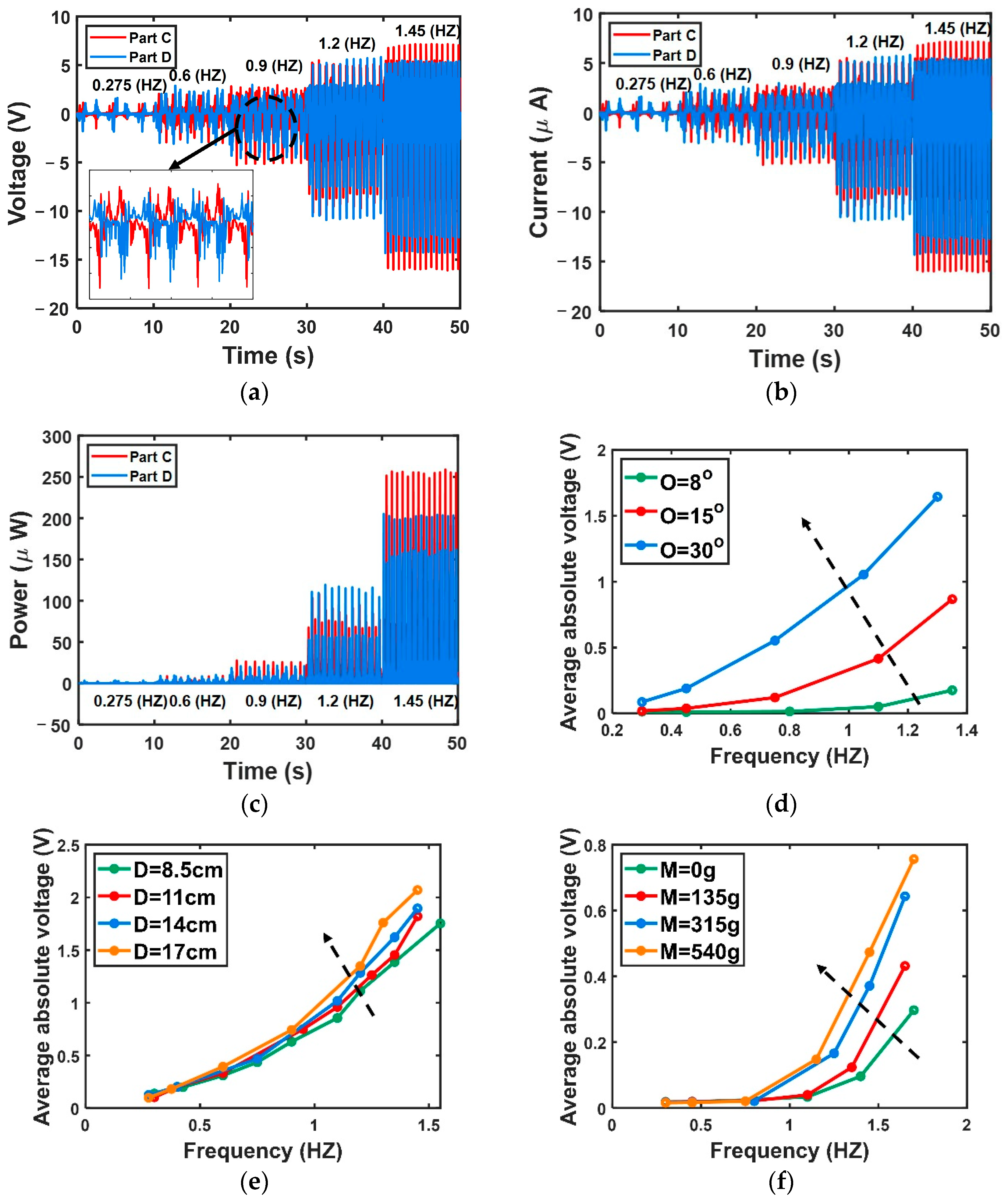
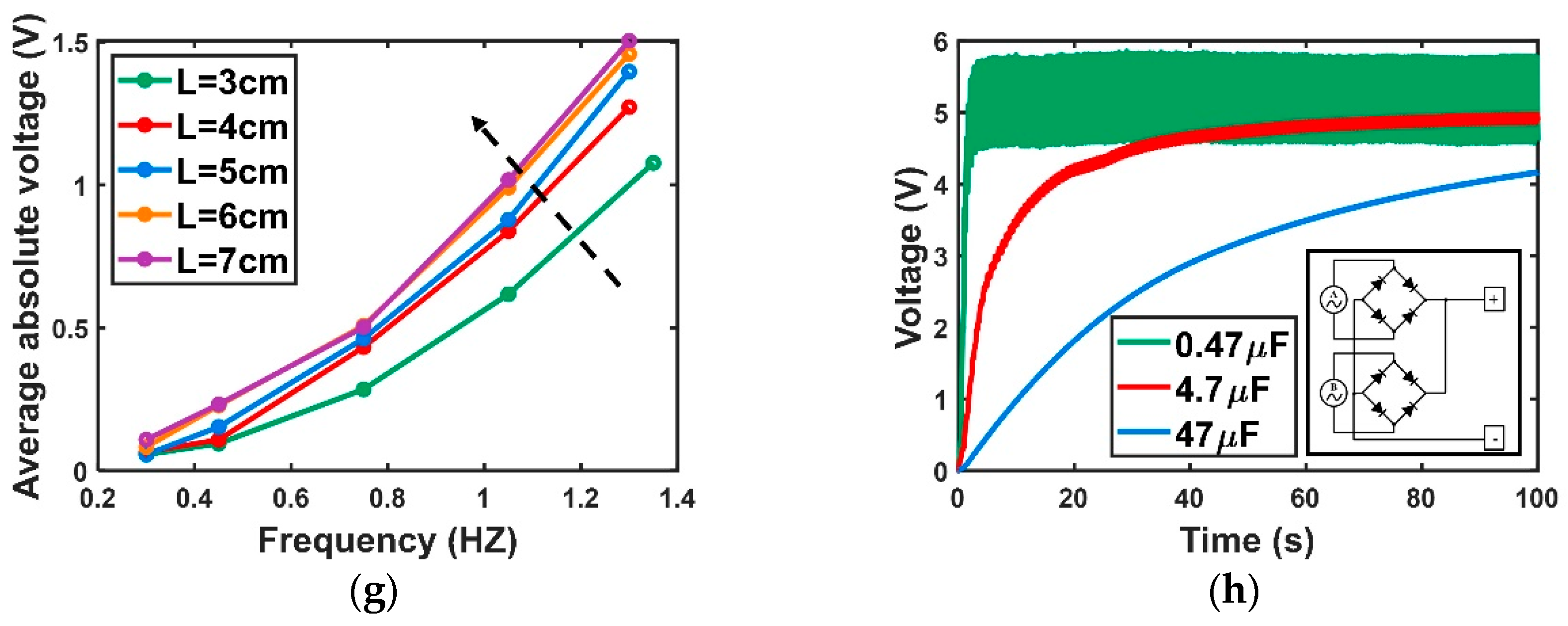
This section presents the filtered results. Figure 5a–c display the output voltage, current, and power versus time curve, respectively, covering a swinging frequency range of 0.275–1.45 Hz. The figures reveal that the two distinct waveforms of Parts C and D exhibit ordered and opposite voltage data, with their amplitudes increasing with increasing frequency. This trend demonstrates the remarkable sensitivity of the HSO-TENG to swing frequency. Figure 5d presents a plot of the absolute average voltage as a function of frequency for three maximum swing angles. Increasing the swing angle amplifies the output voltage. The two parameters shown in Figure 5a,d (swing frequency and maximum swing angle) can be associated with wave frequency and height, respectively, showcasing the HSO-TENG’s potential for wave monitoring applications. Therefore, in-depth investigations are conducted to investigate the influence of internal inertia using factors D and L. The impact of the external center of gravity is analyzed using factor M. Figure 5e–g demonstrate that enhancing D, M, and L can effectively enhance the power generation performance at a given frequency. Finally, the two SO-TENGs are rectified and connected in parallel on both sides of the capacitor to verify the possibility of powering other sensors. Figure 5h shows the circuit diagram. The charging curve illustrates that within 100 s, a 47 μF capacitor can be charged to 4 V, providing promising evidence of the HSO-TENG’s capacity to power additional sensors.

4. Performance of HSO-TENG in Experimental and Numerical Unidirectional Wave Tank

In this section, numerical models are built to find suitable fixed conditions for the HSO-TENG with respect to the monitoring of wave conditions. To validate the reliability of the numerical model, the experimental setup and results are introduced first (Figure 6).

4.1. Experimental Setup of Unidirectional Wave Tank

The HSO-TENG’s practicality is enhanced by incorporating an additional waterproof layer and selecting the optimal parameters mentioned in Section 3. This waterproof layer is a translucent spherical shell, slightly larger than the inner cover, which minimizes the risk of water accidentally entering the outermost spherical shell from the interior. Here, D, M, and L are 17 cm, 540 g, and 6 cm, respectively. L is not selected to be 7 cm to prevent the SO-TENG from touching the spherical shell and causing unnecessary friction interference.
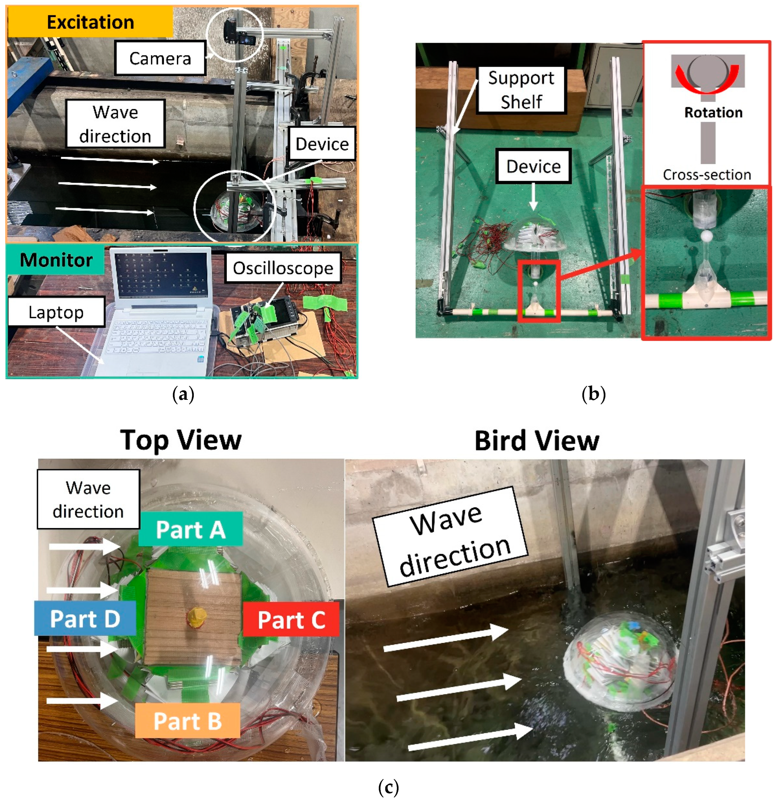
The overview of the experimental setup is divided into excitation and monitor parts. In the excitation part shown in Figure 6a, the HSO-TENG is positioned at the center of the wave tank, with its bottom close to the still water level. The parameters of the experimental wave tank are listed in Table 1. During the experiments, the HSO-TENG is connected to a support shelf. Figure 6b illustrates the connection between the HSO-TENG and support shelf, which employs the same swingable structure shown in Figure 1c. Furthermore, a camera is placed above the HSO-TENG to capture the motion of the device and compare it with the experimental results. When the HSO-TENG faces upstream and encounters incoming waves, the voltage generated by its four distinct SO-TENGs in Figure 6c (Part A‘, Part B‘, Part C‘, and Part D‘) is conveyed through four wires to an oscilloscope in the monitor part. Subsequently, a laptop (Figure 6a) is used for data analysis and monitoring.

4.2. Numerical Conditions in Unidirectional Wave Tank Based on SPH Method

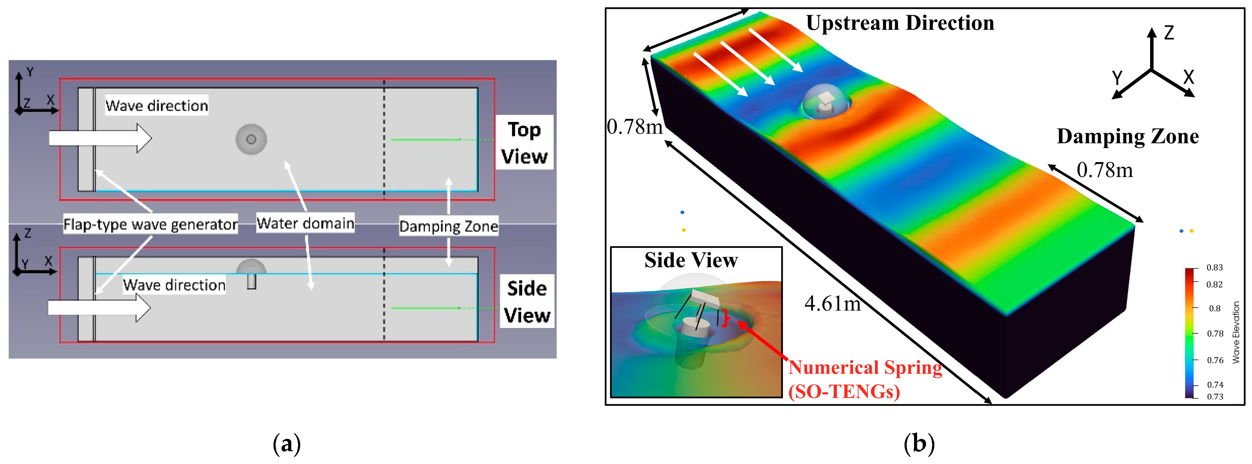
Next, the numerical deep-water wave tank is illustrated in Figure 7. Figure 7a shows the top and side views of the wave tank. The parameters of the wave tank are listed in Table 2. In particular, the flap-type wave generator, corresponding water depth, and damping zone are selected to replicate deep-water wave conditions. The numerical HSO-TENG is at the center of the unidirectional wave tank. Owing to the structural complexity of the SO-TENG, we use four simplified spring components to represent the SO-TENGs considering their elasticity properties, as shown in Figure 7b. An origami spring is typically fabricated using thin elastic plates rotating on straight-line hinges. Thus, the dominant source of the restoring force in the origami spring is primarily from the bending and twisting elasticity of the individual plates. The elastic responses of the origami spring were tested in a previous study [49].

4.3. Selection of Fixed Conditions Based on Numerical Model

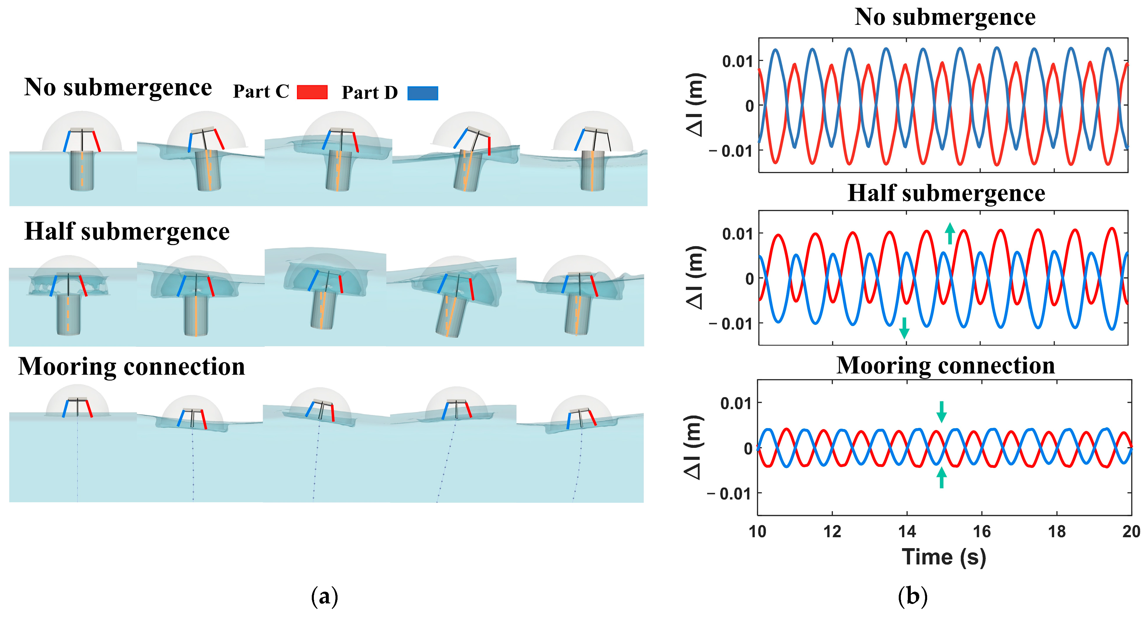
In this section, three typical boundary conditions (no submergence, half submergence, and mooring connection) are selected in the numerical model to find the most suitable one in Figure 8. In addition, the motions of the HSO-TENG in one period and the length change of the springs in 10 s are also shown alongside the three conditions. A comparison with the no submergence condition reveals that under the half submergence condition, the HSO-TENG swings toward the streamwise direction, resulting in insufficient compression of Part C and tension of Part D. Furthermore, the mooring connection condition shows that the HSO-TENG follows the wave, leading to a considerable reduction in the compression and stretching range of the internal spring, accounting for only half of the range observed under the no submergence condition. Therefore, the no submergence condition is selected for subsequent experiments.

4.4. Validation of Numerical Model

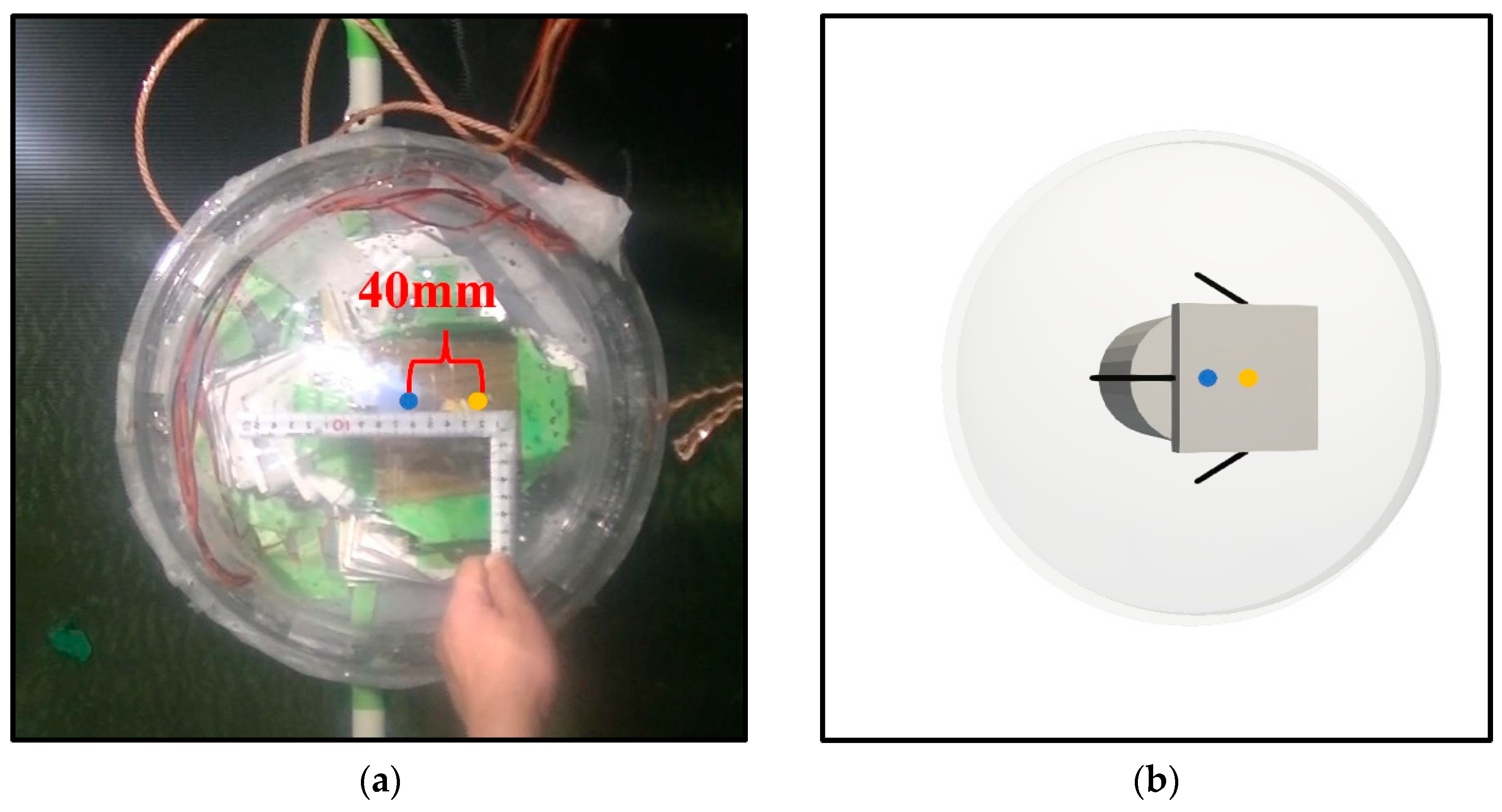
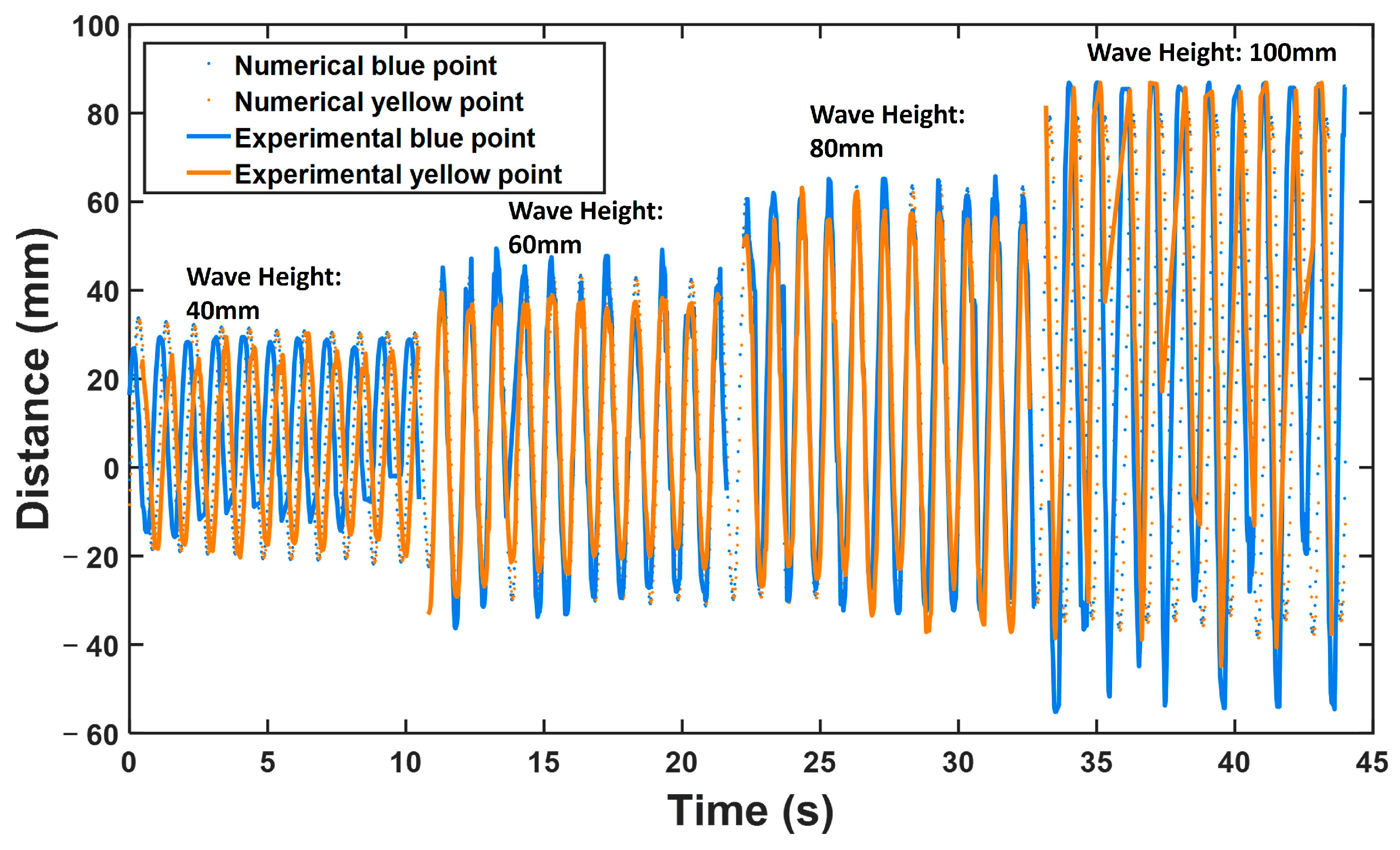
This section presents a comparison of the numerical motion of the HSO-TENG under the no submergence fixed condition with the experimental motion. To capture and compare the HSO-TENG’s motion in experimental and numerical results, the trajectories of two points, the top point of the hemisphere (indicated by the blue point) and the hammer (indicated by the yellow point), are recorded, which are shown in Figure 9a,b. In the experiment, the camera shown in Figure 6a records a top-view video. The motion trajectories of the two points are extracted from the recorded videos through an image recognition program. The distance of the blue and yellow points’ movement in the experiment can be calculated using the measured-distance-to-pixel ratio.
Figure 10 shows a comparison of the experimental and numerical distances to the respective reference line in the streamwise direction. Blue and yellow points exhibit good agreement between the experimental and numerical results, indicating the reliability of the numerical model.
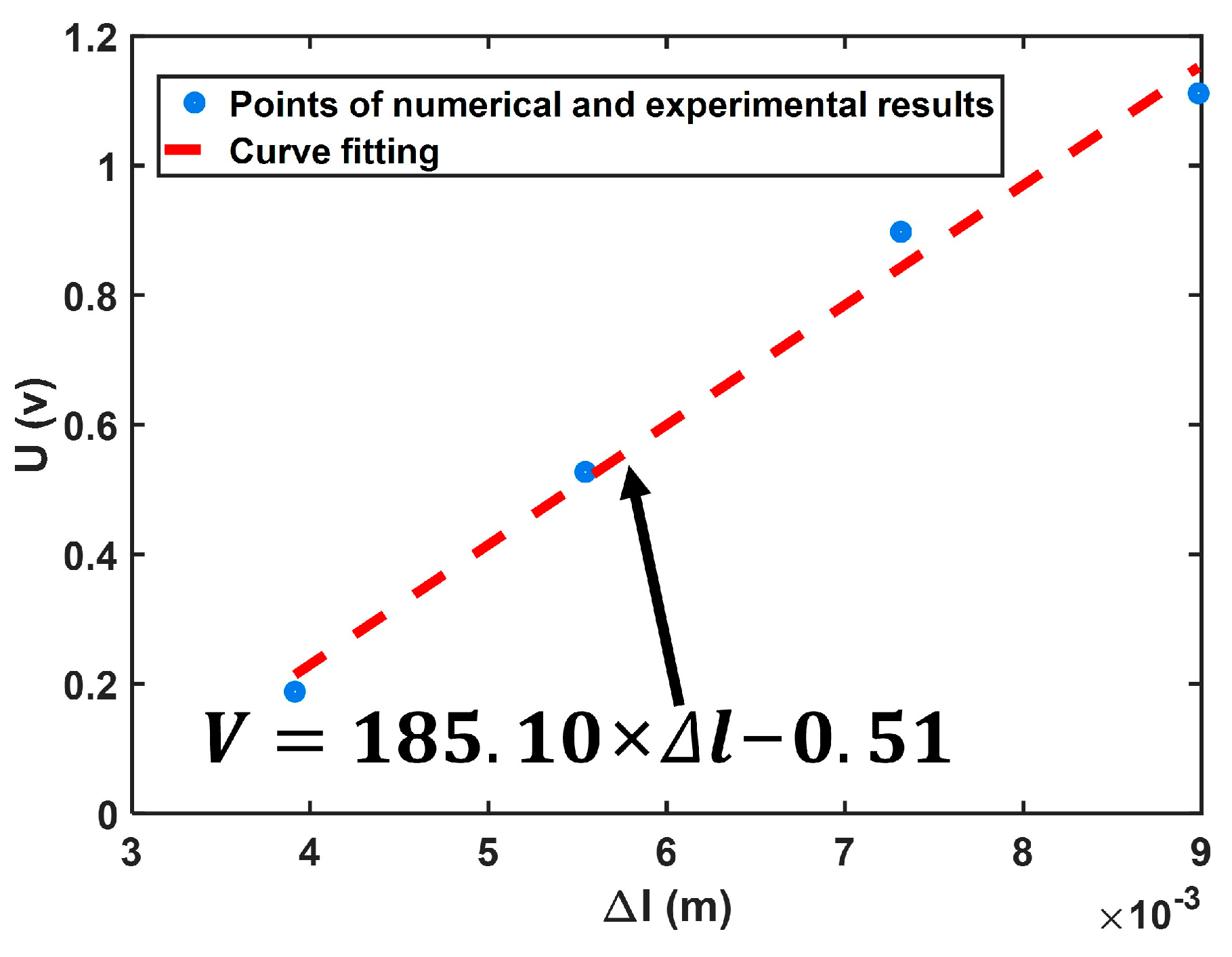
From the perspective of electrical performance, a correlation exists between voltage and the distance between two contact plates, according to the V–Q–x model of vertical-contact TENGs [50]. The SO-TENG comprises many plates that contact each other; therefore, the sum of their distances is the length (Δl). Thus, the voltage generated by the SO-TENG parts can be predicted based on the length of the SO-TENG. The relationship between the numerical average changes in length and the experimental average voltage is depicted in Figure 11; a linear relationship is obtained via curve fitting.

4.5. Experimental Results and Discussion

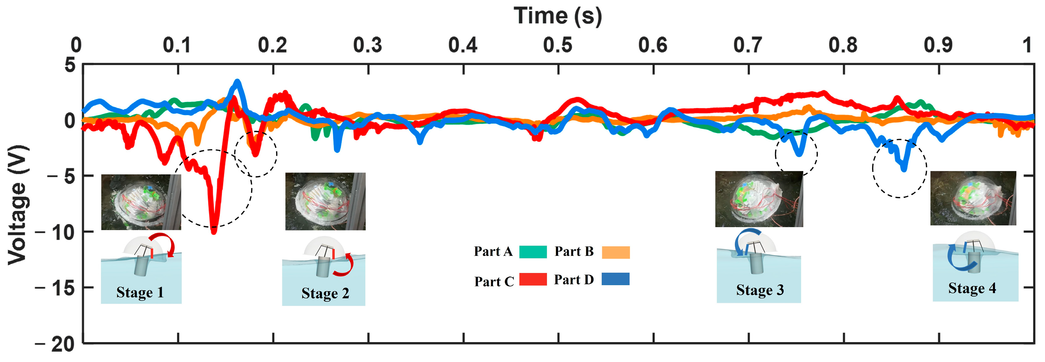
In this section, the response of the HSO-TENG to wave parameters and the performance of the power supply to the sensors are discussed. Owing to inherent differences between liquid–solid coupling and swing machine simulations, a comprehensive comparison of the output voltage and motion of the HSO-TENG with a double-swing structure in the wave tank is presented and analyzed in Figure 12. Throughout the process, from the wave trough to the crest, the HSO-TENG deflects toward the downstream direction, concurrently compressing Part C and stretching Part D. This motion results in the voltage curve displaying a prominent negative peak (stage 1). Subsequently, as the HSO-TENG proceeds past the wave crest, the wave’s influence causes the hemisphere to swing toward a horizontal position. This swing exerts pressure on Part C between the pendulum and bottom plate, inducing a minor wave peak (stage 2). Subsequently, as the HSO-TENG passes from the wave crest to the trough, it deflects toward the upstream direction, resulting in a small negative peak in the voltage curve of Part D (stage 3). After passing through the trough, the HSO-TENG returns to a horizontal position, compressing Part D (stage 4). Notably, the large peaks occur during stages 1 and 4, as the wave crest accumulates more force than the pull-back force experienced during the trough. This observation allows us to effectively discern the direction of the wave through the output curve of the HSO-TENG. In addition, Parts A and B generate voltage along the spanwise direction. This enables the HSO-TENG to generate complementary voltage outputs regardless of the direction the HSO-TENG faces the waves, which is conducive to a stable power supply.
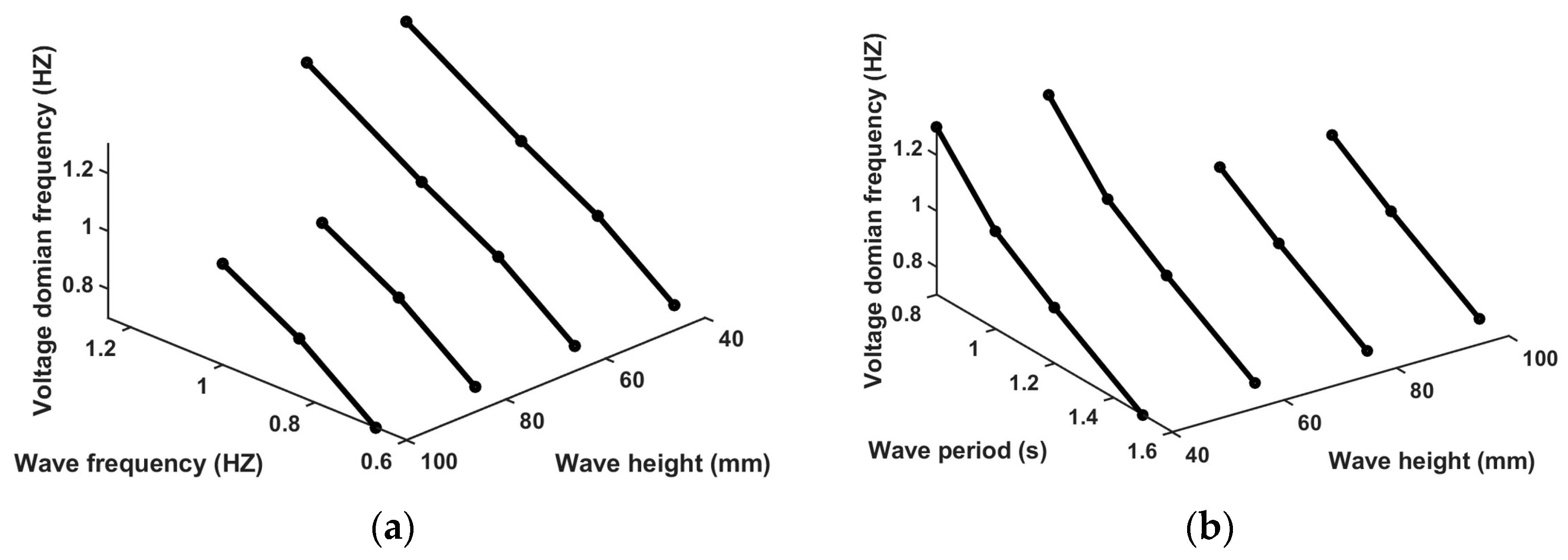
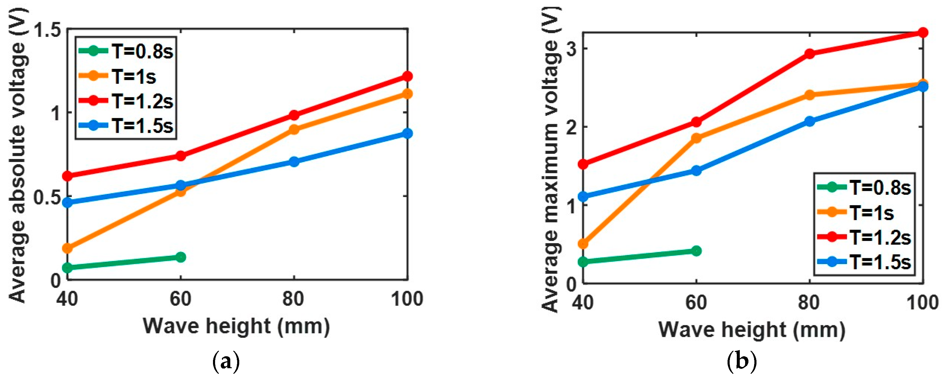
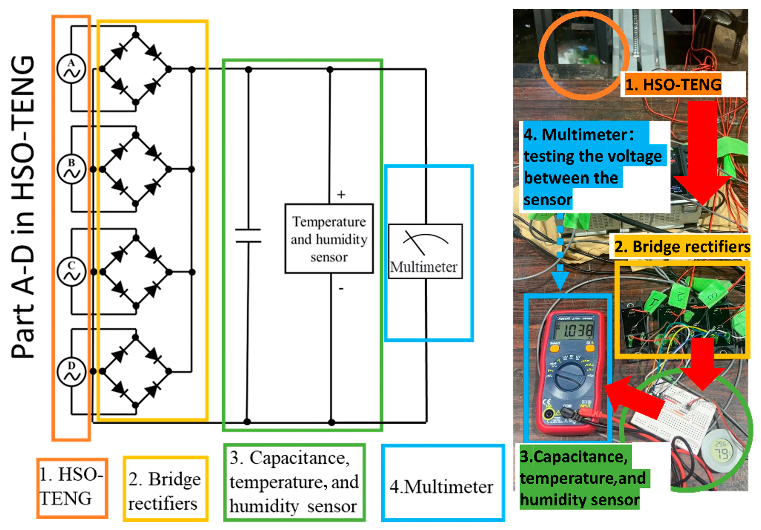
In Figure 13a,b, for different wave heights, clear linear relationships are depicted between voltage domain frequencies, wave frequencies, and wave periods, which serve as a fundamental basis for predicting the wave period. Figure 14a,b show the linear relationship between average absolute voltage, average maximum voltage, and different wave heights. This relationship demonstrates the feasibility of using these two voltage parameters to obtain wave height. Finally, the sensor test is conducted, as shown in Figure 15. The left image is the circuit diagram, and the right image is the experimental operation diagram. The four colored boxes in the left image, orange, yellow, green, and blue, correspond to the devices in the four colored circles shown in the right image, namely “HSO-TENG”, “Bridge rectifiers”, “Capacitance, temperature, and humidity sensor”, and “Multimeter”. First, as shown in the orange box, the four SO-TENG parts in one HSO-TENG are interconnected in parallel. Furthermore, they are connected to the rectifier circuit in the yellow box. Next, they charge the temperature and humidity sensor by connecting to a 47-μF capacitor in the green box. When the wave height is 100 mm and the wave period is 1 s, the sensor with a power of 0.15 mW can work continuously. Using the multimeter (blue box) connected in parallel to the sensor, the voltage can be found to be stable between 0.9 and 1 V. This continuous operation of the sensor effectively demonstrates the potential that the HSO-TENG can function as a power supply for other sensors.

5. Numerical Simulation in Multidirectional Circular Wave Tank

5.1. Introduction of Numerical Multidirectional Circular Wave Tank

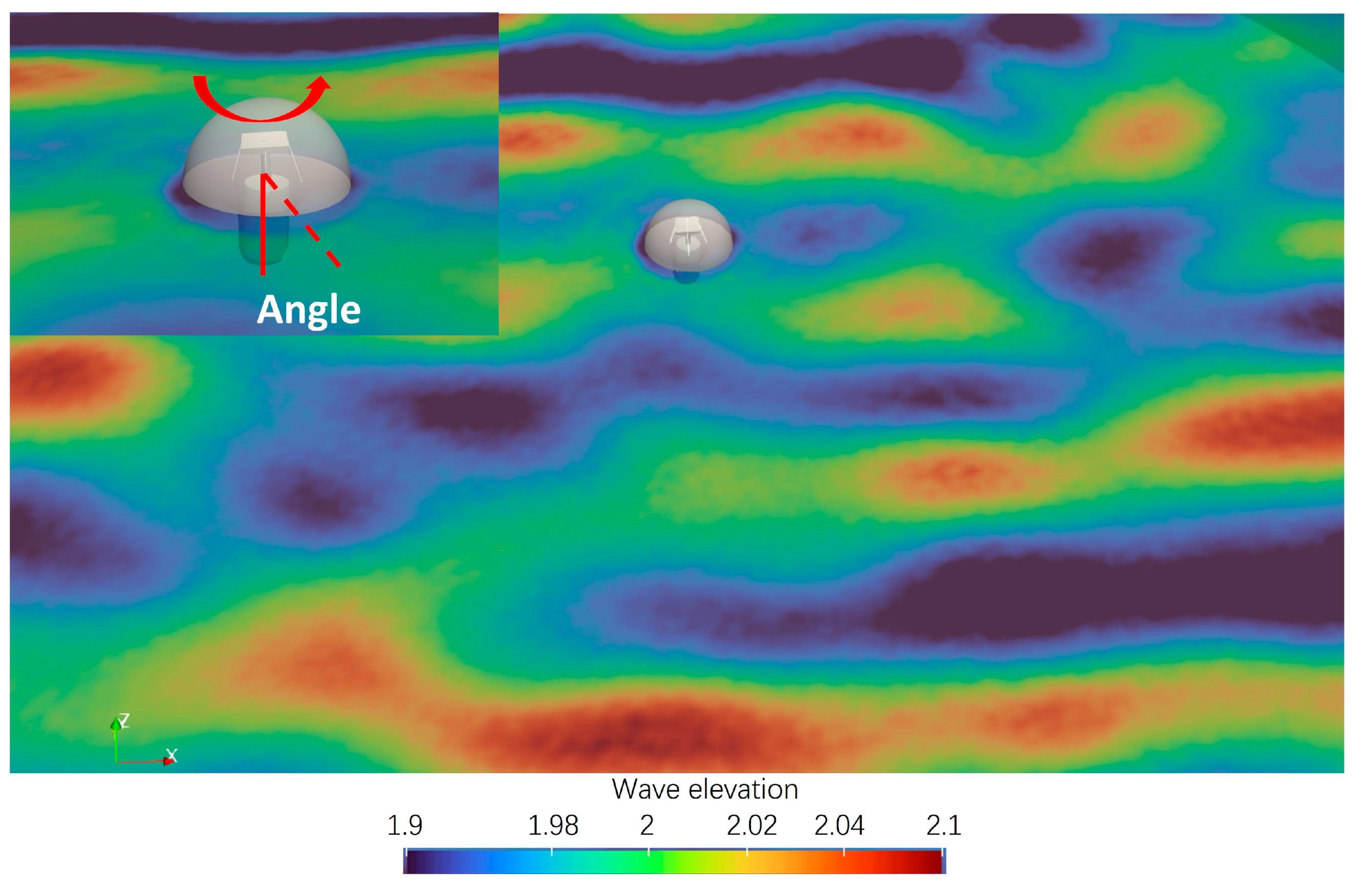
Simulations within a circular numerical wave tank are conducted to thoroughly investigate the operational characteristics of the HSO-TENG when subjected to multidirectional waves. The numerical circular wave tank is built in the open-source program DualSPHysics [51]. As shown in Figure 16, the numerical model of HSO-TENG is placed at the center of the numerical circular wave tank, surrounded by 168 wave generators. Thus, a multidirectional wave can be generated. The reliability of this numerical circular wave tank has been validated using the FloWave tank at the University of Edinburgh, with comprehensive details reported in a previous study [44]. The parameters of the numerical wave tank and HSO-TENG used in this study are listed in Table 3. Within this numerical wave tank, the HSO-TENG with four spreading parameters (s = 5, 10, 25, and infinity (inf)) and four mean wave direction angles (angle = 0°, 15°, 30°, and 45°) are tested (Section 5.2).

5.2. Numerical Results in Sensing Wave Directions and Parameters

In this section, the fitting equation shown in Figure 11 is used to estimate the output voltage via numerical average changes in the spring length during the multidirectional wave tank simulation (Figure 17 and Figure 18).
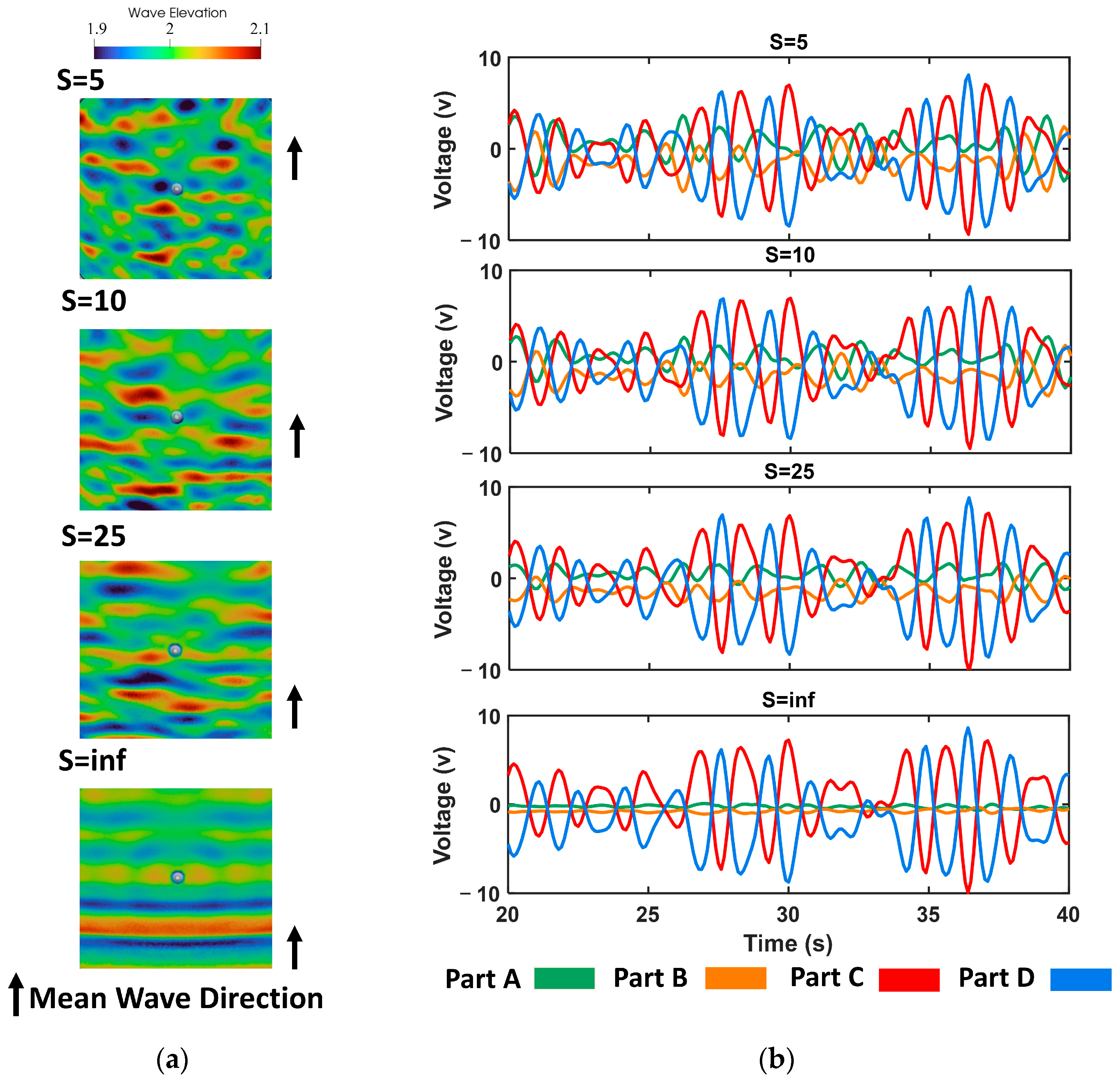
Firstly, four distinct spreading parameters, denoted as s, were selected: namely, s = 5, 10, 25, and inf. Here, the mean wave direction angle is set as 0°. In Figure 17, the short-crested wave fields diminish with increasing s values, and only long-crested waves are observed as s approaches infinity. The HSO-TENG is placed at the center of the wave tank, while the spring modules representing four SO-TENG parts are recorded. The voltage is calculated based on the length of the SO-TENG ( Δ l ) and the equation presented in Figure 11. Importantly, the amplitude of the voltage fluctuations of Parts A and B is high when s = 5, diminishing progressively as s decreases. When s equals inf, the fluctuation of Parts A and B virtually dissipates.
Next, the performance of testing wave directions is assessed. Four mean wave direction angles (angle = 0°, 15°, 30°, and 45°) are explored considering the symmetry of the HSO-TENG. Here, the spreading parameter is set as 5. As shown in Figure 18, green, yellow, red, and blue represent the four SO-TENGS. The voltage exhibits clear differences at the four angles. In particular, when the angle increases before reaching 45°, the Δ l of all the parts increases. When it equals 45°, all the parts have the same amplitudes. Here, the changes in the length of the SO-TENG ( Δ l ) with different spreading parameters are compared. Evidently, Parts C and D, which are arrayed along the mean wave direction, exhibit more pronounced amplitude in voltage fluctuations compared with Parts A and B, which are arrayed perpendicular to the mean wave direction.
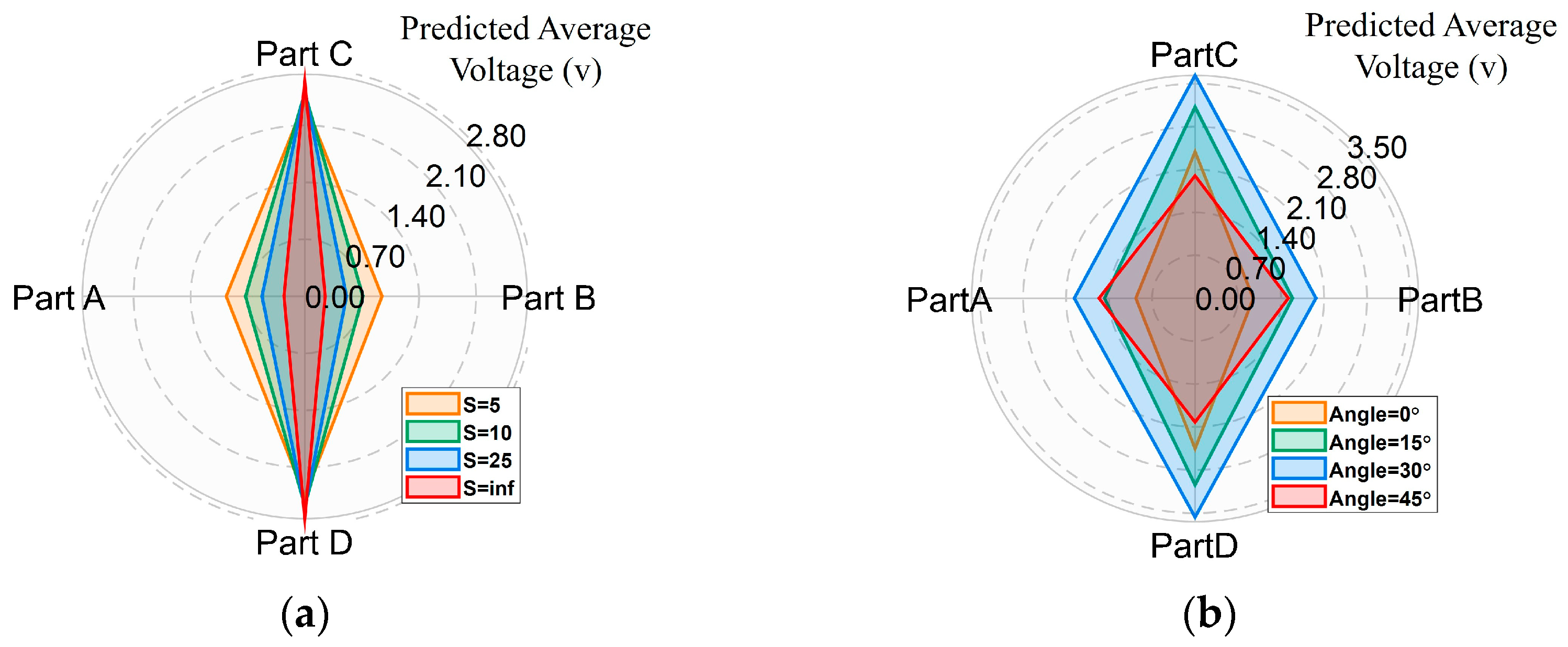
Thus, the predicted average voltages of the four SO-TENG parts with different s and angles are shown in Figure 19a and Figure 19b, respectively. These results demonstrate the feasibility of employing the HSO-TENG to monitor tiny wave direction changes and ocean wave spreading parameters using the output voltage of each SO-TENG part. In addition, based on voltage calculations derived from experiments and prediction models, the average power of an HSO-TENG device ranges from 2 to 31 μW, and the maximum power ranges from 4 to 1 μW. Thus, one or more devices can charge a capacitor and supply power to small sensors or equipment, including lighting, temperature and humidity sensors, oxygen, and wind speed sensors, to monitor the marine environment.

6. Conclusions

In summary, the HSO-TENG proposed in this study achieves good power generation and wave monitoring functions after a series of optimizations. The main findings summarized as follows:
From the perspective of the internal inertia and overall centroid of gravity, three structural parameters, the weight of magnet mass, the height of the hammer, and the length of the external swing arm, are found to increase the average voltage generation by 33%, 62%, and 50%, respectively.
The no submergence condition that fully compresses and stretches SO-TENGs is selected from three fixed conditions through a numerical model comparison analysis.
The optimized HSO-TENG under large-scale wave tank experiments and a numerical circular wave tank exhibits a good response to the wave height, wave period, wave frequency, direction, and wave spreading parameters based on the output voltage.
The maximum voltage can reach 15 V. When the four SO-TENGs are connected in parallel, the output voltage can continually supply power to a temperature and humidity sensor.
The SPH method can simulate the motion of HSO-TENGs and similar wave energy harvesting devices, thereby guiding device design and predicting performance.
Therefore, the HSO-TENG demonstrates efficient sensor capabilities, accurately responds to wave parameters, and simultaneously serves as an energy supply source for other sensors. In addition, the optimized methods can be applied to coupling similar self-powered ocean monitoring devices with ocean waves.
In future research, tests will be conducted on the HSO-TENG in real sea areas to further validate the numerical model. In addition, the method for estimating electric power based on experiments and numerical results will be further developed.

Author Contributions

Conceptualization, X.D., H.Z., H.C. and Z.H.; methodology, X.D., H.Z., H.C. and Z.H.; software, X.D.; validation, X.D. and H.Z.; formal analysis, X.D.; investigation, X.D., H.Z., H.C. and Z.H.; resources, T.N., Y.T., P.J. and H.M.; data curation, X.D.; writing—original draft preparation, X.D.; writing—review and editing, X.D.; visualization, X.D.; supervision, T.N., Y.T., P.J. and H.M. All authors have read and agreed to the published version of the manuscript.

Funding

This research received no external funding.

Data Availability Statement

Data are contained within the article.

Acknowledgments

This study is supported in part by the FY2022 JSPS Invitational Fellowships for Research in Japan (S22066). X.D. acknowledges the financial support of the China Scholarship Council (CSC202108050059). P.J. acknowledges the Startup Fund of the One-Hundred Talent Program at Zhejiang University. The authors thank Taiga Kanehira from Kyoto University, Samuel Draycott from The University of Manchester, and David Ingram from The University of Edinburgh for developing the numerical model for FloWave.

Conflicts of Interest

The authors declare no conflict of interest.

References

  1. McGranahan, G.; Balk, D.; Anderson, B. The rising tide: Assessing the risks of climate change and human settlements in low elevation coastal zones. Environ. Urban. 2007, 19, 17–37. [Google Scholar] [CrossRef]
  2. Melikoglu, M. Current status and future of ocean energy sources: A global review. Ocean Eng. 2018, 148, 563–573. [Google Scholar] [CrossRef]
  3. Ramos, A.; Rouboa, A. Life cycle thinking of plasma gasification as a waste-to-energy tool: Review on environmental, economic and social aspects. Renew. Sustain. Energy Rev. 2022, 153, 111762. [Google Scholar] [CrossRef]
  4. Small, C.; Nicholls, R.J. A global analysis of human settlement in coastal zones. J. Coast. Res. 2003, 19, 584–599. [Google Scholar]
  5. Bergsma, E.W.; Almar, R.; Anthony, E.J.; Garlan, T.; Kestenare, E. Wave variability along the world’s continental shelves and coasts: Monitoring opportunities from satellite Earth observation. Adv. Space Res. 2022, 69, 3236–3244. [Google Scholar] [CrossRef]
  6. Momber, A.; Wilms, M.; Brün, D. The use of meteorological and oceanographic sensor data in the German offshore territory for the corrosion monitoring of marine structures. Ocean Eng. 2022, 257, 110994. [Google Scholar] [CrossRef]
  7. Cao, H.; Wu, X.; Wu, H.; Pan, Y.; Luo, D.; Azam, A.; Zhang, Z. A hybrid self-powered system based on wind energy harvesting for low-power sensors on canyon bridges. Int. J. Precis. Eng. Manuf.-Green Technol. 2023, 10, 167–192. [Google Scholar] [CrossRef]
  8. Cao, H.; Zeng, X.; Wu, L.; Wu, X.; Zhang, Z. A hybrid wind and rainwater energy harvesting system for applications in sea-crossing bridges. Ocean Eng. 2021, 234, 109267. [Google Scholar] [CrossRef]
  9. Xu, G.; Shi, Y.; Sun, X.; Shen, W. Internet of things in marine environment monitoring: A review. Sensors 2019, 19, 1711. [Google Scholar] [CrossRef]
  10. Yang, H.; Liang, X.; Kan, J.; Wang, Z.L.; Jiang, T.; Hong, Z. Triboelectric nanogenerator integrated with a simple controlled switch for regularized water wave energy harvesting. Nano Res. 2024, 1–8. [Google Scholar] [CrossRef]
  11. Yu, Y.; Li, H.; Zhao, D.; Gao, Q.; Li, X.; Wang, J.; Wang, Z.L.; Cheng, T. Material’s selection rules for high performance triboelectric nanogenerators. Mater. Today 2023, 64, 61–71. [Google Scholar] [CrossRef]
  12. Zhang, B.; Gao, Q.; Li, W.; Zhu, M.; Li, H.; Cheng, T.; Wang, Z.L. Alternating Magnetic Field-Enhanced Triboelectric Nanogenerator for Low-Speed Flow Energy Harvesting. Adv. Funct. Mater. 2023, 33, 2304839. [Google Scholar] [CrossRef]
  13. Ni, W.; Tian, G.; Yang, C.; Yang, W.; Ma, Y.; Xu, L. Simultaneous energy utilization and vibration suppression study of a rolling-structured triboelectric nanogenerator for the vortex-induced vibration of a cylinder. Ocean Eng. 2023, 288, 115976. [Google Scholar] [CrossRef]
  14. Wardhana, E.M.; Mutsuda, H.; Tanaka, Y.; Nakashima, T.; Kanehira, T.; Maeda, S.; Yamauchi, M. Characteristics of electric performance and key factors of a hybrid piezo/triboelectric generator for wave energy harvesting. Sustain. Energy Technol. Assess. 2022, 50, 101757. [Google Scholar] [CrossRef]
  15. Wardhana, E.M.; Mutsuda, H.; Tanaka, Y.; Nakashima, T.; Kanehira, T.; Taniguchi, N.; Maeda, S.; Yonezawa, T.; Yamauchi, M. Harvesting contact-separation-compression vibrations using a flexible and compressible triboelectric generator. Sustain. Energy Technol. Assess. 2020, 42, 100869. [Google Scholar] [CrossRef]
  16. Wang, X.; Hu, Y.; Li, J.; Ma, J.; Wan, N.; Wen, J.; Cheng, T. A double-float structured triboelectric nanogenerator for wave hydrological monitoring. Sustain. Energy Technol. Assess. 2022, 54, 102824. [Google Scholar] [CrossRef]
  17. Jiao, P.; Nazar, A.M.; Egbe, K.J.I.; Rayegani, A. Magnetically circular layers triboelectric nanogenerators (MCL-TENG) for velocity sensing and damage detection. Sustain. Energy Technol. Assess. 2022, 53, 102644. [Google Scholar] [CrossRef]
  18. Ji, J.; Luo, Q.; Ye, K. Vibration control based metamaterials and origami structures: A state-of-the-art review. Mech. Syst. Signal Process. 2021, 161, 107945. [Google Scholar] [CrossRef]
  19. Huang, C.; Tan, T.; Wang, Z.; Zhang, S.; Yang, F.; Lin, Z.; Yan, Z. Origami dynamics based soft piezoelectric energy harvester for machine learning assisted self-powered gait biometric identification. Energy Convers. Manag. 2022, 263, 115720. [Google Scholar] [CrossRef]
  20. Lu, D.; Liu, T.; Meng, X.; Luo, B.; Yuan, J.; Liu, Y.; Zhang, S.; Cai, C.; Gao, C.; Wang, J.; et al. Wearable triboelectric visual sensors for tactile perception. Adv. Mater. 2023, 35, 2209117. [Google Scholar] [CrossRef]
  21. Tao, K.; Yi, H.; Yang, Y.; Tang, L.; Yang, Z.; Wu, J.; Chang, H.; Yuan, W. Miura-origami-inspired electret/triboelectric power generator for wearable energy harvesting with water-proof capability. Microsyst. Nanoeng. 2020, 6, 56. [Google Scholar] [CrossRef] [PubMed]
  22. Pang, Y.; Zhu, X.; Yu, Y.; Liu, S.; Chen, Y.; Feng, Y. Waterbomb-origami inspired triboelectric nanogenerator for smart pavement-integrated traffic monitoring. Nano Res. 2022, 15, 5450–5460. [Google Scholar] [CrossRef]
  23. Tao, K.; Yi, H.; Yang, Y.; Chang, H.; Wu, J.; Tang, L.; Yang, Z.; Wang, N.; Hu, L.; Fu, Y.; et al. Origami-inspired electret-based triboelectric generator for biomechanical and ocean wave energy harvesting. Nano Energy 2020, 67, 104197. [Google Scholar] [CrossRef]
  24. Xia, K.; Liu, J.; Li, W.; Jiao, P.; He, Z.; Wei, Y.; Qu, F.; Xu, Z.; Wang, L.; Ren, X.; et al. A self-powered bridge health monitoring system driven by elastic origami triboelectric nanogenerator. Nano Energy 2023, 105, 107974. [Google Scholar] [CrossRef]
  25. Gonçalves, I.; Rodrigues, C.; Ventura, J. Sea State Adaptation Enhances Power Output of Triboelectric Nanogenerators for Tailored Ocean Wave Energy Harvesting. Adv. Energy Mater. 2024, 14, 2302627. [Google Scholar] [CrossRef]
  26. Yang, S.; Zhang, C.; Du, Z.; Tu, Y.; Dai, X.; Huang, Y.; Fan, J.; Hong, Z.; Jiang, T.; Wang, Z.L. Fluid Oscillation-Driven Bi-Directional Air Turbine Triboelectric Nanogenerator for Ocean Wave Energy Harvesting. Adv. Energy Mater. 2024, 14, 2304184. [Google Scholar] [CrossRef]
  27. Gao, Q.; Xu, Y.; Yu, X.; Jing, Z.; Cheng, T.; Wang, Z.L. Gyroscope-structured triboelectric nanogenerator for harvesting multidirectional ocean wave energy. ACS Nano 2022, 16, 6781–6788. [Google Scholar] [CrossRef]
  28. Han, J.; Liu, Y.; Feng, Y.; Jiang, T.; Wang, Z.L. Achieving a Large Driving Force on Triboelectric Nanogenerator by Wave-Driven Linkage Mechanism for Harvesting Blue Energy toward Marine Environment Monitoring. Adv. Energy Mater. 2023, 13, 2203219. [Google Scholar] [CrossRef]
  29. Rui, P.; Zhang, W.; Zhong, Y.; Wei, X.; Guo, Y.; Shi, S.; Liao, Y.; Cheng, J.; Wang, P. High-performance cylindrical pendulum shaped triboelectric nanogenerators driven by water wave energy for full-automatic and self-powered wireless hydrological monitoring system. Nano Energy 2020, 74, 104937. [Google Scholar] [CrossRef]
  30. Blanke, M.; Jensen, A.G. Dynamic properties of a container vessel with low metacentric height. Trans. Inst. Meas. Control 1997, 19, 78–93. [Google Scholar] [CrossRef]
  31. Du, X.; Mutsuda, H.; Tanaka, Y.; Nakashima, T.; Kanehira, T.; Taniguchi, N.; Moriyama, Y. Experimental and numerical studies on working parameter selections of a piezoelectric-painted-based ocean energy harvester attached to fish aggregating devices. Energy Sustain. Dev. 2022, 71, 73–88. [Google Scholar] [CrossRef]
  32. Xu, Z.; Chen, L.; Zhang, Z.; Han, J.; Chen, P.; Hong, Z.; Jiang, T.; Wang, Z.L. Durable Roller-Based Swing-Structured Triboelectric Nanogenerator for Water Wave Energy Harvesting. Small 2023, 20, 2307288. [Google Scholar] [CrossRef] [PubMed]
  33. Bhatta, T.; Maharjan, P.; Shrestha, K.; Lee, S.; Salauddin, M.; Rahman, M.T.; Rana, S.S.; Sharma, S.; Park, C.; Yoon, S.H.; et al. A Hybrid Self-Powered Arbitrary Wave Motion Sensing System for Real-Time Wireless Marine Environment Monitoring Application. Adv. Energy Mater. 2022, 12, 2102460. [Google Scholar] [CrossRef]
  34. Zhang, C.; Liu, L.; Zhou, L.; Yin, X.; Wei, X.; Hu, Y.; Liu, Y.; Chen, S.; Wang, J.; Wang, Z.L. Self-powered sensor for quantifying ocean surface water waves based on triboelectric nanogenerator. Acs Nano 2020, 14, 7092–7100. [Google Scholar] [CrossRef] [PubMed]
  35. Kumar, R.; Goyal, A.K.; Massoud, Y. Performance optimization of contact-separation mode triboelectric nanogenerator using dielectric nanograting. Results Eng. 2024, 22, 102108. [Google Scholar] [CrossRef]
  36. Kumar, R.; Goyal, A.K.; Massoud, Y. Development of flexible high-performance PDMS-based triboelectric nanogenerator using nanogratings. J. Colloid Interface Sci. 2024, 669, 458–465. [Google Scholar] [CrossRef] [PubMed]
  37. Du, X.; Mutsuda, H.; Wasada, Y.; Nakashima, T. Hybrid simulation of dissipative particle dynamics and computational fluid dynamics for friction drag reduction of polymer coatings. Ocean Eng. 2023, 285, 115415. [Google Scholar] [CrossRef]
  38. Lu, S.; Cheng, X.; Liu, J.; Li, S.; Yasukawa, H. Maneuvering modeling of a twin-propeller twin-rudder inland container vessel based on integrated CFD and empirical methods. Appl. Ocean Res. 2022, 126, 103261. [Google Scholar] [CrossRef]
  39. Lu, S.; Liu, J.; Hekkenberg, R. Mesh Properties for RANS Simulations of Airfoil-Shaped Profiles: A Case Study of Rudder Hydrodynamics. J. Mar. Sci. Eng. 2021, 9, 1062. [Google Scholar] [CrossRef]
  40. Wang, Y.; Pham, A.T.T.; Han, X.; Du, D.; Tang, Y. Design and evaluate the wave driven-triboelectric nanogenerator under external wave parameters: Experiment and simulation. Nano Energy 2022, 93, 106844. [Google Scholar] [CrossRef]
  41. Yan, Y.; Zhu, J.; Zhang, Y.; Wang, Z.; Jiang, L.; Wang, Z.L.; Zhu, J.; Cheng, T. Triboelectric-electromagnetic hybrid generator with swing-blade structures for effectively harvesting distributed wind energy in urban environments. Nano Res. 2023, 16, 11621–11629. [Google Scholar] [CrossRef]
  42. Zhu, M.; Zhang, J.; Wang, Z.; Yu, X.; Zhang, Y.; Zhu, J.; Wang, Z.L.; Cheng, T. Double-blade structured triboelectric–electromagnetic hybrid generator with aerodynamic enhancement for breeze energy harvesting. Appl. Energy 2022, 326, 119970. [Google Scholar] [CrossRef]
  43. Han, X.; Dong, S. Interaction of solitary wave with submerged breakwater by smoothed particle hydrodynamics. Ocean Eng. 2020, 216, 108108. [Google Scholar] [CrossRef]
  44. Kanehira, T.; Mutsuda, H.; Draycott, S.; Taniguchi, N.; Nakashima, T.; Doi, Y.; Ingram, D. Numerical re-creation of multi-directional waves in a circular basin using a particle based method. Ocean Eng. 2020, 209, 107446. [Google Scholar] [CrossRef]
  45. Quartier, N.; Ropero-Giralda, P.; Domínguez, J.M.; Stratigaki, V.; Troch, P. Influence of the drag force on the average absorbed power of heaving wave energy converters using smoothed particle hydrodynamics. Water 2021, 13, 384. [Google Scholar] [CrossRef]
  46. Shadloo, M.S.; Oger, G.; Le Touzé, D. Smoothed particle hydrodynamics method for fluid flows, towards industrial applications: Motivations, current state, and challenges. Comput. Fluids 2016, 136, 11–34. [Google Scholar] [CrossRef]
  47. Marrone, S.; Colagrossi, A.; Baudry, V.; Le Touzé, D. Extreme wave impacts on a wave energy converter: Load prediction through a SPH model. Coast. Eng. J. 2019, 61, 63–77. [Google Scholar] [CrossRef]
  48. Quartier, N.; Crespo, A.J.; Domínguez, J.M.; Stratigaki, V.; Troch, P. Efficient response of an onshore Oscillating Water Column Wave Energy Converter using a one-phase SPH model coupled with a multiphysics library. Appl. Ocean Res. 2021, 115, 102856. [Google Scholar] [CrossRef]
  49. Yoneda, T.; Matsumoto, D.; Wada, H. Structure, design, and mechanics of a paper spring. Phys. Rev. E 2019, 100, 013003. [Google Scholar] [CrossRef]
  50. Niu, S.; Wang, S.; Lin, L.; Liu, Y.; Zhou, Y.S.; Hu, Y.; Wang, Z.L. Theoretical study of contact-mode triboelectric nanogenerators as an effective power source. Energy Environ. Sci. 2013, 6, 3576–3583. [Google Scholar] [CrossRef]
  51. Domínguez, J.M.; Fourtakas, G.; Altomare, C.; Canelas, R.B.; Tafuni, A.; García-Feal, O.; Martínez-Estévez, I.; Mokos, A.; Vacondio, R.; Crespo, A.J.; et al. DualSPHysics: From fluid dynamics to multiphysics problems. Comput. Part. Mech. 2022, 9, 867–895. [Google Scholar] [CrossRef]
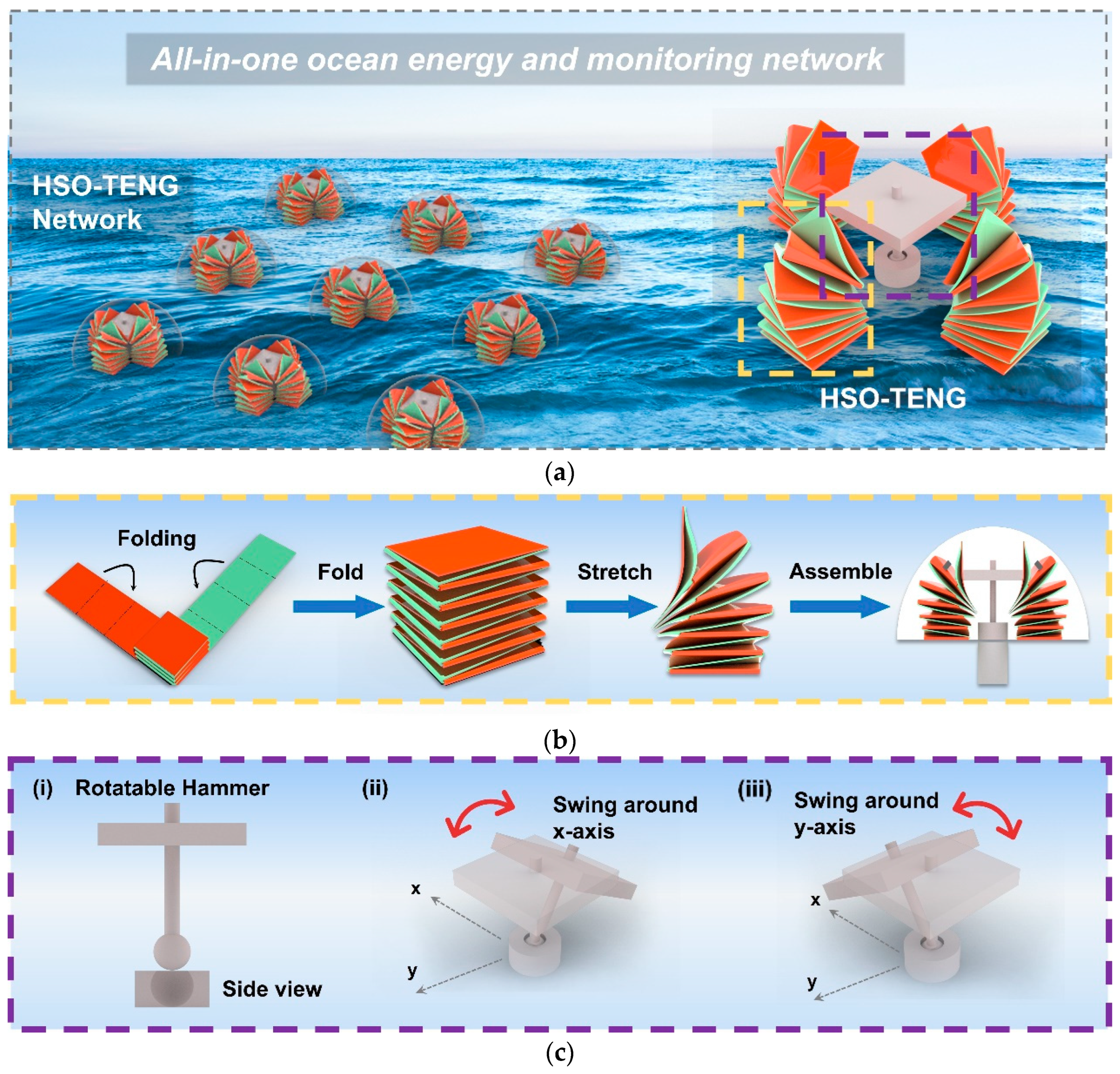
Figure 1. Structures and operation of HSO-TENG. (a) Schematic of HSO-TENG array in the ocean and the distribution of components in a disassembled HSO-TENG. (b) Schematic of the preparation process of SO-TENG. (c) Structure and working mechanism of the swingable hammer. ((i) Side view of the rotatable hammer, (ii) schematic diagram of a hammer swinging around the x-axis, (iii) schematic diagram of a hammer swinging around the y-axis).
Energies 17 02981 g001
Figure 2. Working mechanism, charge distribution map, and fabrication of the SO-TENG: the width and length of the strips are 7.5 and 100 cm, respectively; the basis weight of the paper is 104 g/m2, the thickness of the PVC is 0.25 mm, the thickness of the aluminum tape is 0.08 mm, and the thickness of the PTFE is 0.1 mm; they are connected with 15 mm wide double-sided tape. ((i) contacted state, (ii) separating state, (iii) separated state, (iv) approaching state).
Energies 17 02981 g002
Figure 3. Swinging experimental setup, flow chart, and three snapshots during experiments. (a) Swinging experimental setup. (b) Three snapshots during experiments. ((i) Contacted state, (ii) separating state, (iii) separated state, (iv) approaching state).
Energies 17 02981 g003
Figure 4. Schematic of parameters selected for optimization (SO-TENGs, Part C, and Part D are positioned along the swing direction).
Energies 17 02981 g004
Figure 5. Power generation performance of the HSO-TENG under different parameters. (a) Output voltage versus time curve under different swinging frequencies. (b) Current versus time curve under different swinging frequencies. (c) Power versus time curve under different swinging frequencies. (d) Absolute average voltage versus frequencies under varying maximum swing angles (D = 8.5 cm, M = 540 g, and L = 7 m). (e) Absolute average voltage versus frequencies under varying swing arm lengths (O = 30°, M = 540 g, and L = 7 m). (f) Absolute average voltage versus frequencies under varying weights of magnet mass (O = 15°, D = 14 cm, and L = 7 m). (g) Absolute average voltage versus frequencies under varying heights of the hammer (O = 30°, D = 14 cm, and M = 540 g). (h) Charging curves using different capacitances.
Energies 17 02981 g005aEnergies 17 02981 g005b
Figure 6. Experimental setup in the unidirectional wave tank. (a) Overview of the experimental unidirectional wave tank. (b) The connection part between the device and support shelf. (c) Illustration of four parts in an HSO-TENG device and its working details in the wave tank. (Parts C and D stretch and compress along the direction of the wave, while Parts A and B move perpendicular to the direction of the wave).
Energies 17 02981 g006
Figure 7. A schematic showing the numerical unidirectional wave tank and the HSO-TENG: (a) top and side views of the numerical wave tank (including a flap-type generator, water domain, and damping zone); (b) bird view of the numerical wave tank and side view of the HSO-TENG.
Energies 17 02981 g007
Figure 8. Comparison between the motions of the HSO-TENG and the change in length ( Δ l ) of the springs under three fixed conditions. (No submergence: the bottom of the hemisphere is flush with the horizontal level, and the entire device can swing around the fixed bottom of the cylinder. Half submergence: half of the hemisphere is submerged in water, and the entire device can swing around the fixed bottom of the cylinder. Mooring connection: the bottom of the hemisphere is flush with the horizontal level, and its bottom is connected to the bottom of the wave tank through mooring). (a) Comparison between the numerical motion of the HSO-TENG under the three fixed conditions. (b) Comparison between the change in the length (Δl) of the springs under the three fixed conditions.
Energies 17 02981 g008
Figure 9. Validation points in experiment and numerical simulation. (a) Validation points in experiment. (b) Validation points in numerical simulation.
Energies 17 02981 g009
Figure 10. Comparison between the experimental and numerical moving distance of HSO-TENG.
Energies 17 02981 g010
Figure 11. Relationship between numerical average changes in length and experimental average voltage (U: experimental average voltage (v) and Δ l : numerical average changes in length of numerical spring in Figure 7b).
Energies 17 02981 g011
Figure 12. Four stages of output voltage and motion of HSO-TENG in one experimental wave period.
Energies 17 02981 g012
Figure 13. Relationships between the voltage domain frequency, wave frequencies, and wave periods under different wave heights. (a) Relationships between the voltage domain frequency and wave frequencies. (b) Relationships between the voltage domain frequency and wave periods.
Energies 17 02981 g013
Figure 14. The average absolute voltage and the average maximum voltage under different wave heights. (a) The average absolute voltage under different wave heights. (b) The average maximum voltage under different wave heights.
Energies 17 02981 g014
Figure 15. The schematic diagram of supplying the temperature and humidity sensor continuously (The power of the sensor is 0.15 mW).
Energies 17 02981 g015
Figure 16. Overview of the numerical circular wave tank and the HSO-TENG.
Energies 17 02981 g016
Figure 17. Numerical simulation of HSO-TENG in a circular wave tank and the changes in SO-TENG length ( Δ l ) with four spreading parameters: s = 5, 10, 25 and inf (mean wave direction angle = 0°). (a) Schematic of HSO-TENG in a circular wave tank with four spreading parameters. (b) The changes in the length of SO-TENG (Δl) with four spreading parameters.
Energies 17 02981 g017
Figure 18. Numerical simulation of HSO-TENG in a circular wave tank and the changes in SO-TENG length ( Δ l ) with four mean wave direction angles: angle = 0°, 15°, 30°, and 45°. (spreading parameter = 5). (a) Schematic of HSO-TENG in a circular wave tank with four mean wave direction angles. (b) The changes in SO-TENG length (Δl) with four mean wave direction angles.
Energies 17 02981 g018
Figure 19. Predicted average voltage of the four SO-TENG parts. (a) Predicted average voltage of the four SO-TENG parts under different spreading parameters. (b) Predicted average voltage of the four SO-TENG parts under different mean wave direction angles.
Energies 17 02981 g019
Table 1. Parameters of the wave tank in the experiment.
Dimensions43 m × 1.2 m × 2.0 m
(length × breadth × water depth)
Wave period0.8 s, 1 s, 1.2 s, and 1.5 s
Wave height40, 60, 80, and 100 mm
Driving motor6.17 KW × 1
Table 2. Setting parameters of the numerical unidirectional wave tank.
Scale parametersDistance of particles0.01 m
Number of particles4,309,646
Time of simulation15 s
Time step0.025 s
Tank depth0.78 m
Tank width1.2 m
Tank length4.61 m
Length of damping zone0.78 m
Diameter of the HSO-TENG0.37 m
Wave parametersWave height40 mm, 60 mm, 80 mm, and 100 m
Wave period1 s
Table 3. Setting parameters of the numerical multidirectional circular wave tank.
Scale parametersDistance of particles0.07 m
Number of particles3,278,609
Time of simulation40 s
Time step0.1 s
Diameter of the circular wave tank25 m
Tank depth2 m
Diameter of the HSO-TENG1.11 m
Wave parametersNumber of wave makers168
Wave period1.5 s
Wave height0.05 m
Spreading parameters (s)5, 10, 25 and infinite (inf)
Wave direction angles0, 15, 30 and 45
Disclaimer/Publisher’s Note: The statements, opinions and data contained in all publications are solely those of the individual author(s) and contributor(s) and not of MDPI and/or the editor(s). MDPI and/or the editor(s) disclaim responsibility for any injury to people or property resulting from any ideas, methods, instructions or products referred to in the content.