Abstract
Constant voltage (CV) charging and efficiency improvement are the most basic and main targets to be achieved in inductive power transfer (IPT) systems. However, efficiency may be jeopardized as battery charging progresses, especially under a light-load condition, which accounts for most of the charging time. Traditional maximum-efficiency tracking (MET) control provides an effective solution to the above issues. However, MET control not only brings the difficulties of complicated control and increased cost/volume, but also increases the additional power losses because of the introduction of additional converters or hard-switching in dual-shift phase control. To address the above difficulty, a light-load efficiency improvement (LLEI) technique is presented in this study. Under a heavy-load condition, both the inverter and rectifier operate in conventional full-bridge mode with satisfactory efficiency. Under a light-load condition, both the rectifier and inverter are reconfigured as a voltage-doubler rectifier and half-bridge inverter, respectively, to achieve two targets: one is to keep the charging voltage roughly unchanged, and the other is to force the equivalent load resistance (ELR) approach to the optimal point to improve system power transfer efficiency. A demonstrative experimental prototype with a charging voltage of 60 V is constructed and tested to validate the LLEI method proposed in this study. The experimental results show that the proposal can ensure stable CV charging and significantly improve the system efficiency under a light-load condition over the whole charging process.
1. Introduction
Inductive power transfer (IPT) attracts much research attention because of its significant merits, such as security, aesthetics, and ease of maintenance; it has been extensively used in various fields, such as electric vehicles [,,], unmanned aerial vehicles [,,], the biomedical industry [,], electronic products [,], underwater equipment [,], and other industrial fields [,].
In the process of charging the various devices mentioned above, the IPT system inevitably enters into a light-load condition, such as in the middle and late stages of constant voltage (CV) charging or the trickle-charging stage. It is noteworthy that the light-load charging process is much longer than the other charging process. However, in most CV charging applications, the system efficiency under the light-load condition can be enormously reduced. Therefore, improving light-load efficiency is very important for improving the overall efficiency of the IPT system. A large number of research results point out that, for an IPT system, there usually exists an optimal equivalent load resistance (ELR), which can greatly improve the power transfer efficiency of the system. Therefore, when the equivalent resistance of the battery keeps rising during charging, searching for the optimal ELR is the key factor in increasing system efficiency, especially in the light-load state. For a practical IPT system, two basic goals should be achieved; the first is stable CV charging, and the second is higher overall system efficiency. The above requirements are usually achieved through the coordination of the receiver side and the transmitter side of extra DC-DC circuits, which is the well-known maximum-efficiency tracking (MET) control applied in the IPT system. Two extra converters are effectively regulated to simultaneously realize the CV output and MET algorithm in [,,,]. However, two additional converters inevitably add cost, weight, and bulk to the IPT system. In view of this, in [,,,,,,,], the cooperative regulation of an active rectifier and a high-frequency inverter (HFI) is adopted to perform the same functions as those in [,,,]. Although the methods in [,,,,,,,] overcome the shortcomings in [,,,] to a certain extent, the current synchronization technology of the active rectifier on the receiver cannot be separated from the use of expensive current sensors, which also increases the cost. Furthermore, although the excellent experimental results of the MET control methods proposed in [,,,,,,,,,,,] have been fully reflected in their respective studies and recognized by the majority of researchers, these methods have some common drawbacks. Firstly, the increase in cost, weight, and bulk is inevitable; this was mentioned above. Secondly, the real-time wireless communication technology and the cooperative control technology used in the power converters undoubtedly increase the instabilities and complexities of control. Thirdly, the overall efficiency of the IPT system is not necessarily improved significantly in practice due to additional power being dissipated in DC-DC converters or during hard switching in both the HFI and the active rectifier. Therefore, there is some controversy over the use of MET control in IPT systems.
Differently from traditional MET methods, this manuscript proposes a light-load efficiency improvement (LLEI) technique for IPT systems through a reconfigurable circuit. The presented method can significantly improve an IPT system’s efficiency under a light-load condition, ensuring high system efficiency over the entire load range. In addition, this method does not affect the CV output, ensuring stability. Under a heavy-load condition, both the rectifier and the inverter operate in the full-bridge mode. Consequently, the system’s ELR naturally approaches its optimal value, resulting in remarkably high system efficiency. Under a light-load condition, both the rectifier and inverter run in the half-bridge state, which forces the system ELR close to the optimal ELR, thereby improving efficiency. It is noteworthy that the presented technique only changes the circuit structure to make the system ELR as close to the optimal ELR as possible, which is not as accurate as MET methods, but the effect of efficiency improvement is satisfactory enough. Compared with the existing MET approaches, the most obvious superiorities of the proposed method are that it does not require additional converters, fast and expensive wireless communication modules, or sophisticated control techniques, so the proposed system is improved and optimized in terms of complexity, economy, reliability, and structure. In general, the proposed method and MET methods have their own advantages, and researchers can make a reasonable choice according to the needs of the actual application.
The remainder of this paper is organized as follows. Section 2 provides an overview of the principles behind the proposed LLEI technology. This technology maintains high efficiency across the entire load range by switching the circuit’s operational states. Following this, a detailed theoretical analysis of the LLEI technology is presented in Section 3, concluding that the method can significantly improve overall system efficiency without affecting the CV output. In Section 4, the validation experiments are outlined, where the results closely match the theoretical analysis, confirming the method’s effectiveness. Finally, Section 5 offers a conclusion for the entire paper.
2. Principle of the Light-Load Efficiency Improvement Technique
The schematic diagram of the CV-topology-compensated IPT system utilizing the LLEI technique is displayed in Figure 1. The DC source and the HFI, which are surrounded by the red dotted line, form the equivalent input AC voltage source . The part surrounded by the purple solid line is the CV resonant tank. It is noteworthy that the presented LLEI technique is suited to various CV topologies, such as the LCC-S topology, the three-coil structure, the S-SP topology, etc. The uncontrollable rectifier, the AC switch , two filter capacitors, and the battery, which are surrounded by the blue dotted line, are equivalent to the ELR . The filter capacitor consists of two capacitors ( and ) with identical parameters in series. The two ends of the AC switch which are constituted by two MOSFETs connected in opposite series are, respectively, connected to the midpoints of the diodes ( and ) and the filter capacitors ( and ).
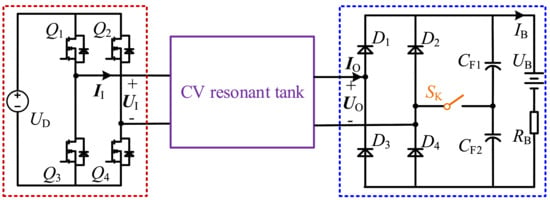
Figure 1.
The schematic diagram of the CV-topology-compensated IPT system utilizing the LLEI technique.
Figure 2 displays the equivalent circuit in heavy-load mode. The LCC-S-resonant tank, which is widely used in the IPT system, is chosen as an application example of the proposed LLEI technique for subsequent analysis. , , and are the corresponding compensation inductor and capacitors on the transmitter. is the series compensation capacitor on the receiver. , , and are the corresponding internal resistances of , , and , respectively. The AC switch is off, and both the HFI on the transmitter and the uncontrollable rectifier on the receiver run in full-bridge mode. The circuit is consistent with the operation of the traditional LCC-S system. It is well known that the CV topology IPT system efficiency is very satisfactory under heavy-load conditions. Therefore, in general, the CV-topology-compensated IPT system is not necessary under a heavy-load condition to take additional measures to further improve the efficiency.

Figure 2.
The equivalent circuit in heavy-load mode.
Figure 3 displays the equivalent circuit in light-load mode. The AC switch is turned on, and the uncontrollable rectifier on the receiver thus serves as a voltage doubler rectifier, which is the so-called half-bridge mode. Additionally, MOSFETs and are always kept off and on, respectively. The HFI on the transmitter is reconfigured as a half-bridge HFI. Therefore, both the rectifier and the inverter run in half-bridge mode at a light-load state.

Figure 3.
The equivalent circuit in light-load mode.
The main motivations for switching between heavy-load and light-load modes can be summarized into two types: The first is to change the working mode of the uncontrolled rectifier to force the ELR to approach the optimal ELR under light-load conditions, so as to greatly increase the light-load efficiency. The second is to change the output–input voltage ratio of the HFI and the uncontrolled rectifier, respectively, to ensure the consistency of the charging voltage in both light-load and heavy-load modes, respectively.
3. Theoretical Analysis
Figure 2 and Figure 3 share the common simplified circuit model, which is displayed in Figure 4. and are the root mean square (RMS) of the input current and voltage of the LCC-S-resonant tank, respectively. and are the RMS of the output current and voltage of the resonant tank, respectively. indicates the RMS of the current flowing through the transmitter-side coil, and M is the mutual inductance between the transceiver-side coils. In addition, represents the ELR of the portion enclosed by the blue dotted line in Figure 1.

Figure 4.
The simplified circuit model.
According to the research in [], when losses caused by the coils are ignored and the system operates in resonance, that is, when Equation (1) is established, the LCC-S topology can achieve load-independent voltage gain, which is expressed as
3.1. Analysis of LLEI Technique
According to [], the final expressions for the power transfer efficiency of LCC-S topology and the corresponding optimal ELR can be, respectively, summarized and derived as
Then, according to the theoretical circuit parameters provided in Table 1, combined with Equations (3) and (4), the efficiency profile of the LCC-S topology against different ELRs are plotted in Figure 5. Clearly, the efficiency in heavy-load mode is high enough, and with the increase in the ELR, the efficiency shows a significant downward trend, especially under light-load conditions. This is mainly due to the gradual deviation of ELR from the optimal ELR.

Table 1.
Theoretical circuit parameters of the LCC-S compensation topology.
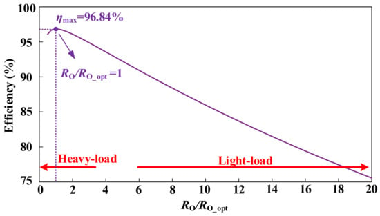
Figure 5.
The efficiency profile of the LCC-S topology against different ELRs.
Therefore, to achieve higher overall efficiency, it should force the ELR of the system as close as possible to the optimal ELR, especially under light-load conditions. The presented LLEI approach can solve this problem pertinently. Based on the analysis in Section 2, the key of this technique is to convert the uncontrollable rectifier from full-bridge to half-bridge mode by activating the AC switch , thereby changing the ELR of the system and then making it approach the optimal ELR to improve efficiency. The specific analysis is as follows:
The ELRs when the uncontrollable rectifier runs in full-bridge and half-bridge modes are described as
From Equation (5), with the same load resistance , the ELR when the uncontrollable rectifier works in half-bridge is one-fourth of that of full-bridge. Thus, as charging progresses, the ELR gradually increases away from the optimal ELR, with this LLEI technique, the ELR can be forced closer to the optimal ELR to improve IPT system efficiency.
3.2. The Consistency of CV Charging in Light-Load and Heavy-Load Modes
The output to input voltage gains of the uncontrollable rectifier operating in full-bridge and half-bridge modes are described in Equation (6).
From Equation (6), the voltage gain of the uncontrollable rectifier in half-bridge mode is twice as much as that in full-bridge mode. This will undoubtedly cause the charging voltage of the system to increase exponentially after enabling the AC switch for the LLEI.
In addition, the output to input voltage gains of the HFI operating in full-bridge and half-bridge modes are described as
From Equation (7), the voltage gain of the HFI in full-bridge mode is twice as much as that in half-bridge mode, which can reasonably neutralize the rise factor of the uncontrollable rectifier operating in half-bridge mode. Therefore, when the system implements LLEI technique, by activating MOSFET and deactivating MOSFET , the HFI is also converted from full-bridge to half-bridge mode, which can effectively solve the above-mentioned problem of voltage multiplication.
Therefore, by choosing the reasonable operating mode in the HFI and uncontrollable rectifier, the system efficiency can be greatly enhanced without affecting CV charging output.
3.3. Implementation of the Presented LLEI Technique
This section introduces the specific implementation method of the presented LLEI technique. The detailed control scheme of the IPT system with the proposed LLEI technique is displayed in Figure 6, where Hall voltage and Hall current sensors are used to measure charging voltage and current to determine the load resistance and assess whether the load is in heavy- or light-load status. Based on this, the corresponding transmitter-side MOSFETs and receiver-side AC switch are driven and controlled accordingly. According to the above theoretical analysis, under the heavy-load condition, both HFI and uncontrollable rectifier operate in full-bridge mode; meanwhile, in the light-load state, both HFI and uncontrollable rectifier work in half-bridge mode. It is worth emphasizing that the reference resistance in the proposed method does not need to be fed back quickly in real time, so weak communication firstly presented in [] with low cost and strong anti-interference can be used, which is a significant difference from the expensive and fast wireless communication links used in the traditional MET methods [,,,,,,,,,,,].
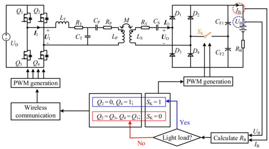
Figure 6.
Control scheme of the IPT system with the presented LLEI technique.
In principle, the reference resistance is determined by the intersection of the efficiency curves of the IPT system operating in half-bridge mode and full-bridge mode. Figure 7 shows efficiency curves in half-bridge and full-bridge modes of the IPT system over the full load range, as well as their respective optimal load resistances and the reference resistance associated with their efficiency crossover point. Based on Equation (5), the optimal load resistances in both half-bridge and full-bridge modes can be derived as
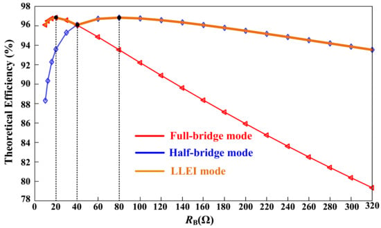
Figure 7.
The theoretical efficiency curves in the different operating modes of the IPT system over the full load range.
Then, the reference resistance which can be determined by solving the geometric mean of the optimal load resistances in both half-bridge mode and full-bridge mode is derived as
As depicted in Figure 7, the red, blue, and orange lines represent the efficiency curves of the half-bridge mode, the full-bridge mode, and the LLEI mode, respectively. By observing the efficiency curve trends in the three modes, the following conclusions can be drawn:
- (1)
- The IPT system in either half-bridge or full-bridge mode has its respective optimal load resistance to improve efficiency. In addition, the optimal load resistance of the full-bridge mode is a quarter of that of the half-bridge, which validates the previous analysis well.
- (2)
- The system efficiency in either half-bridge or full-bridge mode is significantly affected by the time-varying load resistance. However, under heavy-load condition, efficiency in full-bridge mode is relatively higher, while efficiency in half-bridge mode is relatively higher under light-load conditions.
- (3)
- This LLEI technique selects the optimal parts of the efficiency curves in half-bridge and full-bridge modes, thereby improving overall efficiency.
Therefore, the presented LLEI approach can effectively improve the overall system efficiency without affecting the CV output.
4. Experimental Validation
4.1. Experimental Prototype
To validate the practicability of the proposed LLEI method, an experimental prototype is fabricated, as shown in Figure 8.
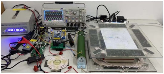
Figure 8.
The experimental prototype of the LCC-S compensated IPT system utilizing the LLEI technique.
The detailed experimental circuit parameters are listed in Table 2 and the specific types of each element adopted in the proposed system are provided in Table 3. The compensation inductor coil and transceiver-side coils are manufactured by Litz wire with low equivalent internal resistance. Ferrites are adopted to enhance magnetic coupling between coils. Table 4 explicitly gives specific information of the relevant parameters in the loosely coupled transformer.

Table 2.
Experimental circuit parameters of the presented system.

Table 3.
Specific types of each element.

Table 4.
Specific information of the relevant parameters in the loosely coupled transformer.
4.2. Experimental Results
Figure 9 displays the experimental efficiency profiles measured over the full load range of the IPT system in half-bridge, full-bridge, and LLEI modes. For the IPT system running in conventional full-bridge mode, with the increase in the load resistance from 16 to 200 , the efficiency gradually declines from the highest point of 91.8% to the lowest point of 77.5%, which is mainly due to the gradual deviation of the load resistance from the optimal point.
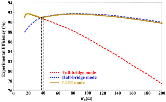
Figure 9.
The experimental efficiency profiles measured over the full load range of the IPT system in full-bridge, half-bridge, and LLEI modes.
For the IPT system running in the half-bridge state, the system efficiency under heavy-load conditions is significantly lower than that in full-bridge mode, while the opposite occurs at the light-load state. Adopting the LLEI technique, the respective optimal efficiency curve segments in the half-bridge and full-bridge modes could be skillfully selected. Efficiency profile in LLEI mode shows that the LLEI technique can ensure a high system efficiency (90.1–91.8%) in the entire load range. Additionally, it is clear that the load point (80 ) associated with the maximum efficiency in the half-bridge mode is four times that (20 ) in the full-bridge mode, which strongly demonstrates that the LLEI technique improves the efficiency in the light-load mode by forcing the ELR of the system as close as possible to the optimal ELR. Moreover, the load points (around 38 ) corresponding to the intersection of the efficiency curves in the light-load and heavy-load modes deviate slightly from the reference resistance point , which is due to measurement errors and extra losses in the actual IPT system. However, the influence of the above deviation on the power transfer efficiency of the IPT system with the LLEI technique is basically negligible.
Figure 10 displays the measured experimental wave forms of inverter output voltage phasor and current phasor , as well as the rectifier input voltage phasor and the current phasor of the presented IPT system at the reference resistance . It is clear that the DC bias in the HFI and the halved voltage amplitude in the rectifier appear in light-load mode, which means the adoption of half-bridge mode in the rectifier and the inverter.
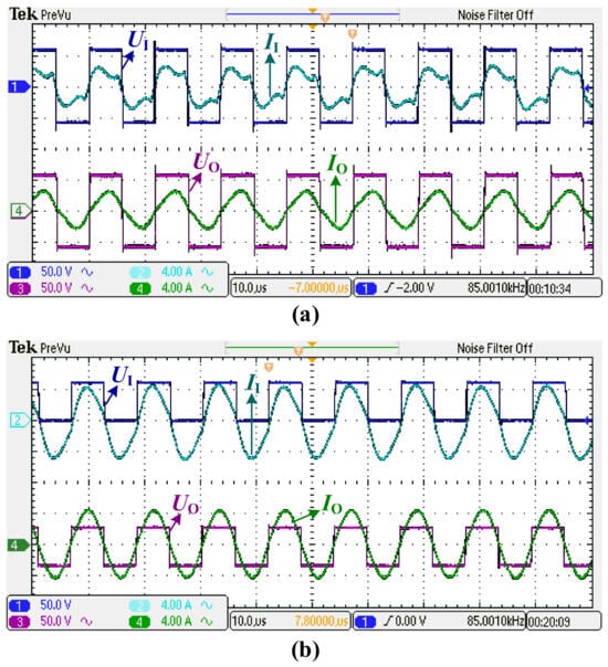
Figure 10.
The measured experimental wave forms of the presented IPT system at the reference resistance point : (a) heavy-load mode; (b) light-load mode.
According to the previous description, under heavy-load conditions, both the inverter and rectifier in the IPT system first operate in traditional full-bridge mode with off. As the load resistance increases, when the IPT system detects the reference resistance point = 40 , is activated, and and are kept on and off, respectively, both rectifier and inverter then run in half-bridge mode under light-load conditions. Figure 11 depicts the transient wave forms of the presented IPT system with a sudden shift from full-bridge to half-bridge mode at the reference resistance point . It can be seen that both the rectifier and inverter operate in full-bridge mode under heavy-load conditions and in the half-bridge mode under a light-load condition. Both the rectifier and the inverter perform their respective operating modes as well as expected. Moreover, the charging voltage of the IPT system is basically remained at a constant value of 60 V before and after the mode switching, which proves that the presented LLEI approach can enhance the system efficiency while still ensuring stability of the system charging output. It is worth emphasizing that the mode switching is implemented only once throughout the entire charging, thus greatly simplifying measurement and control of the system. Moreover, the load resistance changes extremely slowly in practical applications, which reduces the requirement for the wireless communication rate, and more stable and cheaper weak communication modules can be used.
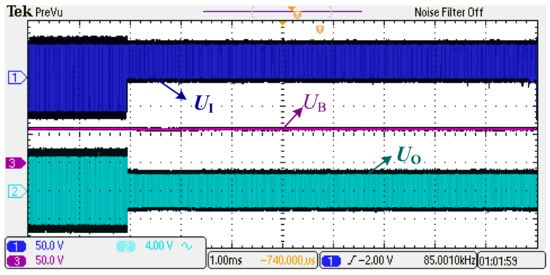
Figure 11.
The transient wave forms of the presented IPT system with a sudden shift from full-bridge to half-bridge mode at the reference resistance point .
To further emphasize the advantages of the proposed LLEI technology, Table 5 presents a comparison between this work and other efficiency improvement schemes. As can be seen, the proposed LLEI technology does not require the introduction of DC-DC converters or transmitter-side current/power sensors, thereby avoiding additional power losses and high costs. In summary, the system design process is simple and efficiency is significantly improved.

Table 5.
Comparison between the present work and prior similar works.
5. Conclusions
This manuscript proposes a light-load efficiency improvement technique for the IPT system. The essence of this technique is to force an ELR under light-load conditions to approximate the optimal ELR for efficiency improvement and maintain the charging voltage roughly constant through a reconfigurable circuit. Under heavy-load conditions, both the rectifier and inverter run in the conventional full-bridge mode with sufficiently satisfactory power transfer efficiency. Under light-load conditions, the rectifier is reconfigured as the voltage doubler rectifier operating in the half-bridge mode for enhancing system efficiency, while the inverter is reconfigured as the half-bridge inverter to keep the charging voltage unchanged. In the experiment, the LLEI technique can lock the system efficiency in the range of 90.1–91.8% throughout the charging process, which is stark contrast to the efficiency range of 77.5–91.8% in the traditional IPT system without adopting the LLEI technique. In addition, compared with the current popular MET methods, the most distinctive superiority of the proposed method is that the extra hardware, fast and expensive wireless communication modules and sophisticated control algorithms are unnecessary, so the IPT system with the LLEI technique is improved and optimized from the perspective of complexity, economy, reliability, and structure.
Author Contributions
Conceptualization, X.Z. and L.Y.; methodology, X.Z.; software, J.W.; validation, X.Z., J.W. and L.Y.; formal analysis, J.W.; investigation, L.Y.; resources, X.Z.; data curation, X.Z.; writing—original draft preparation, X.Z.; writing—review and editing, J.W.; visualization, L.Y.; supervision, J.W.; project administration, X.Z.; funding acquisition, X.Z. All authors have read andagreed to the published version of the manuscript.
Funding
This work was supported in part by Scientific Research Youth Foundation of Hunan Province Education Department of China (22B0803), in part by Employment and Education Foundation of The Second Phase of The Department of College Students of The Ministry of Education of China (20230106677), in part by Guiding Science and Technology Programme Foundation of Yongzhou City of China (2022-YZKJZD-010), in part by Natural Science Foundation of Hunan Province (NO. 2024JJ7186).
Data Availability Statement
Data are contained within the article.
Conflicts of Interest
The authors declare no conflicts of interest.
References
- Zhang, Y.; Wu, Y.; Jiang, S.; Zhou, M.; Zhou, H.; Mao, X.; Jin, T.; Chen, X. An Integrated Electric Vehicle Charging System of Wireless Power Transfer and Auxiliary Power Module with Shared Converter and Magnetic Coupler. IEEE Trans. Ind. Electron. 2024, 71, 10414–10421. [Google Scholar] [CrossRef]
- Yang, L.; Jiang, S.; Zane, R.A.; Carlson, R. A Compact Dual-Channel WPT System with Power Boosting Function Based on Dual-Sided Decoupling Coils. IEEE J. Emerg. Sel. Top. Power Electron. 2023, 11, 2525–2534. [Google Scholar] [CrossRef]
- Bagchi, A.C.; Kamineni, A.; Wang, C.; Cai, C. Review and Comparative Analysis of Topologies and Control Methods in Dynamic Wireless Charging of Electric Vehicles. IEEE J. Emerg. Sel. Top. Power Electron. 2023, 9, 4947–4962. [Google Scholar] [CrossRef]
- Wu, S.; Cai, C.; Zhang, H.; Liu, X.; Chai, W. A Free-Positioning IPT System via Reconfigurable Coil Array Transmitter for Unmanned Aerial Vehicle Applications. IEEE Trans. Transp. Electrif. 2024. online ahead of pub. [Google Scholar]
- Chen, Z.; Zhang, X.; Xu, F.; Li, M.; Yuan, Z.; Yang, Q. Wide Rotation-Misalignment-Tolerance Design of Magnetic Coupled Structure for AUVs Wireless Charging System. IEEE Trans. Ind. Electron. 2024. online ahead of pub. [Google Scholar]
- Gu, Y.; Wang, J.; Liang, Z.; Zhang, Z. Communication-Free Power Control Algorithm for Drone Wireless In-Flight Charging Under Dual-Disturbance of Mutual Inductance and Load. IEEE Trans. Ind. Inform. 2024, 30, 3703–3714. [Google Scholar] [CrossRef]
- Xiao, C.; Cheng, M.; Wei, K. An LCC-C compensated wireless charging system for implantable cardiac pacemakers: Theory, experiment, and safety evaluation. IEEE Trans. Power Electron. 2018, 33, 4894–4905. [Google Scholar] [CrossRef]
- Liu, C.; Jiang, C.; Song, J.; Chau, K.T. An effective sandwiched wireless power transfer system for charging implantable cardiac pacemaker. IEEE Trans. Ind. Electron. 2019, 66, 4108–4117. [Google Scholar] [CrossRef]
- Feng, J.; Li, Q.; Lee, F.C.; Fu, M. Transmitter Coils Design for Free-Positioning Omnidirectional Wireless Power Transfer System. IEEE Trans. Ind. Inform. 2019, 15, 4656–4664. [Google Scholar] [CrossRef]
- Du, S.; Chan, E.K.; Wen, B.; Hong, J.; Widmer, H.; Wheatley, C.E. Wireless Power Transfer Using Oscillating Magnets. IEEE Trans. Ind. Electron. 2018, 65, 6259–6269. [Google Scholar] [CrossRef]
- Yan, Z.; Song, B.; Zhang, Y.; Zhang, K.; Mao, Z.; Hu, Y. A Rotation-Free Wireless Power Transfer System with Stable Output Power and Efficiency for Autonomous Underwater Vehicles. IEEE Trans. Power Electron. 2019, 34, 4005–4008. [Google Scholar] [CrossRef]
- Rong, E.; Sun, P.; Qiao, K.; Zhang, K.; Yang, G.; Wu, Z. Six-Plate and Hybrid-Dielectric Capacitive Coupler for Underwater Wireless Power Transfer. IEEE Trans. Power Electron. 2024, 39, 2867–2881. [Google Scholar] [CrossRef]
- Cai, C.; Wang, J.; Saeedifard, M.; Zhang, P.; Chen, R.; Zhang, J. Gyrator-Gain Variable WPT Topology for MC-Unconstrained CC Output Customization Using Simplified Capacitance Tuning. IEEE Trans. Ind. Electron. 2024, 71, 3594–3605. [Google Scholar] [CrossRef]
- Cai, C.; Wang, J.; Zhao, Y.; Luo, Y.; Yuan, Z.; Mei, X.; Rao, Y.; Yang, L.; Hong, Y.; Wang, C. Hybrid Interference Field Mitigation of Dual-Rectangular Transmitter Pad for Universal Wireless Charging Area Expansion. IEEE Trans. Transp. Electrif. 2023. online ahead of pub. [Google Scholar]
- Li, H.; Li, J.; Wang, K.; Chen, W.; Yang, X. A Maximum Efficiency Point Tracking Control Scheme for Wireless Power Transfer Systems Using Magnetic Resonant Coupling. IEEE Trans. Power Electron. 2015, 30, 3998–4008. [Google Scholar] [CrossRef]
- Zhong, W.X.; Hui, S.Y.R. Maximum Energy Efficiency Tracking for Wireless Power Transfer Systems. IEEE Trans. Power Electron. 2015, 30, 4025–4034. [Google Scholar] [CrossRef]
- Huang, Z.; Wong, S.; Tse, C.K. Control Design for Optimizing Efficiency in Inductive Power Transfer Systems. IEEE Trans. Power Electron. 2018, 33, 4523–4534. [Google Scholar] [CrossRef]
- Yang, Y.; Zhong, W.; Kiratipongvoot, S.; Tan, S.; Hui, S.Y.R. Dynamic Improvement of Series–Series Compensated Wireless Power Transfer Systems Using Discrete Sliding Mode Control. IEEE Trans. Power Electron. 2018, 33, 6351–6360. [Google Scholar] [CrossRef]
- Diekhans, T.; De Doncker, R.W. A Dual-Side Controlled Inductive Power Transfer System Optimized for Large Coupling Factor Variations and Partial Load. IEEE Trans. Power Electron. 2015, 30, 6320–6328. [Google Scholar] [CrossRef]
- Nguyen, B.X.; Vilathgamuwa, D.M.; Foo, G.H.B.; Wang, P.; Ong, A.; Madawala, U.K.; Nguyen, T.D. An Efficiency Optimization Scheme for Bidirectional Inductive Power Transfer Systems. IEEE Trans. Power Electron. 2015, 30, 6310–6319. [Google Scholar] [CrossRef]
- Karakitsios, I.; Palaiogiannis, F.; Markou, A.; Hatziargyriou, N.D. Optimizing the Energy Transfer, with a High System Efficiency in Dynamic Inductive Charging of EVs. IEEE Trans. Veh. Technol. 2018, 67, 4728–4742. [Google Scholar] [CrossRef]
- Li, H.; Fang, J.; Chen, S.; Wang, K.; Tang, Y. Pulse Density Modulation for Maximum Efficiency Point Tracking of Wireless Power Transfer Systems. IEEE Trans. Power Electron. 2018, 33, 5492–5501. [Google Scholar] [CrossRef]
- Li, Z.; Song, K.; Jiang, J.; Zhu, C. Constant Current Charging and Maximum Efficiency Tracking Control Scheme for Supercapacitor Wireless Charging. IEEE Trans. Power Electron. 2018, 33, 9088–9100. [Google Scholar] [CrossRef]
- Yang, L.; Shi, Y.; Wang, M.; Ren, L. Constant Voltage Charging and Maximum Efficiency Tracking for WPT Systems Employing Dual-Side Control Scheme. IEEE J. Emerg. Sel. Top. Power Electron. 2022, 10, 945–955. [Google Scholar] [CrossRef]
- Zhong, W.; Hui, S.Y.R. Maximum Energy Efficiency Operation of Series-Series Resonant Wireless Power Transfer Systems Using On-Off Keying Modulation. IEEE Trans. Power Electron. 2018, 33, 3595–3603. [Google Scholar] [CrossRef]
- Huang, Z.; Wong, S.; Tse, C.K. An Inductive-Power-Transfer Converter with High Efficiency Throughout Battery-Charging Process. IEEE Trans. Power Electron. 2019, 34, 10245–10255. [Google Scholar] [CrossRef]
- Geng, Y.; Li, B.; Yang, Z. A High Efficiency Charging Strategy for a Supercapacitor Using a Wireless Power Transfer System Based on Inductor/Capacitor/Capacitor (LCC) Compensation Topology. Energies 2017, 10, 135. [Google Scholar] [CrossRef]
- Liu, F.; Chen, K.; Zhao, Z.; Li, K.; Yuan, L. Transmitter-Side Control of Both the CC and CV Modes for the Wireless EV Charging System with the Weak Communication. IEEE J. Emerg. Sel. Top. Power Electron. 2018, 6, 955–965. [Google Scholar] [CrossRef]
Disclaimer/Publisher’s Note: The statements, opinions and data contained in all publications are solely those of the individual author(s) and contributor(s) and not of MDPI and/or the editor(s). MDPI and/or the editor(s) disclaim responsibility for any injury to people or property resulting from any ideas, methods, instructions or products referred to in the content. |
© 2024 by the authors. Licensee MDPI, Basel, Switzerland. This article is an open access article distributed under the terms and conditions of the Creative Commons Attribution (CC BY) license (https://creativecommons.org/licenses/by/4.0/).