Abstract
When magnetic saturation occurs during the operation of a permanent magnet (PM) slotless brushless DC motor, the material permeability will no longer be a constant value, and the neglected magnetic saturation model used for motor optimization will no longer be applicable. And considering that the increase in motor torque will lead to a high temperature rise of the winding, therefore, an electromagnetic heat coupling model applicable to the occurrence of magnetic saturation in the motor is established, and the model is utilized in combination with the particle swarm algorithm to enhance the maximum output torque of the motor. Firstly, a 100 W, 16,400 r/min high-speed PM slotless DC brushless motor is taken as the object of study, and its electromagnetic–thermal coupling model is established to derive the analytical equations for the electromagnetic torque with respect to the split ratio, the thickness of the stator yoke, the PM thickness, and the copper loss. Secondly, based on the modeling, the motor was optimized using a particle swarm algorithm to maximize the output torque and minimize the copper loss. Finally, a prototype was fabricated and verified with the prototype through no-load and load experiments. The difference between the theoretical maximum output torque and the experimental maximum output torque is less than 8%. The results show that this method can effectively predict the maximum output torque of the motor in the case of magnetic saturation, and the model is suitable for increasing the maximum output torque of slotless brushless DC motors under space constraints.
1. Introduction
High-speed permanent magnet (PM) slotless brushless DC motors are widely used in applications such as turbines, high-speed pumps, and flywheel energy storage for their high reliability, low maintenance cost, fast response, and high-precision control [1,2,3], and they are also favored in hydroelectric power system applications.
To be able to maximize the performance of the motor under spatial constraints, an accurate electromagnetic model needs to be established, and commonly used modeling methods include the finite element method, the analytical model method, and the magnetic circuit model method [4,5,6]. Understanding the magnetic phenomena occurring in the motor air gap is a prerequisite for accurate calculation of induced voltage, the armature antimagnetic field [7], electromagnetic torque [8,9,10], and eddy current loss calculations [11].
Most analytical models assume the infinite permeability of iron in PM motors and focus only on magnetic field calculations in the vacuum permeability region [12]. Hajdinjak et al. [13] and Si [14], among others, proposed analytical equation models of the air gap, the density distribution in the PM, and a two-dimensional analytical model, respectively, for slotless brushless DC motors. However, these papers ignored the saturation effect, and the motors operated at relatively lower saturation levels. Ignoring the saturation effect will lead to the impact on the motor performance not being fully considered, indicating that there is still room for further optimization of the motor performance. By considering the motor magnetic saturation, it is possible to more accurately predict the magnetic field changes as well as the output torque and efficiency of the motor under actual operating conditions [15].
The effects of magnetic saturation occurring during motor operation are manifold. First, the nonlinear variation in the magnetic field causes the magnetic field density to no longer grow linearly, which affects the output torque and electromagnetic force of the motor. Second, magnetic saturation increases hysteresis loss and iron loss, resulting in lower motor efficiency and shorter service life. In addition, changes in magnetic field distribution and output characteristics affect the reliability and stability of the motor. Therefore, an increasing number of scholars are focusing on this issue and have conducted various studies and provided explanations. Farshadnia et al. [16] considered the non-uniform saturation of the rotor core of the PM synchronous motor, and based on the rotor geometry, an equivalent air-gap function was proposed to simulate the saturation degree of the different regions of the rotor core as well as the relative permeability, but it may have less accuracy when the motor runs at high speeds. Lu et al. [17] proposed a data-driven machine modeling and compensation method to obtain a more accurate model based on the neural network training data, considering that the deep saturation of the motor will be caused by the high-speed operation of the motor; Li et al. [18] proposed an equivalent air-gap function based on the rotor geometry to simulate the saturation and relative permeability of different regions of the rotor core, but there may be the disadvantage of insufficient accuracy when the motor is running at high speeds. They proposed a saturation and terminal effect magnetic circuit model and validated it by finite elements and experiments, but in practical applications, the model parameterization and validation may be difficult because of the need for a large amount of experimental data and complex finite element analysis, as well as the need to take into account the influence of the temperature rise’s effect on the model parameters; Rahideh et al. [19] introduced analytical calculations for a PM slotless brushless DC motor to predict the temperature rise in the air gap for different open-circuit and armature fields in the air gap under different magnetization modes. However, none of them considered the temperature rise variation during motor operation.
The insulated windings of PM slotless brushless DC motors are temperature sensitive, which leads to a sharp increase in copper loss and winding temperature when the motor torque is boosted, and there is a risk of localized overheating of the windings during operation [20]. Therefore, limiting the temperature rise of the stator of the PM is a necessary condition for preventing the insulation from deteriorating and demagnetization of the PM when the motor torque is boosted [21,22]. Asef et al. [23] carried out a PM motor three-dimensional finite element thermal analysis and reduced the temperature rise at the stator core by investigating radial and circumferential airflow ducts; Guo et al. [24] proposed a temperature rise calculation method based on a reduced-order model for variable-condition PM motors in order to accurately carry out the temperature rise calculations and verified that the method can predict the temperature rise at key nodes of PM motors under variable conditions in real time; Li et al. [25] simultaneously considered the temperature rise of the motor as well as the effect of high saturation on the motor. The magnetic properties of the motor under magnetic–thermal coupling were investigated, and it was verified that the magnetic properties of the material at high temperatures would have a certain impact on the performance of the motor, but no optimization of the motor was carried out accordingly; Liu et al. [26] carried out magnetic–thermal coupling after verifying a thermal equivalent circuit model in order to facilitate the reduction of the motor quality while controlling the temperature rise, and provided a reference for the magnetic–thermal coupling of slotless brushless DC motors; Li et al. [27] proposed a shunt ratio optimization method considering winding temperature limitation to improve the torque, but did not explore the effect of other factors of the motor size on the electromagnetic torque; Lekić et al. [28] proposed a new method for analyzing the shunt ratio optimization of a high-torque-density PM brushless DC motor, which considered leakage of the magnetic field and was applicable to large high-pole-count motors with limited copper loss density.
In general, there has not been any torque optimization for slotless brushless DC motors considering temperature rise limitation and magnetic saturation. Magnetic saturation is an important factor that affects motor performance during motor operation, and a low degree of magnetic saturation will lead to a larger optimization space for the motor performance; if the magnetic circuit is oversaturated, the hysteresis loss and iron loss will increase, leading to a reduction in the efficiency of the motor. When just reaching the magnetic saturation state, it will enhance the overall performance of the motor, but then the problem of winding temperature rise will arise; the too-large temperature rise will lead to lower reliability of the motor. To maximize the performance of the PM slotless brushless DC motor and ensure its reliability, it is necessary to limit the temperature rise of each part of the motor while considering the magnetic saturation.
In summary, this paper mainly conducts the following research. First, the analytical electromagnetic model of a permanent magnet slotless brushless DC motor considering the effect of iron core saturation is constructed. By analyzing the saturation characteristics of the iron core material, the equivalent magnetic circuit model of a permanent magnet slotless brushless DC motor considering iron core saturation is constructed, the magnetic field parameters are calculated, and then, based on the electromagnetic law of the motor, the relationship expression between the motor torque, loss, and the design size is deduced, and an analytical electromagnetic model with the size as the input and torque and other performance factors as the output is constructed, and based on the model, the influence of the design size of the motor on the torque law is analyzed. Based on this model, the effect of motor design size on torque is investigated. Second, an optimization method for torque improvement of a permanent magnet slotless brushless DC motor considering temperature limitation is proposed. An analytical electromagnetic–thermal coupling model of the motor is established to reduce the optimization variables through the correlation analysis of electromagnetism and heat in the motor. Taking the temperature limit as the constraint and maximizing the output torque as the objective function, the key dimensions are optimized using a particle swarm algorithm, so that the motor can output the maximum torque within the safe temperature range. The output torque was 0.0566 N·m before optimization, and the output torque after optimization was 0.0700 N·m, which is an improvement of 24% compared with that of the motor. Finally, a prototype was fabricated, and the electromagnetic model and optimization design method were experimentally verified.
2. Magnetic Circuit Model
The PM slotless brushless DC motor optimized in this paper is mainly used as a drive motor for the electric valve actuator to control the sluice gate in a hydroelectric speed control system. Given the limited space, the motor needs to be miniaturized, and the outer diameter and length of the motor stator have been determined. Therefore, the output torque of the motor is limited; to meet the drive requirements of the electric valve, it needs to be matched with a 104:1 reducer, with a maximum transmission efficiency of 59%. For the control of the sluice gate small electric valve, the valve operating torque is required to be 2 N·m, the maximum output torque of the existing motor is 0.056 N·m, and for the reducer drive, there needs to be an output torque of up to 3 N·m, which meets the performance requirements of the electric valve. This further improves the reliability of the system, achieves a greater output torque with the same stator outer diameter, and keeps the temperature rise within an acceptable range. Therefore, the structural dimensions of the high-speed PM slotless brushless DC motor are optimized while considering the temperature rise limit and magnetic saturation. The design parameters of the original high-speed PM slotless brushless DC motor are shown in Table 1.

Table 1.
Design requirements for high-speed PM slotless brushless DC motor.
The layout scheme of the studied high-speed PM slotless brushless DC motor is shown in Figure 1.
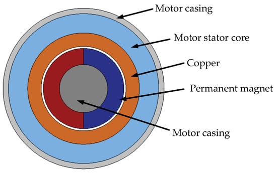
Figure 1.
High-speed PM slotless brushless DC motor layout.
2.1. Modeling the Saturated Magnetic Circuit
As shown in Figure 2, a simplified magnetic circuit model is established for this motor using the equivalent magnetic circuit method, and the magnetic resistance of each part and the air-gap flux density are calculated according to the flux path based on the consideration of the saturated stator–rotor magnetic circuit. In Figure 2, Rg is the PM reluctance, Rg is the air-gap reluctance, Rc is the winding reluctance, Rs is the stator reluctance, Rr is the rotor reluctance, Φg is the air-gap permeability, and FC is the magnetic potential.
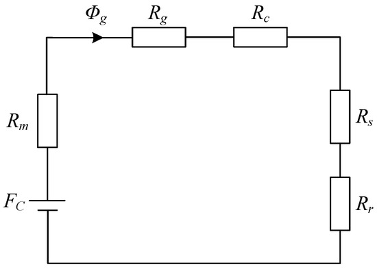
Figure 2.
Magnetic circuit model.
2.2. Derivation of Electromagnetic Torque Relation Equation
The electromagnetic design of a high-speed PM slotless brushless DC motor directly affects the efficiency, output torque, and temperature rise of the motor. The key parameter in the magnetic circuit calculation is the magnetic resistance, and the basic formula for the magnetic resistance is as follows:
where l is the length of the magnetic circuit, m; μ is the permeability of the magnetic circuit material, H/m; A is the cross-sectional area of the magnetic circuit, m2. The derivation of the reluctance of each part of the motor can be carried out according to the above equation, and the stator reluctance, rotor reluctance, winding reluctance, PM reluctance, and air-gap reluctance in the motor can be expressed in the following forms, respectively:
where DO is the stator outer diameter; hj is the stator yoke thickness; μs1 is the permeability of the stator yoke, H/m; μs2 is the permeability of the rotor yoke, H/m; lef is the core length of the motor, m; λ is the split ratio, which is the ratio of the inner diameter of the stator to the outer diameter of the stator and a dimensionless unit; hm is the thickness of the PM, m; Dpm is the outer diameter of the rotor, m; and g is the thickness of the air gap, m. The stator outer diameter of the motor is the core length, m. The rotor’s outer diameter of the motor is the stator’s outer diameter.
If magnetic saturation occurs during the operation of a motor, the permeability will no longer be a constant but will be a function of nonlinear variation. In this case, an iterative method is required to determine the magnetic permeability of the stator. The iterative process is shown in Figure 3.
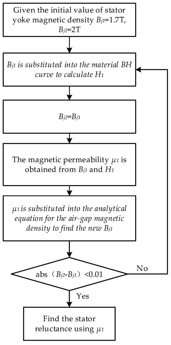
Figure 3.
Consider the iterative process of the saturated calculation of magnetic permeability.
On this basis, the air-gap flux can be expressed as
The air-gap flux density can be expressed as
According to the internal geometrical relations of the motor and the expression for the air-gap flux density, it is possible to express the stator yoke magnetic flux density as an expression related to the air-gap flux density in the form shown as
Since the stator yoke magnetic flux density has an important influence on the consideration of core loss, it can relate the air-gap flux density to the core loss through Equation (9), which facilitates further exploration of the relationship between the air-gap flux density and the loss in each part.
An expression for the average electromagnetic torque of a motor with a star-connected rhombic winding can be obtained based on the mechanical work done by the rotor in rotational motion during one cycle as [29]
where Iacp is the average armature current, A; Bg is the air-gap flux density, T; r is the radius of the armature winding, m; lef is the axial length of the core, m; W is the total number of turns of the armature winding.
The motor copper loss expression is shown as
where Ra is the armature resistance, Ω; the average armature current and armature resistance can be calculated according to Equations (12) and (13), respectively, shown as
where U is the voltage applied to the three-phase armature winding terminals, V; Bg is the air-gap flux density, T; d denotes the average armature radius, m; lef is the axial length of the air gap, m; Bg0 = 0.62 T, which denotes the no-load air-gap flux density; n0 is the ideal no-load rotational speed of the motor, r/s; ρCu is the electrical resistivity of copper, and ρCu is ρCu at 20 °C and ρCu = 1.75 × 10⁻⁸ Ω·m; d is the outer diameter of the wire without insulation, m; W is the total number of turns of the armature winding; d and W can be calculated according to Equations (14) and (15):
Combined with the above equation, the electromagnetic torque can be written as an analytical equation for the copper loss, PM thickness, stator yoke thickness, and winding thickness, expressed as
2.3. Loss and Output Torque Calculation
In the process of high-speed operation of the motor, there will be other losses, mainly including stator core loss, wind friction loss, and bearing loss.
2.3.1. Stator Core Loss
Stator iron core loss refers to the energy loss caused by the alternating electromagnetic field in the motor iron core. Motor iron loss accounts for a large proportion of the total motor loss and is one of the main losses of the motor [30]. It can be determined by the following equation as
where Pj is the iron loss per unit mass, W/kg; f is the frequency, Hz; Gj is the mass of the stator yoke, kg; Kh and Ke are the coefficients for calculating the hysteresis loss and eddy current loss in the iron loss, respectively, in which Ke = 5.79366 × 10⁻⁵ and Kh = 1.01515 × 10⁻². α and β are temperature coefficients used for calculating the iron loss formula, which is a dimensionless unit, and in which α = 1.31. Bm is the peak value of the stator core magnetic density, i.e., the maximum value of the stator core magnetic density after considering saturation. The mass density of the stator yoke section, ρ310-50 = 7650 kg/m3; hj is the thickness of the stator yoke, m. The value of s is frequency dependent.
2.3.2. Air Friction Loss
Wind friction loss is the loss of energy due to friction between rotating mechanical parts and air molecules. The expression for the total wind friction loss is
where ΔPa is the air-gap friction loss due to resistance torque, W; ΔPad is the friction loss on the flat circular surface of the rotor due to resistance torque, W; ΔPc is the loss due to axial cooling medium flow, W. ΔPa can be calculated by the following equation:
where cf is the coefficient of friction, ρk is the density of air at Θ = 100 °C, kg/m3; ρdn is the dynamic viscosity of air at Θ = 100 °C, kg/m3; Ω is the angular velocity of the rotor, rad/s; D2out is the outer diameter of the rotor, m; Re is the Reynolds number; ΔPad is calculated as follows:
where dsh denotes the diameter of the shaft, m; cfd denotes the friction coefficient of the rotating disk. The loss due to axial cooling medium flow is shown as
where vax is the axial velocity through the air gap, the value of which has a magnitude of 10 m/s; the average tangential velocity of the cooling air in the air gap is vt, m/s.
2.3.3. Bearing Loss
Bearing loss usually refers to the energy loss caused by the friction of the bearing; bearing design and maintenance are directly related to the size of the energy loss and the service life of the equipment. The formula for calculating bearing loss is
where, assuming kfb = 2, this parameter is mainly used to simplify the calculation or to adapt to a specific design criterion; D2out is the outer diameter of the rotor, m; dsh is the diameter of the rotor shaft, m; mr is the mass of the rotor, kg; according to the obtained equation, it can be observed that the bearing loss is directly proportional to the mass of the motor rotor.
2.3.4. Calculation of Motor Output Torque
The output torque of the motor can finally be expressed as the following equation:
where T2 is the output torque of the motor, N·m; Temcp is the average electromagnetic torque of the motor, N·m; PFe is the iron loss of the motor in W; ΔPwind is the total wind friction loss of the motor, W; Pfr is the bearing loss of the motor, W; and wr is the mechanical angular velocity, rad/s. Thus, the output torque of the motor is finally expressed as an analytical equation related to the stator cleavage ratio, PM thickness, stator yoke thickness, winding thickness, and copper loss into an analytical equation related to the split ratio, PM thickness, stator yoke thickness, winding thickness, and copper loss.
3. Influence of Motor Structure Parameters on Output Torque
After analyzing the derivation process of the previous analytical equation, it can be seen that all the variables related to the calculation of motor torque can be expressed in terms of the internal structure parameters of the motor as well as the material properties. In the case of a certain outer diameter, the dimensional space inside the motor is limited, so several influential parameters affecting the motor torque are analyzed. The following section mainly discusses the effects of the saturation of the PM thickness hm, the stator yoke thickness hj, the winding thickness hc, the split ratio λ, and the shaft diameter dsh on the output torque.
Since the existence of an air gap will lead to an increase in magnetic resistance and affect the efficiency of the motor, the smaller the thickness of the air gap is, the better it is, and when taking the air gap as an optimization variable, it is easy to make the final optimization result fall into the local optimum solution; the thickness of the air gap is selected to have a fixed value of 0.4 mm.
For the convenience of the study, the winding thickness hc is defined here as a variable related to the stator yoke thickness hj, i.e., hc = chj, and the named coefficient c is the winding thickness ratio. The shaft diameter dsh is defined as a variable related to the stator inner diameter Di, i.e., dsh = kDi, and the named coefficient k is the shaft diameter constant. Define the PM thickness hm as a variable related to the stator inner diameter Di, i.e., hm = jDi, naming j as the magnetic diameter ratio.
Fixing the stator outer diameter dimensions, the discussion of the rotor section can be divided into two cases:
In the case of a constant split ratio, i.e., the inner diameter of the stator winding of the motor is constant, the effect of winding thickness ratio c on the torque is shown in Figure 4.
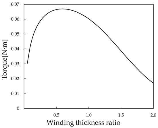
Figure 4.
Winding thickness ratio and torque relationship curve.
From Figure 4, it can be seen that the output torque achieves a maximum value of 0.067 N·m when c = 0.6, indicating that when the split ratio is certain, there exists a winding thickness ratio that can maximize the output torque.
When the split ratio changes and the stator outer diameter is certain, the inner diameter of the stator winding changes, and the change in the inner diameter will inevitably affect the change in the size of the rotor part. In that case, due to the mutual constraints of the shaft diameter and the PM thickness, it can be divided into the following three cases for discussion.
(1) The stator cleavage ratio changes, the PM thickness remains unchanged, and the shaft diameter changes. At this time, the relationship between the shaft diameter and the inner diameter of the stator winding is defined as dsh = kDi. It is possible to obtain the winding thickness ratio and torque relationship curves under different values of k as shown in Figure 5.
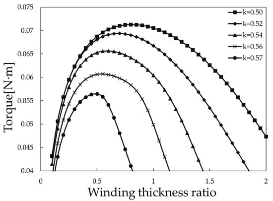
Figure 5.
Relationship curve between winding thickness ratio and torque under different k values.
When the shaft diameter ratio k is certain, there always exists a point of optimal winding thickness ratio that maximizes the output torque. Under the prototype size constraints, as the shaft diameter ratio decreases, the maximum output torque of the motor will be achieved at a larger winding thickness ratio. When the winding thickness ratio is certain, the output torque increases as the shaft diameter ratio decreases.
(2) The stator cleavage ratio changes, the shaft diameter remains the same, and the PM thickness changes. At this time, the relation equation between the PM thickness and the inner diameter of the stator winding is defined as hm = jDi.
From Figure 6, the following conclusions can be drawn: when the magnetic split ratio j is certain, there always exists a point of optimal winding thickness ratio, which makes the output torque maximized; under the limiting conditions of the prototype size, the output torque of the motor increases with the increase of the magnetic split ratio; when the winding thickness ratio is certain, the maximum output torque of the motor increases with the increase in the magnetic split ratio.
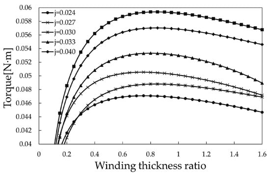
Figure 6.
Relationship curve between winding thickness ratio and torque under different j values.
(3) The stator cleavage ratio changes, the shaft diameter and the PM thickness change at the same time, and at this time, the relationship between the shaft diameter and the thickness of the PM is expressed as dsh = ehm. After the analysis of the first two cases, the third case will not be discussed separately; it will be further demonstrated in the following by using the particle swarm algorithm to carry out the sensitivity analysis.
From the above conclusion, it is easy to see that changes in the winding thickness ratio, magnetic diameter ratio, and shaft diameter ratio all affect the output torque change situation. Under the same size limitations, the effective degree of optimization of the shaft diameter ratio on the maximum output torque is better than the effective degree of optimization of the magnetic diameter ratio on the maximum output torque.
In motor design, the realization of maximum output torque involves the comprehensive consideration of several factors. When the split ratio changes while the shaft diameter remains constant and the thickness of the PM changes, the maximum output torque is limited for various reasons. First, the motor size limits the increase in PM thickness. Second, once the shaft diameter is determined, the room for increasing the PM thickness is further limited. The PM thickness is critical to the motor’s output torque because it directly affects the motor’s flux density. A larger flux density produces a larger electromagnetic torque. Some scholars have simplified the motor structure by using a cylindrical PM directly as the motor shaft to achieve a larger output torque. However, in practical applications, issues such as shaft stiffness and manufacturing cost need to be considered. Therefore, instead of further discussion on the change in split ratio and the simultaneous change in shaft diameter and PM thickness, the optimal combination of motor structure parameters is obtained here based on the analytical model using the particle swarm algorithm to achieve the goal of maximum output torque.
4. Motor Output Torque Optimization
4.1. Modeling of the Lumped-Parameter Thermal Circuit
To further discuss the effect of temperature rises on the output torque of the motor, the lumped-parameter thermal circuit model is developed for this motor, as shown in Figure 7.
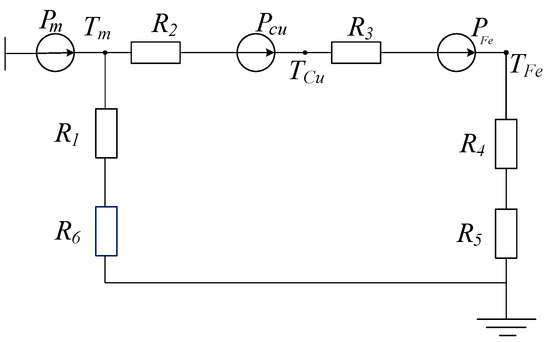
Figure 7.
Lumped parameter thermal path model.
In the figure, Pm denotes the eddy current loss of the PM; PCu denotes the copper loss of the winding; PFe denotes the iron loss generated by the motor; R1 denotes the thermal resistance between the rotating shaft of the PM; R2 denotes the thermal resistance between the surface of the PM and the winding; R3 denotes the thermal resistance between the winding and the inner surface of the stator iron core; R4 denotes the thermal resistance between the outer surface of the stator iron core and the inner surface of the chassis; R5 denotes the thermal resistance between the outer surface of the chassis and the air; R6 denotes the thermal resistance between the motor rotor shaft and the air contact surface; Tm denotes the average internal temperature of the PM; TCu denotes the average internal temperature of the motor winding; and TFe denotes the average temperature of the motor stator core.
This thermal circuit model has the following relational equation:
where ΔτFe is the temperature rise of the stator core, °C; ΔτCu is the temperature rise of the stator windings, °C; Δτm1 is the temperature rise generated by the heat exchange between the PM and the stator part of the motor, °C.
Based on the above derivation, the expression for copper loss can be obtained as
In the described equation, we can clearly distinguish three main temperature rise components: the temperature rise ΔτFe of the stator core, the temperature rise ΔτCu of the stator windings, and the temperature rise Δτm1 resulting from the heat exchange between the PM and the stator part of the motor. However, in the slotless brushless DC motors discussed in this paper, the iron dissipation is relatively small, and, therefore, the temperature rise ΔτFe of the stator core and the heat exchange Δτm1 associated with it can be reasonably neglected. Our discussion will focus on the temperature rise ΔτCu of the stator windings, as this is the most significant thermal effect in the present case’s associated heat exchange Δτm1. Our discussion will focus on the temperature rise ΔτCu of the stator windings since this is the most significant thermal effect in the present case. This decision is based on an in-depth analysis of the working principle and actual operation of the motor and ensures that we can concentrate on the most critical factors in depth, making our discussion more focused.
Combining Equations (37) and (38), we can obtain the analytical equation of the output torque of the motor after considering the saturation of the magnetic circuit under the temperature rise limitation, which is expressed as the equations of the split ratio λ, the thickness of the PM hm, and the thickness of the stator yoke hj, and we can solve the differential equations of dT2/dλ = 0, dT2/dhm = 0, and dT2/dhj = 0 for each of the parameters to obtain the maximum torque under the individual consideration of each factor. However, the above expressions are too complicated to use to solve the differential equations, and only a local optimal solution will be obtained, which is often not able to achieve the global maximization of torque. The particle swarm algorithm is a heuristic optimization algorithm, which performs well in continuous optimization problems, does not easily fall into the local optimum, and is not sensitive to the initial value, so it can adaptively find the maximum value of output torque that is globally optimal.
4.2. Optimization of Motor Output Torque by Particle Swarm Algorithm
Based on the model established in the previous section, the dimensions of each part of the motor are parameterized. For the convenience of the study, the changes in c, k, and j can be expressed in terms of changes in the internal dimensions of the motor. The maximum output torque and minimum loss are taken as the objectives, and the effects of magnetic saturation and temperature rise conditions on the motor are considered comprehensively, and then the motor is optimized using the particle swarm algorithm. The best motor optimization solution is not obtained when the output torque is maximum, because it is necessary to balance the conflicts between different objectives to find the best design solution. The Table 2 shows the initial motor design optimization parameter interval for the particle swarm optimization process.

Table 2.
Optimized parameter range for electric motor design.
The results of each optimization of the particle swarm algorithm are plotted in the form of a scatter plot, and the optimization process chart can be obtained by taking the number of generations of the design scheme as the horizontal coordinate, as shown in Figure 8, and the magnitude of the output torque of the motor and the total loss of the motor as the vertical coordinate.
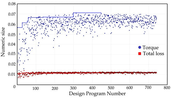
Figure 8.
Target history graph.
In the given range of the respective variables, after a certain number of iterations, the maximum output torque of the motor and the total loss of the motor gradually stabilized; the optimization process was the change in the two response quantities, set as a “performance” parameter, to measure the advantages and disadvantages of each scheme. Finally, we found the maximum motor output torque, the total loss of the program, and the motor design program, shown in Table 3.

Table 3.
Best working point design scheme for motor performance.
Compared to the initial value, the maximum torque was increased by 24% using this algorithm under the same size constraints, which is in line with the initial conceptualization of the maximum torque increase for the motor. Due to the contradictory nature of the two design objectives of the motor, the optimal solution is, thus, neither the one at the minimum motor loss nor the one at the maximum motor output torque in the figure.
Through a sensitivity analysis of the stator inner diameter, stator winding thickness, and PM thickness on this basis, we were able to obtain the correlation coefficients shown in Figure 9.
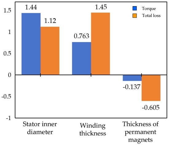
Figure 9.
Sensitivity analysis of the influence of parameters on motor torque.
Since the outer diameter of the motor stator remained unchanged during the optimization process, the change in the inner diameter of the stator characterizes the change in the split ratio, and the change in the winding thickness characterizes the change in the winding ratio. The sensitivity threshold for each parameter was −0.67 for the torque and −0.64 for the total motor loss; from the sensitivity analysis, it can be seen that the split ratio and winding thickness ratio have significant effects on the torque and the total motor loss, whereas the PM thickness does not have a significant effect on the torque and the motor loss. Therefore, in the design of a PM slotless brushless DC motor, we generally determine the PM thickness according to the cost of the motor, and the optimization of the motor is mainly aimed at the optimization of the split ratio and winding thickness ratio.
The analytical optimization method was validated by finite element simulation. The finite element simulation was compared with the analytically calculated values. The results are shown in Figure 10. When the permanent magnet thickness and winding thickness were fixed, the stator split ratios λ = 0.48, 0.50, 0.52, 0.54, 0.56 were selected for the finite element simulation in the finite element model, and the results of the finite element simulation and analytically calculated values of the motor torque with the changes in the stator split ratio were obtained, as shown in Figure 10a. The simulation results of the FE discharge of the motor torque agree with the trend of the analytical results. The simulation value of the optimum split ratio is the same as the analytic value; both are 0.52. The maximum error of torque is 3%.
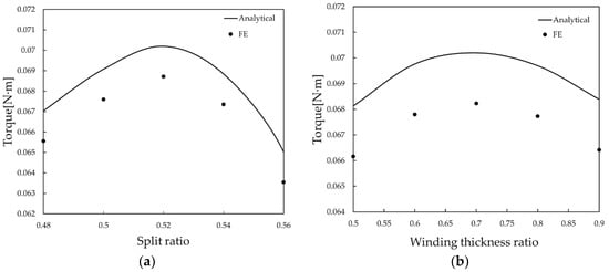
Figure 10.
(a) FE predicted variation in output torque with split ratio; (b) FE prediction of output torque with winding thickness ratio.
When the permanent magnet thickness and stator split ratio were constant, the winding thickness ratios c = 0.5, 0.6, 0.7, 0.8, 0.9 were selected for finite element simulation, and the results of finite element simulation and analytical value comparison of the motor torque with the change in winding thickness ratio are shown in Figure 10b. The simulation results of the FE discharge of the motor torque agree with the trend of the analytical results. The simulation results of the FE discharge of the motor torque agree with the trend of the analytical results. The simulation value of the optimum split ratio is the same as the analytic value; both are 0.52. The value of the optimum winding thickness ratio is the same as the analyzed value, which is 0.7. The maximum error of torque is 2.2%.
When optimizing motor torque, focusing solely on the permanent magnet thickness might yield high torque, but it is neither cost-effective nor practical. While the key variables include the stator split ratio, permanent magnet thickness, and winding thickness, the permanent magnet thickness should be considered only as an auxiliary variable. The stator split ratio and winding thickness are the primary factors that significantly influence performance. Therefore, the validation process should primarily examine scenarios where the stator split ratio and winding thickness are used as single variables.
The output torque of the optimized motor is shown in Figure 11. Compared with the pre-optimization motor, the output torque was increased from 0.0610 N·m to 0.0695 N·m, which indicates that the optimized motor scheme can provide more torque for the electric valve actuator under the same condition constraints.
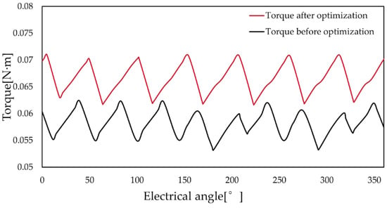
Figure 11.
Comparison of motor torque curves before and after optimization.
The operating range of the optimized motor, shown in Figure 12, which is the speed–torque curve of this PM synchronous motor, visually demonstrates the maximum torque that the motor can achieve at different speeds. The motor is still able to output a large torque at 19,000 r/min, but as the speed continues to increase, the output torque gradually decreases.
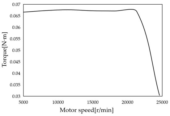
Figure 12.
The operating range curve of the optimized motor.
As shown in Figure 13, considering the air-gap flux density curve of the optimized motor, compared with the pre-optimization condition, the no-load air-gap magnetism was increased from 0.611 T to 0.624 T, which indicates that the magnetic field distribution of the optimized motor is more centralized and uniform in the no-load condition. The increase in the no-load air-gap permeability means that a stronger magnetic field is generated in the air gap of the motor.
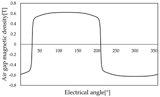
Figure 13.
No-load air-gap flux density.
According to the actual working conditions of the electric valve operation, to determine the running time of the high-speed PM slotless brushless DC motor, a command is issued to the implementation of the completion of up to 3 min, the flow signal is collected once in 3~5 min. Based on this, we set the maximum time of continuous operation of the motor to 180 min, and its temperature simulation after 180 min of maximum power work, including the temperature rise of the motor parts, is shown in Figure 14.
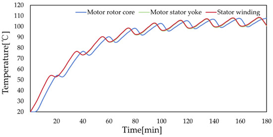
Figure 14.
Temperature rise of various parts of the motor after optimization.
The temperature results are shown in Figure 15; it reached 108 °C, which both satisfies the limits of the coil insulation as well as the operating temperature of the PM.
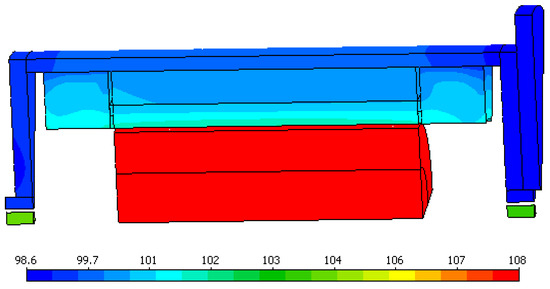
Figure 15.
Temperature simulation.
5. Experimental Verification of the Prototype
In this paper, according to the optimized size structure of the motor, the prototype was made and load experiments and no-load experiments were carried out to test the maximum output torque of the prototype, in order to verify the rationality of the motor optimization results. In the no-load experiment, the three-phase symmetrical resistance was used to simulate the load size when it is used for electric valve actuators, to determine whether the maximum output torque of the motor meets the design requirements, and to compare the experimental results with the calculated values to analyze the results.
5.1. Prototype
According to the final size results of torque optimization, a prototype of a high-speed PM slotless brushless DC motor was fabricated, and a diamond-shaped winding was used in the winding part, which has no stator slots inside the motor to reduce the iron and copper loss and thus improve the efficiency of the motor; the slotless design can arrange the windings more compactly inside the stator, thus improving the power density of the motor. In addition, it can also reduce noise as well as simplify the manufacturing process, which reduces the production cost: the winding and the stator yoke as shown in Figure 16.
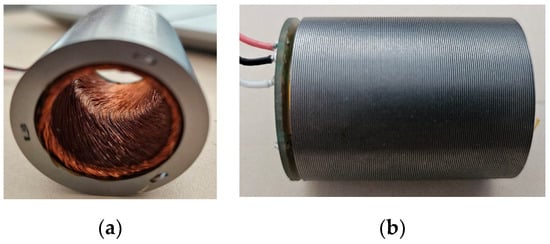
Figure 16.
(a) Stator winding; (b) stator yoke.
The average diameter of the winding cylinder is 19.65 mm, the pole pitch is 30.87 mm, the side length of the rhombic winding is 20.84 mm, the cross-sectional area of the hollow cup winding is 132.1 mm2, the total number of turns of the hollow cup winding is 216 turns, the number of winding turns of each phase is 73 turns, the filling coefficient is 60%, the wire diameter is 0.67 mm, the maximum outer diameter of the enameled wire is 0.73 mm, and the insulation level is C grade (220 °C class). The unfolding diagram of the winding is shown in Figure 17. Figure 17 shows the diamond winding structure of a permanent magnet slotless brushless DC motor. A, B, and C are the windings for phases A, B, and C, respectively, and N is the neutral point where the three phases connect in a star connection.
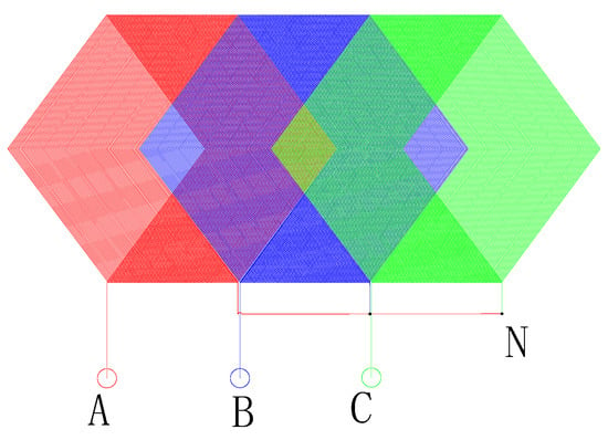
Figure 17.
Stator part of high-speed PM slotless brushless DC motor winding layout.
Winding layout of a high-speed permanent magnet slotless brushless DC motor.
The overall structure of the final high-speed PM slotless brushless DC motor prototype is shown in Figure 18.
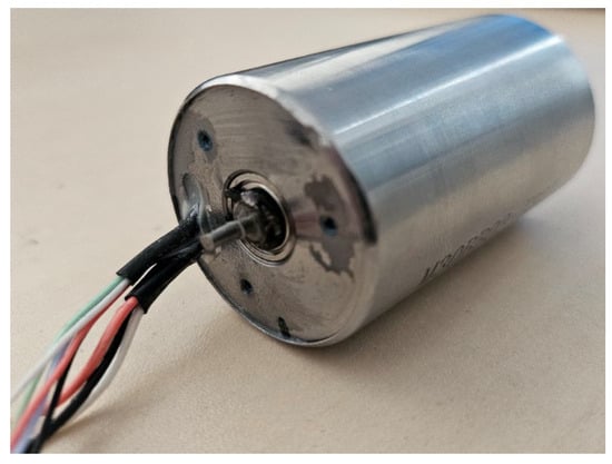
Figure 18.
Prototype.
5.2. Experimental Design
Two prototypes were used for the construction of the motor-to-drag experimental platform; the motor under test was used as a motor, another identical motor was used as a generator, a three-phase symmetrical load was used as the generator’s load; the generator load could be adjusted to change the motor’s load torque; the test bench is shown in Figure 18.
The equipment for the experiment mainly consists of the power analyzer, DC power supply, oscilloscope, LCR meter, tachometer, and three-phase sliding resistor. The experimental bench is shown in Figure 19.
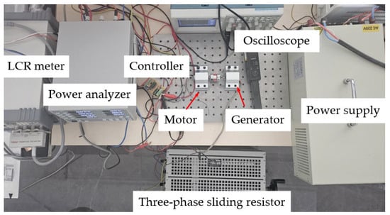
Figure 19.
Motor set-up experiment.
5.3. Motor Resistance Test
The resistance of the prototype was tested with an LCR meter, respectively, the AB, BC, and CA phase resistances of the two prototypes were tested, the motor was connected by a star, and the measured data were organized to be able to obtain the experimental data shown in Table 4.

Table 4.
Motor resistance test.
Based on the resistance calculation of the star connection, the average phase resistance of prototype 1 was calculated to be 0.827 Ω and the average phase resistance of prototype 2 was calculated to be 0.836 Ω.
5.4. No-Load Experiment
The no-load performance of the motor was tested on the prototype, and the speed of the control motor was 16,400 r/min, as shown in Figure 20.
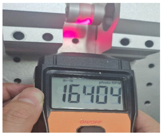
Figure 20.
No-load experimental speed.
No-load experiments were performed on the prototype, and the results are shown in Figure 21.

Figure 21.
No-load experimental measurement data.
Since the load was not connected at that time, the calculated power was the copper loss of the motor, as well as the sum of mechanical loss and other loss of the two motors. The formula is as follows:
where P is the no-load input power, read by the power analyzer; according to the data measured in three experiments, the average value was 33.87 W; I is the phase current, read by the three-phase power meter; according to the data measured in three experiments, the average value was 0.93 A; R is the phase resistance; the average phase resistance measured by the previous section was 0.8266 Ω; Pt is the sum of iron loss and other loss of the prototype.
This could be calculated for each prototype, in addition to copper loss and other losses, including iron loss, and the sum was 15.86 W.
5.5. Load Experiment
According to 150% of the maximum torque required to open and close the electric actuator, the maximum rated torque was measured to simulate the torque required by the electric valve actuator, so that the motor operated at a working condition of 16,400 r/min. The output power measurement is shown in Figure 22.

Figure 22.
Power measurement.
The data and calculations for the three experiments can be known from the three-phase power meter in the following Table 5. The output torque can be calculated as
where PO is the output power, W.

Table 5.
Experimental data processing.
5.6. Experimental Results and Error Analysis
The experimental results as well as the calculated results are shown in Table 6.

Table 6.
Analysis of experimental results.
Error analysis:
- (1)
- The calculated value did not consider the effect of magnetic leakage on the magnetic circuit, and this part of the loss was ignored, resulting in a high calculated value.
- (2)
- There may be quality differences between different batches or models of experimental equipment, such as the degree of wear and tear, manufacturing process, etc., and these differences will also have an impact on the results of the experiment.
- (3)
- There may be slight differences in the conditions of each experiment, such as temperature, humidity, and other environmental factors, and these differences may affect the accuracy of the experimental results.
6. Conclusions
For PM slotless brushless DC motors, whether the magnetic circuit is saturated or not affects the performance of the motor under the size limitation condition. The motor magnetic circuit torque enhancement leads to local overheating of the windings, and an optimization method for slotless brushless DC motors considering magnetic saturation under the motor temperature-rise-limiting conditions is proposed. A magneto-thermal coupling model between the motor output torque and temperature and size was derived, based on which the motor output torque was maximized by optimizing the internal structure parameters of the motor using a particle swarm algorithm.
The optimization results show that the split ratio and winding thickness ratio have a significant effect on the maximum torque of the motor when performing the optimization of the PM slotless brushless DC motor. The selection of PM thickness is generally based on the stiffness of the motor as well as the cost of the motor, because a thicker PM means that a larger magnetic flux is provided into the magnetic circuit, and with an increase in the thickness of the PM, the output torque will always show an upward trend, but it would make the cost of the motor too high, and its low-cost advantage would be lost. The analytical calculation results are compared with the finite element simulation results, and the maximum error is not more than 3%. The analytical prediction results are in good agreement with the experimental results and the error is not more than 8%, which shows that the method can optimize the maximum torque of the PM slotless brushless DC motor effectively.
To improve the maximum motor output torque of the PM brushless DC motor under the limitation of limited space size, an analytical electromagnetic model of a high-speed permanent magnet slotless brushless DC motor considering the effect of iron core saturation was constructed and an optimization method of a permanent magnet slotless brushless DC motor torque enhancement considering the temperature limitation is proposed. The motor output torque is improved while the electric valve can operate efficiently, reliably, and smoothly.
This method provides an effective way to solve the problem of increasing torque when certain slotless PM brushless DC motors in industry, agriculture, aerospace, and other fields are limited by size and temperature rise constraints, and has a promising application.
Author Contributions
Conceptualization, W.Z.; Investigation, P.L.; Writing—original draft, Z.X.; Writing—review & editing, Q.L. All authors have read and agreed to the published version of the manuscript.
Funding
This research received no external funding.
Data Availability Statement
The original contributions presented in the study are included in the article, further inquiries can be directed to the corresponding author.
Conflicts of Interest
The authors declare no conflict of interest.
References
- He, T.; Zhu, Z.-Q.; Xu, F.; Bin, H.; Wu, D.; Gong, L.; Chen, J. Comparative study of 6-slot/2-pole high-speed permanent magnet motors with different winding configurations. IEEE Trans. Ind. Appl. 2021, 57, 5864–5875. [Google Scholar] [CrossRef]
- Liu, G.; Liu, M.; Zhang, Y.; Wang, H.; Gerada, C. High-speed permanent magnet synchronous motor iron loss calculation method considering multiphysics factors. IEEE Trans. Ind. Electron. 2019, 67, 5360–5368. [Google Scholar] [CrossRef]
- Islam, M.S.; Mikail, R.; Husain, I. Slotless lightweight motor for aerial applications. IEEE Trans. Ind. Appl. 2019, 55, 5789–5799. [Google Scholar] [CrossRef]
- Zhao, W. Research on Simulation of Electromagnetic Field of DC Motor Based on Finite Element Analysis. J. Phys. Conf. Ser. 2020, 1549, 052102. [Google Scholar] [CrossRef]
- Ma, C.; Chen, C.; Li, Q.; Gao, H.; Kang, Q.; Fang, J.; Cui, H.; Teng, K.; Lv, X. Analytical calculation of no-load magnetic field of external rotor permanent magnet brushless direct current motor used as in-wheel motor of electric vehicle. IEEE Trans. Magn. 2018, 54, 8103106. [Google Scholar] [CrossRef]
- Lv, G.; Cui, L. Analysis and Calculation for a Novel Transverse Flux Linear Synchronous Motor With 3-D Magnetic Circuit Method. IEEE Trans. Ind. Electron. 2024, in press. [Google Scholar] [CrossRef]
- Zhu, Z.; Howe, D. Instantaneous magnetic field distribution in brushless permanent magnet DC motors. II. Armature-reaction field. IEEE Trans. Magn. 1993, 29, 136–142. [Google Scholar] [CrossRef]
- Lee, S.; Kim, C.; Choo, Y.; Yun, G.; Lee, C. Torque analysis of a permanent magnet synchronous motor using flux densities in air gap. AIP Adv. 2023, 13, 025313. [Google Scholar] [CrossRef]
- Wang, P.; Hua, W.; Zhang, G.; Wang, B.; Cheng, M. Principle of flux-switching PM machine by magnetic field modulation theory part II: Electromagnetic torque generation. IEEE Trans. Ind. Electron. 2021, 69, 2437–2446. [Google Scholar] [CrossRef]
- Lannoo, J.; Vanoost, D.; Peuteman, J.; Debruyne, S.; De Gersem, H.; Pissoort, D. Improved air gap permeance model to characterise the transient behaviour of electrical machines using magnetic equivalent circuit method. Int. J. Numer. Model. Electron. Netw. Devices Fields 2020, 33, e2749. [Google Scholar] [CrossRef]
- Ayana, T.; Morawiec, M.; Wogi, L. Multiscalar Control Based Airgap Flux Optimization of Induction Motor for Loss Minimization. IEEE Access 2024, 12, 19993–20002. [Google Scholar] [CrossRef]
- Markovic, M.; Perriard, Y. Analytical solution for rotor eddy-current losses in a slotless permanent-magnet motor: The case of current sheet excitation. IEEE Trans. Magn. 2008, 44, 386–393. [Google Scholar] [CrossRef]
- Hajdinjak, M.; Miljavec, D. Analytical calculation of the magnetic field distribution in slotless brushless machines with U-shaped interior permanent magnets. IEEE Trans. Ind. Electron. 2019, 67, 6721–6731. [Google Scholar] [CrossRef]
- Si, J.; Wei, Y.; Nie, R.; Liang, J.; Gan, C.; Hu, Y. Analytical modeling of slotless axial flux permanent magnet motor with equidirectional toroidal winding. IEEE Trans. Ind. Electron. 2022, 70, 10420–10430. [Google Scholar] [CrossRef]
- Lee, M.; Koo, B.; Nam, K. Analytic optimization of the Halbach array slotless motor considering stator yoke saturation. IEEE Trans. Magn. 2020, 57, 8200806. [Google Scholar] [CrossRef]
- Farshadnia, M.; Cheema, M.A.M.; Dutta, R.; Fletcher, J.E. Analytical modeling of armature reaction air-gap flux density considering the non-homogeneously saturated rotor in a fractional-slot concentrated-wound IPM machine. IEEE Trans. Magn. 2016, 53, 8200412. [Google Scholar] [CrossRef]
- Lu, Y.; Huang, K.; Wang, B.; Lai, C.; Feng, G. Data-Driven Modeling and Compensation Strategy of PMSM Considering Core Loss and Saturation. IEEE J. Emerg. Sel. Top. Power Electron. 2024, 12, 1894–1905. [Google Scholar] [CrossRef]
- Li, Z.; Wu, L.; Li, Y.; Lu, Q.; Huang, X.; Peretti, L.; Shen, Y. Hybrid Analytical Model of Permanent Magnet Linear Motor Considering Iron Saturation and End Effect. IEEE Trans. Energy Convers. 2024, in press. [Google Scholar] [CrossRef]
- Rahideh, A.; Ghaffari, A.; Barzegar, A.; Mahmoudi, A. Analytical model of slotless brushless PM linear motors considering different magnetization patterns. IEEE Trans. Energy Convers. 2018, 33, 1797–1804. [Google Scholar] [CrossRef]
- Boglietti, A.; Cossale, M.; Vaschetto, S.; Dutra, T. Winding thermal model for short-time transient: Experimental validation in operative conditions. IEEE Trans. Ind. Appl. 2017, 54, 1312–1319. [Google Scholar] [CrossRef]
- Guo, C.; Long, L.; Wu, Y.; Xu, K.; Ye, H. Electromagnetic-thermal coupling analysis of a permanent-magnet in-wheel motor with cooling channels in the deepened stator slots. Case Stud. Therm. Eng. 2022, 35, 102158. [Google Scholar] [CrossRef]
- Jeon, J.; Seong, J.; Lim, J.; Kim, M.K.; Kim, T.; Yoon, S.W. Finite element and experimental analysis of spacer designs for reducing the thermomechanical stress in double-sided cooling power modules. IEEE J. Emerg. Sel. Top. Power Electron. 2020, 9, 3883–3891. [Google Scholar] [CrossRef]
- Asef, P.; Perpina, R.B.; Barzegaran, M.R. An innovative natural air-cooling system technique for temperature-rise suppression on the permanent magnet synchronous machines. Electr. Power Syst. Res. 2018, 154, 174–181. [Google Scholar] [CrossRef]
- Guo, Y.; Xu, R.; Jin, P. A real-time temperature rise prediction method for PM motor varying working conditions based on the reduced thermal model. Case Stud. Therm. Eng. 2023, 47, 103098. [Google Scholar] [CrossRef]
- Li, J.; Li, Z.; Li, Y.; Ge, J.; Li, Y.; Zeng, L.; Pei, R. Research on the Magnetic Properties of High-Saturation Magnetically Induced Alloy Motors under Magnetocaloric Coupling. Materials 2024, 17, 1274. [Google Scholar] [CrossRef]
- Liu, H.; Luta, J.A.; Pekarek, S.D.; Weibel, J.A. Electromagnetic-thermal co-optimization to minimize case-to-winding temperature rise in permanent magnet machines. Appl. Therm. Eng. 2024, 238, 122132. [Google Scholar] [CrossRef]
- Li, Q.; He, Z.; Jiang, W.; Liu, Z.; Dong, W. Analytical Prediction of Optimal Split Ratio for Short-Time Duty PM Brushless DC Motors Considering Winding Thermal Limitation. IETE J. Res. 2022, 68, 2390–2401. [Google Scholar] [CrossRef]
- Lekić, Đ.; Vukosavić, S. Split ratio optimization of high torque density PM BLDC machines considering copper loss density limitation and stator slot leakage. Int. J. Electr. Power Energy Syst. 2018, 100, 231–239. [Google Scholar] [CrossRef]
- Ye, J. Precision DC Permanent Magnet Motor; Science Press: Beijing, China, 2017. [Google Scholar]
- Gieras, J.F. Permanent Magnet Motor Technology: Design and Applications; CRC Press: Boca Raton, FL, USA, 2009. [Google Scholar]
Disclaimer/Publisher’s Note: The statements, opinions and data contained in all publications are solely those of the individual author(s) and contributor(s) and not of MDPI and/or the editor(s). MDPI and/or the editor(s) disclaim responsibility for any injury to people or property resulting from any ideas, methods, instructions or products referred to in the content. |
© 2024 by the authors. Licensee MDPI, Basel, Switzerland. This article is an open access article distributed under the terms and conditions of the Creative Commons Attribution (CC BY) license (https://creativecommons.org/licenses/by/4.0/).