Abstract
Accurate and reliable mathematical modeling is essential for the optimal control and performance analysis of polymer electrolyte membrane fuel cell (PEMFC) systems, which are mainly implemented based on accurate parameter estimation. In this paper, a multi-strategy tuna swarm optimization (MS-TSO) is proposed to estimate the parameters of PEMFC voltage models and compare them with other optimizers such as differential evolution, the whale optimization approach, the salp swarm algorithm, particle swarm optimization, Harris hawk optimization and the slime mould algorithm. In the optimizing routine, the unidentified factors of the PEMFCs are used as the decision variables, which are optimized to minimize the sum of square errors between the estimated and measured data. The optimizers are examined based on three PEMFC datasets including BCS500W, NedStackPS6 and harizon500W as well as a set of experimental data which are measured using the Greenlight G20 platform with a 25 cm2 single cell at 353 K. It is confirmed that MS-TSO gives better performance in terms of convergence speed and accuracy than the competing algorithms. Furthermore, the results achieved by MS-TSO are compared with other reported approaches in the literature. The advantages of MS-TSO in ascertaining the optimum factors of various PEMFCs have been comprehensively demonstrated.
1. Introduction
The global economy is becoming less dependent on coal, oil and natural gas as a result of their harmful effects on the atmosphere and the fast depletion of fossil fuel reserves. To effectively suppress the side effects of fossil fuels, the critical transition to the large-scale employment of renewable energy is unavoidable. However, most renewable energy sources are intermittent and geographically constrained, resulting in temporal and spatial gaps between the energy availability and the consumption of the end-users. To tackle these problems, it is necessary to deploy appropriate energy conversion devices for power grids [1]. Polymer electrolyte membrane fuel cells (PEMFCs) have been extensively employed in the industry due to their significant advantages such as a compact size, fast start-up time, light weight, low operating temperature and high power density [2], and are one of the most promising alternatives for the future power sources for electric propulsion applications and distributed generation systems [3]. In order to reveal the dynamic process occurring in the PEMFC, it is crucial to create a precise model to simulate and assay the output feature [4]. However, PEMFC models are often highly nonlinear and complex, and several unidentified empirical factors are often not provided in the data sheets of the manufacturer. Therefore, precise optimization techniques are needed to determinate the unidentified factors that need to be concretized in the fuel cell model and to create an effective and robust electrochemical model to simulate the PEMFC features more precisely [5].
The primary modeling approaches for PEMFC include white box models according to physical mechanism [6], grey box models according to semi-physical and semi-empirical equations [7], and black box models that are trained by output and input data without reliance on physical mechanisms [8]. The white box model is developed based on the pure physical theoretical formula modeling of fuel cells and is considered as the derivative of the Navier–Stokes equations. Nevertheless, the complex modeling process makes the white box model the most difficult among the three models to solve for an accurate model [9]. The black box model is generally trained by output and input data and does not rely on physical formulas. It has high interpolation capabilities and better generalization ability [10]. In contrast, the grey box model taking account of semi-empirical and semi-mechanical equations is modeled at a simpler electrochemical and physical level. It can emulate the behavior of fuel cells at various operation conditions and has attracted widespread attention [11]. The polarization curves (steady-state generalized electrochemical models) of PEMFC proposed by Amphlett et al. are the appropriate nonlinear models for emulating electrochemical property under steady-state operation [12]. In the past two decades, these models have been extensively employed for their ability to forecast the polarization features of PEMFCs at different operation conditions. Since the PEMFCs system is a strongly coupled, highly nonlinear, and multivariable system, traditional optimization techniques pose great challenges to dynamics and accurate modeling [13]. In order for the models to create better attributes related to realistic features, it is necessary to identify the unclear factors that change hugely with load conditions and are highly coupled [14]. Hence, exploiting feasible and reliable methods is urgently needed [15].
To stably, efficiently and accurately discern unidentified features, many investigations have been done, mainly classified into traditional methods and meta-heuristic-based methods [16]. While for this multivariable, highly coupled and nonlinear parameter identification problem, conventional approaches are often ignored as a result of their shortcomings such as being time-consuming and offering low parameter accuracy. Meta-heuristic technology is considered to be a universal method for tackling global optimization issues, and centers on emulating human and natural intelligence to obtain an optimal solution. It has significant advantages in computational efficiency and accuracy and is currently the most widely used approach [17]. In the past 10 years, many metaheuristic algorithms have been developed to tackle the problem of PEMFC parameter identification [18].
Rezk et al. employed the recent bald eagle search (BES) algorithm to identify seven unidentified parameters of PEMFC and compared them with the Ant Lion Optimizer (ALO), Equilibrium Optimizer (EO), Heap-Based Optimizer (HBO) and COOT algorithm. Among them, BES possesses the smallest sum square error (SSE) [19]. M. Ali et al. used the Grey Wolf Optimizer (GWO) to simulate alpha, beta and delta wolves to identify PEMFC parameters. The results showed that GWO has faster convergence speed, accuracy and reliability compared with other competing algorithms [20]. Yiping Chen et al. added the explosion operator of the firework algorithm to the cuckoo search algorithm, which enhanced the multiplicity of the cuckoo search algorithm population and avoided premature convergence. The adaptive factors were introduced to enhance the search capability simultaneously [21]. Yongguang Chen et al. combined Lévy flight and opposition-based learning based on African Vulture Optimization to avoid local minima and achieve accurate exploration of the global optimal solutions [22]. Yanlong Zhu et al. incorporated the adaptive learning parameter into the sparrow search algorithm to avoid local optimality. The comparison results with competing algorithms showed that the sparrow search algorithm demonstrates better performance [23]. Hamdy M. Sultan et al. combined opposition-based learning to obtain the inverse solution of the bonobo optimizer. The model parameters were determined by Standard and Quasi Oppositional bonobo optimizers based on Temasek 1 kW PEMFC stacks, AVISTASR-12 500 W, 250 W and BCS-500 W, respectively, showing good agreement with the actual data [24].
Uday K. Chakraborty et al. used differential evolution (DE) to identify fuel cell parameters. DE’s local and global differential mutation strategy gives DE advantages in algorithm stability, accuracy, and computational cost compared to competitive algorithms [25]. Hamid Abdi et al. used the particle swarm algorithm (PSO) with the constraint coefficient to identify the parameters of PEMFC, and the semi-empirical model performance obtained from the identification results was significantly improved [26]. Attia A. El Fergany et al. used the whale optimization algorithm (WOA) to identify unknown parameters of the PEMFC semi-empirical model on four common datasets: Ballard Mark V, AVISTA SR-12 PEM generator, 250-W, and Horizon H-12 12W stacks. The simulation results and experimental data are completely consistent, and compared with other literature optimization algorithms, WOA has better algorithm stability and accuracy [27]. Yunchao Song et al. used Harris hawk optimization (HHO) to extract unknown parameters based on Horizon H-12, Ballard Mark V, and NedStack PS6. HHO has a faster computation speed and lower squared deviations [28]. Ahmed Fathy et al. used a novel salt swarm algorithm (SSA) to extract the maximum power of fuel cells, which exhibited better reliability and efficiency at different operating temperatures and membrane humidities [29]. Jyoti Gupta et al. identified unknown parameters of the fuel cell voltage model using the slime mould algorithm (SMA) on experimental and public datasets, and the simulation results were consistent with actual data. Through non-parametric testing, SMA outperformed the competitive algorithm [30].
There are also algorithms for optimization including the improved artificial bee colony (IABC) algorithm [31], multi-verse optimizer [32], converged moth search algorithm (CMSA) [33], PSO-based golden jackal optimization (PSO-GJO) [34], and an improved and developed artificial ecosystem optimizer (IAEO) [35], etc.
However, nearly all the metaheuristic algorithms have commonalities that they all depend on, exploring and exploiting the search space to obtain the optimum solution [36]. Exploration is the process by which the algorithm looks for potential areas within a large search space, and exploitation is the process by which it looks for the optimal solution inside the areas that show promise. The difference between exploration and exploitation is that the former focuses on searching unexplored areas to generate optimal solutions that are different from the previous ones and increase diversity; the latter focuses on searching areas that are currently suspected to be optimal solutions and accelerate convergence. The quality of the solution is influenced by how well the two search behaviors are balanced. Exploitation suffers when exploration takes center stage, and vice versa. Thus, finding a balance between exploitation and exploration for metaheuristics is indeed a huge challenge.
The primary objective of this paper is to establish a novel optimization approach to extract PEMFC model parameters. The principal contributions of the paper are listed below:
- A multi-strategy tuna swarm optimization (MS-TSO) is proposed to determine the optimal parameters of PEMFCs;
- Based on the measured data, a comprehensive comparison between MS-TSO and competing algorithms including DE, PSO, WOA, HHO, SSA, and SMA confirms that MS-TSO has lower SSE and converges towards the optimized solution faster during iteration, among which these competing algorithms have significant advantages in computational cost, stability, and accuracy, as mentioned above.
The paper is structured as follows: Section 2 describes the PEMFC model; Section 3 introduces the application of MS-TSO for model parameter optimization; Section 4 investigates the performance of the proposed MS-TSO and makes a comparison with those of recently published works; and Section 5 presents conclusions and recommendations for further work.
2. PEMFC Modeling
2.1. Principle of PEMFC
PEMFC is composed of the proton exchange membrane (PEM), catalyst layers (CLs), gas diffusion layers (GDLs) and bipolar plates (BPs), as shown in Figure 1. Hydrogen enters through the flow channel on the anode bipolar plate, diffuses through the anode gas diffusion layer, and is broken down into electrons and protons in the anode catalyst layer, as shown in Equation (1) [37]. The protons pass across the membrane to the cathode; the electrons move from the anode to the cathode by the external load circuit, as the PEM is electrically insulated. Oxygen enters through the flow channel on the cathode bipolar plate, diffuses through the cathode gas diffusion layer, and interacts with electrons and protons in the cathode catalyst layer to produce electricity, heat and water. The efficiency of converting hydrogen fuel into electrical energy ranges from 40% to 60% [38]. The remaining energy is heat; 5% of the heat energy is removed by the gas flow through the flow field and natural convection from fuel cells. It should be noted that 95% of the thermal energy is emitted by the cooling system [39].
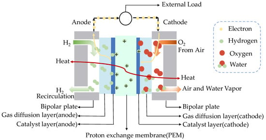
Figure 1.
The simplified model of PEMFC.
2.2. PEMFC Modeling
The Amphlett model is used here to describe the mathematical model of PEMFC [12], which comprehensively considers heat and mass transfer, energy conservation and electrochemical reaction to depict the effects of different parameters on the output characteristics of PEMFC. The fuel cell stack consists of many single cells that are assembled in series to enhance the output power and voltage. The voltage output (in V) of the PEMFC stack that comprises single cells can be calculated by (2) where the terminal voltage (in V) of each single cell can be defined by (3) based on the Amphlett model
where (in V) denotes the reversible voltage achieved in an open-circuit thermodynamic balance, as formulated by (4), which considers the stack temperature (in K) and pressure variations under the standard condition of 1 bar and 298.15 K [12].
where terms and (in atm) represent the valid partial pressures of oxygen and hydrogen, respectively. When H2 and O2 are adopted as the reactants, the partial pressures are obtained from (5) and (6). When O2 is replaced by air as the cathode reactant, the partial pressures are calculated by (5) and (7) [40].
where and represent the pressures of the cathode and anode inlet, in atm; and stand for the relative humidity of water vapor at the cathode and anode; represents the operating current of PEMFC, in A; stands for the active area of the proton exchange membrane, in cm2; is the saturated water vapor pressure, obtained through Equation (8).
represents the activation voltage drop due to the slow reaction on the active surfaces of the cathode and anode, identified by Equation (9). Among them, the semi-empirical coefficients from to possess definite physical meanings, as defined in the Butler–Volmer equation; is the dissolved oxygen concentration on the cathode catalytic interface, and it can be calculated by Henry’s Law, as shown in Equation (10).
Ohmic voltage drop can be calculated through the equivalent membrane resistance and the equivalent contact resistance . As basically demonstrates linear proportion towards current density, it can be calculated as shown below:
In Equation (11), is the ohmic voltage drop, which is linearly related to the current density, and the proportional coefficient is the sum of the equivalent contact resistance of electronic conduction and the equivalent membrane resistance . As a result of the relatively narrow operating temperature range of fuel cells, is usually regarded as a constant. To cover the entire vital PEM factors, the universal expression of Rm can be described as Equation (12)
where represents the membrane thickness, and is the hydrated membrane-specific resistivity by considering the proton flow, which is obtained by Equation (13). represents the semi-empirical parametric factor standing for the membrane water content
where is the concentration voltage formed by the concentration reduction of the fluid and resistance pressure drop during PEMFC operation, stands for the limiting current density, is the operating current density, and is the semi-empirical factor associated with the PEMFC type and operating status.
3. Multi-Strategy Tuna Swarm Optimization (MS-TSO)
3.1. An Introduction to Tuna Swarm Optimization (TSO)
Tuna is a marine carnivorous fish that feeds on various surfaces and aquatic fish, and is a top marine predator. Despite the fact that tuna swim quite fast in the ocean, their reaction speed is still slower than that of smaller, more agile fish, so tuna generally adopt a “group swimming” strategy to hunt. The TSO algorithm is enlightened by the fishing strategies of tuna’s natural foraging behavior [41]. One of the strategies is spiral foraging; while the tuna are feeding, they form a spiral shape to expel prey to shallow waters where they are more vulnerable to attack. The other strategy is parabolic foraging; each tuna follows the former tuna to form the parabola around the prey.
3.1.1. Initialization
Similar to the majority of swarm-based metaheuristics, TSO begins the optimization process by uniformly and randomly generating initial populations within the entire search space:
where stands for the ith individual matrix; and represent the lower and upper boundaries of the search space, respectively; stands for the tuna population number; and represents a homogeneously distributed random variable ranging between 0 and 1.
3.1.2. Spiral Foraging
The spiral foraging strategy is for tuna to shape a tight spiral formation for hunting. When circling to chase prey, tuna groups exchange location information with each other as well, thereby achieving information sharing between adjacent tuna groups. This strategy can be formulated by (16)–(20)
where represents the ith tuna individual in the t + 1 iteration; stands for the optimal individual in the iteration; and represent mass factors that regulate the movement of individuals towards the currently optimal individual and the former individual, respectively; is a constant used to express the degree to which the tuna follows the currently optimal individual and the previous individual; stands for the utmost iteration number; and b is a random number homogeneously distributed between 0 and 1.
When the currently optimal individual is not able to seek food, a randomized coordinate can be formed in the search space as a point of reference for the spiral search, giving TSO global exploration capabilities:
As the iteration number increases, TSO transitions from extensive global exploration in the early stages to precise local development, and the reference point of spiral foraging changes from randomized individuals to the currently optimal individual:
3.1.3. Parabolic Foraging
Apart from foraging by the spiral formation, tuna also shape a parabolic cooperative feeding. Tuna shapes a parabolic group for food as the reference point. Furthermore, tuna scrounges around for food by searching on their own. These two methods are employed concurrently, under the presumption that there is a 50% chance of selection for each. The description of the parabolic foraging mathematical model is shown as follows:
3.2. Mathematical Model of Multi-Strategy Tuna Swarm Optimization (MS-TSO)
3.2.1. Multi-Strategy Tuna Swarm Optimization
As was described in Section 3.1.2, spiral foraging has many parameters. Since each new individual needs to learn from the previous generation, the algorithm needs to independently construct the first generation of individuals, which increases the complexity of the algorithm. In short, to achieve the global optimal solution without falling into a local optimum, the complexity of the TSO algorithm will increase. To tackle this issue, a new solution combining differential evolution and subtractive evolution is created here, which produces a new generation based on the deviations of each individual, learning from the currently optimal solution and other individuals within the current population
where is the newly generated individual of the ith generation, and stand for the different individuals in the ith generation population, is the reduction factor, with an initial value is 0.7, is the influence weight of the global optimized solution on a new individual, and the initial value is 0.3. The values of and β were selected at the range of [0.1, 0.3, 0.5, 0.7, 1], and then in the 25 combinations, it was found that when values are 0.7 and β values are 0.3, the SSE is the smallest.
3.2.2. Model Solving
The primary goal of parameter identification is selecting a set of appropriate values for the unidentified factors in the mathematical model of PEMFC, so that the equivalent output voltage of the PEMFC mathematical model is equivalent to the actual PEMFC experimental test data, and the fitting error is minimized.
In Section 2.2, , , , , , , and are all operating parameters and can be measured. However, the physical parameters , , , , , , and are unknown and significantly affect the model results. Therefore, it is necessary to extract these seven parameters as accurately as possible so that the model results fit the actual measured polarization curve of the PEMFC as close as possible.
To determine the seven unidentified parameters X = {, , , , ,, }, it is necessary to define the objective function to minimize the sum of the square errors between the model-estimated voltage and the experimental voltage calculated by Equation (2) under the experimentally tested polarization curve, as shown in Equation (15). Since the seven unidentified factors in X = {, , , , ,, } have corresponding physical meanings, each parameter has a clear value range in the mathematical model, and the lower and upper limits of the corresponding parameters need to be added when the parameters are identified. The lower and upper limits of the seven unidentified factors in X are shown in Table 1
where represents the number of datasets employed for factor extraction; is the number of the experimental V-I data in each dataset; and and are the upper and lower bounds of the unidentified model parameters X, respectively.

Table 1.
Upper and lower bounds on fuel cell model factors.
A flowchart showing the application of the MS-TSO algorithm is demonstrated in Figure 2. Its step-by-step process for parameter estimation of the FEMFC model is as follows:
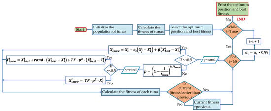
Figure 2.
Flowchart of MS-TSO algorithm.
- i.
- Initialize the maximum number of iterations and the population size, set the lower and upper bounds of the seven identified parameters, and preliminarily assign values to and in (25). Preliminarily initialize the seven parameters by taking random numbers within their respective upper and lower bounds.
- ii.
- Based on the initial values taken in i, substitute it into (2)–(14) to calculate the initial . Substitute the actual polarization curve data and the calculated V into (27) to obtain the initial objective function value, and take the minimum as the best fitness. The corresponding seven parameters are the currently optimal solution.
- iii.
- Starting from the first iteration, take a uniform random number for γ and compare it with 0.5 to indicate the probability of using (23) or (25). Then, calculate the corresponding fitness after obtaining . If the fitness is lower than the previous one, update it; if the fitness is higher than the previous one, return to the previous state.
- iv.
- Stop the loop when the maximum iteration number is reached, and output the best fitness and optimum position.
4. Results and Discussion
4.1. 25 cm2 Single Fuel Cell
To test the algorithm performance of MS-TSO, the polarization curve data obtained by the single-cell test system built by the Greenlight G20 test station were used and compared with the results of other six metaheuristic algorithms: the slime mould algorithm (SMA), differential evolution (DE), Harris hawk optimization (HHO), salp swarm optimization (SSA), particle swarm optimization (PSO), and the whale optimization approach (WOA).
To make a fair comparison with the competitive algorithms, the population size of all optimizers is set to 50; the maximum iteration number is set to 1000 and remains unchanged. Among them, the lower and upper limits of the seven factors are as specified in Table 1.
4.1.1. Introduction to the Experimental Platform
Figure 3 demonstrates the information of the Greenlight G20 fuel cell test bench used in this work. The hydrogen introduced into the anode is supplied by a hydrogen storage tank with a maximum pressure of 15 Mpa. Before entering the fuel cell, the hydrogen passes by a pressure-reducing valve to achieve a suitable pressure, and the hydrogen purity is 99.999%. The air at the cathode reaches a suitable pressure through a compressor before entering the PEMFC.
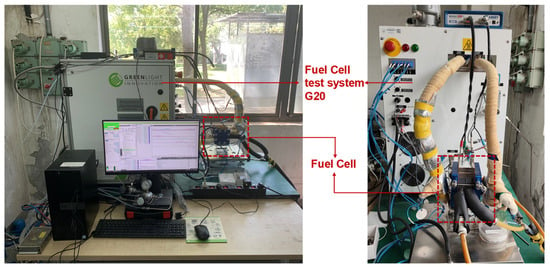
Figure 3.
The test bench of fuel cell.
The gas flow rate, pressure, and operating temperature of the PEMFC system are measured by sensors, and the inlet pressure and operating temperature of the single cell are automatically regulated by the Greenlight G20 test bench [42]. In the experimental test, in order to guarantee the reliability of the experimental data, the polarization curve test of the PEMFC is carried out in two modes according to current drop and rise. The data with a relative error of less than 1% are adopted. The physical parameters and operating conditions of the PEMFC are shown in Table 2.

Table 2.
Operating conditions and physical factors of the fuel cell used in this work.
4.1.2. Analysis of Experimental Results
The parameter-fitting process is shown in Figure 4. Compared with the competitive algorithm, the proposed MS-TSO can not only find a better global optimal solution and achieve significantly lower SSE after one thousand iterations. It can also be inferred from Figure 4 that although DE converges the fastest, followed by MS-TSO, the SSE of MS-TSO is significantly smaller than that of DE. Among them, the specific SSE and the corresponding seven parameter values of MS-TSO and the competitive algorithm after one thousand iterations are shown in Table 3.
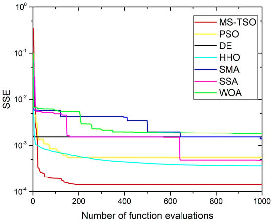
Figure 4.
Convergence curves of different algorithms for 25 cm2 single fuel cell.

Table 3.
The values of the optimized factor and SSE values achieved from different algorithms for the parameter extraction of the 25 cm2 single fuel cell.
The SSE of MS-TSO reaches 1.42963 × 10⁻⁴, which is significantly lower compared to other competing algorithms, including the PSO with an SSE of 5.5275 × 10⁻⁴, HHO with 3.6607 × 10⁻⁴, and SSA with 4.8414 × 10⁻⁴. This indicates that other competing algorithms are more prone to fall into local optimal solutions during iterations, while MS-TSO has significant advantages in exploring the global optimal solution.
The specific experimental polarization curve data and the polarization curve data calculated from the MS-TSO-based parameters are compared in Table 4. Figure 5 demonstrates the relationship between the polarization curve fitted by the optimal model parameters and the experimental data. Table 4 and Figure 5 indicate that the data obtained by the model are highly consistent with the actual polarization curve.

Table 4.
The model-simulated data and experimental V-I data of the 25 cm2 single fuel cell.
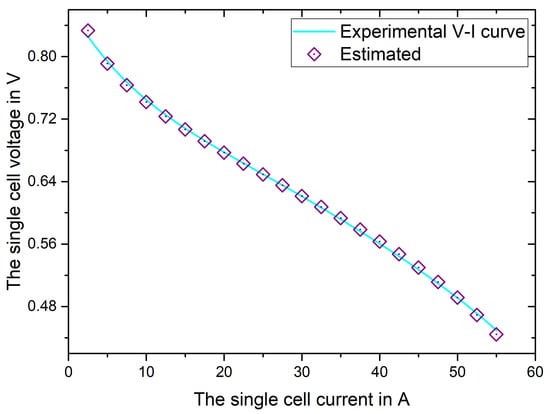
Figure 5.
Experimental and MS-TSO-based polarization curves for 25 cm2 single fuel cell.
4.2. BCS500W, NedStackPS6, and Horizon500w
In Section 4.1.2, the comparison between MS-TSO and competing algorithms using 25 cm2 single-cell polarization curve data confirmed that MS-TSO has a significant ability to balance exploration and exploitation compared to competing algorithms. To further verify the generalization ability of MS-TSO, three public datasets, BCS500W, NedStackPS6, and Horizon500w, are used to further analyze the performance of MS-TSO.
These three public datasets possess complete operating conditions and performance test data information of PEMFC, so they are widely used in parameter identification algorithm analysis. Among them, the experimental operating conditions corresponding to the three datasets are shown in Table 5, and the boundaries of the seven factors X that need to be extracted are shown in Table 1. The seven factors of the model are initialized by employing random solutions within their limits. The difference between the polarization curve data and the model is calculated in the cost function in Equation (15).

Table 5.
The operating conditions and physical factors of three PEMFC stacks.
4.3. Nedstack PS6
The variations of the SSEs of the proposed MS-TSO algorithm and its competing algorithms, with the number of iterations, are shown in Figure 6. Compared with other competitive algorithms, the MS-TSO algorithm is shown to have the characteristics of fast convergence speed and good accuracy. Among the competing algorithms, only the PSO achieves an SSE similar to the MS-TSO at the final iteration. However, MS-TSO converges to the best SSE within 100 iterations, while PSO reaches the best SSE after 800 iterations. The best SSEs of the other competing algorithms at the end of 1000 iterations are significantly larger than those of MS-TSO.
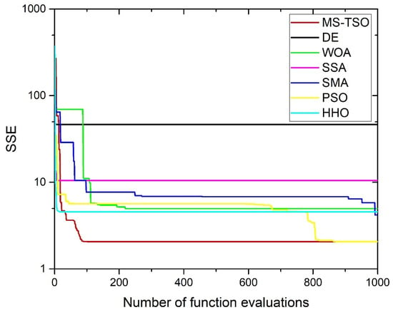
Figure 6.
Convergence curves of different algorithms for NedStackPS6.
The polarization curve data of Nedstack PS6 are shown in Table 6. There are 29 pairs of the estimated date and experimental date, and SSE is 2.0655. The polarization curves of the experimental points and estimated points of the Nedstack PS6 dataset are shown in Figure 7. The polarization curve data obtained by substituting the optimal seven parameters match the experimental polarization curve well.

Table 6.
The model-simulated data and experimental V-I data of the NedStackPS6 PEMFC stack.
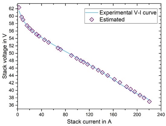
Figure 7.
Experimental and MS-TSO-based polarization curves for NedStackPS6.
The parameters estimated by the MS-TSO and other algorithms are shown in Table 7. The proposed MS-TSO has the best performance on the considered PEMFC, compared with other methods.

Table 7.
The values of the optimized factor and SSE values achieved from different algorithms for the parameter extraction of the NedStackPS6 PEMFC stack.
4.4. BCS500W
The SSE variations of the proposed MS-TSO algorithm and its competing algorithms on the fuel cell BCS500W dataset, with the number of iterations, are shown in Figure 8. Compared with other metaheuristic algorithms, the MS-TSO algorithm not only has the minimum SSE, which corresponds to the optimal values of the seven parameters but is also the fastest algorithm among the seven algorithms to reach the convergence. The polarization curve data obtained from the experiment and the MS-TSO-based data are tabulated in Table 8. The differences between the corresponding model data and the actual data at 18 measurement points are small, giving a final SSE of 0.011707.
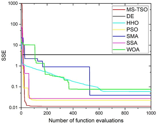
Figure 8.
Convergence curves of different algorithms for BCS500W.

Table 8.
The model-simulated data and experimental V-I data of the BCS500W PEMFC stack.
The polarization curves of the estimated points and experimental points of the BCS500W dataset are shown in Figure 9. The comparison between MS-TSO and other algorithms in the literature is demonstrated in Table 9. Among them, the SSE of MS-TSO, IABC and CSA are all around 0.0117. Compared with IABC and CSA, the SSE of MS-TSO is only slightly improved, but the SSE of the three algorithms is far smaller than that of other competitive algorithms.
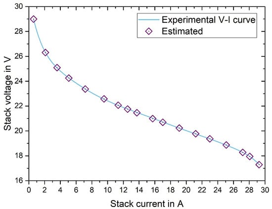
Figure 9.
Experimental and MS-TSO-based polarization curves for BCS500W.

Table 9.
The values of the optimized factor and SSE values achieved from different algorithms for the parameter extraction of the BCS500W PEMFC stack.
4.5. Horizon500W
The curves of the SSE of the proposed MS-TSO algorithm and its competing algorithms on the fuel cell harizon500w dataset, as the function of the number of iterations, are shown in Figure 10. The convergence process of different algorithms can be visualized using the convergence curves. In addition to the simulated voltage, the experimental voltage, current, and temperature values of the stack are recorded in Table 10. The comparison between MS-TSO and other algorithms in the literature is demonstrated in Table 11. The PEMFC operating temperature changes from one point to another data point in this experimental study. The total number of data points is 15, and the sum of squared errors is 0.0112. The polarization curves of the estimated points of the dataset and experimental points are shown in Figure 11. Among them, MS-TSO and WSO have similar SSE, but because the data in WSO literature are only reserved to two decimal places, it is difficult to compare the SSE of the two specifically. However, both MS-TSO and WSO have lower SSE than other competing algorithms.
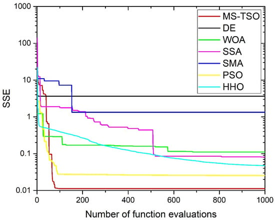
Figure 10.
Convergence curves of different algorithms for Horizon500W.

Table 10.
The model-simulated data and experimental V-I data of the Horizon500W PEMFC stack.

Table 11.
The values of the optimized factor and SSE values achieved from different algorithms for the parameter extraction of the Horizon500W PEMFC stack.
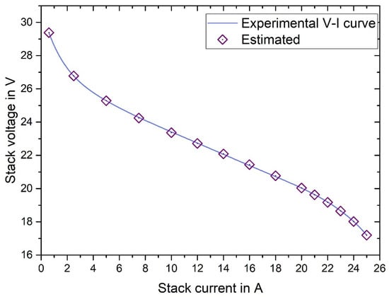
Figure 11.
Experimental and MS-TSO-based polarization curves for Horizon500W.
5. Conclusions
The polymer electrolyte membrane fuel cell (PEMFC) is one of the most promising power generation devices in the context of carbon neutrality. Due to the nonlinear characteristics of PEMFC under different operating conditions, seven parameters need to be accurately extracted to fit the polarization curves. This paper develops a multi-strategy tuna swarm algorithm (MS-TSO) to identify the unknown factors of the fuel cell model. To verify the performance of the MS-TSO, the Greenlight G20 platform was used to measure the polarization curve data of a 25 cm2 single cell with hydrogen at the anode and air at the cathode at 353 K. In terms of the set of experimental data and three different fuel cells, BCS500W, NedStackPS6 and Horizon500w are used as experimental data for the polarization curves of PEMFCs, and the sum of square errors between the model voltage and the experimental voltage is used as the objective function to be minimized.
Compared with the slime mould algorithm (SMA), differential evolution (DE), Harris hawk optimization (HHO), salp swarm optimization (SSA), particle swarm optimization (PSO), and the whale optimization approach (WOA), the results show that MS-TSO has significant advantages in convergence efficiency and accuracy.
For the 25 cm2 single cell, BCS500W, NedStackPS6 and Horizon500w datasets, the SSE of MS-TSO can reach 1.42963E-04, 0.011707, 2.0655 and 0.0112, respectively, which is significantly smaller than that of competing algorithms. Moreover, it can be found that MS-TSO can not only achieve lower SSE than competing algorithms, but also achieve the optimal SSE the fastest in the convergence curves corresponding to the four datasets. This confirms that MS-TSO has achieved a balance between exploitation and exploration. The balance between the two allows MS-TSO to have both faster convergence speed and lower SSE.
Author Contributions
Conceptualization, J.M. and X.M.; methodology, J.M. and K.S.; software, J.M., H.H. and M.A.; validation, J.M., X.M., H.L., M.A., X.T., Z.D. and J.S.; formal analysis, J.M.; investigation, J.M. and H.L.; resources, C.S.; data curation, J.M., F.F., J.J., H.L., X.M. and X.T.; writing—original draft preparation, J.M. and C.S.; writing—review and editing, J.M., C.S., H.H. and X.T.; visualization, J.M., F.F., J.J., M.A., Z.D. and J.S.; supervision, C.S., F.F., J.J. and K.S.; project administration, C.S., K.S., H.H., Z.D. and J.S.; funding acquisition, C.S., K.S. and H.H. All authors have read and agreed to the published version of the manuscript.
Funding
This work was supported in part by the National Natural Science Foundation of China under Grant 52238002, in part by the Fundamental Research Funds for the Central Universities under Grant 2022FRFK060001, in part by State Grid Corporation of China Science and Technology Project under Grant SGHLJM00HLJS2400173 in China. This work was also supported by the Researchers Supporting Project number (RSP2024R467), King Saud University, Riyadh, Saudi Arabia. The authors acknowledge also the 2023 Youth Talent Introduction Scientific Research Startup Fee (Grant No. AUGA2160100623) and 2023 Support Funds for Talent Introduction in Heilongjiang Province (Grant No. AUGA2160501723) provided by the Harbin Institute of Technology.
Data Availability Statement
The original contributions presented in the study are included in the article, further inquiries can be directed to the corresponding author.
Acknowledgement
This work was also supported by the Researchers Supporting Project number (RSP2024R467), King Saud University, Riyadh, Saudi Arabia.
Conflicts of Interest
Author Zhen Dong was employed by the company Sustainable Electrical Energy Expert China and author Jiabin Shen was employed by the company General Motors Canada. The remaining authors declare that the research was conducted in the absence of any commercial or financial relationships that could be construed as a potential conflict of interest.
References
- Sun, C.; Negro, E.; Vezzù, K.; Pagot, P.; Cavinato, G.; Nale, A.; Bang, Y.H.; Di Noto, V. Hybrid inorganic-organic proton-conducting membranes based on SPEEK doped with WO3 nanoparticles for application in vanadium redox flow batteries. Electrochim. Acta 2019, 309, 311–325. [Google Scholar] [CrossRef]
- Jiao, K.; Xuan, J.; Du, Q.; Bao, Z.; Xie, B.; Wang, B.; Zhao, Y.; Fan, L.; Wang, H.; Hou, Z.; et al. Designing the next generation of proton-exchange membrane fuel cells. Nature 2021, 595, 361–369. [Google Scholar] [CrossRef] [PubMed]
- Tang, X.; Zhang, Y.; Xu, S. Temperature sensitivity characteristics of PEM fuel cell and output performance improvement based on optimal active temperature control. Int. J. Heat Mass Transf. 2023, 206, 123966. [Google Scholar] [CrossRef]
- Chen, D.; Pei, P.; Li, Y.; Ren, P.; Meng, Y.; Song, X.; Wu, Z. Proton exchange membrane fuel cell stack consistency: Evaluation methods, influencing factors, membrane electrode assembly parameters and improvement measures. Energy Convers. Manag. 2022, 261, 115651. [Google Scholar] [CrossRef]
- Mitra, U.; Arya, A.; Gupta, S. A comprehensive and comparative review on parameter estimation methods for modelling proton exchange membrane fuel cell. Fuel 2023, 335, 127080. [Google Scholar] [CrossRef]
- Giner-Sanz, J.J.; Ortega, E.M.; Pérez-Herranz, V. Mechanistic equivalent circuit modelling of a commercial polymer electrolyte membrane fuel cell. J. Power Sources 2018, 379, 328–337. [Google Scholar] [CrossRef]
- Busquet, S.; Hubert, C.E.; Labbe, J.; Mayer, D.; Metkemeijer, R. A new approach to empirical electrical modelling of a fuel cell, an electrolyser or a regenerative fuel cell. J. Power Sources 2004, 134, 41–48. [Google Scholar] [CrossRef]
- Yang, F.; Li, Y.; Chen, D.; Hu, S.; Xu, X. Parameter identification of PEMFC steady-state model based on p-dimensional extremum seeking via simplex tuning optimization method. Energy 2024, 292, 130601. [Google Scholar] [CrossRef]
- Li, Y.; Yang, F.; Chen, D.; Hu, S.; Xu, X. Thermal-physical modeling and parameter identification method for dynamic model with unmeasurable state in 10-kW scale proton exchange membrane fuel cell system. Energy Convers. Manag. 2023, 276, 116580. [Google Scholar] [CrossRef]
- Hu, P.; Cao, G.Y.; Zhu, X.J.; Li, J. Modeling of a proton exchange membrane fuel cell based on the hybrid particle swarm optimization with Levenberg–Marquardt neural network. Simul. Model. Pract. Theory 2010, 18, 574–588. [Google Scholar] [CrossRef]
- Liu, Z.; Xu, S.; Shi, L. Research on PEMFC cathode circulation under low-load conditions and its optimal control in FCV power system for long-term durability. Int. J. Hydrog. Energy 2024, 61, 1015–1027. [Google Scholar] [CrossRef]
- Amphlett, J.C.; Baumert, R.M.; Mann, R.F.; Peppley, B.A.; Roberge, P.R.; Harris, T.J. Performance modeling of the Ballard Mark IV solid polymer electrolyte fuel cell: I. Mechanistic model development. J. Electrochem. Soc. 1995, 142, 1. [Google Scholar] [CrossRef]
- He, P.; Zhou, X.; Liu, M.; Xu, K.; Meng, X.; Yang, B. Generalized Regression Neural Network Based Meta-Heuristic Algorithms for Parameter Identification of Proton Exchange Membrane Fuel Cell. Energies 2023, 16, 5290. [Google Scholar] [CrossRef]
- El-Fergany, A.A. Electrical characterisation of proton exchange membrane fuel cells stack using grasshopper optimiser. IET Renew. Power Gener. 2018, 12, 9–17. [Google Scholar] [CrossRef]
- Gouda, E.A.; Kotb, M.F.; El-Fergany, A.A. Jellyfish search algorithm for extracting unknown parameters of PEM fuel cell models: Steady-state performance and analysis. Energy 2021, 221, 119836. [Google Scholar] [CrossRef]
- Alqahtani, A.H.; Hany, M.; Hasanien, M.A.; Sun, C. Parameters estimation of proton exchange membrane fuel cell model based on an improved Walrus optimization algorithm. IEEE Access 2024, 12, 74979–74992. [Google Scholar] [CrossRef]
- Askarzadeh, A.; Rezazadeh, A. An innovative global harmony search algorithm for parameter identification of a PEM fuel cell model. IEEE Trans. Ind. Electron. 2011, 59, 3473–3480. [Google Scholar] [CrossRef]
- Fathy, A.; Abdel Aleem, S.H.E.; Rezk, H. A novel approach for PEM fuel cell parameter estimation using LSHADE-EpSin optimization algorithm. Int. J. Energy Res. 2021, 45, 6922–6942. [Google Scholar] [CrossRef]
- Rezk, H.; Wilberforce, T.; Olabi, A.G.; Ghoniem, R.M.; Sayed, E.T.; Abdelkareem, M.A. Optimal Parameter Identification of a PEM Fuel Cell Using Recent Optimization Algorithms. Energies 2023, 16, 5246. [Google Scholar] [CrossRef]
- Ali, M.; El-Hameed, M.A.; Farahat, M.A. Effective parameters’ identification for polymer electrolyte membrane fuel cell models using grey wolf optimizer. Renew. Energy 2017, 111, 455–462. [Google Scholar] [CrossRef]
- Chen, Y.; Wang, N. Cuckoo search algorithm with explosion operator for modeling proton exchange membrane fuel cells. Int. J. Hydrog. Energy 2019, 44, 3075–3087. [Google Scholar] [CrossRef]
- Chen, Y.; Zhang, G. New parameters identification of Proton exchange membrane fuel cell stacks based on an improved version of African vulture optimization algorithm. Energy Rep. 2022, 8, 3030–3040. [Google Scholar] [CrossRef]
- Zhu, Y.; Yousefi, N. Optimal parameter identification of PEMFC stacks using adaptive sparrow search algorithm. Int. J. Hydrogen Energy 2021, 46, 9541–9552. [Google Scholar] [CrossRef]
- Sultan, H.M.; Menesy, A.S.; Hassan, M.S.; Jurado, F.; Kamel, S. Standard and Quasi Oppositional bonobo optimizers for parameter extraction of PEM fuel cell stacks. Fuel 2023, 340, 127586. [Google Scholar] [CrossRef]
- Chakraborty, U.K.; Abbott, T.E.; Das, S.K. PEM fuel cell modeling using differential evolution. Energy 2012, 40, 387–399. [Google Scholar] [CrossRef]
- Abdi, H.; Ait Messaoudene, N.; Kolsi, L.; Naceur, M.W. Modeling and optimization of a proton exchange membrane fuel cell using particle swarm algorithm with constriction coefficient. J. Therm. Anal. Calorim. 2021, 144, 1749–1759. [Google Scholar] [CrossRef]
- El-Fergany, A.A.; Hasanien, H.M.; Agwa, A.M. Semi-empirical PEM fuel cells model using whale optimization algorithm. Energy Convers. Manag. 2019, 201, 112197. [Google Scholar] [CrossRef]
- Song, Y.; Tan, X.; Mizzi, S. Optimal parameter extraction of the proton exchange membrane fuel cells based on a new Harris Hawks Optimization algorithm. Energy Sources Part A Recovery Util. Environ. Eff. 2020, 1–18. [Google Scholar] [CrossRef]
- Fathy, A.; Abdelkareem, M.A.; Olabi, A.G.; Rezk, H. A novel strategy based on salp swarm algorithm for extracting the maximum power of proton exchange membrane fuel cell. Int. J. Hydrog. Energy 2021, 46, 6087–6099. [Google Scholar] [CrossRef]
- Gupta, J.; Nijhawan, P.; Ganguli, S. Optimal parameter estimation of PEM fuel cell using slime mould algorithm. Int. J. Energy Res. 2021, 45, 14732–14744. [Google Scholar] [CrossRef]
- Zhang, B.; Wang, R.; Jiang, D.; Wang, Y.; Lin, A.; Wang, J.; Ruan, B. Parameter identification of proton exchange membrane fuel cell based on swarm intelligence algorithm. Energy 2023, 283, 128935. [Google Scholar] [CrossRef]
- Fathy, A.; Rezk, H. Multi-verse optimizer for identifying the optimal parameters of PEMFC model. Energy 2018, 143, 634–644. [Google Scholar] [CrossRef]
- Sun, S.; Su, Y.; Yin, C.; Jermsittiparsert, K. Optimal parameters estimation of PEMFCs model using converged moth search algorithm. Energy Rep. 2020, 6, 1501–1509. [Google Scholar] [CrossRef]
- Rezaie, M.; Akbari, E.; Ghadimi, N.; Razmjooy, N.; Ghadamyari, M. Model parameters estimation of the proton exchange membrane fuel cell by a Modified Golden Jackal Optimization. Sustain. Energy Technol. Assess. 2022, 53, 102657. [Google Scholar] [CrossRef]
- Rizk-Allah, R.M.; El-Fergany, A.A. Artificial ecosystem optimizer for parameters identification of proton exchange membrane fuel cells model. Int. J. Hydrog. Energy 2021, 46, 37612–37627. [Google Scholar] [CrossRef]
- Sarhani, M.; Voß, S.; Jovanovic, R. Initialization of metaheuristics: Comprehensive review, critical analysis, and research directions. Int. Trans. Oper. Res. 2023, 30, 3361–3397. [Google Scholar] [CrossRef]
- Tian, F.; Anderson, A.B. Effective reversible potential, energy loss, and overpotential on platinum fuel cell cathodes. J. Phys. Chem. C 2011, 115, 4076–4088. [Google Scholar] [CrossRef]
- Tirnovan, R.; Giurgea, S. Efficiency improvement of a PEMFC power source by optimization of the air management. Int. J. Hydrog. Energy 2012, 37, 7745–7756. [Google Scholar] [CrossRef]
- Zhang, G.; Qu, Z.; Tao, W.Q.; Wang, X.; Wu, L.; Wu, S.; Xie, X.; Tongsh, C.; Huo, W.; Bao, Z.; et al. Porous flow field for next-generation proton exchange membrane fuel cells: Materials, characterization, design, and challenges. Chem. Rev. 2022, 123, 989–1039. [Google Scholar] [CrossRef]
- Tang, X.; Zhang, Y.; Xu, S. Experimental study of PEM fuel cell temperature characteristic and corresponding automated optimal temperature calibration model. Energy 2023, 283, 128456. [Google Scholar] [CrossRef]
- Xie, L.; Han, T.; Zhou, H.; Han, B.; Tang, A. Tuna swarm optimization: A novel swarm-based metaheuristic algorithm for global optimization. Comput. Intell. Neurosci. 2021, 2021, 9210050. [Google Scholar] [CrossRef] [PubMed]
- Tang, X.; Yang, M.; Shi, L.; Hou, Z.; Xu, S.; Sun, C. Adaptive state-of-health temperature sensitivity characteristics for durability improvement of PEM fuel cells. Chem. Eng. J. 2024, 491, 151951. [Google Scholar] [CrossRef]
- Arora, S.; Anand, P. Chaotic grasshopper optimization algorithm for global optimization. Neural Comput. Appl. 2019, 31, 4385–4405. [Google Scholar] [CrossRef]
- Kandidayeni, M.; Macias, A.; Khalatbarisoltani, A.; Boulon, L.; Kelouwani, S. Benchmark of proton exchange membrane fuel cell parameters extraction with metaheuristic optimization algorithms. Energy 2019, 183, 912–925. [Google Scholar] [CrossRef]
- Cao, Y.; Li, Y.; Zhang, G.; Jermsittiparsert, K.; Razmjooy, N. Experimental modeling of PEM fuel cells using a new improved seagull optimization algorithm. Energy Rep. 2019, 5, 1616–1625. [Google Scholar] [CrossRef]
- Riad, A.J.; Hasanien, H.M.; Turky, R.A.; Yakout, A.H. Identifying the PEM Fuel Cell Parameters Using Artificial Rabbits Optimization Algorithm. Sustainability 2023, 15, 4625. [Google Scholar] [CrossRef]
- Ayyarao, T.S.L.V.; Polumahanthi, N.; Khan, B. An accurate parameter estimation of PEM fuel cell using war strategy optimization. Energy 2024, 290, 130235. [Google Scholar] [CrossRef]
Disclaimer/Publisher’s Note: The statements, opinions and data contained in all publications are solely those of the individual author(s) and contributor(s) and not of MDPI and/or the editor(s). MDPI and/or the editor(s) disclaim responsibility for any injury to people or property resulting from any ideas, methods, instructions or products referred to in the content. |
© 2024 by the authors. Licensee MDPI, Basel, Switzerland. This article is an open access article distributed under the terms and conditions of the Creative Commons Attribution (CC BY) license (https://creativecommons.org/licenses/by/4.0/).