Abstract
The process integration and electrification concept has significant potential to support the industrial transition to low- and net-zero-carbon process heating. This increasingly essential concept requires an expanded set of process analysis tools to fully comprehend the interplay of heat recovery and process electrification (e.g., heat pumping). In this paper, new Exergy Pinch Analysis tools and methods are proposed that can set lower bound work targets by acutely balancing process heat recovery and heat pumping. As part of the analysis, net energy and exergy load curves enable visualization of energy and exergy surpluses and deficits. As extensions to the grand composite curve in conventional Pinch Analysis, these curves enable examination of different pocket-cutting strategies, revealing their distinct impacts on heat, exergy, and work targets. Demonstrated via case studies on a spray dryer and an evaporator, the exergy analysis targets net shaft-work correctly. In the evaporator case study, the analysis points to the heat recovery pockets playing an essential role in reducing the work target by 25.7%. The findings offer substantial potential for improved industrial energy management, providing a robust framework for engineers to enhance industrial process and energy sustainability.
1. Introduction
Industrial process electrification is an increasingly critical pathway to minimise on-site and lifecycle greenhouse gas (GHG) emissions as national and regional grids move toward low- and net-zero-carbon renewable electricity production. Process electrification involves the complex interplay of heat and power at the process level and is commonly achieved using closed-cycle heat pumps or directly integrating gas compressors and expanders into a process. New process technologies that use electricity can also replace old process technologies that rely more on steam heating. The appropriate adoption of electrification technologies requires supporting process integration methods, such as Pinch Analysis (PA) and its derivatives, to enable their effective application.
The development of PA in the 1970s has been extensively applied within the processing industry to improve heat recovery and design more efficient industrial systems [1]. Early in its development, PA focused on the efficient use of heat energy through heat exchanger network synthesis [2], appropriate heat recovery and utility placement, and multiple process heat integration, i.e., Total Site Heat Integration [3]. Case studies using PA resulted in energy-efficient heat exchanger networks with savings between 20 and 40% being historically common [4]. In conventional PA, the concepts of Heat Pinch and the appropriate placement principle for heat pumps are sufficient to analyse system performance and determine the best integration point for a heat pump using the grand composite curve (GCC). However, as electrical/work devices become a more common process utility, the need for deeper insights into the trade-offs between heat flow and temperature increases. As a result, exergy analysis becomes increasingly critical to design an efficient utility system that relies more on electricity than conventional fuels.
Exergy analysis adds a measure for work potential to different energy forms relative to the system’s surrounding environment. It therefore provides a quantitative measure of process inefficiencies for differing energy streams [5]. The capability to determine the energy quantity of a given stream using exergy analysis therefore allows better insight into combined heat and work systems and how they should be designed and retrofitted when using existing process integration methods [6]. Exergy and electricity are closely related. Exergy represents the maximum potential for a system to perform useful work as it reaches equilibrium with the environment (dead state). The reverse is also true; exergy represents the minimum work required to increase the quality of energy in a direction away from the dead state conditions. Such work transfer can link to electricity generation or consumption, as the case may be. As a result, exergy has been applied as part of PA to understand the potential for electricity generation, consumption, and optimisation.
Exergy was first included in PA by Umeda et al. [7] using the Carnot factor (). Feng and Zhu [8] refined the Carnot factor into a more accurate exergy-to-energy ratio, which they called the energy level. Anantharaman et al. [9] followed a similar approach to produce energy-level composite curves and an energy-level GCC. However, the energy level concept often produces nonlinear composite curves, complicating their interpretation. Aspelund et al. [10] presented a succinct Extended Pinch Analysis and Design (ExPAND) method focusing on sub-ambient processes where electricity-driven refrigeration systems are the primary utility. Their analysis showed that process modifications can be made to optimise the compression and expansion work to produce the required cooling duties. Marmolejo-Correa and Gundersen [11] introduced a new Exergy Pinch Analysis that mirrored conventional PA. Their Exergy Pinch Analysis used an exergetic temperature (a transformation of normal temperature given a dead state temperature) in place of temperature and temperature-based exergy in place of enthalpy (or heat flow). These improvements enabled direct targeting of exergy requirements, deficits, and destruction for the first time. Hamsani et al. [12] later extended the concept to an exergy GCC backed by an Exergy Problem Table Algorithm.
A common challenge with all the previous forms of Exergy Pinch Analysis is the difficulty in interpreting the results (e.g., graphs) in ways that add value beyond conventional heat PA. Marmolejo-Correa and Gundersen [11] attempted to set exergy targets, but these are still at least one step removed from a meaningful work (and electricity) target that can be used as a benchmark. Hamsani et al. [12] also proposed work targets; however, as will be demonstrated in this study, these targets assume all exergy surpluses are recovered through a heat engine and all exergy deficits are fulfilled by heat pumping from ambient temperature, which is inefficient in practice. As a result, new or extended process integration methods are needed to address the challenge and opportunity presented by process electrification.
PI&E aims to harness process integration to maximise system efficiency in the context of process electrification where systems rely on electricity as the primary utility (instead of heat). Process electrification includes a range of technology solutions, such as heat pumps, electrode boilers, and electricity-driven processes, that enable the transition from fossil fuels to electricity. This concept has found strategic value for low-temperature heat industries, e.g., dairy processing [13] and food processing [14]. Complete process electrification is now economically viable for many low-temperature processes using existing technologies. However, the efficient and economical integration of electrification technology requires systematic analysis to ensure appropriate placement, operation, and design. Lincoln et al. [15] presented an iterative approach to PI&E as shown in Figure 1. This method draws on many existing process integration tools and concepts, together with process simulation, to synthesise a systematic design method. A challenging part of the method is the application and interpretation of the Exergy Pinch Analysis step in ways that provide deeper insights than heat PA alone. This study looks in more depth at how to gain such insights through an improved exergy targeting method.
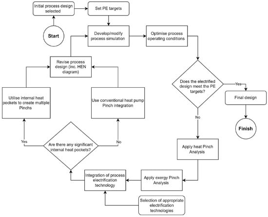
Figure 1.
Process integration and electrification (PI&E) method proposed by Lincoln et al. [15].
This paper proposes a method to calculate a minimum (lower bound) net shaft-work target that takes advantage of heat recovery pockets. By setting a meaningful net shaft-work target, the interpretation of Exergy Pinch Analysis becomes more definitive, analogous to heat PA, and useful in PI&E studies. The study analyses two case studies: a spray dryer and an evaporator. The spray dryer is a relatively simple case where the process does not contain any heat recovery pockets and the heat and exergy Pinch Points occur at an equivalent temperature. The evaporator, in contrast, is a case where there are several heat recovery pockets, and the heat and exergy Pinch Points correspond to different temperatures. A systematic investigation of heat recovery pockets on the heat and exergy GCCs provides an improved understanding of the exergy, or shaft-work, trade-offs that are inherent with these pockets from the problem during targeting.
The organisation of the paper is as follows. In Section 2, the new method for exergy targeting is presented. Focus is given to setting targets that assume the thermodynamic potential within heat recovery pockets can be realised. The method produces two sets of exergy-based targets that correspond to lower and upper bound net shaft-work targets when integrating heat engines and heat pumps into the process. Section 3 then presents two case studies. The first is a spray dryer, a case without heat recovery pockets. The second is an evaporator, a case with heat recovery pockets. These two cases illustrate how the method can apply to both cases. In case two, a range of network shaft-work targets are calculated for different levels of heat recovery pocket utilisation. Following the results section, Section 4 discusses the key challenges in using the proposed method in practice and the implications for designing a combined heat and work exchanger network. Finally, Section 5 reiterates the most significant conclusions from the study.
2. Methods
In shifting towards process electrification for energy decarbonisation, exergy can be a useful metric to evaluate and compare the efficiency of different designs [16]. PA assists in guiding the design process, simulation provides a rating of a design, while exergy is used to determine the thermodynamic inefficiencies and potentials of unit operations and streams. All three analyses are critical to gaining the insights needed to improve design.
The exergy evaluation and targeting methods in this paper follow the principles of the ExPAND method [10] and its graphical representation of Marmolejo-Correa and Gundersen [11]. An extension by Hamsani et al. [12] details how an exergy GCC can determine accurate targets for the total exergy deficit and surplus of a process system. To better understand the context of this study, the reader is encouraged to review these latter two works. Figure 2 presents the new method developed as part of this study. It builds on the work of Hamsani et al. [12]. The method has been implemented in the OpenPinch Excel Workbook, which was created by the corresponding author. The interested reader can contact the corresponding author for more details.
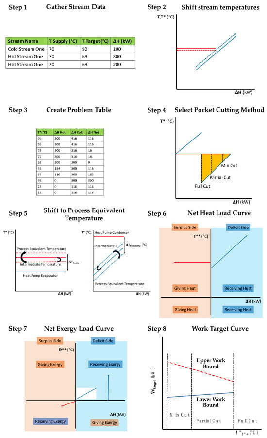
Figure 2.
Graphical outline for Exergy Pinch Analysis targeting method. Note: T* refers to shifted or intermediate temperatures, and T** refers to utility temperatures.
2.1. Stream Data Extraction
The first step is common to all process integration studies. One needs to collect hot and cold stream data for a process, including supply and target temperatures, supply, target pressures (where pressure change is significant), and heat duty. Often extracting the stream data relies on a mass and energy balance or a process simulation to ensure the temperatures and pressures are accurate. This step, often non-trivial, can be one of the most time-consuming when conducting an industrial analysis.
2.2. Initial Stream Temperature Shifts and the Problem Table
Next is to calculate the problem table, which analyses a process from the perspective of defined temperature (or exergetic temperature) intervals. All process temperatures need to shift according to a minimum approach temperature contribution, (or ), to an intermediate temperature scale, T*. Hot streams (i) are shifted down in temperature, while cold streams (j) are shifted up in temperature.
The well-established Problem Table Algorithm (PTA) can then obtain heat recovery and utility targets. Its data also underpin the graphical plots of the process CCs and GCC. As this method is standard practice, the reader who is unfamiliar with this method is referred to the Handbook of Process Integration [17].
2.3. Heat Recovery Pocket Analysis and Cutting
Using the GCC, it is necessary to identify the portions of the heat pockets intended to be used for internal heat recovery or to be used in conjunction with heat pumps or heat engines. This step represents a deviation from previous works. Hamsani et al. [12] assumed heat recovery pockets would be used for internal heat recovery only, simplifying the exergy analysis but also eliminating the potential for thermodynamic efficiency gains. They did, however, calculate the avoidable exergy destruction that occurs due to heat recovery within a pocket at temperature differences above the pre-defined minimum approach temperatures. This gave rise to the question that this study seeks to answer: what is the benefit of utilising the thermodynamic potential of the heat recovery pockets in the context of process electrification?
Heat recovery pockets represent areas on a GCC with internal process heat recovery potential. Conventionally, extended PA methods, such as Total Site Heat Integration, remove all the pockets from the process-level GCCs before Total Site Analysis. This approach is generally well justified; however, it can also miss obvious and significant energy efficiency gains when the pocket involves large temperature differences. For example, Walmsley et al. [18] demonstrated the principle of assisted heat integration using pockets to recover additional heat and generate more shaft-work.
This study investigates how different pocket cutting strategies, which represent different internal heat exchanger networks, affect the exergy and work targets. The heat recovery pocket cutting strategies, illustrated in Figure 2, include:
- Full Cut: this approach identifies and removes the full pocket from further analysis. This approach (although not referred to by this name) is commonly used in the Total Site Heat Integration method [3].
- Min Cut: this approach leaves as much of the pocket in the stream data as possible for further analysis, i.e., . This approach determines the limits for exergy and work targets providing a thermodynamic benchmark to compare against.
- Partial Cut: this approach identifies and removes the heat surplus and deficit segments of a pocket within a defined . This strategy removes part of the pocket depending on the selection of , which can be varied to understand its impact on the work targets.
A constraint for is that it must be greater than , the minimum approach temperature difference process and utility streams, i.e., . If , it indicates that transferring process heat to an intermediate utility and then to a process sink must be less thermodynamically efficient than direct process-to-process heat recovery. The Full-Cut approach sets to the maximum of the largest pocket, which is identifiable on the GCC. The Partial-Cut approach is bounded by the Full-Cut and Min-Cut approaches, representing the continuum of values in between that could be explored further to understand the selection on heat and exergy targets.
2.4. Process Temperature Equivalent Shift
Given the pocket cutting strategy, each of the remaining GCC segments are temperature-shifted back to an effective process temperature scale, , in K using a common .
The rationale for the shift back is that Carnot efficiencies for heat engines and heat pumps are based on process temperatures (as opposed to working fluid temperatures, which would be the utility temperature scale). This shift back prepares the modified GCC to be converted into net load curves.
2.5. Net Heat and Exergy Load Curves
Net load curves are introduced to split the stream segments of the modified GCC into the heat sources (left of the y-axis) and heat sinks (right of the y-axis). These curves have the same styling as Total Site Profiles [19]. The net heat load curves (NHLCs) are based on a plot of temperature and enthalpy (or heat flow).
In previous works (e.g., [12]), an exergy GCC has been proposed and applied. However, this approach struggles to universally represent all types of problems. For problems that are entirely above or below the dead state temperature, the method is adequate. However, issues arise when streams cross the dead state temperature. Above ambient temperature, heat sources are also exergy sources, while below ambient temperature, heat sinks are exergy sources. This reversal of roles means it is difficult to draw and understand an exergy GCC with streams on both sides of the dead state on a single figure. One solution is the concept of net load curves that split up sources and sinks.
To determine the net exergy load curves (NXLCs), each heat load segment needs to be translated into exergetic temperatures and exergy flows. Using the data for the heat load segments, the supply (s) and target (t) exergetic temperatures, and , and their temperature-based exergy change, , can be determined using the following equations.
where is the effective process stream temperature in K, is the dead state temperature in K, and is the heat capacity flow rate (i.e., ). Note, the is the inverse slope of segments on the modified GCC plot. Equation (6) determines only the temperature-based component of exergy, which approximates the total thermomechanical exergy (temperature and pressure) for streams with minimal pressure-based exergy, as is the case with the present study. Given the stream data for these segments, the PTA can be applied (twice) to the GCC stream segments and converted into exergy flows and exergetic temperatures to obtain an exergy-based problem table and exergy load curves. This process is repeated twice, once for all the heat surplus segments of the GCC and a second time for all the heat deficit segments of the GCC. Although the input stream data differ, the exergy-based PTA is explained step by step by Hamsani et al. [12]. The NXLC shows the amounts of surplus exergy contained in the exergy sources and deficit exergy required by the exergy sinks. In terms of the exergy analysis in this work, a dead state of 15 °C (288.15 K) and atmospheric pressure (101.325 kPa), which correspond to typical ambient conditions, has been used in the exergy analysis.
For processes that cross the dead state temperature, i.e., ambient temperature, exergy sources and sinks reverse. Above ambient temperature, hot streams are exergy sources, while cold streams are exergy sinks. Below ambient temperature, hot streams are now exergy sinks (e.g., refrigeration) and cold streams are exergy sources. In this study, the x-axis of the NXLC plot divides above and below the dead state temperature. Note, the exergetic temperatures, above or below ambient temperature, are always positive. As a result, the y-axis, both up and down, displays positive exergetic temperatures, which is critical for calculating exergy differences. The left side of the y-axis is all the exergy sources while the right side of the axis is all the exergy sinks. Note, the NXLC are original to this study.
2.6. Net Shaft-Work Calculation
This final step of the method aims to identify and calculate a net shaft-work target. The NXLC, together with the concepts of a reversible heat engine and heat pump, provides a basis for determining net shaft-work targets. A reversible (Carnot) heat engine operating between temperature levels TH and TL achieves zero entropy generation and no exergy destruction, which means,
where WHE is the reversible work generated from the heat engine, W is the heat flow from TH to TL, and X is the exergy flow from TH to TL. To obtain a meaningful work value for an actual heat engine, Equation (8) can be multiplied by a Carnot efficiency, ,
A similar analysis of a reversible heat pump and dividing by a Carnot efficiency, , gives the following relationship for the actual work of a heat pump, :
Hamsani et al. [12] applied these two equations to generate a net shaft-work target for a process,
where is the work of compression, is the work of expansion, is the exergy rejection target (below the Pinch), and is the exergy required target (above the Pinch). The Carnot efficiency, , of heat engines and heat pumps often both sit around 50% [20], justifying the equivalence of the two efficiencies in Equations (8) and (9). Targets based on a Carnot efficiency of 50% are expected, therefore, to be achievable for practical systems; however, other values for could be explored to understand its impact on the results in future studies.
In this study, the pockets on the GCC are cut using a defined strategy before the exergy analysis (another point of difference to Hamsani et al. [12]), which results in the exergy surplus and rejection targets being the same and the exergy deficit and required targets also being the same.
Equation (10) inherently assumes the exergy surplus (rejection) segments would generate work through a heat engine and the exergy deficit (required) segments would consume work using a heat pump from the specified dead state. As a result, Equation (10) may substantially overestimate the actual work of a well-designed system since a heat pump supplied by exergy surplus segments would be more efficient than applying a heat engine and then a heat pump in series.
An improved shaft-work target, representing a lower bound, would supply heat pump devices with as much of the exergy (and heat) surpluses (S) as possible to fulfil exergy (and heat) deficits (D), while any remaining exergy surplus segments would be recovered through a heat engine. As a result, this study defines as the fraction of heat surplus segments supplying heat pump devices (as opposed to heat engine devices). Given different values, net shaft-work targets can be determined using
where is an exergy deficit segment on the NXLC and is an exergy surplus segment on the NXLC.
The Full-Cut strategy would result in only exergy deficits above the Pinch and exergy surpluses below the Pinch, and Equation (9) is equivalent to Equation (8) when given . In contrast, setting gives a lower bound net shaft-work target that represents an ideally designed system of heat pump and heat engine devices given the defined minimum approach temperatures, pocket cutting strategy, and Carnot efficiency.
3. Case Studies
3.1. Spray Dryer Case Study
This case study delves into the operation of a spray dryer employed in the production of milk powder. The primary function of the dryer is to transform milk concentrate, which is derived from evaporation lines, into a powdered state. This case study was initially presented by Liang et al. [21]. The stream data and the process flow diagram are found in Table 1 and Figure 3.

Table 1.
Stream data for the spray drying system.
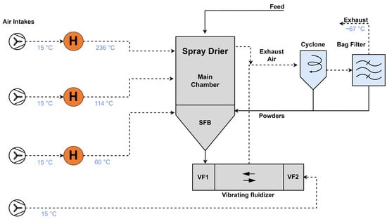
Figure 3.
Flow diagram of the spray drying process.
In the drying process, the feed is initially atomized and exposed to the hot air from the main air chamber at 236 °C. Moving to the bottom of the chamber, a static fluid bed (SFB) is utilised for additional drying, using a separate air stream at 114 °C. Subsequently, the partially dried powder exits through a series of vibrating fluidised (VF) beds, which provide ample residence time to complete the drying process. The exhaust air streams from the main chamber and fluid beds merge before entering the cyclone and bag filter.
3.2. Milk Evaporator Case Study
The base case design, shown in Figure 4, is a two-effect mechanical vapour recompression (MVR) milk evaporator system with a milk heat treatment system derived from Walmsley et al. [22]. The original design was modified to include a second flash vessel immediately before milk enters the first effect to increase preheating efficiency [15].
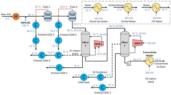
Figure 4.
Milk evaporator process flow diagram.
The process takes 247 t/h of raw milk, which is sufficient to produce 30 t/h of milk powder product. The raw milk is heated from 8 °C to 95 °C using heat recovery, which is followed by Direct Steam Injection (DSI) to reach the desired temperature and to achieve rapid heating and low residence times to maintain high product quality. After preheating, two flash cooling steps produce low-pressure vapour that can be used for additional heat recovery. Milk then enters the evaporator with Effect 1, which has a mean temperature driving force of 4 °C, and Effect 2, which maintains a mean temperature driving force of 7 °C, with both MVRs upgrading vapour to 72 °C (saturation). The flash vessels and evaporators produce condensate and vapour streams that have heat recovery potential. Beyond the evaporation process, ancillary services, such as milk chilling and cleaning in place (CIP), require on average 1155 kW of additional heating duty and 456 kW of cooling duty. These hot and chilled water demands fluctuate with time and require heat storage to be integrated with the evaporation system.
In this study, the milk evaporation system is considered in isolation to define a fully electric milk evaporator system. The stream data are presented in Table 2. In the future, it is anticipated that placing the milk evaporator system in the context of Total Site Heat Integration may lead to additional performance gains [19].

Table 2.
Stream data for the milk evaporator system.
4. Results
The results comprise the analysis of two case studies: a milk spray dryer and a milk evaporator plant. The milk spray dryer case, with a simpler GCC, does not contain heat recovery pockets. As a result, it also serves as a good illustration of the basic method. The milk evaporator case study is more complicated due to the presence of heat recovery pockets on the GCC and that it includes streams on both sides of the dead state conditions. These case studies demonstrate how the method can be applied to a wide range of processes and sites.
4.1. Spray Dryer Analysis and Results
In the spray dryer case study, the exhaust air contains a large amount of excess heat that could be optionally cooled to ambient temperature and utilised for heat recovery and as a heat source for the heat pump. As shown in Figure 5, the GCC has no pockets, and indicates a hot utility target of 4.98 MW and a cold utility target of 3.99 MW.
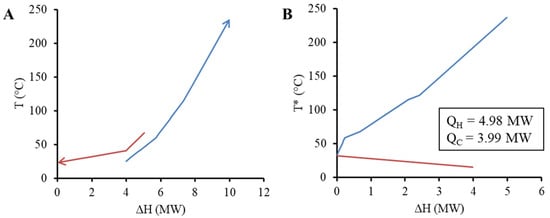
Figure 5.
Composite curve, CC, (A) and grand composite curve, GCC, (B) for the milk powder spray dryer system. Note: T* refers to shifted or intermediate temperature scale.
In this case, the absence of heat pockets leads to NHLC (Figure 6A) without overlap, and the curves are equivalent to each of the regions of the GCC. This indicates that there is no further potential for heat recovery. Additionally, since the entire GCC is above the dead state temperature, the NHLC and NXLC (Figure 6B) appear similar in shape. However, the relative magnitudes of sources to sinks differ substantially. The sources close to the dead state contain minimal exergy, resulting in a change in proportions. Despite the lower temperature and therefore lower exergy content of the excess heat available, utilising this heat as a heat source for the heat pump system can still improve its performance and reduce the necessary work shaft for the electrification of the process.
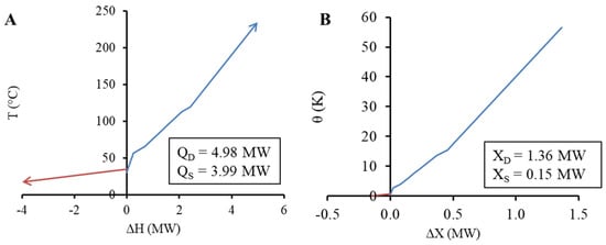
Figure 6.
Net heat load curve (A) and net exergy load curve (B) for the milk powder spray dryer system.
Assuming an exergetic efficiency of 50%, the resulting work targets vary from 2.42 MW () to 2.65 MW () using Equation (11). The case assumes that the excess heat below the Pinch temperature is fully expanded to the dead state and the heat demand above the Pinch is supplied by a heat pump utilizing the dead state as a source. On the other hand, the case sets a lower bound that assumes that exergy is utilised, avoiding exergy destruction associated with expansion and compression to and from the dead state.
4.2. Evaporator Analysis
The evaporator system is significantly different from the spray dryer. As shown in Figure 7, this system contains three heat recovery pockets, where one is considerably larger than the other two. As a result, this subsection explores various strategies for cutting the heat recovery pockets and their impact on the utility demand.
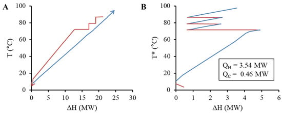
Figure 7.
Composite curves (A) and GCC (B) for the milk evaporator system, where red segments identify hot streams and/or heat surpluses and blue segments identify cold streams and/or heat deficits. Note: T* refers to shifted or intermediate temperature scale.
4.2.1. The Full and Minimum Pocket Cutting Strategies
This paper introduces the concept of a as part of the energy and exergy analysis. The “Full-Cut” pocket strategy assumes all pockets are used for internal process heat recovery (Figure 8). While this may save energy, there is a thermodynamic penalty that results in exergy destruction during the heat recovery process, especially in cases where the [12]. Figure 8A shows that the NHLCs do not overlap, indicating that the maximum heat recovery has been reached. The Pinch range is found between 5.5 and 10.5 °C, with most heating for the evaporator required between 90 and 100 °C. In this case, the Exergy Pinch in Figure 8B sits in the same corresponding exergetic temperature band.
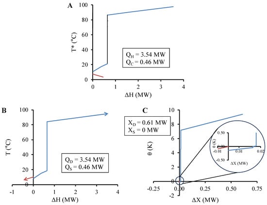
Figure 8.
GCC (A), net heat load curve (B), and net exergy load curve (C) for the milk evaporator system based on the Full-Cut pocket strategy. Note: T* refers to shifted or intermediate temperature scale. Note: T* refers to shifted or intermediate temperature scale.
At the other extreme, the “Min-Cut” strategy (Figure 9) leaves as much of the pocket in the energy and exergy analysis as possible that may find benefit through indirect heat recovery or heat pumping schemes. In this study, = 5 °C, and this second shift accounts for the general need to transfer heat to and from an intermediate fluid, e.g., a heat pump refrigerant. This value also defines the lower limit of , i.e., 5 °C, as is equal to or greater than . In Figure 9A, the effect of is visible as the vertical black lines in the 60–90 °C temperature range where three ends of pockets have been cut. In this case, there is a significant overlap on the temperatures of the NHLC, indicating potential for heat recovery. In Figure 9B, the temperatures of each segment are shifted and then converted to exergetic temperatures and exergy flow.
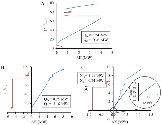
Figure 9.
GCC (A), net heat load curve (B), and net exergy load curve (C) for the milk evaporator system based on the Min-Cut pocket strategy (5 °C cut). Note: T* refers to shifted or intermediate temperature scale.
Pockets with a small amount of potential exergy destruction (Xpd) have limited opportunity to improve thermodynamic efficiency beyond internal heat recovery. Pockets with a large amount of exergy destruction can present additional opportunities to improve thermodynamic efficiency while also electrifying the process with electric technologies such as heat pumps. If the large bottom pocket is assumed to be recovered through heat exchange (Full Cut), the associated exergy destruction would reach 200 kWx. The total impact of cutting versus minimally cutting the pockets is evident also in comparing the exergy targets as net values (deficits minus surpluses). Compared to the Full-Cut strategy, the Min-Cut strategy achieves a lower exergy deficit requirement above the Pinch and a lower surplus target below the Pinch in this case. This leads to, assuming an exergy efficiency of 50%, minimum shaft-work targets of 1.21 MW and 0.54 MW for the Full-Cut and Min-Cut strategies, respectively.
4.2.2. Partial-Cut Pocket Strategy
In between the extremes of the Full-Cut and Min-Cut strategies is the Partial-Cut strategy. Higher values result in more of the pocket being removed and an inherent acceptance of more exergy destruction within the internal heat recovery network. As one further example, Figure 10 presents the results for the cutting pocket with a of 20 °C. The exergy deficit is the same as the Min-Cut strategy, while the exergy surplus decreases from 0.168 MW (Min Cut) to 0.141 MW, where the gap of 0.027 MW is lost to exergy destruction during additional internal process heat recovery.
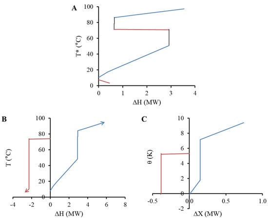
Figure 10.
GCC (A), net heat load curve (B), and net exergy load curve (C) for the milk evaporator system based on the Partial-Cut pocket strategy (20 °C cut). Note: T* refers to shifted or intermediate temperature scale.
4.2.3. Analysis of the Pocket-Cutting Strategy on Net Shaft-Work Targets
As mentioned, the variable has specific lower and upper limits, representing the Min-Cut and Full-Cut approaches, respectively. This study has calculated targets within these limits to better understand the observed trends. Figure 11 shows the impact of on the net shaft-work targets (i.e., red and blue lines). These targets are determined using Equation (9). For this case, the amount of exergy surpluses is negligible under the Min-Cut strategy, which results in the convergence of the two sets of work targets.
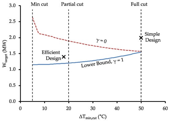
Figure 11.
Net shaft-work targets for a range of values, including both simple and efficient design points. The simple design and efficient design points are taken from the work of Lincoln et al. [15].
The label “simple design” in Figure 11 corresponds to a heat pump placement across the pinch temperature and would be in accordance with conventional pinch analysis strategies. First, the pockets are cut via heat integration, and the remaining heat utility is supplied by a single, high-temperature lift heat pump operating from ambient temperature to 105 °C. Due to the high-temperature lift, the resulting COP falls to 2.1.
The label “efficient design” corresponds to the design developed by Lincoln et al. [15]. The “efficient design” involved the placement of heat pumps around both Pinch regions to generate a practical process design that approaches the minimum work consumption (Figure 11). By leveraging smaller temperature lifts, the “efficient design” was able to raise the combined COP of the system to 3.17.
The practicality of a design is determined by many factors that are specific to a process but could include spatial layout, scheduling, and operability. Increasing the practicality generally acts to counter efficiency and therefore moves away from the minimum work target. For example, in the “efficient design”, streams of different temperature levels ranging between 68 and 74 °C were combined, which increased the amount of exergy destruction in the system but reduced the number of heat exchangers required.
5. Interpretation and Implications of the Exergy Analysis on Design Decisions
It is important to recognise the value added by exergy PA, and particularly the lower bound work target, to conventional heat PA. The lower bound shaft-work target establishes a thermodynamic benchmark to compare the quality of a system’s performance.
The net heat load curves and net exergy load curves are useful representations of the actual heat and exergy available as heat sources for heat pump integration. The inclusion of the heat pockets of the GCC with this method reduces the minimum exergy target, which highlights the importance of avoiding exergy destruction, which can sometimes be substantial for internal process (i.e., direct) heat recovery in the heat pockets. Integrating heat pumps in these heat pockets may appear counter to the conventional rules of Pinch Analysis because it increases the apparent heating and cooling utility targets. However, as shown, the net shaft-work requirement based on a practical level of exergy efficiency (50%) can decrease. To achieve the lower work target, multiple heat pumps need to be integrated into the processes.
The relationship between direct heat recovery on the heat pockets and the use of these pockets for heat pump integration can also be considered. Where pockets are cut out of the GCC (and therefore not present in the exergy analysis), the inherent assumption is that the heat source/sink segments will be matched as conventional process heat. If a pocket (or any portion of it) is left in the analysis, the exergy analysis assumes that a heat pump and/or heat engine could utilise its thermodynamic potential. By investigating different strategies for cutting the heat pockets, the trade-off between the solution with higher exergy efficiency (smaller value) and the solution with simpler system design (larger value) can be explored. The decision variable encapsulates the general trade-off between capital and energy, i.e., simple inefficient design vs. complex efficient design. An efficient system design will consider the complexity of the system and the necessary investment, as well as the energy efficiency, resulting in a partial cut of the pocket.
Lastly, the presented method also highlights the importance of utilising excess heat as a heat source for the heat pumps rather than using a direct expansion device when setting exergy targets, as shown by the difference in the results with different gamma factors. The results show that the use of the available exergy as a heat source for heat pumping should be prioritised, as it avoids the additional exergy destruction of the expansion.
The use of the gamma factor avoids the application of the exergy efficiency factor for streams that are used as a heat source and are not expanded to the dead state temperature for minimum work targeting. However, when the available excess heat is found above the dead state temperature and is utilised by a heat pump, the exergy efficiency factor considered with this method does not represent the actual efficiency of the heat pump, since it is dependent on the dead state temperature. The use of a Carnot or Lorenz efficiency factor, which considers the source temperature instead of the dead state temperature, may be better fitted to represent the work targets for heat pump integration [23].
Net load curves underline the heat pockets’ significance in establishing exergy targets and demonstrate the benefits of an efficient pocket-cut strategy when integrating multiple heat pumps. However, further investigation into optimally combining sink and source streams is necessary for an efficient system design.
6. Conclusions
This study focussed on refining the application of Exergy Pinch Analysis for targeting the efficient conversion of industrial process heating to renewable electricity through the utilisation of heat recovery pockets.
The investigations performed during the study led to the proposal of two concepts as additions to Exergy Pinch Analysis:
- An improved work targeting equation (Equation (11)), which includes a new gamma factor, that enables determination of a practical minimum work target. Gamma indicates the proportion of available surplus heat utilised by heat pumps while the remainder is expanded to the dead state. Future work can look further into the role of gamma and how its selection is best made for additional case studies where heat sinks are the limiting factor.
- The heat and exergy grand composite curves and the net energy and exergy load curves are used to visualise available energy and exergy within heat pockets, giving different perspectives and aiding targeted energy optimisation. Different pocket-cutting strategies can be investigated as a result. Such strategies significantly impact heat and exergy targets, showcasing various implications on system design.
These methods were applied to two case studies: a milk powder spray dryer system and a milk evaporator. In the case of the milk evaporator case study, it was shown that the lower boundary of the net shaft-work target escalates proportionally with the removal of more heat recovery pockets. The difference between the minimum work target (i.e., maximum utilisation of heat recovery pockets) and maximum work target (i.e., no utilisation of heat recovery pockets) is 400 kW, corresponding to 25.7%. Additionally, the case study illustrated scenarios where the heat and exergy analyses’ Pinch points were manifested in distinct temperature ranges. The optimal solution implied placing heat pumps around both Pinch regions, defying the conventional rules of Pinch Analysis.
Author Contributions
Conceptualisation, T.G.W.; methodology, T.G.W. and B.J.L.; software T.G.W.; formal analysis, T.G.W., B.J.L. and R.P.; investigation, T.G.W., R.P., and B.J.L.; data curation, T.G.W., B.J.L. and R.P.; writing—original draft preparation, T.G.W.; writing—review and editing, D.J.C.; visualisation, T.G.W., B.J.L. and R.P.; funding acquisition, T.G.W. and D.J.C. All authors have read and agreed to the published version of the manuscript.
Funding
This research was funded by the programme “Ahuora: Delivering sustainable industry through smart process heat decarbonisation”, an Advanced Energy Technology Platform, funded by the New Zealand Ministry of Business, Innovation and Employment.
Data Availability Statement
The data that support the findings of this study are available from the corresponding author, T.G.W., upon reasonable request.
Conflicts of Interest
The authors declare no conflicts of interest.
Abbreviations
| Symbol | Description |
| CC | Composite Curve |
| CIP | Cleaning in Place |
| COP | Coefficient of Performance |
| CP | Heat Capacity |
| DSI | Direst Steam Injection |
| EPTA | Exergy Problem Table Algorithm |
| GCC | Grand Composite Curve |
| MVR | Mechanical Vapour Recompression |
| NHLC | Net Heat Load Curve |
| NXLC | Net Exergy Load Curve |
| PA | Pinch Analysis |
| PI&E | Process Integration and Electrification |
| PTA | Problem Table Algorithm |
| SFB | Static Fluidised Bed |
| T* | Shifted Temperatures |
| VFB | Vibrating Fluidised Bed |
| W | Work |
| γ | Fraction of heat surplus segments supplying heat pump deficits |
| ∆Tcont | Contribution to the approach temperature (°C) |
| ∆Tmin | Minimum approach temperature |
| ∆Tmin,cut | Delta T to achieve a minimum pocket cut |
| ∆Tmin,U | Minimum utility approach temperature |
| ∆X | Change in exergy |
| ηII | Carnot efficiency |
| θ | Exegetic temperature |
| τ | Effective process temperature |
References
- Klemeš, J.J.; Varbanov, P.S.; Walmsley, T.G.; Jia, X. New Directions in the Implementation of Pinch Methodology (PM). Renew. Sustain. Energy Rev. 2018, 98, 439–468. [Google Scholar] [CrossRef]
- Gundersen, T. 4—Heat Integration: Targets and Heat Exchanger Network Design. In Handbook of Process Integration (PI); Klemeš, J.J., Ed.; Woodhead Publishing Series in Energy; Woodhead Publishing: Sawston, UK, 2013; pp. 129–167. ISBN 978-0-85709-593-0. [Google Scholar]
- Dhole, V.R.; Linnhoff, B. Total Site Targets for Fuel, Co-Generation, Emissions, and Cooling. Comput. Chem. Eng. 1993, 17, S101–S109. [Google Scholar] [CrossRef]
- Hackl, R.; Harvey, S. Total Site Analysis (TSA) and Exergy Analysis for Shaft Work and Associated Steam and Electricity Savings in Low Temperature Processes in Industrial Clusters. Chem. Eng. Trans 2012, 29, 73–78. [Google Scholar]
- Kotas, T.J. The Exergy Method of Thermal Plant Analysis; Paragon Publishing: Trowbridge, UK, 2012; ISBN 978-1-908341-89-1. [Google Scholar]
- Khaliq, A.; Kaushik, S.C. Thermodynamic Performance Evaluation of Combustion Gas Turbine Cogeneration System with Reheat. Appl. Therm. Eng. 2004, 24, 1785–1795. [Google Scholar] [CrossRef]
- Umeda, T.; Harada, T.; Shiroko, K. A Thermodynamic Approach to the Synthesis of Heat Integration Systems in Chemical Processes. Comput. Chem. Eng. 1979, 3, 273–282. [Google Scholar] [CrossRef]
- Feng, X.; Zhu, X.X. Combining Pinch and Exergy Analysis for Process Modifications. Appl. Therm. Eng. 1997, 17, 249–261. [Google Scholar] [CrossRef]
- Anantharaman, R.; Abbas, O.S.; Gundersen, T. Energy Level Composite Curves—A New Graphical Methodology for the Integration of Energy Intensive Processes. Appl. Therm. Eng. 2006, 26, 1378–1384. [Google Scholar] [CrossRef]
- Aspelund, A.; Berstad, D.O.; Gundersen, T. An Extended Pinch Analysis and Design Procedure Utilizing Pressure Based Exergy for Subambient Cooling. Appl. Therm. Eng. 2007, 27, 2633–2649. [Google Scholar] [CrossRef]
- Marmolejo-Correa, D.; Gundersen, T. New Graphical Representation of Exergy Applied to Low Temperature Process Design. Ind. Eng. Chem. Res. 2013, 52, 7145–7156. [Google Scholar] [CrossRef]
- Hamsani, M.N.; Walmsley, T.G.; Liew, P.Y.; Wan Alwi, S.R. Combined Pinch and Exergy Numerical Analysis for Low Temperature Heat Exchanger Network. Energy 2018, 153, 100–112. [Google Scholar] [CrossRef]
- Bühler, F.; Zühlsdorf, B.; Nguyen, T.-V.; Elmegaard, B. A Comparative Assessment of Electrification Strategies for Industrial Sites: Case of Milk Powder Production. Appl. Energy 2019, 250, 1383–1401. [Google Scholar] [CrossRef]
- Atuonwu, J.; Tassou, S. Decarbonisation of Food Manufacturing by the Electrification of Heat: A Review of Developments, Technology Options and Future Directions. Trends Food Sci. Technol. 2021, 107, 168–182. [Google Scholar] [CrossRef]
- Lincoln, B.J.; Kong, L.; Pineda, A.M.; Walmsley, T.G. Process Integration and Electrification for Efficient Milk Evaporation Systems. Energy 2022, 258, 124885. [Google Scholar] [CrossRef]
- Munir, M.T.; Young, B.R.; Yu, W. Can Exergy Be a Useful Tool for the Dairy Industry? In Proceedings of the 24th European Symposium on Computer Aided Process Engineering-ESCAPE 24, Budapest, Hungary, 18 June 2014; Elsevier B.V.: Amsterdam, The Netherlands, 2014; pp. 1129–1134. [Google Scholar]
- Abd Manan, Z.; Alva-Argaez, A.; Arsenyeva, O.P.; Bandyopadhyay, S.; Berntsson, T.; Bogataj, M.; Bonhivers, J.-C.; Bulatov, I.; Chin, H.H.; Czamara, M.; et al. List of Contributors. In Handbook of Process Integration (PI), 2nd ed.; Klemeš, J.J., Ed.; Woodhead Publishing Series in Energy; Woodhead Publishing: Sawston, UK, 2023; pp. xvii–xx. ISBN 978-0-12-823850-9. [Google Scholar]
- Walmsley, T.G.; Atkins, M.J.; Tarighaleslami, A.H.; Liew, P.Y. Assisted Heat Transfer and Shaft Work Targets for Increased Total Site Heat Integration. Chem. Eng. Trans. 2016, 52, 403–408. [Google Scholar] [CrossRef]
- Walmsley, T.G.; Atkins, M.J.; Ong, B.H.Y.; Klemeš, J.J.; Walmsley, M.R.W.; Varbanov, P.S. Total Site Heat Integration of Multi-Effect Evaporators with Vapour Recompression for Older Kraft Mills. Chem. Eng. Trans. 2017, 61, 265–270. [Google Scholar] [CrossRef]
- Arpagaus, C.; Bless, F.; Uhlmann, M.; Schiffmann, J.; Bertsch, S.S. High Temperature Heat Pumps: Market Overview, State of the Art, Research Status, Refrigerants, and Application Potentials. Energy 2018, 152, 985–1010. [Google Scholar] [CrossRef]
- Liang, J.; Andersen, M.P.; Solé, R.P.I.; Bellemo, L.; Bergamini, R.; Poulsen, J.L.; Zühlsdorf, B.; Schneider, P.; Jensen, J.K.; Markussen, W.B.; et al. Full Electrification Opportunities of Spray Dryers in Milk Powder Processes. In Proceedings of the ECOS 2022-The 35th International Conference on Efficiency, Cost, Optimization, Simulation and Environmental Impact of Energy Systems 2022, Copenhagen, Denmark, 3–7 July 2022. [Google Scholar]
- Walmsley, T.G.; Atkins, M.J.; Walmsley, M.R.W.; Philipp, M.; Peesel, R.-H. Process and Utility Systems Integration and Optimisation for Ultra-Low Energy Milk Powder Production. Energy 2018, 146, 67–81. [Google Scholar] [CrossRef]
- Lior, N.; Zhang, N. Energy, Exergy, and Second Law Performance Criteria. Energy 2007, 32, 281–296. [Google Scholar] [CrossRef]
Disclaimer/Publisher’s Note: The statements, opinions and data contained in all publications are solely those of the individual author(s) and contributor(s) and not of MDPI and/or the editor(s). MDPI and/or the editor(s) disclaim responsibility for any injury to people or property resulting from any ideas, methods, instructions or products referred to in the content. |
© 2024 by the authors. Licensee MDPI, Basel, Switzerland. This article is an open access article distributed under the terms and conditions of the Creative Commons Attribution (CC BY) license (https://creativecommons.org/licenses/by/4.0/).