Article

Study of Performance Changes in Centrifugal Compressors Working in Different Refrigerants

Danfoss Turbocor Compressors, Tallahassee, FL 32310, USA
*
Author to whom correspondence should be addressed.
Energies 2024, 17(11), 2784; https://doi.org/10.3390/en17112784
Submission received: 18 May 2024 / Revised: 31 May 2024 / Accepted: 4 June 2024 / Published: 6 June 2024
(This article belongs to the Section J: Thermal Management)

Abstract

:
Centrifugal compressors are commonly used in heating, ventilation, and air conditioning (HVAC) systems. The current generation of refrigerants in HVAC systems have very low ozone depletion potential, but most of them are still considered as containing high global warming potential (GWP) chemicals. Facing the regulatory pressure to eliminate the high-level GWP refrigerants, some of the existing HVAC systems will need to switch to low-GWP refrigerants. In this paper, we studied the performance changes in a refrigerant centrifugal compressor when switching from R134a to R1234ze(E) and R1234yf through a method that combined numerical simulation and an 1D meanline code. By combining these two methods, a reliable compressor performance change prediction was generated using limited results from the computational fluid dynamics (CFD) simulations. The results show that the property differences in the working fluid can significantly change the refrigerant compressor performance, including the compressor efficiency, pressure ratio, power consumption, working range and cooling capacity.

1. Introduction

As global warming intensifies, the record-breaking warmth of November 2023 coupled with other above-normal temperature months in 2023 has led to 2023 being designated as the hottest year since 1940, as reported by Copernicus [1] and the World Meteorological Organization [2]. The first generation refrigerants (CFCs) and second generation refrigerants (HCFCs) have contributed to the depletion of the ozone layer and were phased out by regulations [3,4]. The transition from the third generation to the fourth generation mandated by the regulations represents a move towards refrigerants with lower global warming potential (GWP) refrigerants. In line with these changes, the widely used third generation refrigerant R134a (GWP = 1330) will be replaced by its alternatives with lower GWPs, with R1234ze(E) (referred to as R1234ze in this study) (GWP = 6) and R1234yf (GWP = 4) as two of the primary options [5,6]. Within the refrigeration system, the compressor serves as the core component that creates the necessary pressure increase for the cooling cycle. Centrifugal compressors are gaining more popularity for their superior efficiency and compact design. These compressors are usually designed and optimized for a specific refrigerant under predefined conditions to maximize their efficiency [7,8,9]. Therefore, the analysis to understand the performance changes when submitting the working fluid of R134a with R1234ze or R1234yf is crucial to ensure that chiller systems can still efficiently deliver the required cooling or heating capacity, while minimizing the need for extensive upgrades to the system hardware [10,11,12].
A number of papers have been published on the compressor and chiller system performance changes when using low-GWP refrigerant as a drop-in replacement for R134a. Sethi [13] studied the system performance change in a small vending machine equipped with a fixed speed, reciprocating compressor. The analysis showed that the R1234yf can have a similar cycle efficiency as R134a due to their similar condensing temperature while R1234ze will have a lower cycle efficiency due to its higher condensing temperature, although the system components like the heat exchanger can be optimized to improve the R1234ze cycle efficiency. In a reciprocating-type heat pump case study, Luigi [14] investigated the use of R1234ze and R1234yf as drop-in replacements for R134a. The study considered both a fixed compressor speed configuration and a fixed heating capacity configuration. Both R1234ze and R1234yf exhibited a decline in both heating capacity and efficiency with R1234ze affected more significantly than R1234yf in the configurations. Li [15] also noted a 20% coefficient of performance (COP) drop and a 5% drop in volumetric efficiency when replacing R134a with R1234yf in a refrigerant system with a linear compressor. Alptug [16] performed a system-level exergy analysis in a vapor compression system to compare the performance difference among R134a, R1234ze, and R1234yf. The results shows both R1234ze and R1234yf are a good fit as a drop-in replacement for R134a, while the R1234ze showed higher system efficiency than R1234yf. Aized’s [17,18] thermodynamic analyses in an automobile air conditioning system indicated a substantial COP decrease for R1234yf across various compressor speeds compared to R134a. Gang [19] studied the performance changes in a two-stage centrifugal chiller when switching from R134a to several different low-GWP refrigerants. Because of the low density of R1234ze, it will exhibit a 25% volume capacity reduction in comparison with the baseline using R134a and therefore the compressor size needs to be increased to reach the same level of cooling capacity as R134a. Park [20] proposed a method to predict the performance change in a two stage centrifugal compressor when replacing the original working fluid R134a with R1234ze and R1233ze(E). The method provided good accuracy for R1234ze but high discrepancies for R1233ze(E). Yi [21] performed the CFD study on a single stage centrifugal compressor. With the same saturated suction temperature (SST), saturated discharge temperature (SDT), and cooling capacity, the COP of the R1234ze was reduced by about 5%, while the R1234yf experienced a greater reduction of approximately 9% compared to the R134a.
Overall, the research on centrifugal compressors with varying refrigerants remains limited with some of the conclusions being questionable, particularly when the COP is calculated based on the constant capacity, which ignores the fact that the compressor’s optimal capacity should be changed accordingly when the refrigerant changes. This paper explores the performance dynamics of a two-stage centrifugal compressor when transitioning between R134a, R1234ze, and R1234yf, using a blend of high-fidelity computational fluid dynamics (CFD) simulations and the 1D meanline method. The high-fidelity CFD simulations establish critical anchor points for the calibration of the 1D meanline model, which in turn allows for rapid assessments of compressor performance under various operational conditions. Given the expected changes in maximum capacity with different refrigerants, this study focuses on overall performance variations across different conditions rather than focusing solely on a single point.
The structure of the remainder of this paper is as follows: Section 2 evaluates the basic thermodynamic properties of the three refrigerants and their theoretical impact on compressor performance. Section 3 details the setups and validations of the high-fidelity CFD models and explains the 1D meanline calibration. In Section 4, the compressor performance, as predicted by the calibrated 1D meanline model, is presented along with a discussion on the observed performance changes. The main conclusions are summarized in Section 5.

2. Thermodynamic Analysis

Figure 1 depicts the pressure–enthalpy (p-h) diagrams for the three refrigerants, with thermodynamic properties sourced from NIST Refprop 9.1 [22]. Among them, R134a exhibits the highest critical pressure, while R1234yf demonstrates the lowest. At a given SST, both R134a and R1234yf share similar suction pressures, whereas R1234ze presents a lower value. The operation envelope of the compressor in the refrigeration cycle is largely dependent on the SST and SDT, which are governed by the evaporator and condenser temperature. The temperature–enthalpy (T-h) diagram, as shown in Figure 2, indicates that R1234ze can achieve the highest SDT, while R1234yf achieves the lowest. The max SDT impacts the compressor’s efficacy in a heat pump application and the difference indicates that R1234yf cannot achieve the same hot water temperature as R134a and R1234ze. When the temperature is below the critical temperature of R1234yf, R1234yf has the lowest latent heat, with R134a having the highest among the three refrigerants. With the same mass flow rate, condenser subcooling temperature, and compressor suction superheat, the cooling capacity provided by the compressor is proportional to their latent heat.
Since the heating/cooling capacity of a centrifugal compressor is dependent on its choke flow, which is a function of the volumetric flow, the volumetric cooling capacity is computed from the latent heat at a particular temperature. The relationship is illustrated in Figure 3 using R134a as the baseline. It shows that regardless of the operating mode, R1234ze’s volumetric capacity is consistently less than that of R134a, suggesting potential limitations in achieving maximum capacity comparable to R134a. R1234ze’s volumetric capacity surpasses that of R134a at temperatures below 0 °C, but drops below it when the temperature is above 0 °C, which suggests that R1234yf has the potential to provide a higher cooling capacity for the low temperature applications than R134a when requiring a sub 0 °C SST, but a lower cooling capacity in the comfort cooling application which usually requires the above 0 °C SST.
Additionally, the speed of sound in the working fluid is a critical parameter in turbomachinery performance. Figure 4 details the variation in sound speed for the three refrigerants under saturated gas conditions at various temperatures. The speed of sound influences the corrected speed of the compressor, which in turn is critical in determining the compressor’s pressure ratio and maximum mass flow rate.
Figure 5 illustrates the enthalpy–entropy (h-s) diagram for the compression process, considering the two stages as an integrated unit. In this diagram, conditions 1 and 2 denote the inlet and discharge states of the compressor, respectively, while 0 means the stagnation condition of the flow.
In this analysis, the total-static pressure ratio (π) and total-static efficiency (η) serve as primary metrics and are delineated in Equations (1) and (2), respectively. The flow factor, FF, is employed to quantify the compressor’s mass flow rate in a non-dimensional form. The definition of the compressor’s corrected speed is explained in Equation (4), which incorporates a01, the speed of sound at the compressor inlet under total flow conditions. For reasons of commercial sensitivity, the efficiency, speed, pressure ratio, SDT, and the flow factor will be normalized by a random uniform scaling factor in the subsequent parts of this study.
π = P 2 P 01
η = h 2 s h 01 h 02 h 01
F F = m ˙ 1 a 01 ρ 01
N c = N a 01
The performance of a centrifugal compressor can be represented by a set of six non-dimensional parameters, as depicted in Equation (5). On the right-hand side of the equation, the first term inside the parenthesis represents the blade Mach number, followed by a modified version of the flow factor, then the Reynolds number, and concluding with the isentropic pressure–volume exponent characteristic of the fluid. Equation (6) characterizes the isentropic work conducted by the compressor and serves as a tool to assess the influence of these parameters [7,23,24].
P 02 P 01 , η = f ( N d a 1 ,   m ˙ ρ 01 a 01 d 2 , ρ 01 N d 2 μ , γ p v )
h 02 s h 01 = a 01 2 γ P v 1 [ P 02 P 01 γ P v 1 γ P v 1 ]

3. Methodology

Developing a performance map for a compressor traditionally involves extensive experimental tests or computational fluid dynamics (CFDs) simulations, which both take a significant quantity of resources. To expedite this process, this study employs a hybrid method that integrates CFD simulation results with the 1D meanline method to create a compressor performance map with satisfactory engineering precision. For each refrigerant, CFD simulations cover three speed lines with limited points per speed line. Subsequently, a 1D meanline model based on the key geometry parameters of the compressor is calibrated using CFD data. This calibrated 1D model then generates an expanded compressor map with additional speed lines and points.

3.1. Compressor Geometry and Test Tig Information

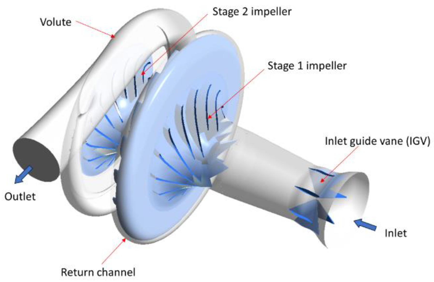
The focus of this study is a two-stage centrifugal compressor. Both stages feature impellers with seven main blades and a set of splitters, as illustrated in Figure 6. Both stages employ the vaneless diffuser after the impellers. Post-impeller, each stage employs a vaneless diffuser, and a return channel fitted with 19 guide vanes links the stages. Following the second stage, the flow converges into a tongue-less volute. Figure 7 presents the assembly of the compressor’s primary components. Due to the commercial sensitivity, no detailed geometry information is available for this study.

3.2. CFD Modeling

The test rig schematic is shown in Figure 8A and the CFD simulation’s flow domain is depicted in Figure 8B. A gas cycle test rig is employed to establish the compressor performance benchmark. The pressure and temperature are measured at the compressor suction and discharge location. The ASHRAE standards are the reference for the flow parameter measurement. The mass flow rate is measured on the liquid line. For the CFD domain, the primary flow path comprises the inlet, both stage impellers and diffusers, the return channel, and the volute. The inlet to the first stage also integrates the inlet guide vane (IGV) structure, which remains fully open for all simulations. To align the CFD simulation with actual experimental configurations, secondary flow paths for both stages accommodate the front and rear leakage flows. The periodic conditions are applied to the inlet, the impeller, the vaneless diffuser, the return channel, and all the leakage flow channels to reduce the computational resource consumption. All the periodic domains are discretized with hexahedral elements while the volute domain is meshed with tetrahedral elements. Figure 9 shows the mesh on the first stage impeller. The overall flow domain consists of 5.8 million nodes and 12.7 million elements. The y+ is below 10 on the blade surface for all the simulated speeds. The mesh settings are adopted from a prior published study for a similar compressor [25] and no further meshing sensitivity studies were performed due to the similarity of both the geometry and operating conditions between the previous studied compressor and the current compressor.
The CFD simulation is performed in Ansys CFX with steady state simulation and a k-omega shear stress transport (SST) turbulence model. The impeller domains are set as rotating, and the rest of the components are set as stationary. A mixing plane interface is used between the rotating and stationary stations. The front leakage channels connect the diffuser to the corresponding stage inlet. The rear seals inlets are set as the interface with the diffuser and the outlets are set as the outlet with static pressure and temperature identical to the first stage inlet. The leakage flow channel surfaces that meet the impeller shroud are rotating at the impeller rotating speed. The other component walls are set as stationary. The component interfaces employ a mixing plane approach. The total pressure and temperature are applied to the compressor first stage inlet and the mass flow rate boundary conditions are applied to the volute outlet. The inlet total temperature is set as 15.5 °C while the inlet total pressure is set as the saturated pressure at 5.5 °C for all three refrigerants, which are 356 kPa, 264 kPa, and 379 kPa for R134a, R1234ze, and R1234yf, respectively. With the described inlet temperature, the refrigerant will have 10 °C of superheat to avoid the condensation situation in the simulation.

3.3. CFD Model Validation and Compressor Speed Line Expansion

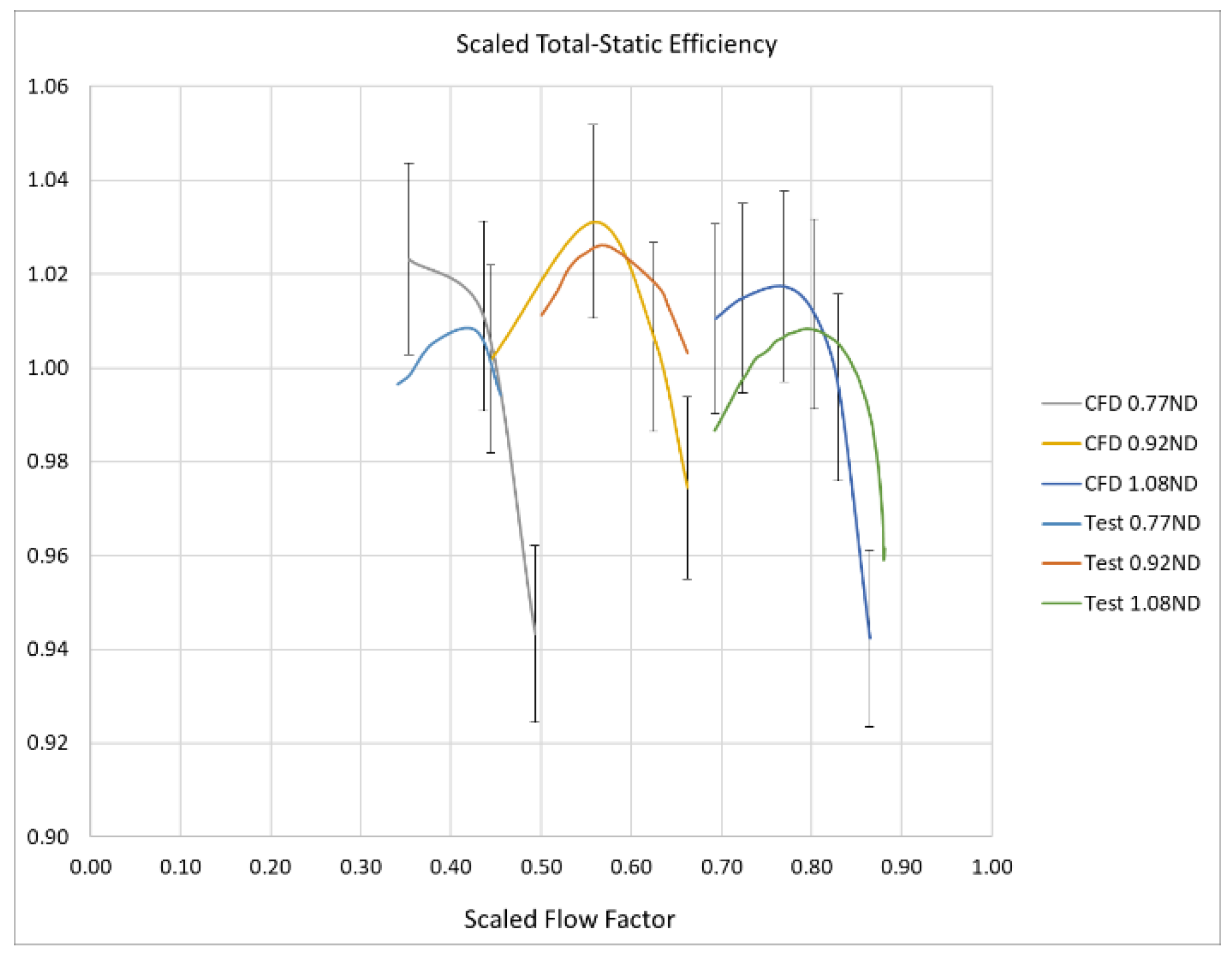
Figure 10 and Figure 11 compare the CFD results for R1234ze against the experimental data. The CFD data include a 2 percent error margin. Both the pressure ratio and the efficiency align closely with the test data, and thus the CFD provides sufficient accuracy for engineering applications.

3.4. The 1D Meanline Modal Calibration and Compressor Speed Line Expansion

The 1D meanline model conceptualizes each compressor component—impeller, diffuser, volute, etc.—as a control volume and employs the general thermodynamic calculations together with empirical correlations and loss models to predict the compressor performance [26]. By adjusting the loss and deviation coefficients within the 1D model, the model can be calibrated to capture the specific compressor performance with a high accuracy [27,28]. In this study, the 1D meanline model of the compressor is built in a commercial turbomachinery software TurboTides 8.8 [29]. Because the significant property changes among the three refrigerants, the 1D model is calibrated with the CFD results of each refrigerant to achieve a higher accuracy than the calibration based on one single refrigerant. For each refrigerant, the CFD results at a rotating speed of 0.77 ND, 0.92 ND, and 1.08 ND are used for calibration purposes, where ND represents the designed speed of the compressor.
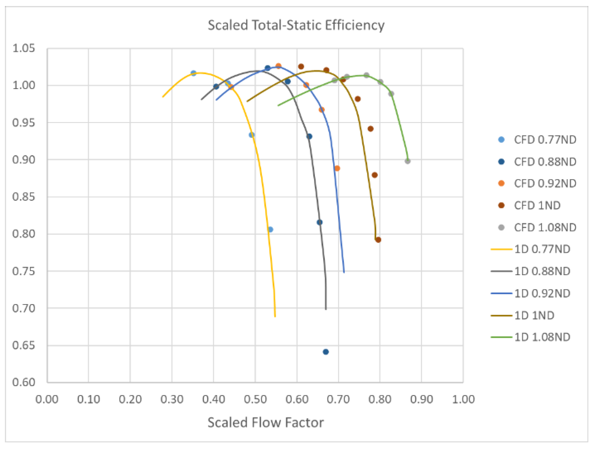
Figure 12 and Figure 13 show the comparison of the compressor pressure ratio and efficiency between the CFD results and the calibrated 1D model predictions for R1234ze. The figures 0.77 ND, 0.92 ND, and 1.08 ND are the speed lines at which the 1D model is calibrated, while the 0.88 ND and 1 ND speed lines are 1D model predictions where it is not calibrated. At the calibrated speed lines, the 1D model predictions exactly match the CFD results. At the 0.88 ND and 1 ND speed lines, the calibrated 1D model still provides the compressor performance prediction with a satisfactory precision for engineering objectives. The three calibrated 1D models facilitate the following analysis of the compressor performance map across a speed range from 0.77 ND to 1.08 ND, increasing in increments of 0.04 ND.

4. Results and Discussion

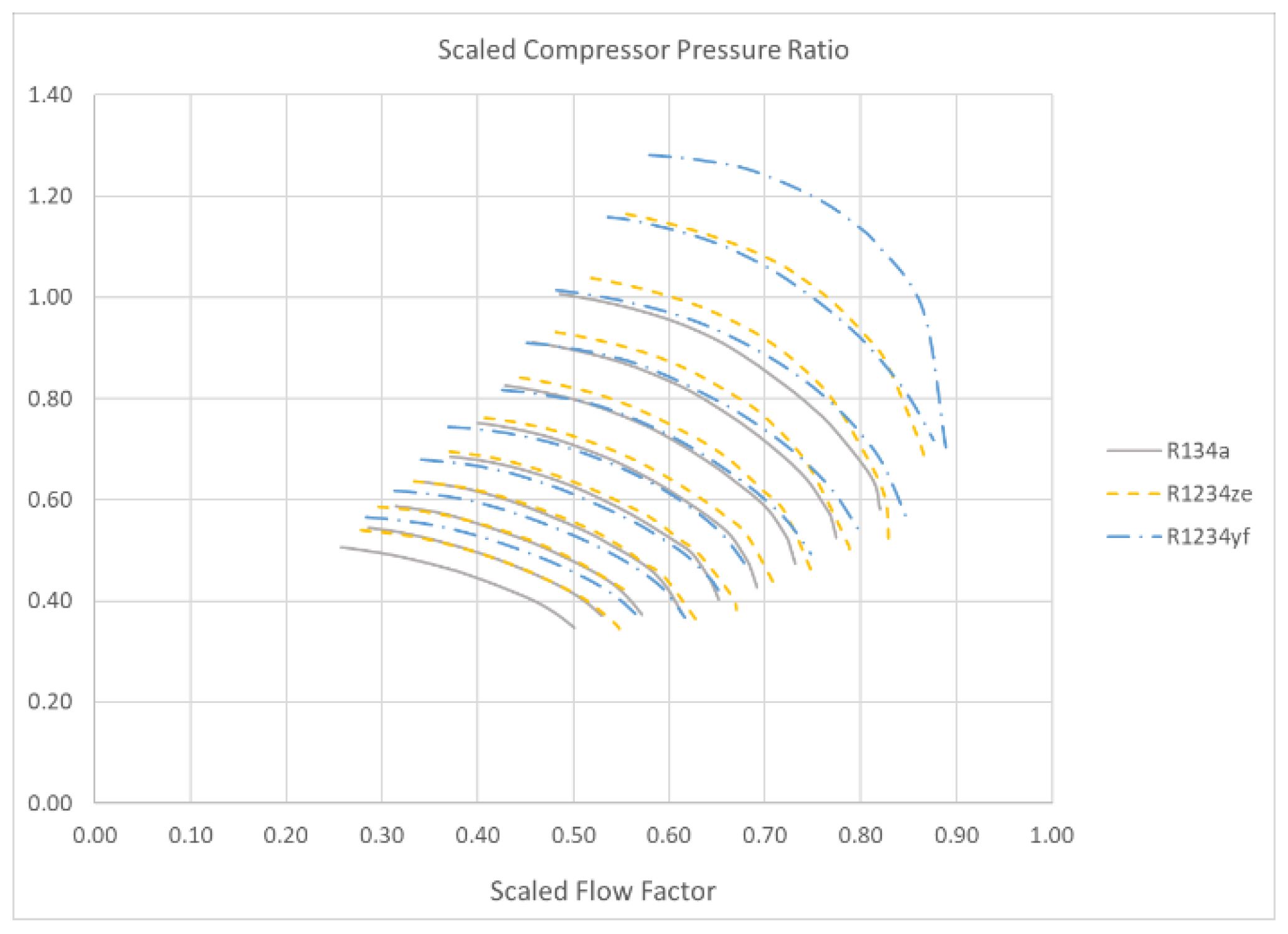
Figure 14 displays a comparison of compressor pressure ratios for R134a, R1234ze, and R1234yf at speeds ranging from 0.77 ND to 1.08 ND with a 0.04 ND increments. At equivalent speeds and flow factors, R1234yf consistently achieves the highest pressure ratio, with R1234ze in the middle, and R134a at the lowest pressure. As shown in Equation (5), the compressor needs to be working at a similar corrected speed, rather than the actual speed, to achieve the similarity. Due to R1234yf’s lower speed of sound at the inlet, it possesses the highest corrected speed, suggesting that the compressor operates at a relatively higher speed with R1234yf compared to R134a and R1234ze. Thus, the significant pressure ratio difference among the refrigerants is attributed to the variations in corrected speeds, as shown in Figure 15.
Another critical consideration in refrigerant substitution is the SDT. In cooling applications, the maximum SDT defines the highest ambient temperature a compressor can handle, whereas in heating applications, it determines the maximum hot water temperature that can be supplied. Figure 16 presents the scaled compressor SDT with the three refrigerants with the air-cooled and water-cooled chiller full-load typical SDT line marked, which is the AHRI 2023 standard-required SDT for an air-cooled chiller and water-cooled chiller. With the current speed range, R134a barely maintains a functional working range, while R1234ze and R1234yf offer a broad operating range. At 1.08 ND speed, the maximum achievable scaled SDTs are 4.5 for R1234yf, 3.9 for R1234ze, and 3.5 for R134a. R1234yf’s higher max SDT enables it to function in extremely hot conditions and to provide higher heated water temperatures in heat pump applications.
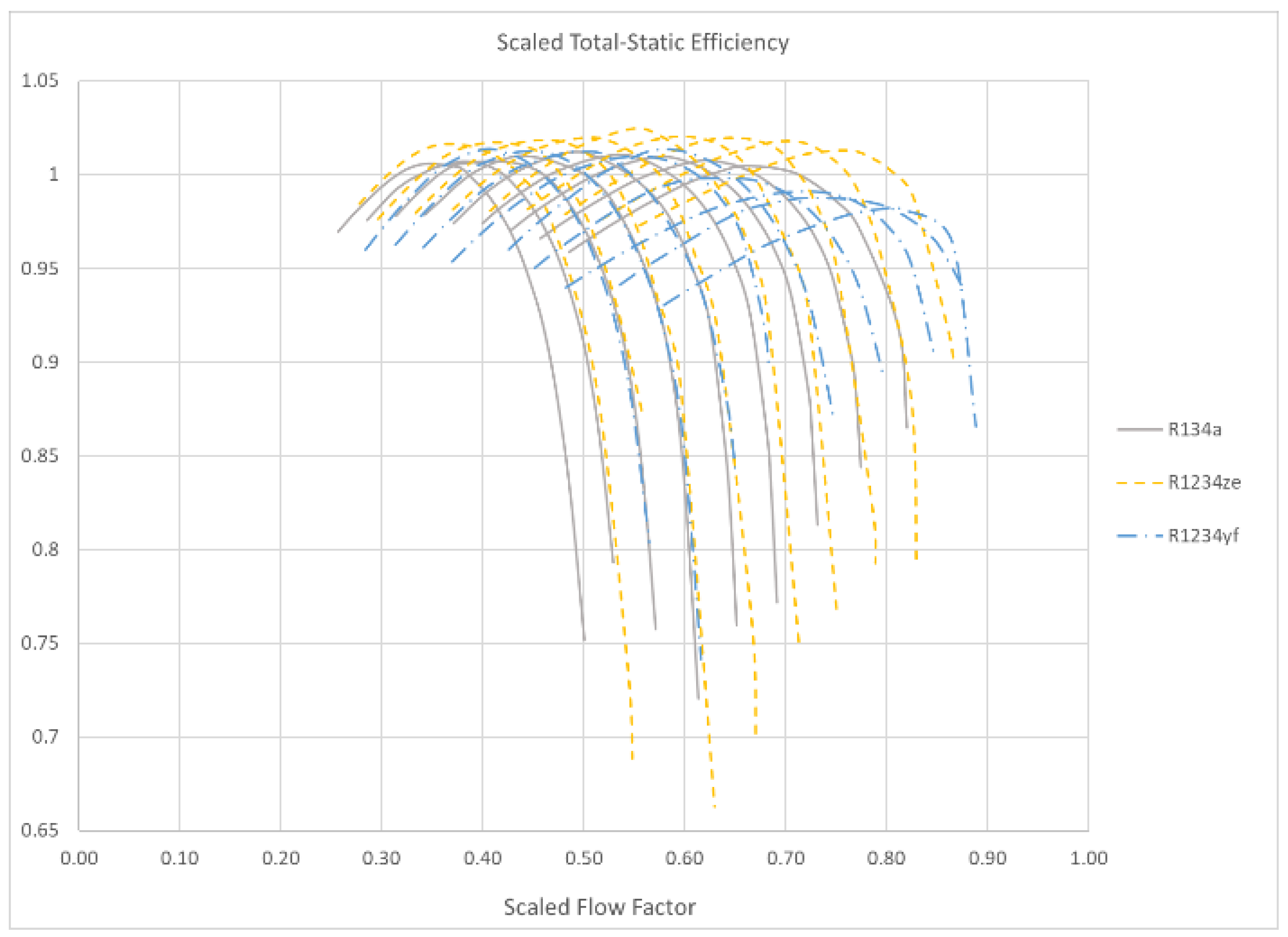
Figure 17 plots the total-static isentropic efficiency of the compressor against the flow factor. R1234ze demonstrates the highest overall efficiency, with R134a and R1234yf generally exhibiting similar levels.
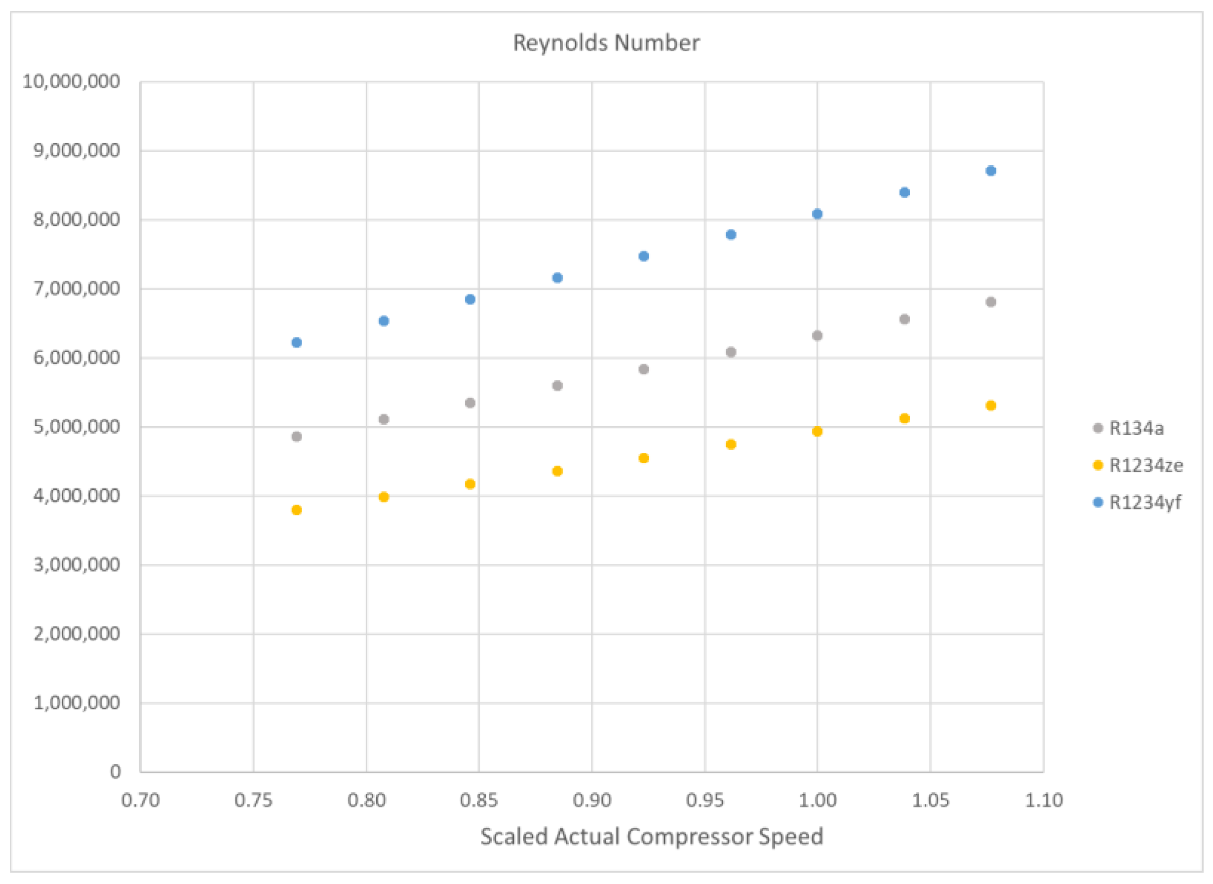
The compressor total-static isentropic efficiency against the corrected inlet mass flow rate is plotted in Figure 17. The R1234ze shows overall higher efficiency than the other two refrigerants, while R134a and R1234yf show generally the same level of efficiency. With fixed flow factors, pressure ratios, and corrected speeds, Equation (5) indicates that the peak efficiency differences can be caused by the Reynolds number and isentropic exponent difference. Prior studies have suggested that higher Reynolds numbers and larger isentropic exponents can improve the compressor efficiency [23,24,27,30,31,32,33]. However, R1234ze has the lowest Reynolds number in the studied speeds, as shown in Figure 18. Additionally, the isentropic exponents for R134a, R1234ze, and R1234yf are 1.06, 1.04, and 1.02, respectively, at the inlet condition, indicating that R1234ze’s heightened efficiency may be attributed to a blend of fluid properties rather than a single characteristic. Comparing this observation in this study to the lower efficiency of R1234ze in a single stage compressor presented in Yi’s study [21], the specific compressor geometry may also contribute to the varying efficiency and further studies in the future should reveal more details. Other issues related to the turbomachinery performance changes when switching the refrigerants, including surge behavior changes, operating pressure ratio changes, etc., should also be addressed [34,35].
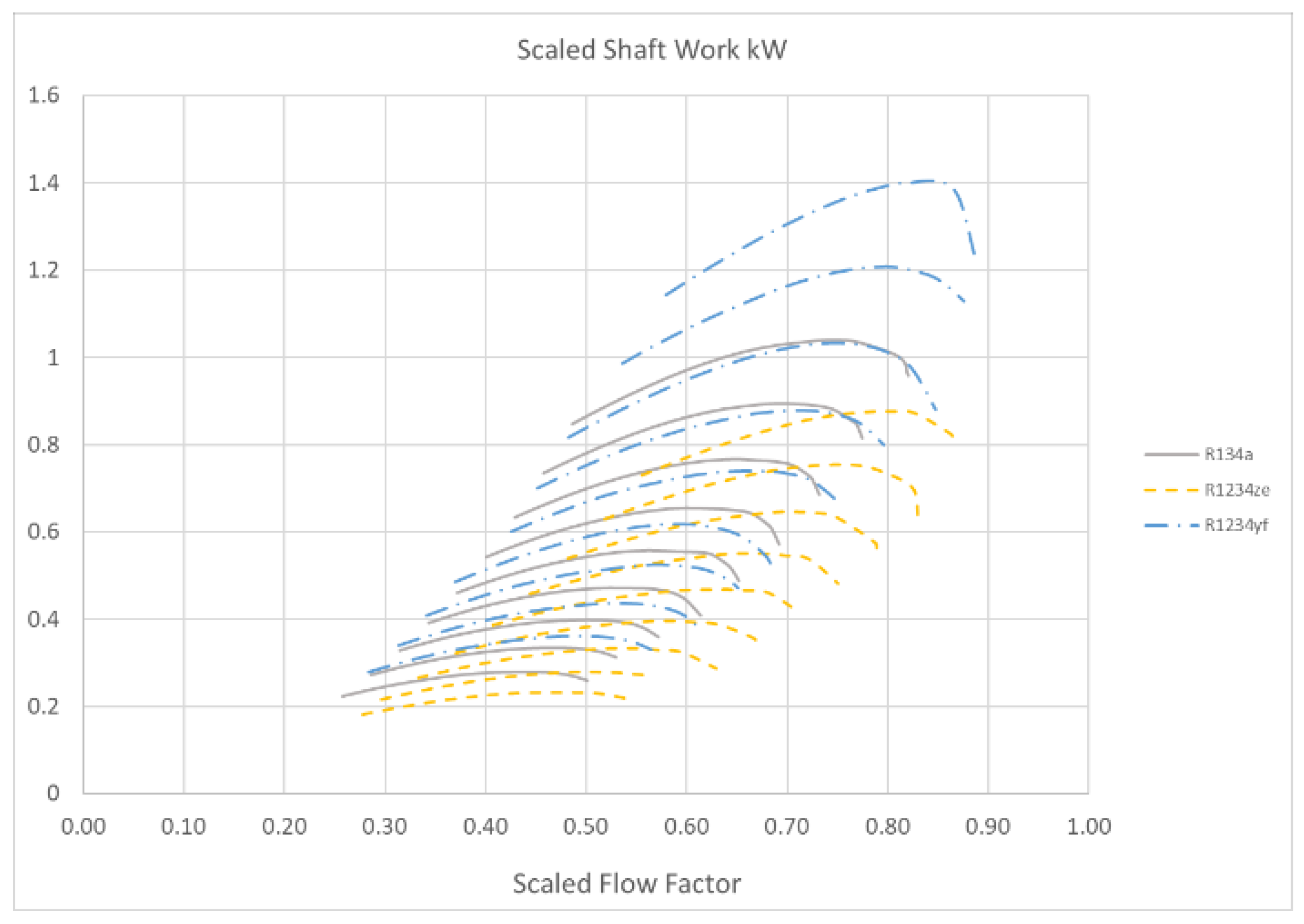
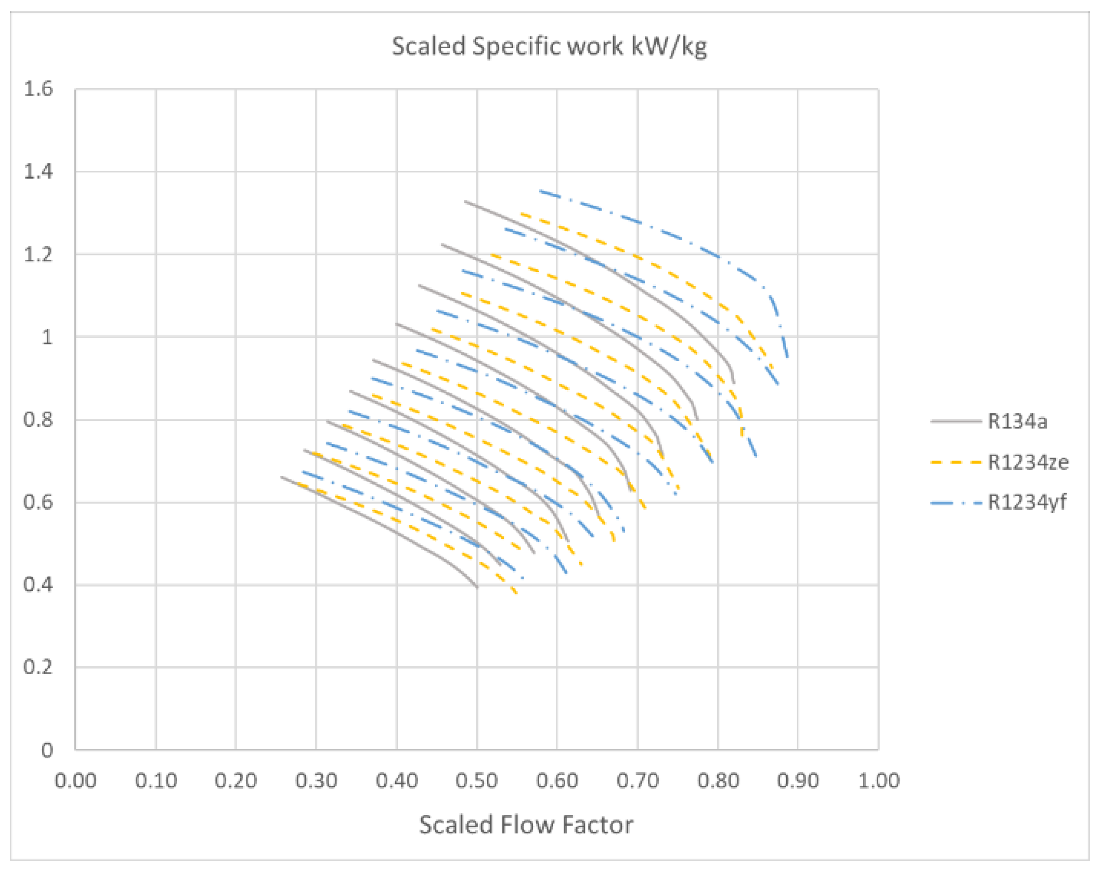
The compressor power consumption is plotted against the flow factor in Figure 19. At 1.08 ND, R1234yf consumes the highest power, followed by R134a, while R1234ze uses the least power. This indicates that a driving motor designed for R134a and R1234ze may not deliver the power needed for R1234yf to run at the same max speed. The compressor power consumption is the result of multiplying the mass flow rate and the specific enthalpy change, and the specific enthalpy change is the enthalpy difference between the inlet total condition and the outlet total condition. The specific power consumption is plotted in Figure 20 and mass flow rate vs. the flow factor is plotted in Figure 21.
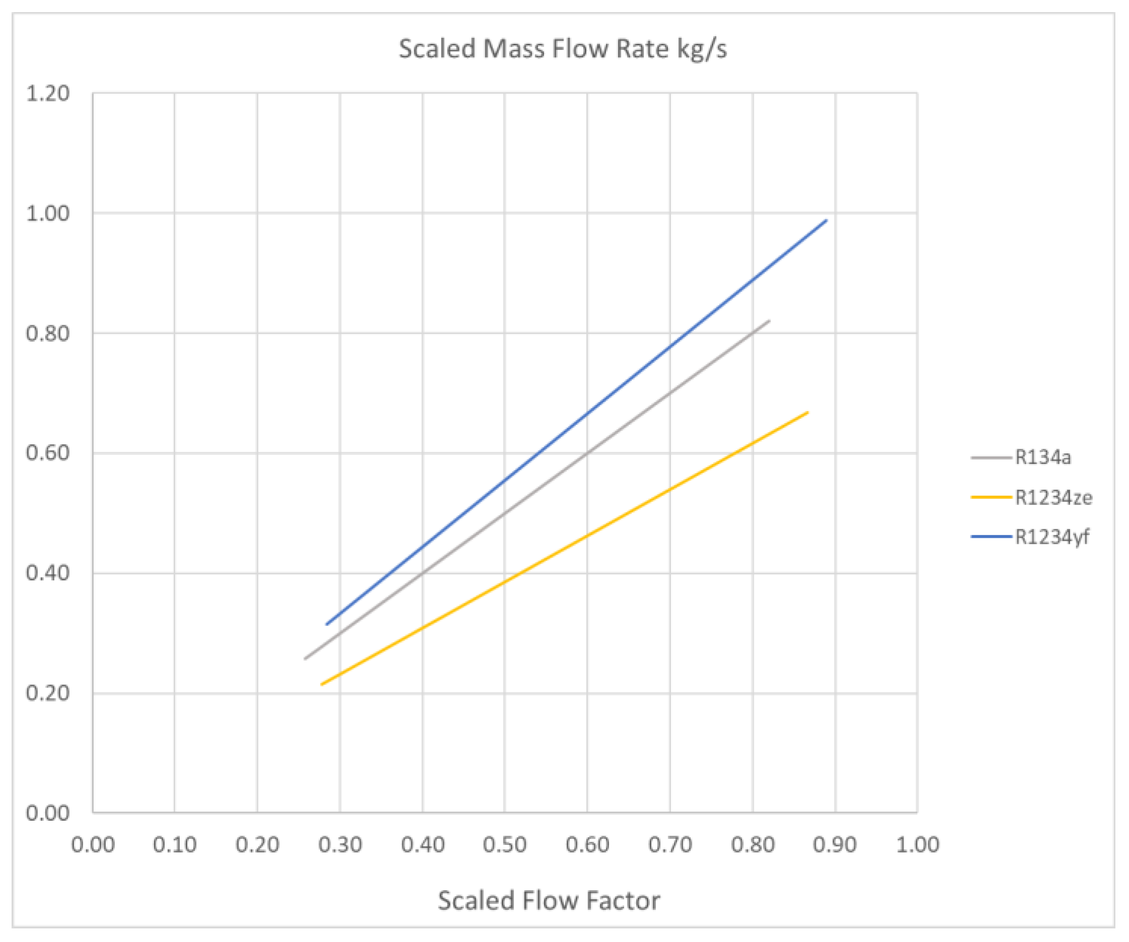
For the specific power consumption, it is highly dependent on the pressure ratio that can be implied by Equation (6) indicating that the higher pressure ratio generally requires higher power to achieve. Thus, the specific power consumption shows the similar trend as the pressure ratio plot that R1234yf has the highest power consumption, followed by R1234ze. At the same flow factor, R1234yf has the highest corresponding mass flow rate, followed by R134a with a slightly lower mass flow rate, while R1234ze has a significantly lower mass flow rate than R1234yf and R134a. When the specific power is multiplied by the mass flow rate to obtain the compressor power consumption, R1234yf will take the highest power consumption, but R134a will take the second highest power consumption, and R1234ze will take the least power.
Figure 22 illustrates the scaled mass flow rate vs. the scaled SDT across various speed lines. Due to the changes in fluid properties, there is a significant variation in the maximum mass flow rate through the compressor at the same speed. Theoretically, the compressor should display a similar maximum flow factor at identical corrected speeds. Because of the higher density of R1234yf and R134a under suction conditions, the compressor processes a greater mass flow with these refrigerants than with R1234ze, given the same maximum flow factor. Furthermore, the maximum flow factor increases as the corrected speeds rise, as depicted in Figure 15. These combined effects result in R1234yf achieving the highest mass flow rate (dot mark with the same color as the corresponding refrigerant color), followed by R134a, with R1234ze exhibiting the lowest at a speed of 1.08 ND.
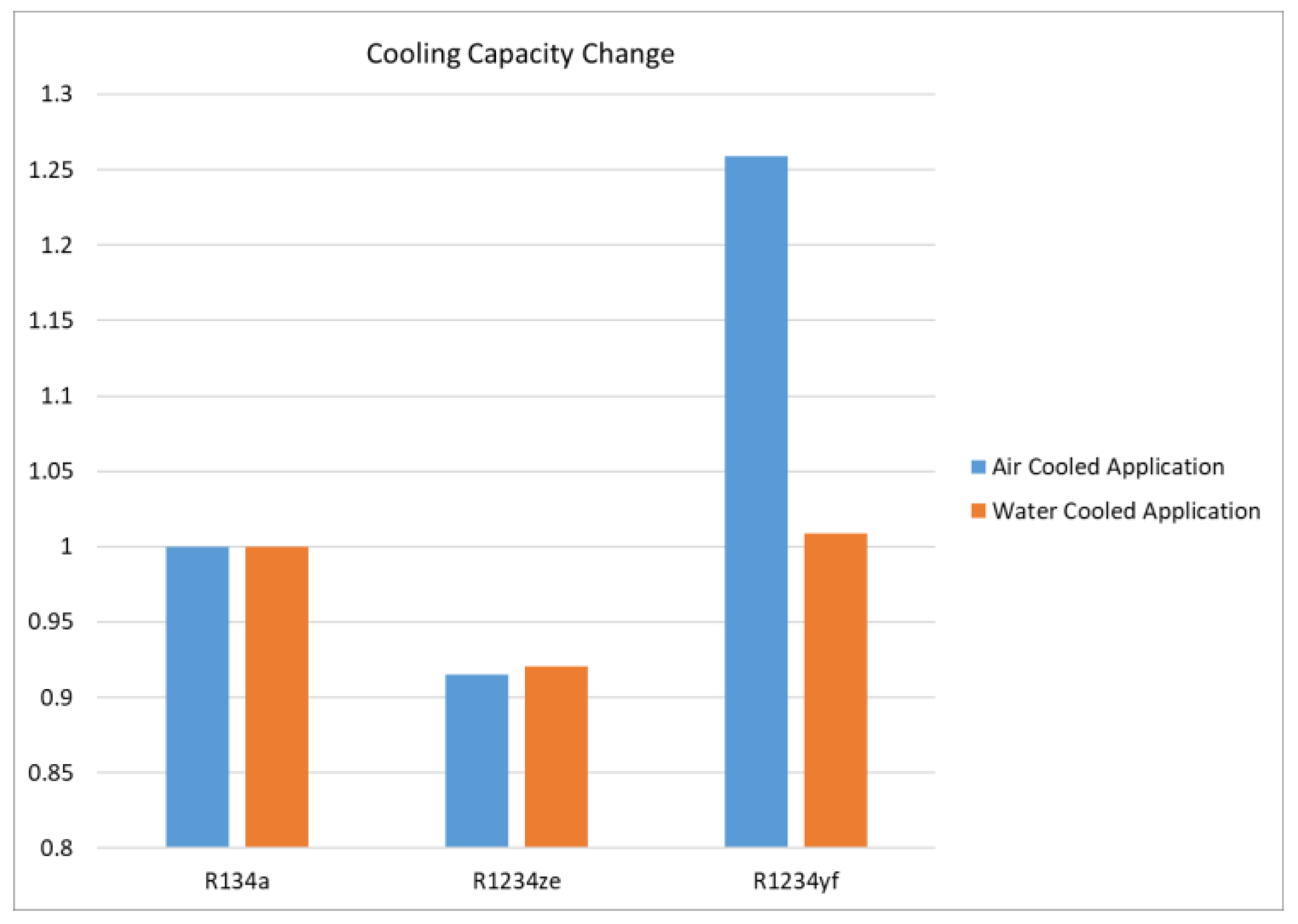
These changes in mass flow, coupled with differences in specific latent heat capacities, also impact the compressor’s cooling capacity. Figure 23 highlights the changes in cooling capacity for R1234ze and R1234yf with R134a as the baseline in both air-cooled and water-cooled chiller conditions at the full load SDT specified by AHRI standards. The max mass flow rates for each refrigerant are marked as bullets in Figure 22. At 1.08 ND, R1234ze shows a reduced cooling capacity in both air- and water-cooled scenarios. R1234yf demonstrates an increased capacity compared to R134a, particularly in air-cooled applications. Considering compressor power consumption, R1234ze’s cooling capacity can be enhanced by operating at higher speeds, while R1234yf may fail to reach its maximum capacity if the compressor drive is unable to supply the necessary power at the max mass flow rates.

5. Conclusions

The performance change in a refrigerant centrifugal compressor when switching from R134a to R1234ze and R1234yf is studied using a novel method that combines CFD simulations with the 1D meanline code. The findings indicate the following:
  • Pressure ratio changes: R1234yf and R1234ze achieve higher pressure ratios than R134a at the same speed due to the lower inlet speed of sound, which leads to a higher corrected speed. Specifically, the maximum pressure ratio increased by 29% for R1234yf and 16% for R1234ze compared to R134a.
  • Efficiency changes: R1234ze exhibits a maximum of 2% higher efficiency than R1234yf and R134a, caused by a combination of the factors including the Reynolds number, isentropic exponents, and the specific compressor geometry.
  • Power consumption change: R1234yf requires significantly more power to operate at the same speed compared to R134a, which can be a limiting factor for its use as a drop-in replacement. This study observed a maximum power increase of 36% when switching from R134a to R1234yf, whereas R1234ze demonstrated a 16% reduction in maximum power consumption.
  • Capacity changes: In water-cooled applications, R1234yf has a maximum capacity close to R134a, while R1234ze experiences an 8% reduction. In air-cooled applications, R1234yf shows a significant increase in maximum capacity due to the higher corrected speed, while R1234ze is limited by the maximum compressor speed and reaches a 9% lower maximum capacity comparing to R134a.
The significant thermodynamic property changes among the three refrigerants also indicate that the performance of other components in the chiller system will be impacted. Thus, all these changes should be comprehensively considered when using the low-GWP refrigerants as a drop-in for R134a to ensure the chiller system can still deliver the required cooling target efficiently and effectively.

Author Contributions

Conceptualization, Y.W. and J.Y.; data curation, Y.W.; formal analysis, Y.W.; investigation, Y.W.; methodology, Y.W. and J.Y.; project administration, J.Y.; resources, J.Y.; software, J.Y.; supervision, J.Y.; validation, Y.W.; visualization, Y.W.; writing—original draft, Y.W.; writing—review and editing, Y.W. and J.Y. All authors have read and agreed to the published version of the manuscript.

Funding

This research received no external funding.

Data Availability Statement

The data that has been used is confidential.

Acknowledgments

The authors would like to thank Danfoss Turbocor for allowing the publication of this work.

Conflicts of Interest

The authors are employees of Danfoss.

Nomenclature

ηefficiency (-)
πpressure ratio (-)
µdynamic viscosity (Pa·s−1)
γisentropic exponent (J·kg−1·K−1)
aspeed of sound (m·s−1)
hspecific enthalpy (J·kg−1)
dimpeller diameter (m)
FFflow factor (m−2)
IGVinlet guide vane (-)
Nrotating speed (rad·s−1)
Nccorrected rotating speed (rad·m−1)
NDdesigned rotating speed (rad·s−1)
m ˙ mass flow rate (kg·s−1)
sspecific entropy (J·kg−1·K−1)
SSTsaturated suction temperature (°C)
SDTsaturated discharge temperature (°C)
SSHsuction superheat temperature (°C)
VFDvariable frequency drive (-)
COPcoefficient of performance (-)
CFDcomputational fluid dynamics (-)
Subscripts
1condition at inlet
01total condition at inlet
2condition at discharge
02total condition at discharge
sisentropic
Pevaluated at constant pressure
Vevaluated at constant volume

References

  1. Copernicus. Record Warm November Consolidates 2023 as the Warmest Year. 2023. Available online: https://climate.copernicus.eu/record-warm-november-consolidates-2023-warmest-year (accessed on 10 January 2024).
  2. World Meteorological Organization. 2023—A Historic Climatic Year, as WMO Secretary-General Taalas Successfully Completes His Mandate. 2023. Available online: https://wmo.int/news/media-centre/2023-historic-climatic-year-wmo-secretary-general-taalas-successfully-completes-his-mandate#:~:text=According%20to%20WMO’s%20provisional%20State,the%20warmest%20November%20on%20record (accessed on 4 February 2024).
  3. Roberts, M.W. Finishing the job: The Montreal Protocol moves to phase down hydrofluorocarbons. Rev. Eur. Comp. Int. Environ. Law 2017, 26, 220–230. [Google Scholar] [CrossRef]
  4. Gopalnarayanan, S. Choosing the right refrigerant. Mech. Eng. 1998, 120, 92–95. [Google Scholar] [CrossRef]
  5. Fedele, L.; Lombardo, G.; Greselin, I.; Menegazzo, D.; Bobbo, S. Thermophysical Properties of Low GWP Refrigerants: An Update. Int. J. Thermophys. 2023, 44, 80. [Google Scholar] [CrossRef]
  6. Drofenik, J.; Urbancl, D.; Goričanec, D. Comparison of the New Refrigerant R1336mzz (E) with R1234ze (E) as an Alternative to R134a for Use in Heat Pumps. Processes 2022, 10, 218. [Google Scholar] [CrossRef]
  7. Giuffre, A.; Colonna, P.; Pini, M. The effect of size and working fluid on the multi-objective design of high-speed centrifugal compressors. Int. J. Refrig. 2022, 143, 43–56. [Google Scholar] [CrossRef]
  8. Van den Braembussche, R. Design and Analysis of Centrifugal Compressors; John Wiley & Sons: Hoboken, NJ, USA, 2019. [Google Scholar]
  9. Lüdtke, K.H. Process Centrifugal Compressors: Basics, Function, Operation, Design, Application; Springer Science & Business Media: Berlin/Heidelberg, Germany, 2013. [Google Scholar]
  10. Li, G. Evaluation of Multistage Centrifugal Chiller Performance Metrics with Different Low Global Warming Potential Refrigerants. J. Eng. Thermophys. 2022, 31, 340–374. [Google Scholar] [CrossRef]
  11. Hsu, C.N.; Wang, S.H. Evaluating the performance of water chillers equipped with constant-or variable-frequency centrifugal compressors. Processes 2021, 9, 1039. [Google Scholar] [CrossRef]
  12. Yang, Z.; Feng, B.; Ma, H.; Zhang, L.; Duan, C.; Liu, B.; Zhang, Y.; Chen, S.; Yang, Z. Analysis of lower GWP and flammable alternative refrigerants. Int. J. Refrig. 2021, 126, 12–22. [Google Scholar] [CrossRef]
  13. Sethi, A.; Becerra, E.V.; Motta, S.Y. Low GWP R134a replacements for small refrigeration (plug-in) applications. Int. J. Refrig. 2016, 66, 64–72. [Google Scholar] [CrossRef]
  14. Colombo, L.P.M.; Lucchini, A.; Molinaroli, L. Experimental analysis of the use of R1234yf and R1234ze (E) as drop-in alternatives of R134a in a water-to-water heat pump. Int. J. Refrig. 2020, 115, 18–27. [Google Scholar] [CrossRef]
  15. Li, Z.; Liang, K.; Jiang, H. Experimental study of R1234yf as a drop-in replacement for R134a in an oil-free refrigeration system. Appl. Therm. Eng. 2019, 153, 646–654. [Google Scholar] [CrossRef]
  16. Yataganbaba, A.; Kilicarslan, A.; Kurtbaş, İ. Exergy analysis of R1234yf and R1234ze as R134a replacements in a two evaporator vapour compression refrigeration system. Int. J. Refrig. 2015, 60, 26–37. [Google Scholar] [CrossRef]
  17. Aized, T.; Rashid, M.; Riaz, F.; Hamza, A.; Nabi, H.Z.; Sultan, M.; Ashraf, W.M.; Krzywanski, J. Energy and exergy analysis of vapor compression refrigeration system with low-Gwp refrigerants. Energies 2022, 15, 7246. [Google Scholar] [CrossRef]
  18. Aized, T.; Hamza, A. Thermodynamic analysis of various refrigerants for automotive air conditioning system. Arab. J. Sci. Eng. 2019, 44, 1697–1707. [Google Scholar] [CrossRef]
  19. Li, G. Performance evaluation of low global warming potential working fluids as R134a alternatives for two-stage centrifugal chiller applications. Korean J. Chem. Eng. 2021, 38, 1438–1451. [Google Scholar] [CrossRef]
  20. Park, J.H.; Shin, Y.; Chung, J.T. Performance prediction of centrifugal compressor for drop-in testing using low global warming potential alternative refrigerants and performance test codes. Energies 2017, 10, 2043. [Google Scholar] [CrossRef]
  21. Yi, K.; Zhao, Y.; Liu, G.; Yang, Q.; Yu, G.; Li, L. Performance evaluation of centrifugal refrigeration compressor using R1234yf and R1234ze (E) as drop-in replacements for R134a refrigerant. Energies 2022, 15, 2552. [Google Scholar] [CrossRef]
  22. NIST. Reference Fluid Thermodynamic and Transport Properties Database (REFPROP). 2019. Available online: https://www.nist.gov/image/refroppng (accessed on 29 May 2024).
  23. Casey, M. The effects of Reynolds number on the efficiency of centrifugal compressor stages. J. Eng. Gas Turbines Power 1985, 107, 541–548. [Google Scholar] [CrossRef]
  24. Valdés, M.; Sebastián, A.; Abbas, R. Reynolds-number-dependent efficiency characterization of a micro-scale centrifugal compressor using non-conventional working fluids. Energy Convers. Manag. 2018, 177, 224–232. [Google Scholar] [CrossRef]
  25. Urcia, J.; Yan, J.; Fagundes, T. Economizer Location Optimization for a Centrifugal Compressor with Refrigerant as Working Fluid. In Turbo Expo: Power for Land, Sea, and Air; American Society of Mechanical Engineers: New York, NY, USA, 2022. [Google Scholar]
  26. Ronald, H. Centrifugal Compressors: A Strategy for Aerodynamic Design and Analysis; American Society of Mechanical Engineers Press: New York, NY, USA, 2000. [Google Scholar]
  27. Casey, M.; Robinson, C. A unified correction method for Reynolds number, size, and roughness effects on the performance of compressors. Proc. Inst. Mech. Eng. Part A J. Power Energy 2011, 225, 864–876. [Google Scholar] [CrossRef]
  28. Casey, M.; Robinson, C. A method to estimate the performance map of a centrifugal compressor stage. J. Turbomach. 2013, 135, 021034. [Google Scholar] [CrossRef]
  29. TurboTides. Available online: https://spinpous.com/ (accessed on 29 May 2024).
  30. Strub, R.A.; Bonciani, L.; Borer, C.J.; Casey, M.V.; Cole, S.L.; Cook, B.B.; Kotzur, J.; Simon, H.; Strite, M.A. Influence of the Reynolds number on the performance of centrifugal compressors. J. Turbomach. 1987, 109, 541–544. [Google Scholar] [CrossRef]
  31. Tiainen, J.; Jaatinen-Värri, A.; Grönman, A.; Backman, J. Numerical study of the Reynolds number effect on the centrifugal compressor performance and losses. In Turbo Expo: Power for Land, Sea, and Air; American Society of Mechanical Engineers: New York, NY, USA, 2016. [Google Scholar]
  32. Wiesner, F. A new appraisal of Reynolds number effects on centrifugal compressor performance. J. Eng. Power. 1979, 101, 384–392. [Google Scholar] [CrossRef]
  33. Hoffmann, H.; Stuhldreier, L.; van Rennings, R.; Jeschke, P. Influence of different gases on the Design Point of an Industrial Axial Compressor and deduced aerodynamical Rematching Methodology. J. Glob. Power Propuls. Soc. 2020, 4, 238–252. [Google Scholar] [CrossRef]
  34. Cravero, C.; Marsano, D.; Sishtla, V.; Halbe, C.; Cousins, W.T. Numerical investigations of near surge operating conditions in a two-stage radial compressor with refrigerant gas. J. Eng. Gas Turbines Power 2024, 146, 021010. [Google Scholar] [CrossRef]
  35. Zhu, W.; Ren, X.D.; Li, X.S.; Gu, C.W. Analysis and improvement of a two-stage centrifugal compressor used in an MW-level gas turbine. Appl. Sci. 2018, 8, 1347. [Google Scholar] [CrossRef]
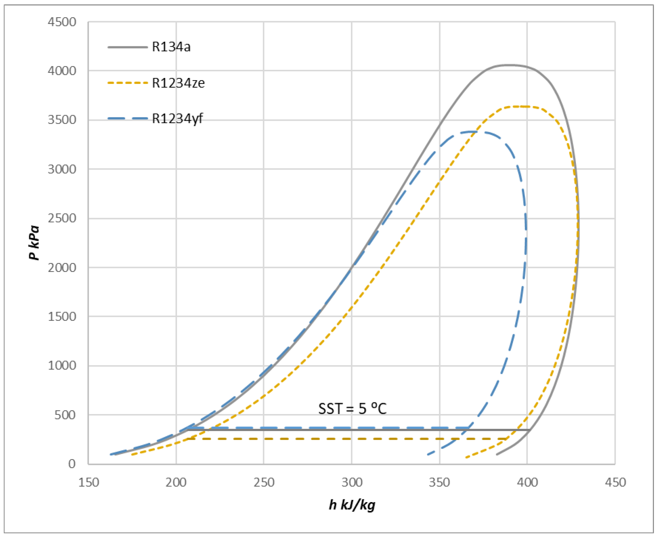
Figure 1. Pressure—enthalpy diagram of R134a, R1234ze, and R1234yf.
Energies 17 02784 g001
Figure 2. Temperature—enthalpy diagram of R134a, R1234ze, and R1234yf.
Energies 17 02784 g002
Figure 3. Volumetric heat capacity ratio.
Energies 17 02784 g003
Figure 4. Speed of sound at different saturated gas conditions.
Energies 17 02784 g004
Figure 5. Enthalpy—entropy change in a compression process.
Energies 17 02784 g005
Figure 6. Stage 1 impeller (left) and Stage 2 impeller (right).
Energies 17 02784 g006
Figure 7. Assembly of compressor main components.
Energies 17 02784 g007
Figure 8. The test rig schematic (A) and CFD simulation flow domains (B). The black lines represent the refrigerant loop; the blue lines represent the water loop that removes the heat from the refrigerant loop.
Energies 17 02784 g008
Figure 9. First stage impeller meshing.
Energies 17 02784 g009
Figure 10. Comparison of compressor pressure ratio for R1234ze—test vs. CFD.
Energies 17 02784 g010
Figure 11. Comparison of compressor efficiency for R1234ze—test vs. CFD.
Energies 17 02784 g011
Figure 12. Compressor pressure ratio—CFD vs. 1D at selected speeds.
Energies 17 02784 g012
Figure 13. Compressor efficiency—CFD vs. 1D at selected speeds.
Energies 17 02784 g013
Figure 14. Compressor pressure ratio from 1D prediction.
Energies 17 02784 g014
Figure 15. Actual speed vs. corrected speed.
Energies 17 02784 g015
Figure 16. Compressor saturated discharge temperature changes.
Energies 17 02784 g016
Figure 17. Compressor isentropic efficiency.
Energies 17 02784 g017
Figure 18. Reynolds number at studied speeds.
Energies 17 02784 g018
Figure 19. Compressor power consumption from 1D prediction.
Energies 17 02784 g019
Figure 20. Specific work at studied speed.
Energies 17 02784 g020
Figure 21. Mass flow rate vs. flow factor.
Energies 17 02784 g021
Figure 22. Full-load mass flow changes in switching refrigerant.
Energies 17 02784 g022
Figure 23. Cooling capacity change.
Energies 17 02784 g023
Disclaimer/Publisher’s Note: The statements, opinions and data contained in all publications are solely those of the individual author(s) and contributor(s) and not of MDPI and/or the editor(s). MDPI and/or the editor(s) disclaim responsibility for any injury to people or property resulting from any ideas, methods, instructions or products referred to in the content.