1. Introduction
Electricity markets globally are undergoing a rapid structural transition as a result of the decarbonisation of the energy generating infrastructure, which, by nature of the new technologies, is inherently decentralised. For distribution networks, this is disrupting the existing paradigm of how the grid was managed and introducing new operational problems which were not considered when the distribution network was designed. In the Australian national electricity market (NEM), there is presently significant activity focused on strategies for DER integration, with numerous projects underway, stakeholder consultations and working groups established by government agencies including the Energy Security Board (ESB) [
1], the Australian Renewable Energy Agency (ARENA) through its Distributed Energy Integration Program (DEIP) [
2], and the Energy Networks Association [
3]. Several DER-related projects have now reported back their findings and are moving to an implementation stage, including Common Smart Inverter Profile Australia (CSIP-Aus) [
4], Dynamic Operating Envelopes (DOEs) [
2], and electric vehicle (EV) charging. DNSP trials of DOEs, distribution energy resource management systems (DERMS), and advanced voltage management strategies are well progressed in several jurisdictions. The current Australian National DER standards framework is based around the Australian Standard AS/NZS 4777.2:2020 [
5] for the grid connection of energy systems via inverters. At the basic level, this standard currently governs the behaviour and safety of the power electronic converter systems which couple customer energy resources to the grid. Because the governance of inverter standards for DER is in transition, certification and compliance regimes for the new interoperability features of DER equipment are still being developed by the respective working groups. A recent rule change has now inserted compliance with AS/NZS 4777.2 [
5] into the National Electricity Rules (NER) as a mandatory requirement for all DER inverters in the NEM, regardless of the jurisdiction. As is happening elsewhere, Australian jurisdictions are progressing a standard inverter communication framework, known here as the Common Smart Inverter Profile Australia (CSIP-Aus) which is based on IEEE 2030.5 [
6]; though not yet mandatory in the inverter standard, it will enable dynamic export limits for DERs, also known as flexible connections. Similarly, the DER inverter standard IEEE 1547.1-2020 [
7] in the U.S. now includes mandatory communication interfaces: SunSpec Modbus, IEEE 1815 (DNP3), or IEEE 2030.5 [
8]. Inverter parameters need to be adjustable remotely through these interfaces, and this process is part of the certification and testing regime. This has been challenging for vendors while frustrating for DNSPs and highlights the importance of
interoperability for DER control by DNSPs.
During recent years, several overall trends in the theory and practice of DER control have been identified, which can be understood in the broader context of electricity market restructuring, decentralisation, and rapid advancements in power electronics and the automation of large-scale cyber–physical systems. These trends are as follows:
Small-scale DERs are now expected to actively participate in the frequency and voltage regulation of power networks. This was not previously the case where, during a disturbance in the grid, small-scale DERs were simply disconnected.
DER communication protocols are transitioning away from serial data exchange using register-based messaging towards sematic-based, hierarchical data models and switched-packet networks, an example being the use of the Common Information Model (CIM) and IP-based protocols.
There is a convergence of operation and planning in distribution network service providers (DNSPs) and a separation of the control layer from the hardware or data processing layer in networked control systems. An example of this is network functions virtualisation (NFV).
The wide-scale sensing and measurement of electrical networks is enabling DER control, which is data-driven, and active network management, which is decentralised.
The concept of interoperability is becoming fundamental for DER control structures to be realised in a practical sense and is the focus of some significant policy and research efforts. Importantly, the concept is not simply related to the compatibility of hardware from different vendors; it is more far reaching and relates to the multi-criteria optimisation of any large-scale interconnected system using distributed message passing and the alignment between local and global objectives in a control-theoretic sense [
9]. In this regard, it is important to establish a theoretical framework for DER control with clearly defined concepts. As a simple example illustrates, if network voltage support uses an autonomous multi-agent-based solution, how should a group of DERs broker an agreement as to the level of power curtailment from each device and execute the control actions required? This is an open and complex question. Therefore, as a theoretical background and reference for the ideas presented in later sections, the paper includes a primer on control theory for large-scale interconnected systems.
Australian distribution networks are either regulated privately owned businesses or corporatised government entities that are registered to participate in the National Electricity Market as distribution network service providers (DNSPs).
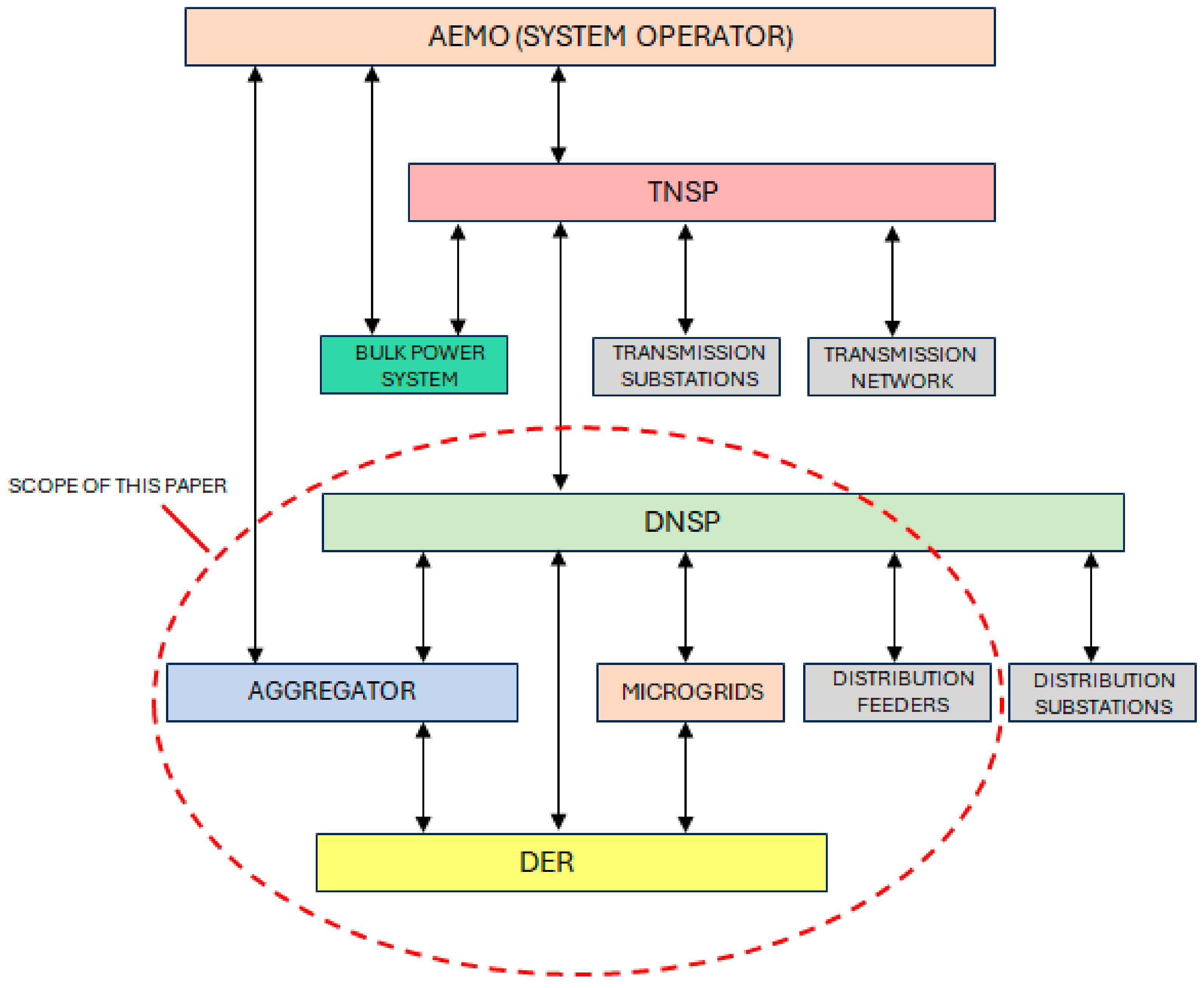
Figure 1 shows the organisational structure of the Australian electrical power grid according to provider roles. DNSPs are responsible for operating the low-voltage (LV) and medium-voltage (MV) network, while transmission network service providers (TNSPs) operate the high-voltage (HV) network. Normally, small-to-medium scale DERs (less than 5MW) cannot participate directly in the electricity market but will utilise traders also known as aggregators who are licensed to trade energy and network services on their behalf. As part of this agreement, DER owners will relinquish control of their assets to an aggregator who will coordinate the dispatch of a group of contracted DER units. For other DER assets such as commercial and industrial (C&I) customers, the DNSPs can control the DERs directly through their SCADA network. The scope of the paper is shown in
Figure 1. The market operator (AEMO) is currently running DER market integration trials that allow for the direct participation of DERs in the wholesale electricity market. Previous review papers on the topic of DER integration in the grid have focused on particular aspects of the smart grid that include DERs and microgrids [
10], communication and information technology (IT) [
11,
12], or multi-agent systems [
13,
14] or have been focused on the bulk power system and energy markets [
15], including the provision of ancillary services [
16], and transmission networks [
17]. A comprehensive review of DER control as a tool for active network management for distribution network operators has not been provided among these works. While other research has focused on novel proposals for DER control structures that improve particular performance measures [
18], a comprehensive review of DNSP control and management strategies of DERs by DNSPs has not been provided.
The space for DER control solutions in the marketplace is wide and encompasses behind-the-meter electronics through to enterprise-scale software platforms and all the enabling technologies related to automation, data acquisition, and communication. The usefulness of enterprise DERMS for specific DER control use cases is an important topic in the Australian context; these are, after all, expensive systems to implement, and there are practical engineering considerations that need to be understood by distributors. Active network management (ANM) is not currently utilised for most LV networks, and the operating philosophy of control rooms may differ widely depending on the regional geography, legacy systems and assets, and size of the distribution network area [
19,
20]. Rural networks frequently have no reliable telemetry outside of the population centres. DER control is an engineered bespoke solution for each DNSP which depends on the size of the customer cohort, e.g., residential up to 10 kW and industrial and commercial greater than 100 kW. The technological landscape is rapidly evolving as are the compliance frameworks, and the report provides an overview of current research areas and possible future directions. Indeed, it can be seen that there is a critical interdependency between information and energy technologies which highlights that nature of the smart grid as a cyber–physical system. DNSPs will need to adopt flexible strategies to accommodate continuously evolving consumer products and behaviour.
The structure of the paper is as follows:
Section 2 defines the terminology and introduces the concepts and architectures which are used throughout the paper. In this section, we develop a conceptual model of DER control by distribution networks, which can be seen as the application of a generalised control problem from large-scale interconnected systems theory. The conceptual tools of classical control theory are useful as a conceptual model to illustrate the operating principles of DER control strategies for distribution networks.
Section 3 discusses the topic of active network management (ANM) for distribution networks which is now the dominant paradigm for the management of distribution networks. This section addresses the practical questions of how existing distribution management systems (DMSs) can be extended and enhanced to facilitate DER control, which naturally leads to the topic of distributed energy resource management systems (DERMSs). This is discussed in the context of Australian DNSPs and several emerging challenges facing the industry. As an example, to illustrate several important design considerations for a DERMS, the application case of voltage regulation along a PV-rich feeder is used to illustrate several challenges for DER control on distribution networks.
Section 4 addresses the progress of technical standards for DER control and particularly the important issue of interoperability, which is discussed in detail. An overview of the different DER communication protocols is provided, with a focus on IEEE 2030.5 which has become the de facto protocol is several regions, including Australia. The topic of DER control is fundamentally related to the control of power conversion systems, since it is normally the power electronic inverter which is controlling the power flows from an energy source to the grid. In this regard,
Section 5 provides an overview of the recent trends in control architectures for grid-tied inverters used in DER applications.
Section 6 outlines several active research areas related to DER control within universities, government, and private research institutes. The paper highlights several key areas of innovation which will impact the future direction of DER control methods. A particular example of one area of innovation is around wireless communication systems, specifically next-generation cellular, IOT wireless, and satellite communication systems, which will enable DER control for rural networks and a range of other applications. Cybersecurity is an important consideration for DNSPs, and a concise summary of the most relevant issues for DER control is provided. In conclusion,
Section 7 provides a summary of the existing problems and challenges for DER control by DNSPs and open issues which still need to be resolved.
2. Preliminaries: Definitions, Concepts, and Architectures
The discussion topic of DER control within the utility sector frequently uses terms and concepts where the meaning may be intuitively understood, though no rigorous definition is provided in a control-theoretic sense. As the paper intends to present a comprehensive technical overview of the topic, it is important that these foundational concepts are included at the start and can be considered the preliminaries for the article. This section establishes the conceptual frameworks for DER control, based on rigorous engineering definitions, and a comprehensive review of the latest research in automation and control theory as applied to the operation of modern electricity grids. The following concepts are introduced in this section: control architectures including centralised, decentralised, distributed, and multi-agent systems and DERMS concepts that can include orchestration, aggregation, clustering, and virtualisation. The section also includes a brief description of graph theory and large-scale decomposition theory.
The topic of distributed control in electric power systems is large and beyond the scope of this report. Instead, a brief overview of three popular frameworks currently being considered for grid automation is provided. Specifically,
multi-agent systems, which are the focus of IEEE Power Engineering Society’s Multi-Agent Systems (MASs) Working Group [
21,
22],
laminar architectures, which are favoured by the EPRI and the U.S. DoE [
9], and what has been termed the
web-of-cells approach [
23,
24]. With respect to control system architectures, we adopt the following control-theoretic definitions [
25,
26]:
Decentralised control implies autonomous local control;
Distributed control implies a group of nodes or agents which exchange information across an interconnected graph, for example, a peer-to-peer network;
Centralised control has a single master controller, or control centre (CC), with a one-to-many radial network architecture.
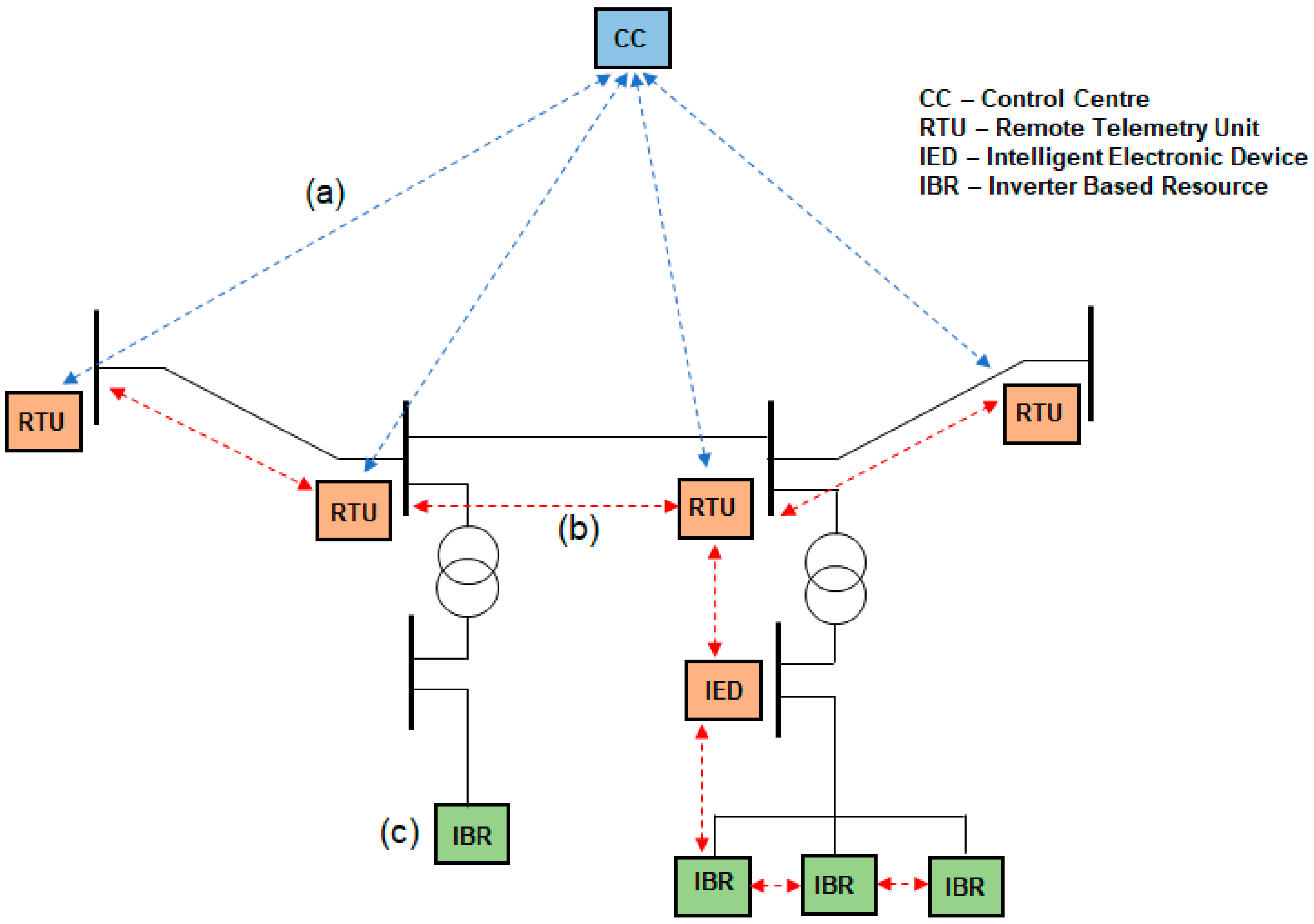
The distinction between control architectures is best illustrated with a single-line diagram (refer to
Figure 2 below). The diagram shows an idealised segment of the distribution network and includes two substations, remote telemetry units (RTUs) and inverter-based resources (IBRs), which are coupled to the low-voltage network, and a central control centre (CC) where the DNSP’s SCADA is hosted. In this figure, (a) represents the centralised control signals and (b) represents the distributed control signals, while (c) is decentralised or local control. It can be observed that the distributed control signals have a graph structure which in some sense corresponds to the electrical network, and this idea is formalised in a later section.
Naturally, some redundancy or duplication may also be present, though the fundamental architecture does not change. Importantly, in distributed control, there is normally, though not necessarily, a functional decomposition of an overall system control problem and the allocation of sub-problems or tasks to each node. Conceptually, the control algorithm is vertically distributed, while the physical nodes are horizontally distributed. Information exchange between nodes is normally bi-directional by explicit messaging across data links, for example, optical fibre or cellular wireless, not to discount the possibility of implicit messaging by other forms of signalling across a network, for example, using frequency or voltage. The salient point is that in distributed control, the nodes may exhibit cooperative action, with coordinated behaviour for a global purpose.
A control system architecture is scalable if it easily accommodates growth in connected elements, while it is extensible if it easily accommodates new functionality. Aggregation involves the summation of power/energy of multiple DERs, e.g., for market participation, while orchestration involves the coordination of a group or cluster of DERs to achieve operational objectives, e.g., Volt–Var Optimisation (VVO).
2.1. Conventional Control Hierarchy for Electric Power Systems
Due to the wide range of dynamic response times of power system internal states and measured outputs, the regulation of different power system outputs occurs across increasing time scales; therefore, it is natural to consider the concept of a structured hierarchy of control actions in the control system design architecture. Importantly, this concept should be considered independently from notions of centralised or distributed control, since a control hierarchy can be implemented using either architecture. Multi-generator electrical power networks, particularly on a large scale, are complex, nonlinear, dynamic systems where control is based on a hierarchical strategy of temporal and spatial decompositions, using engineering experience, robust design concepts, and well-understood features such as the diagonal dominance of the system matrices [
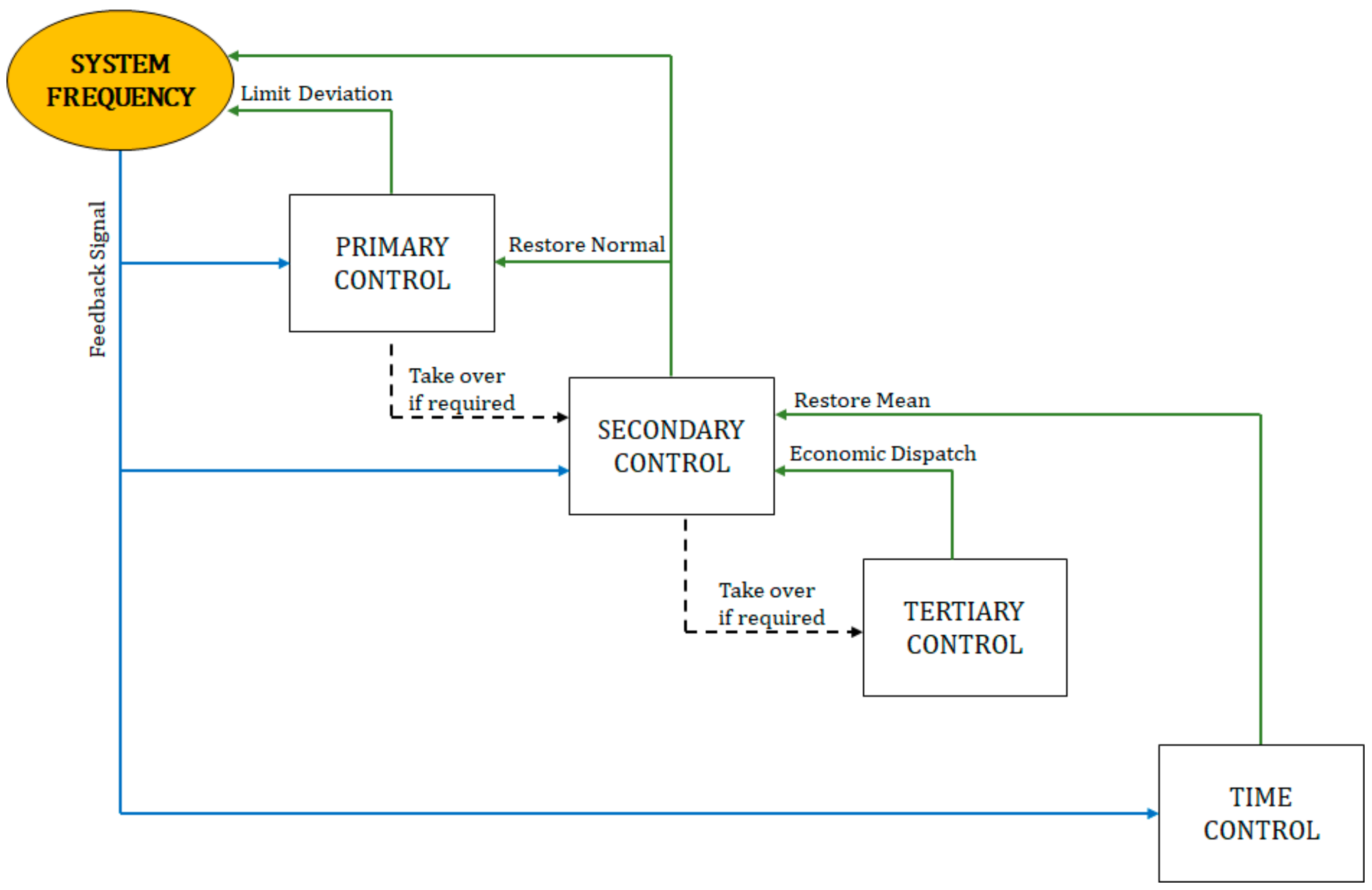
27]. This is consistent with a single-grid ownership structure based on centralised command and supervisory control, with fixed performance objectives and metrics. Primary control is the action of the fast inner loops, which regulate the output. The purpose of secondary control is to eliminate offsets or drift in a small subset of state variables (or outputs) to desirable rms or magnitude norms and is normally characterised by integral control action, while tertiary control is responsible for ensuring that generation is dispatched to meet aggregate demand over a longer timeframe, normally using constrained least-cost convex solver algorithms. An example of a control hierarchy is shown in
Figure 3.
Power electronic converter controls and architecture have advanced significantly in recent years. Grid-interfaced power electronic converters are now pervasive within the electricity network. Grid-connected renewable energy converters are predominantly grid-following by design, with no capability, until more recently, for autonomous operation or some level of grid support function. Increasing the deployment of energy storage converters implementing the primary control of voltage, frequency, and power-sharing capability enables the autonomous operation of microgrids in a practical sense [
29].
The conventional hierarchical power system model is currently being disrupted as electrical power systems transition to an open-access regime, along with the rapid progress of enabling technologies such as embedded intelligent sensing, high-speed wireless communication, and highly controllable power electronic interfaces. Controller designs will need to consider distributed multi-layered performance objectives and dynamic topologies with the aim of the
just-in-time and
just-in-place delivery of services [
27]. Under this scenario, the distinction between what is a primary, secondary, or tertiary control action is no longer relevant. In this regard, new energy paradigms are being considered, and new automation frameworks are being developed.
2.2. Control of Distributed Generation on Graphs
Taking inspiration from the self-organising behaviour observed in certain natural systems, this approach enables the tools of graph theory and information flow to be applied to DER control problems. The concept is particularly useful for understanding distributed architectures using agent-based control. The advantage of such an approach is that, considering the electricity grid as a dynamic cyber–physical system, the flow of power or information is indistinguishable in a strictly graph-theoretic sense. Graph-theoretic methods can be traced back to the study of nonlinear behaviour in coupled electrical circuits and systems based on their structural properties [
30,
31]. The future power grid will be a cyber–physical system characterised by both physical and information couplings between agents. As a theoretical framework for power system control, this has received increasing focus in the research literature [
32,
33]. Referring to
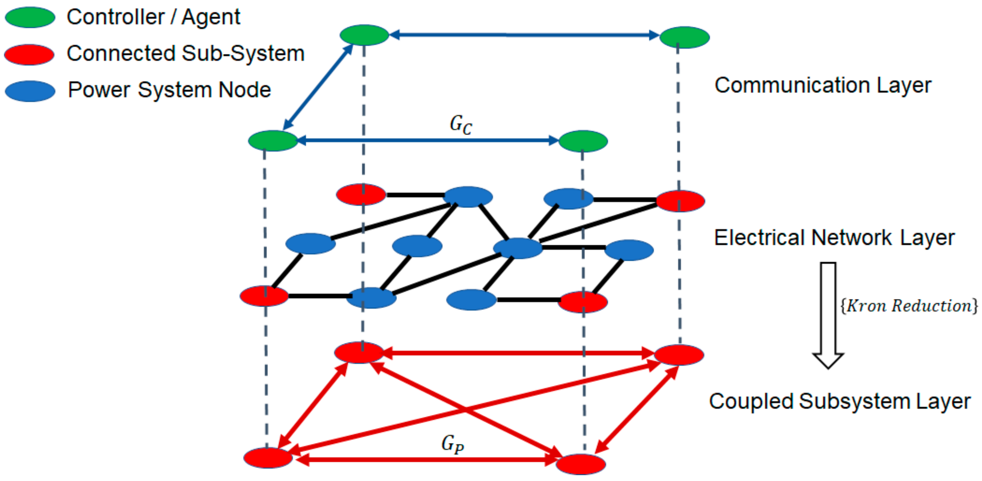
Figure 4, the electrical network has an associated physical graph,
, which represents the connectivity structure of the Kron-reduced electrical sub-system layer, and an associated communication graph,
, that represents the communication layer. The topic of this report is to describe the range of control strategies over
, which are useful for DER control problems.
2.3. Decomposition and Coordination Algorithms
Due to the rapid advancement of communications technology and distributed computing, distributed control has become an active research area, with work relating to team problems and the control of large-scale multi-variable and multi-level systems originating from, amongst others, [
34,
35]. Decomposition–coordination algorithms utilise sequential messages passing between elements in the network to calculate solutions to optimisation problems, or rather, optimal control problems since this is the topic of interest. The elements are normally decentralised in a geospatial sense. The rationale is that it is easier, from a computational perspective, to break down a large central control problem into smaller, independent sub-problems. The theoretical foundations of these mathematical techniques were developed to solve constrained optimisation problems for large-scale dynamics systems. Decomposition and coordination concepts using dynamic programming involving multiple agents were first introduced in [
36] and further developed by, for example, [
37,
38]. In the power system control domain, these techniques have enabled the distributed model predictive control (D-MPC) of frequency as in [
39,
40], the use of alternating direction method of multipliers (ADMMs) for reactive power control [
41], and proximal atomic coordination (PAC) for the voltage regulation of distribution networks [
42].
The decomposition of a large-scale system into coupled sub-systems, each with a controller agent, is shown in
Figure 4 which represents a cyber–physical network. Physical coupling may, for example, be an electrical network, with information flows over a wireless network. Each sub-system produces a desired output and receives an input signal from its controlling agent, to which it sends state information for processing. Importantly, both physical and information couplings have a graph-theoretic interpretation, which provides deeper insights into the collective behaviour of the system and forms the theoretical basis for multi-agent theory and cooperative control. Decomposition and coordination algorithms have application in the constrained least-cost dispatch of microgrids, energy routing problems, scheduling problems, and cross-layer optimisation [
43]. For linear quadratic regulator synthesis using distributed algorithms, the reader is referred to [
44,
45].
As can be observed in
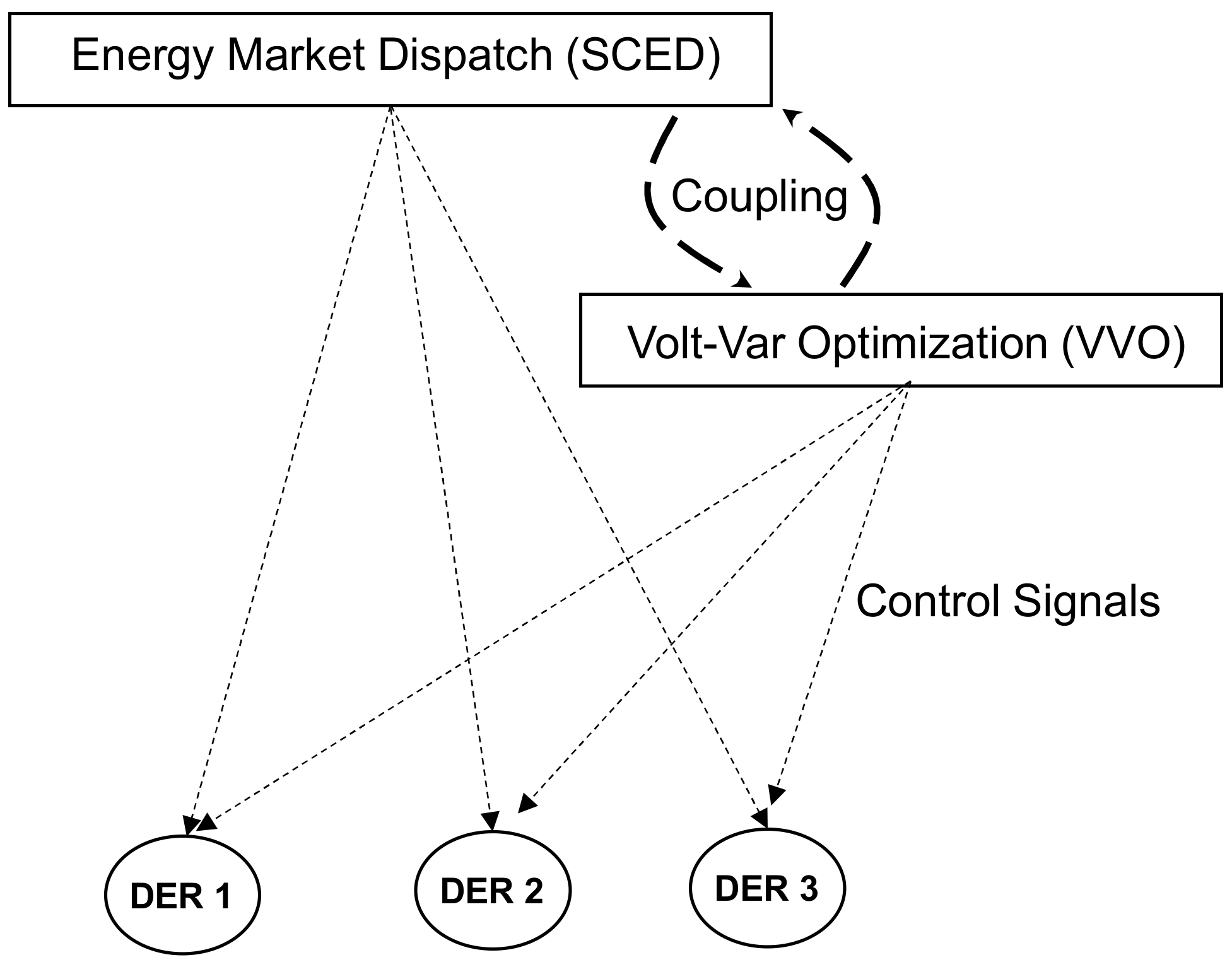
Figure 4, agents connected to the electricity grid are physically coupled and normally constrained in their capabilities in terms of the controlled range of power and voltage. These constraints define an operating envelope for the problem. Consider the following multi-objective DER control problems: energy market dispatch, also known as security-constrained economic dispatch (SCED), and Volt–VAr optimisation (VVO), as illustrated in
Figure 5. The two sub-problems are unavoidably coupled, and there is only a possibility for decoupling with signalling between the two coordinators, that is, information exchange. Without this, the outcome is
sub-optimal for the original multi-criteria problem. Alternatively, if the two controlled behaviours occur over sufficiently different timescales, then some natural decoupling is also possible. This is a fundamental design issue for electricity market architectures and is also highly relevant for the discussion on DERMS.
2.4. Multi-Agent Systems and Agent-Based DER Control
Introducing some level of information exchange, even if only between the nearest neighbours, allows for cooperative action to be used, and this is the principle of agent-based control. The application of MAS theory to electric power systems is an active research area [
21,
22]. Progress in the development of protocols and standardised automation frameworks covers peer-to-peer networking, ad hoc networks, multi-agent systems, object-oriented languages, and client/server models and utilises protocols such as CIM, UDP, TCP, MQTT, MMS, and GOOSE. Existing international standards include IEC 802.11, IEC 61850, and IEC 61499. Other agent-based platforms include LEAP [
46] and JADE, which are described below. More recently, IEEE 2030.5 is being promoted as enabling universal interoperability by utilising public internet infrastructure for DER control and is discussed in
Section 4.
Since MAS and cooperative control are similar concepts, this section provides a brief overview of application development platforms for implementing agent-based algorithms and strategies in power systems. Although there is no universally accepted definition, it is generally understood that an “agent” is defined by the following characteristics:
Autonomy: internal control over actions and behaviour;
Social ability: agent communication language;
Reactivity: interact with an environment, including stimulus and response;
Pro-activeness: goal-directed behaviour;
Reinforcement learning: self-assessment of decisions and performance improvement.
In the context of industrial automation, it is natural to consider “agents” as software objects running code on an application platform, either local or remote to the hardware environment or plant with which they interact—control, monitor, etc.—and an object-oriented approach is common for agent-based software development platforms. However, aspects of distributed coordination may occur at different levels through an interaction hierarchy; for example, the negotiation of channel access or bandwidth may occur at the medium-access control layer of the ISO hierarchy (This refers to the ISO reference model for information exchange in networked communication systems, which consists of a seven-layer hierarchy: 1. physical layer, 2. data link layer, 3. network layer, 4. transport layer, 5. session layer, 6. presentation layer, and 7. application layer. The data link layer consists of two sublayers: media access control (MAC) and logical link control (LLC)).
Importantly, the concept of interoperability is implicit in the above definition. Agents communicating across a common platform using the same language is simple enough. In industrial applications, agents reside on different equipment from multiple vendors, and therefore, the central issue is the agent communication language—in particular, the agreed protocol and ontology for the specific use case. Ontologies allow agents to agree on the meaning of the message syntax for a given context. In the energy sector, this is a key issue for agent-based automation frameworks and the associated standards. Refer to [
21,
22] for a summary of research into MASs in power engineering applications and to [
47] for a discussion on the use of ontologies in the energy area. An example application of MASs for active network management (ANM) in rural networks can be found in [
23], while for an example of distributed Volt/VAr control using MASs, refer to [
48].
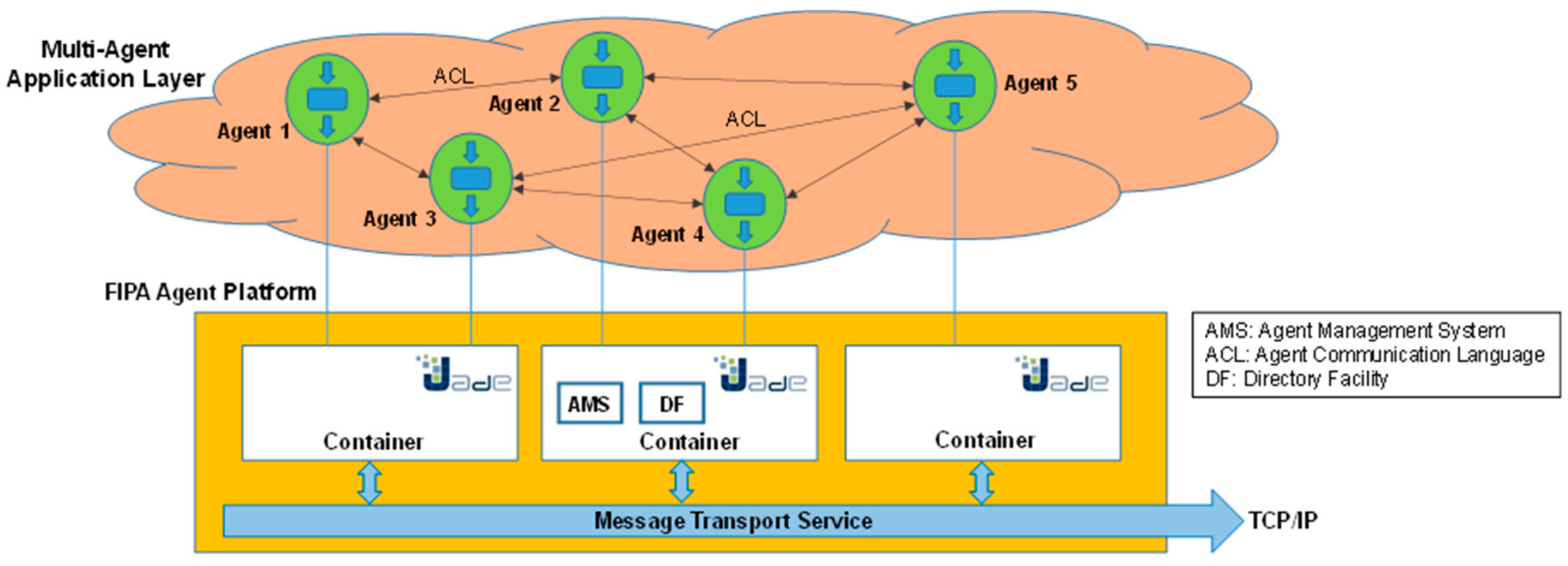
JADE is an example of a widely used, open-source development platform for MAS applications, designed to be compliant with the Foundation for Intelligent Physical Agents (FIPA) specification. Developed using JAVA, the JADE architecture is shown in
Figure 6 below. In the diagram, each running instance of JADE on the computer is called a “container”, which provides a suite of specialised runtime libraries and methods that constitute the software environment in which the agents operate.
Message queuing telemetry transport (MQTT) is an application layer publisher–subscriber protocol that runs normally over TCP/IP networks and is suitable for low-bandwidth machine-to-machine (M2M) applications. Utilising MQTT, a wireless microgrid energy management system (EMS) is described in [
12], which highlights the need for cross-layer optimisation. A comprehensive review of communication technology and its trends is provided in [
49].
2.5. Laminar Grid Architectures
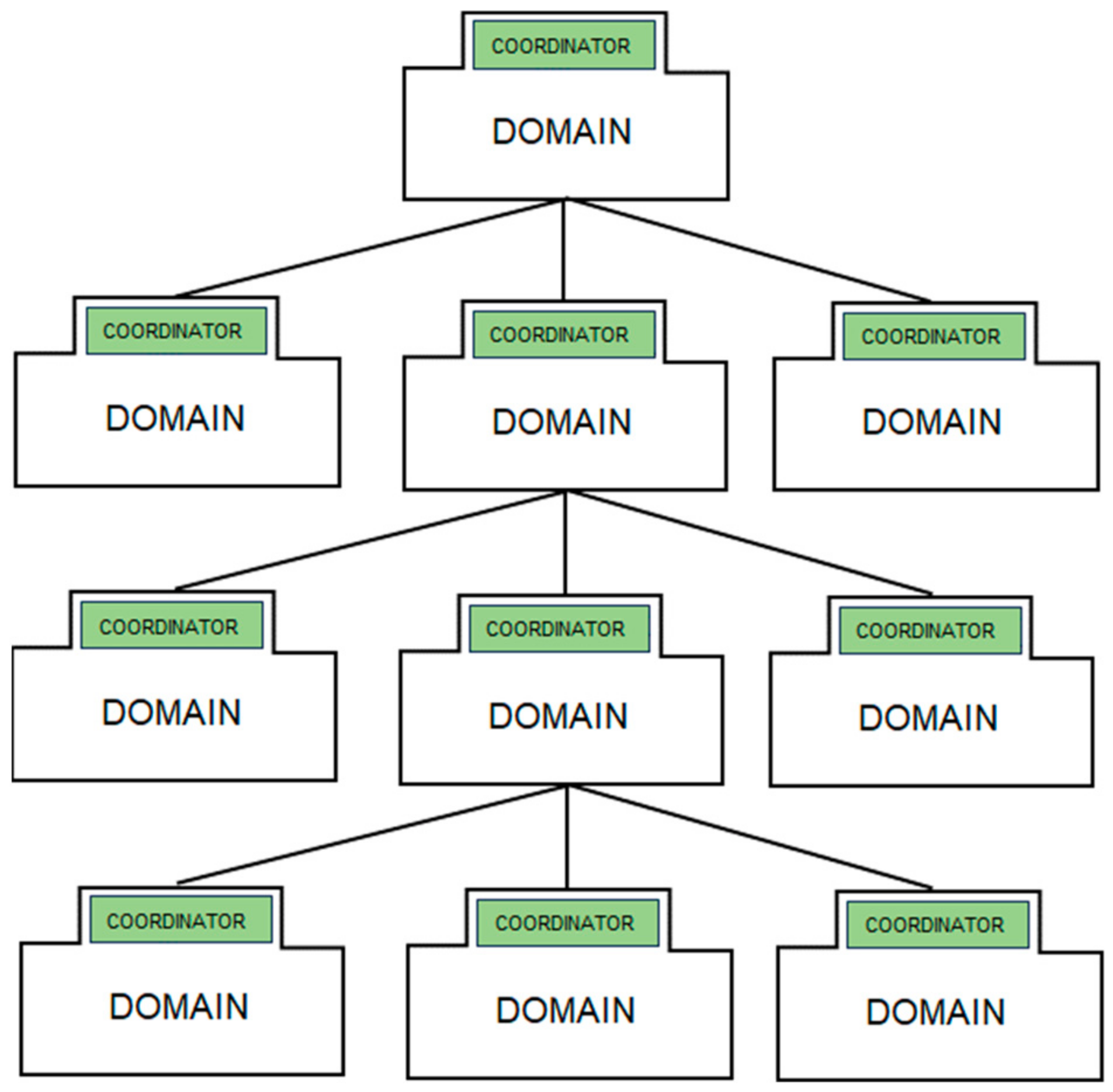
Laminar architecture is a particular approach to distributed control which is based on the functional decomposition of a constrained optimisation problem into a structured hierarchy of nodes; in this sense, it is a graphical representation of mathematical decomposition techniques in optimisation theory, in particular dual or Lagrangian decomposition [
50]. Fundamentally, the approach breaks down a control problem into sub-problems which are solved at each node independently such that the overall system objective is achieved. A natural advantage of this approach to distributed control is close mapping onto electricity grid control structures and their spatiotemporal scaling, which is therefore more intuitive for electrical power system engineers [
51]. The sub-problem is associated with a domain, which might physically correspond to a distribution feeder circuit as an example, and each node has a coordinator responsible for the supervisory control of the node (the definition of a domain is better illustrated via the SGAM model [
52]). An example of a laminar architecture is shown in
Figure 7, while the internal structure of a coordination node is shown in
Figure 8, with the implicit understanding that reference is being made to software objects. Importantly, message passing between nodes should be minimised using the appropriate decomposition coordination, which also assists with interoperability, since the ownership of nodes could be mixed. That the architecture minimises data exchange between nodes is based on the application of information theory. In this sense, the message passing between nodes
is interoperability, and the advocates of this architecture highlight this advantage. Laminar architectures are also being promoted as a possible framework for DER control based on
transactive energy [
9], an idea introduced in the next section.
The communication standard currently being developed by the U.S. Department of Energy and the EPRI for the electricity sector known as OpenFMB is a practical implementation of a laminar architecture.
We have seen that the process of the optimisation–decomposition of a grid control problem results in a structured multi-level hierarchy and a control architecture which can be decentralised. In order to achieve interoperability between the elements of the control architecture, the domains, use cases, and function sets of any proposed information model should have a natural correspondence with the structured hierarchy of the master control problem. This should be a fundamental principle for the design of protocols and automation frameworks. Open loops or quasi-open loops require accurate models, though these problems are more amenable to controller solutions through decomposition–coordination algorithms, while closed-loop control is used for real-time control where less model accuracy is required or no model is available; however, the on-line communication resource requirements are higher.
3. Active Network Management Strategies for DER Control in LV Networks
This section focuses on how a distribution management system (DMS) can be extended to include DER control, with particular application focus on urban and rural networks, acknowledging that various DNSPs have varying capabilities and experience. The topics covered include DER visibility in control room SCADA and, in general, how to enhance the “situational awareness” of DNSP control rooms. It is acknowledged that different members of the ENA DSO working group have adopted strategies based on their unique circumstances and are at different stages in implementing ANM systems.
It needs to be emphasised that active network management (ANM) is not currently utilised for most LV networks, and the operating philosophy of control rooms may differ widely depending on the regional geography, legacy systems and assets, and size of the distribution network area [
19,
20]. Rural networks frequently have no reliable telemetry outside of the population centres. The objective of including this topic area is to provide a context for DER control in terms of several emerging issues facing DNSPs, for example, the forecast of the widespread adoption of EVs, and the implications for rural networks. A recent survey of local DNSPs identified the following industry trends in the operation and control of the network:
Embedded processing;
Ethernet, internet protocol (IP), and MPLS;
Wireless technology advancements;
OT/IT technology convergence;
OT/IT integration.
Compared with transmission networks, the observability of states and controllability of devices on distribution networks are far more limited [
53]. DNSP management systems have historically utilised legacy SCADA and outage management systems (OMS). Remedial action schemes and fault restorations are manual processes where crews are dispatched by control room operators. The shift towards active network management (ANM) by DNSPs as an operating philosophy is being driven by both technological and regulatory changes in the electricity market but also more generally a result of
process automation in industry and utilities. At the enterprise level, the notion of an advanced distribution management system (ADMS) platform has been adopted which integrates a broad range possible operations, including supervisory control and data acquisition (SCADA), geographic information systems (GISs), distribution management systems (DMSs), automated meter reading/advanced metering infrastructure (AMR/AMI), outage management systems (OMSs), distributed energy resources management systems (DERMSs), energy management systems (EMSs), customer information systems (CISs), and meter data management systems (MDMSs). Together, these tools allow for the
optimisation of the settings and instructions which are sent out into the network to achieve the required business-wide objectives.
The DMS is the foundational concept for the topic of DER control and is therefore the technical focus for this section. From a control perspective, the purpose of a DMS is to improve the observability and controllability of an electricity distribution network. In this way, it is a
decision support system for distributors. The core functions which enable a DMS are (i) the distribution SCADA or D-SCADA, (ii) a three-phase unbalanced network model and power flow solver, (iii) the network visualisation screen and operator interface, and iv) information exchange with other systems including GIS, OMS, and AMI. Enabled by this core functionality, a range of advanced applications are available for DNSPs which include but are not limited to the following functional modules [
54,
55]:
State estimation (SE);
Graphical user interface (GUI);
Historical information system (HIS);
Topology processor (TP);
On-line power flow (OLPF);
Intelligent alarm processing (IAP);
Short-circuit analysis (SCA);
Switch order management (SOM);
Volt–VAr optimisation (VVO);
Fault location, isolation, and service restoration (FLISR);
Predictive fault location (PFL);
Optimal network reconfiguration (ONR);
Short-term load forecasting (STLF);
Dynamic equipment rating;
DER management (DERMS);
Demand response management (DRM);
Emergency load shedding (ELS)
Engineering analysis;
Dispatcher training simulator (DTS).
Unlike transmission system operators, where network analysis tools such as state estimation are critical for the security-constrained dispatch of the market, network analysis for distributors is primarily for voltage regulation and switching operations. Network modelling for distributors is complicated by greater levels of imbalance at the distribution level, the lack of line transposition, and the presence of single- and double-phase laterals. Typically, the level of instrumentation on the LV or primary side of the network is sparse so that SCADA coverage is limited, which makes voltage regulation a challenging task. Another problem is how to disaggregate the consumer load profile from the DER output. In principle, using an LV feeder model and real-time measurements, the real and reactive power flows at customer connection points required to restore voltage profiles to within the prescribed limits can be calculated. It is precisely this information gap that is the central challenge for DER control.
The distributed energy resource management system (DERMS) is an advanced application for a DMS, which though available as a stand-alone software package, in practice, encompasses a range of possible solutions for how a DNSP can integrate DER control. Critically, the extent to which a DNSP can successfully implement a DERMS is contingent on the adequacy of a range of supporting legacy infrastructure, in particular the following factors:
The visibility and controllability of DERs on the LV network, where telemetry coverage may be poor or inadequate for the intended function as, for example, on rural networks.
Contractual arrangements for DER owners need to be considered, which can change over the lifecycle of the customer connection.
The need for certified end-to-end interoperability, that is, from the DMS application to the DER point of connection. Not all vendors can demonstrate the necessary level of compliance.
The salient point is that for the above reasons, DERMS vendors often need to provide a suite of software and hardware solutions at all levels of the distribution network hierarchy, and across the enterprise, which can be cost-prohibitive for an organisation to implement. Given the above considerations, distributors can instead manage DER connections on a case-by-case basis, and since network augmentation is expensive, there may be options to introduce a managed interconnection at a particular location. This might avoid an expensive upgrade. Simple examples are the tele-metering or transfer-tripping of the grid connection. Based on the level of enterprise integration, some vendors differentiate between a fleet DERMS, edge DERMS, and a central DERMS, which has full integration capability.
Since there are large numbers of DERs connected to the LV network in each franchise area, or even along a single feeder, the core function of the DERMS is DER coordination or orchestration to achieve a particular operational objective. In practice, this can be a highly complex task which is far more than simple aggregation, and becomes a nonlinear multi-objective optimisation problem which must be solved by the DERMS in near real time. For example, consider Volt–VAr optimisation (VVO) along a feeder. In this example, coordination may be required between voltage regulators at the transformer, switched capacitor banks, and smart PV inverters which may be connected at various locations on the circuit. There are a range of technical constraints that need to be considered relating to thermal and voltage ratings, possibly using dynamic ratings. Ultimately, a DERMS should enable DER integration to the extent that DER parameters and behaviour simply become attributes at the circuit or feeder level.
Given that the volume and diversity of information received by distribution networks is rapidly increasing, there is a general question as to the
operating philosophy of future control rooms, and system operators are leading this work [
19,
24]. It is clear that with the volume of alerts, alarms, and measurements being received that some level of
pre-processing is required, which is a natural application area for expert systems and machine learning tools. Some equipment static limits may instead become dynamic limits. There is a preference for modular and open architectures; for example, DER management modules might sit outside the existing control room SCADA or DMS. Based on feedback from DNSPs in Australia, the more fundamental issue relates not to the urgency of adopting DERMS but more generally to the visibility and controllability of devices—including DER plants—on the LV network. As the operating philosophy of the LV network is different to the MV network, this might be addressed with a dedicated DMS which is external to the control room and solely responsible for the LV part of the network. For example, some distributors are already utilising AMI data from customers in their LV network operation and modelling [
56]. In rural networks, DER control frequently requires a more bespoke solution for communication and control, and interoperability solutions are discussed in
Section 4. For the class of DER plants in the range 100 kW–5 MW, which include commercial and industrial owners, DNSPs may have existing engineered solutions for managed interconnections. For this reason, there is a natural inertia to adopting DERMS for some DNSPs.
Enterprise DERMSs normally include a level of predictive constraint management that can forecast possible network violations and schedule requests for active support to groups of DERs. Managing the aggregate behaviour of a DER group may be highly complex depending on the control objective, network topology, local asset constraints, customer contractual arrangements, etc., and for this reason, mapping enterprise DERMS functions to DER functions can be problematic (the DNSP might also be managing multiple network issues simultaneously using DER control). For example, DERMSs have no “standard” feature for utilising PV inverters to regulate voltage along a particular feeder. However, the mapping of inverter functions to DERMS-level functions, as shown in
Table 1, could be considered. This could be considered a guide for how a DERMS might be utilised by distributors to implement certain active management functions. In this way, DNSPs have a set of unique existing and future control problems for their network that need to be properly defined before deciding whether a DERMS has the required function set or whether a more bespoke DER control solution is required. The EPRI and the US Department of Energy have published several guidelines and manuals relating to the integration of DERs into DMSs, and the reader is referred to [
57,
58,
59].
3.1. Enterprise Level DER Management Platforms
It is not in the scope of this report to review commercial DERMS software platforms, simply to note that product offerings differ widely in their level of enterprise integration. Interoperability with legacy SCADA is a central issue for most distributors, which in itself may in practice limit the vendors, as would the availability of local resources to support the deployment. More importantly, in addition to the IT issues associated with a DERMS application server on the computer network, solutions may also consist of field-deployed gateways, IEDs, etc., which run software clients at the grid edge or behind the meter. As such, there are O&M considerations related to access, firmware updates, and end-to-end integration testing. Other useful features for a DERMS might include a programming or scripting language so that DNSPs can develop their own applications and a capability for modelling and simulation. Vendors of DERMS-related solutions include ABB, GE, ETAP, OATI, Comverge, Oracle, Schneider, OSI, Aclara, Enernoc, Siemens, Smarter Grid Solutions, Spirae, AutoGrid, SwitchDin, GreenSync, and QualityLogic. Vendors can provide solutions which encompass the whole DER lifecycle or specific tools which enable interoperability with existing standards. The DERMS might also include a direct
market interface in certain cases. Since in most circumstances DER owners will be contracted to an associated market participant, retailer, or aggregator, it is natural that DER control actions should be optimised from a market perspective. In other words, control actions should align with consumer preferences. This type of DER control is also known as
transactional energy control, which is discussed in
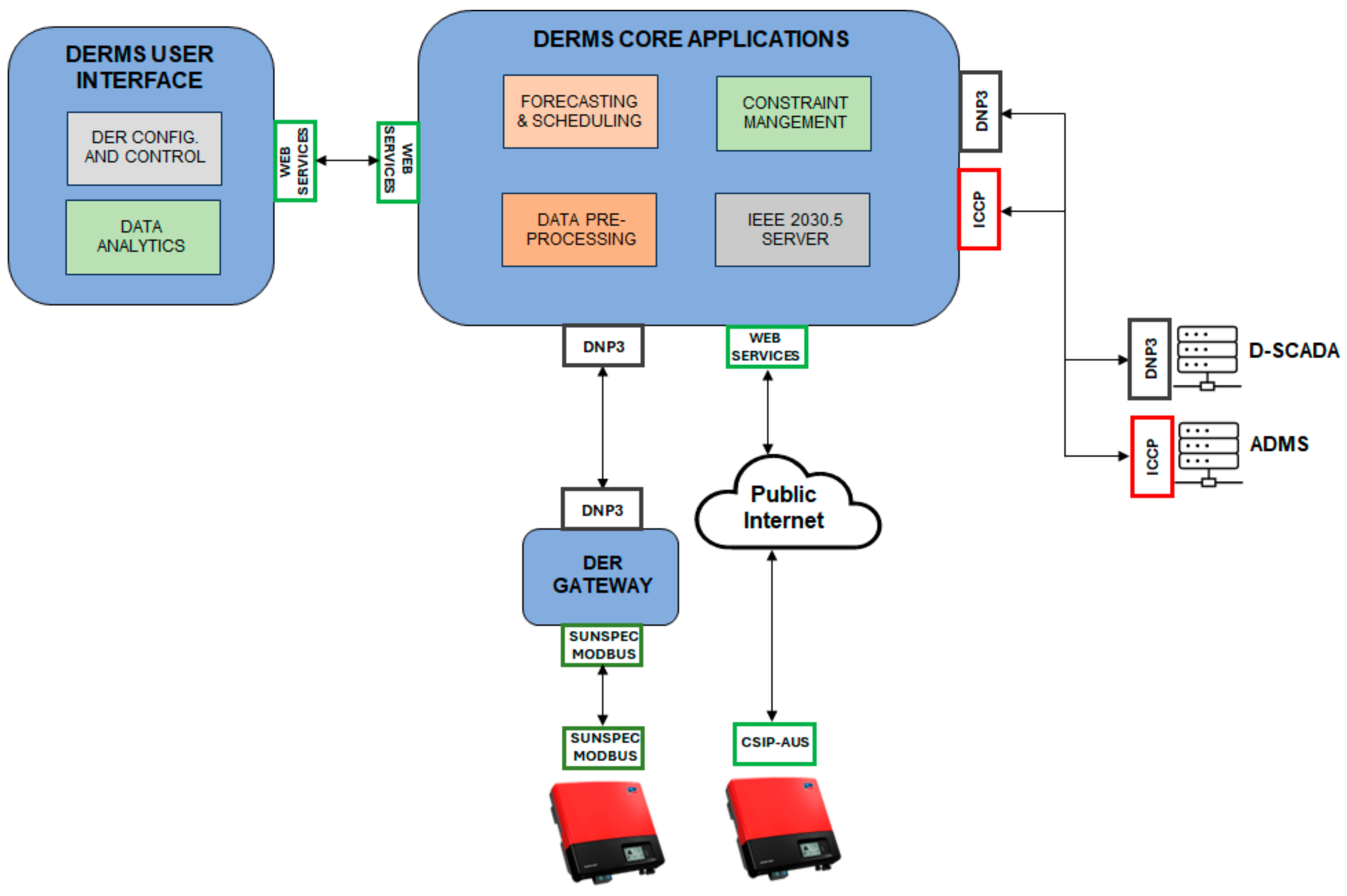
Section 5. An example architecture for an enterprise-level DERMS is shown in
Figure 9.
3.2. Remedial Action Schemes
3.2.1. Fault Location, Isolation, and Restoration (FLISR)
This subsection provides a brief overview of DER control strategies during remedial action by DNSPs. Remedial action schemes include fault location, isolation, and restoration (FLISR), which includes the more recent notion of “self-healing” schemes, and black start following a system outage. These are advanced grid automation functions being trialled through DMS and DERMS applications at an increasing number of DNSPs. Several recent pilot projects have demonstrated the use of both distributed “peer-to-peer” architectures such as multi-agents systems (MASs) or laminar architectures for FLISR that incorporates DER control capabilities.
At the conceptual level, FLISR may be considered as an optimisation algorithm which determines the best sequence of switching actions that, after a fault, restores power to the greatest number of customers, in the shortest possible time frame, while maintaining voltage level and flow constraints on the network. For network circuits with embedded PV or energy storage, it is possible the FLISR algorithm cannot find a feasible solution without some DER control actions. This could take the form of transfer-tripping a PV system, curtailing the real power output, or issuing charge/discharge instructions to a battery energy storage system (BESS). For an islanded segment, this might also entail fine adjustment to the BESS phase or voltage, so that grid re-synchronisation can occur. The salient point is that the mode of DER control will depend on the interoperability functions available, for example, a transactive energy signal to the DER, rather than an external reference command.
As circuit breaker relays and reclosers increasingly provide setting groups which allow the relay to adapt to dynamic network topologies and bi-directional power flows, similarly, DER inverters might, in principle, be equipped with group protection settings. Allowing these devices to exchange information on their status within a group or segment then introduces a level of “topology awareness” in these devices. This highlights the need for further advancement in inverter controls and interoperability standards.
The following example illustrates this concept (an ongoing full-scale demonstration of distributed DER control for FLISR is currently being conducted by the U.S. DoE, the PNNL, the NREL, and Duke Energy). In this example, DNSP devices including reclosers and circuit breakers have integrated remote terminal units (RTUs) based on commercial-off-the-shelf (COTS) hardware, while PV inverters and BESS hardware, that is, non-DNSP devices, are controlled through COTS hardware controllers implemented as open-source VOLTTRON nodes or gateways. A distributed control architecture is implemented using over 100 DNSP-owned cellular LTE nodes (for the use of 5G for cellular nodes, refer to
Section 6.2.5). The communication protocol is the OpenFMD message bus, or “OpenFMD Harness”, which is a publish/subscribe peer-to-peer protocol. The OpenFMD protocol supports interoperability between DNSP and non-DNSP devices and is designed around a laminar architecture.
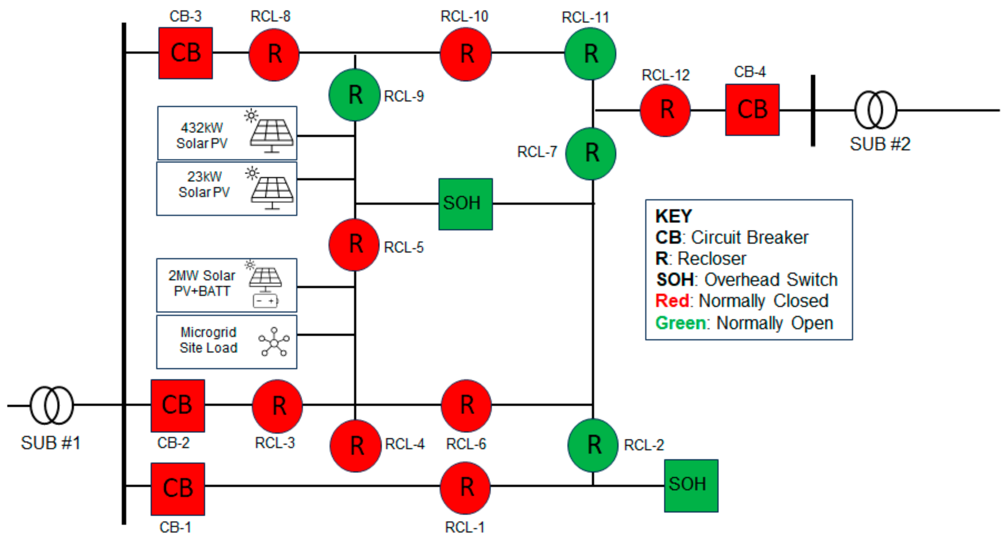
For this operating case, a permanent line-to-ground fault on all three phases occurs in the segment bounded by RCL-8, 9, and 10, as shown in
Figure 10. As a result, RCL-8 initially isolates the fault and eventually opens in a locked-out state. RCL-8 then publishes its change in status on the message bus, while all other devices which have subscribed to this information process the message and decide whether a change in settings is required. Once this step is completed, the DMS will run the FLISR algorithm to determine the optimal switching sequence if a feasible sequence can be found. In this scenario, there is no feasible switching solution without actively controlling the DER in the system, which in this case includes PV, BESS, and a microgrid. Therefore, a transactive energy signal is published to all the DERs to incentivise behaviour which will increase the available switching options. Importantly, this incorporates DER-DER transactive signalling, where this has been implemented. The final system configuration after the remedial actions are completed is shown in
Figure 10.
3.2.2. Microgrids
Microgrids (MGs) are an increasingly important topic and are now active, with several DNSPs already managing MW-scale microgrids within their franchise area. In some cases, microgrids are being trialled for the planned islanding of customer groups or segments. For rural and regional networks, their use for isolated supply to towns and communities is now very well developed. As such, the topic of microgrids is not the focus of this report; however, certain remarks are relevant with respect to
DER control and microgrids. In major practical implementations, the automation of microgrids is supervised locally through a
microgrid controller, frequently associated with an energy storage system (ESS), for power balancing during autonomous operations. Several vendors supply microgrid controllers as COTS equipment. Similarly, enterprise DERMSs usually support the integration of microgrids at some level [
55]. A microgrid will have a point of common coupling (PCC) to the parent network, and disconnection and re-synchronisation are usually managed by the microgrid controller or other
intelligent connection agents embedded in a relay or circuit breaker. Since the microgrid PCC may not be the same as the ESS grid coupling point but could be remote, at a circuit breaker or recloser, at the end of a feeder, then re-synchronisation requires a coordination strategy. For example, two such strategies are known as
active and
passive re-synchronisation, with the former a centralised strategy and the later a decentralised strategy. Similarly, during an autonomous operation, the DER
control philosophy for residential customers embedded within the microgrid may need to be updated due to reliability or system security considerations since the topology of the network has been altered (in particular, for DERs operating in a microgrid,
frequency control is a key consideration. Similarly, a different set of constraints must be applied during operation as a microgrid). In some instances, the DNSP communicates to the DER directly or indirectly through the microgrid controller, while other control schemes support distributed peer-to-peer networking. In a nutshell, microgrid control architectures include the DER control architectures that have been previously discussed in
Section 2. The more important issue relates to how interoperability standards, such as IEEE 2030.5, will incorporate microgrid function sets and controls, which are currently under development (the DEIP currently has no dedicated microgrids WG. In general, the ARENA focus has been rural and regional MG).
3.3. Voltage Profile Management for PV-Rich Distribution Networks
DNSPs utilise various network assets to regulate the voltage along feeders, including on- and off-load transformer tap changers, switched capacitor banks, static VAr compensators, power factor correction equipment, and ultimately, network augmentation. For feeders that host significant PV capacity, which is becoming increasingly common, maintaining an adequate hosting capacity for additional customers frequently requires some or all of the PV inverters to take some corrective action. The corrective action may be a local control action, for example, Volt–var control, or an external signal to the inverter, for example, a real power curtailment command, or a combination of local and external control. Local voltage control settings are prescribed in the inverter standards and also in jurisdictional guidelines (for example, in Victoria, the “VicSet” inverter settings for Volt–Watt and Volt–VAr response modes are more stringent than those prescribed in AS 4777.2 [
56]), while the source of an external control could be the DNSP, aggregator, or other responsible market participants. If we consider local voltage control by the inverter as a primary control action, while external control is the secondary action, then, in this sense, we have a hierarchical control scheme. DNSPs have a number of strategies and deployed network assets they can utilise to improve hosting capacity, including DER control. A comprehensive overview of voltage control and hosting capacity was provided in the report [
60], and as such, this topic is not considered here. Instead, several practical issues for using DER control to manage voltage on a PV-rich feeder are considered, and the different approaches from a control system architecture perspective are investigated. This will highlight several important design considerations for DERMS-based control strategies for PV-rich feeders.
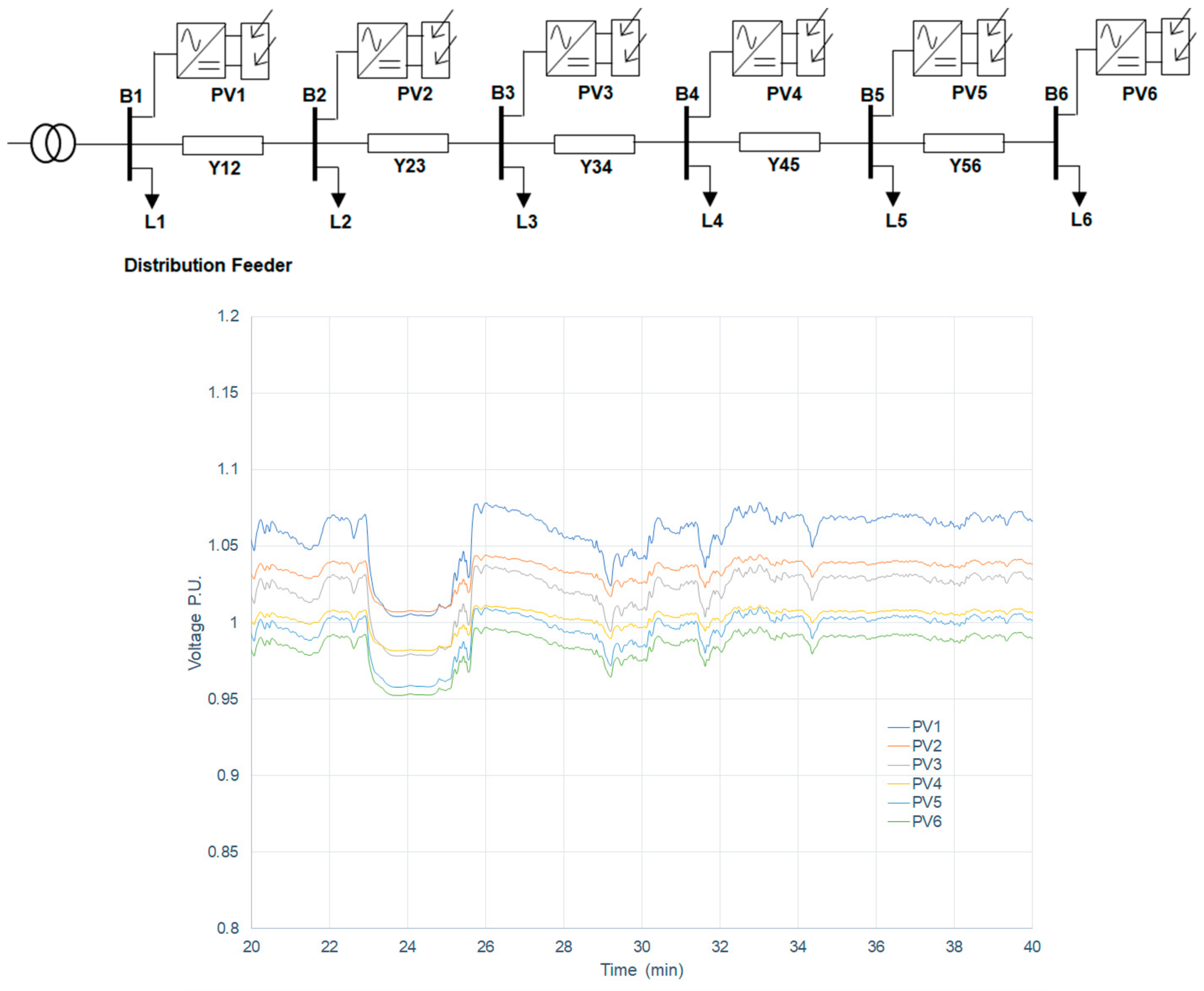
Referring to the example shown in
Figure 11 below, which illustrates a PV-rich feeder scenario consisting of seven connected systems along the length of the feeder (assuming larger residential systems and noting commercial-scale PV will change the voltage appreciably), if the measured voltage profiles at each connection over a 20 min period are considered, then a voltage gradient along the feeder which is line impedance-dependent is apparent, and a fluctuation over time which appears to be stochastic but is related to the irradiance level can be observed. The degree to which the voltage changes also depends on the voltage sensitivity characteristic of the feeder. It is natural, therefore, to consider firstly over what
timescale the voltage is to be controlled, and secondly, how the PV inverters should be
coordinated as a group to achieve the desired performance (i.e., through operating constraints such as contracted power, inverter capacity, and operating envelopes). In general, a combination of local inverter control, or primary control, and external control, or secondary control, is required to restore the voltage to within the nominal range. The effect of interacting control loops is detailed in [
61]. It is seen that the advantage of multi-level hierarchical control structures relates to the partitioning and decoupling of the dynamic behaviours at different timescales. This provides more degrees of freedom for the DER controller to adjust its response and therefore attain the desired voltage behaviour along the feeder [
62].
Distribution networks often have limited options for real-time voltage control. One strategy for voltage reduction is Volt–VAr optimisation (VVO), which may be considered a multi-stage process where the first stage utilises on-load tap changers at the distribution substation to shift the profile downwards and then uses switched or static VAr elements, including DERs, along the feeder to flatten the profile. While PV inverters can provide VArs for voltage control, the above paragraph highlights the complex factors to be considered for a DERMS-based control system. In principle, if the DNSP has a perfect physical model of the electrical network and accurate forecasts of load and irradiance, then the appropriate levels of real and reactive power injections could be calculated using power system simulation software and then despatched to each DER. This could be considered a form of model-based secondary control of voltage. This is also the operating principle behind dynamic operating envelopes (DOEs). There is currently a strong research focus on this mode of secondary control using IEEE 3050.5-based architectures, while distribution network models based on AMI data are also being investigated.
There are two important observations based on the control scheme that is shown in
Figure 12, which shows a simplified representation of centralised model-based control. Firstly, as a DER control technique, it is a
centralised approach, while the trend in control architectures is moving towards
distributed models, which is a central theme of this report. Secondly, since it is an
open-loop scheme for secondary voltage control, it depends critically on the accuracy of the physical model of the network. As such, two areas of innovation in DER voltage control (control of voltage) include, for example, distributed model-predictive control (D-MPC), and cooperative multi-agent systems (MAS), which are inherently decentralised methods where the control action is
distributed. Aspects of this were investigated in the recent Distributed Dynamic Limits (DDLs) trial [
63]. DER interoperability frameworks and standards, which are discussed in
Section 4, need to support distributed architectures. It is still an open question as to whether a closed group of DERs can effectively emulate the voltage control steps of the control room, and it is assumed a level of supervisory control by the DNSP is still required, at least for remedial or emergency action outside the safe operating limits.
Physically realizable communication schemes are
all subject to some latency in data transmission, and time delays can impact the stability and performance of a voltage control system. As an example, a recent study by Sandia National Laboratories [
64] investigated the effect of communication time delays on VVO using PV reactive power control on a feeder. Voltage regulators using OLTC are electro-mechanical systems, which are not in general fast acting. Normally, the timescales over which inverter external VAr control occurs is an order of magnitude faster than OLTC voltage regulation. As such, the two control schemes are effectively de-coupled. The communication delay is defined as the latency of packet transmission, while the communication interval is the time period between transmissions. If the inverter communication latency is increased from seconds to minutes, the number of tap changes will rapidly increase. This results in accelerated degradation and increased maintenance costs. For optimal operation, the inverter communication delay needs to be faster than the 30 s voltage regulator delay on the transformer. In
Section 6, emerging developments in cellular and satellite radio technology for DER control are discussed.
3.4. Australian Distribution Network Experience with Pilot Projects for DER Control
Australian distribution networks are characterised by a combination of highly interconnected and meshed networks around the capital cities and urban zones, combined with more sparsely connected radial networks in urban and rural areas which have long feeders and an extensive network of single-wire earth return (SWER) systems which supply remote customers. In general, LV distribution networks have poor visibility and control capability. Rural networks frequently have no reliable communication outside of the population centres, so remote telemetry is often unavailable. These networks are poorly resourced with a low revenue per km of network, so that dedicated communication infrastructure is not feasible. In this regard, a notable DER control pilot is the Decentralised Dynamic Limits (DDLs) for managing network constraints for DERs on rural and remote networks in NSW [
63]. This project successfully demonstrated a decentralised DER control framework which is fully autonomous and requires no DNSP control room supervision that addresses several of the challenges mentioned above for rural networks.
Australia has experienced an exponential growth in rooftop PV systems over recent years and now has the highest global installed capacity of residential PV systems relative to population size which has created several challenges for managing distribution networks. During normal operating conditions, some feeders are seen to exceed allowable voltage limits and experience reverse power flows. Due to this growing problem, Australian DNSPs are actively investigating measures to enhance PV hosting capacity during the day such as the South Australian Flexible Export Limits for Solar PV Trial and, in Queensland, the Energex Dynamic Customer Connections program [
65]. For all these projects, a control architecture based around IEEE 2030.5 has been adopted and re-named as the Common Smart Inverter Profile Australia or CSIP-AUS, which will soon be mandated in the DER Technical Standards. The notable lessons learned from these trials highlight some of the issues outlined previously, such as an inability to accommodate dynamic changes to the network topology and DER group membership and an inability to resolve multiple network issues simultaneously. This is partly as result of an incomplete knowledge of forecast network events. There were also performance issues relating to latencies and time delays in the communication and scheduling of DER requests, which can cause a race condition to occur.
The legacy voltage standard in Australia is 240V which has since transitioned to align with the recognised IEC standard of 230V. This presents challenges for DNSP voltage management regimes which includes DER control, and inverter PQ mode settings have been adjusted in some jurisdictions to ensure voltages are maintained within the allowable range. An example of this is the Victoria Voltage Management for PV-Rich Distribution Networks, where the DNPS is investigating a range of local voltage regulation measures including a combination of network-based solutions and DER control through modified PQ mode settings [
63,
64].
Several remote towns in Western Australia and the Northern Territory are isolated from the main grid and supplied by utility-owned diesel power plants and separate electricity networks. These remote towns are considered as part of the distributor’s total managed network area, and therefore, customers are entitled to the same levels of reliability of supply, regardless of the location. This presents a challenge for DER control by the DNSP and is an important consideration in the selection of a DERMS. The Onslow pilot project in Western Australia where the DNSP was Horizon Power involved the design and implementation of a unique DERMS architecture to address these challenges. The system was required to calculate and transmit dynamic operating envelopes (DOEs) to DERs on remote parts of the network [
66].
At the bulk power system operator level, AEMO and ARENA have several projects trialling various DER market integration methodologies for both DER participation in the wholesale energy market and also the market for network services, which are used to manage system constraints. Scenario modelling suggests that by 2050, over half of dispatchable capacity in the electricity grid will come from coordinated DER storage. In this regard, AEMO is introducing new scheduling and dispatch rules for small-scale DERs known as flexible trading arrangements (FTAs) and Reliability and Emergency Reserve Trader (RERT) arrangements for DERs to provide emergency demand responses [
67]. Two notable pilot projects are using DER services to manage local constraints. Project Converge utilises what are known as shaped operating envelopes (SOEs) to dynamically allocate connection capacity to DERs (via an aggregator or trader) which uses a similar method to how capacity is allocated to large generators at the bulk transmission level. In contrast, for Project Edith, the DNSP calculates and sends to each DER (via an aggregator or trader) a real-time dynamic network price (DNP) together with a dynamic operating envelope (DOE) which define the guardrails of the allowable DER power injection limits. The objective is to provide DER owners with pricing signals that reflect real-time energy flows and constraints on the system. The lessons learned and limitations of the market integration trials serve as examples which illustrate the design considerations for DER control architectures in this paper. Specifically, there can be conflicting priorities as DERs are required to provide several market services simultaneously and highlights the problem of coupling across timescales. This is in part solved through more accurate forecasting which allows DERs to anticipate and therefore optimise the provision of services. Secondly, the information architecture is normally based around a data exchange or hub that operates as a data server for participating DERs. As previously described, there are key advantages in utilising a decentralised or distributed architecture. However, the digital systems to enable this is not well developed or too expensive. It was also observed that residential DER owners who agreed to participate in the trial had more interest in retaining behavioural control over the DER asset, while C&I customers preferred automated control due to the ease of operation and lower cost to operate. In summary, there does not yet exist a consensus approach to DER market integration with differences between the DNSPs’ approach to the problem. There is not yet a functioning transactive marketplace for DER network services, and specific tranches of customers are highly engaged with the DER programs.
4. Interoperability: Progress and Challenges
This section provides an update on the current status of technical standards related to the automation, grid connection, and interoperability of DER equipment. This is an important and broad topic area which needs to include not just progress in the development of the standards but also the progress of vendors in ensuring the compliance of their products. Given there are multiple interoperability projects currently in progress, this is a highly contested area, which has important implications for the ability of DNSPs to control DERs. Progress in this area is being driven by consumer electronics and ICT technological innovation, and the regulatory and compliance framework is increasingly complex. Ultimately, a “plug-and-play” solution for DER control is the objective.
4.1. Types of Interoperability: Protocols, Models, and Standards
The focus of most interoperability projects relates to information exchange between devices or systems, while the coordination and interaction between devices also has
functional interoperability considerations for the engineer. In a practical sense, this allows for the simplification of the process of programming and integration of devices, which is generally required for most grid automation projects. The ESB interoperability policy directions report [
1] provides a good overview of the challenges for DER interoperability. According to the report, interoperability is defined according to a hierarchy of the following attributes:
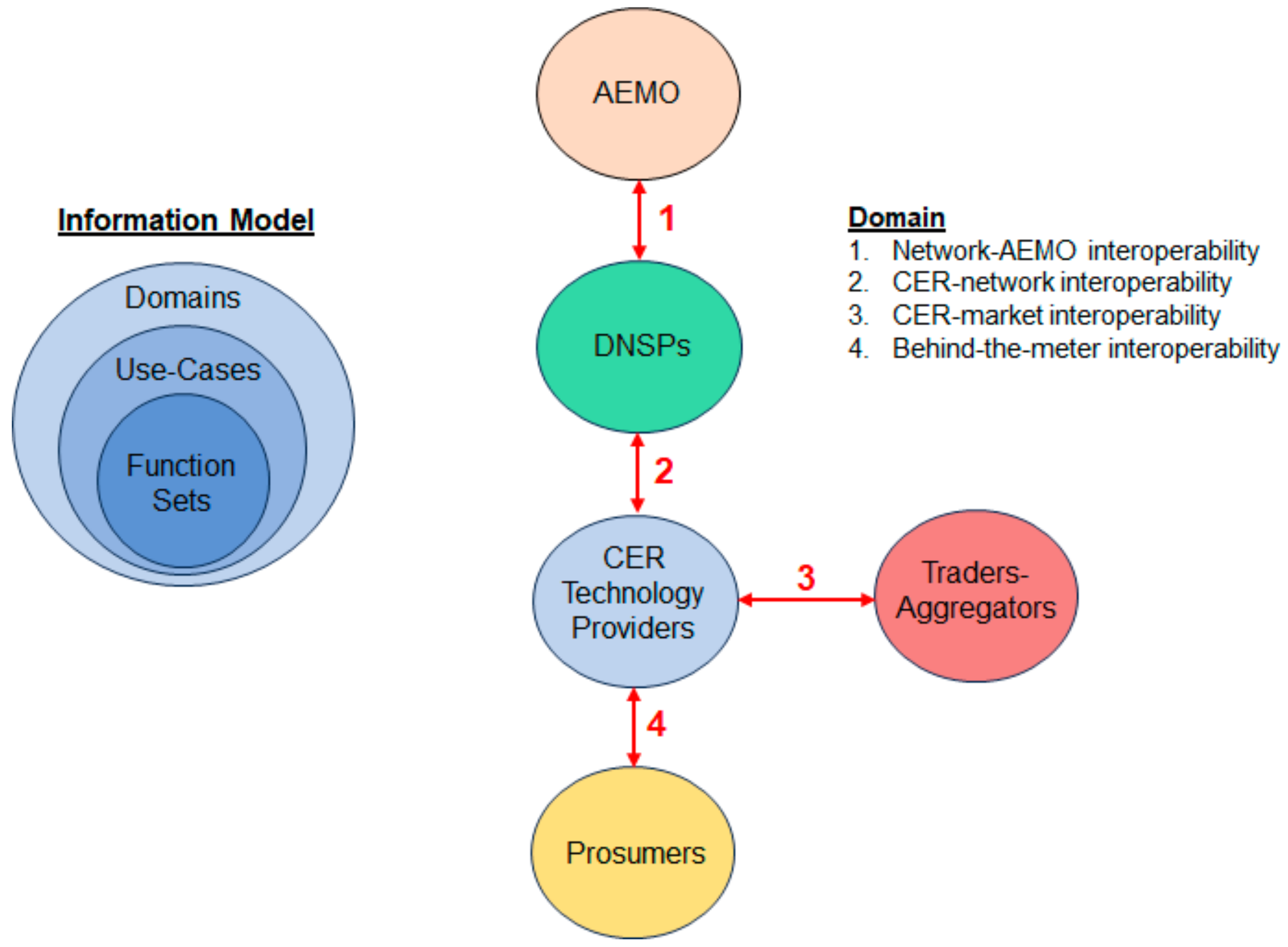
Domains: this defines the parties in the communication exchange;
Use cases: this defines the purpose of the communications exchange;
Feature sets: this defines the functions provided for in the communications exchange.
These definitions are illustrated in
Figure 13 below. As expected, there is a close mapping of this definition with the CSIP-Aus/IEEE 2030.5 protocol, which is also consistent with the IEC61850-related standards for grid automation. As such, it is consistent with industry trends.
The conceptual framework for interoperability described by the Energy Security Board (ESB) is useful in this regard as it encompasses most of the generally accepted notions of interoperability. The two domains most relevant for this report are the CER-network and CER-CER, or behind-the-meter, interoperability domains. Importantly, CER-CER interoperability needs to consider multiple use cases, including inverter-to-inverter, inverter-to-gateway, meter-to-inverter or -gateway, and load controller-to-inverter or -gateway use cases. Other devices which must be included in CER-CER interoperability are home energy management systems (HEMSs) and increasingly EV inverter/chargers.
In no small measure, much of the urgency relating to the technical governance of interoperability in the electrical power system is due to the rapidly expanded role of residential- and commercial-scale PV and energy storage in the generation mix. Although there are various interoperability projects underway in multiple jurisdictions, the development of an accepted “interoperability framework” for DER control remains a work in progress. In general, we can identify the following emerging approach to interoperability for DER control. This interoperability model requires the use of gateways at the grid edge, which have embedded automation and control capability, i.e., distributed intelligence, and support multiple communication protocols and ports. A single gateway normally communicates with a group of inverters using a more efficient register-based application-layer protocol such as SunSpec Modbus or DNP3 and normally supports a lightweight TCP/IP-based protocol such as IEEE 3050.5, MQTT, or OpenFMB for either peer-to-peer communication or, more commonly, between the gateway and a data server at the DNPS. In line with recent trends in software code development and computer networking, most TCP/IP-based protocols being applied to DER control have rich data models and semantics that are consistent with an object-oriented, hierarchical approach.
The proposed protocol for CSIP-Aus, which will also be used to communicate operating envelopes to DER, is based on IEEE 3050.5. This is an application layer IP-based protocol based on a REST (REpresentational State Transfer) architecture, which is a lightweight stateless protocol, based on a client–server model. The “representational” aspect refers to the API which is presented as an XML schema, while the underlying protocol is HTTPS (secure hypertext transfer protocol, though security is discussed in a later section). The main advantage of this architecture is that there is no need for the client or server to keep track of previous messages to interpret the current message. The benefits of using the public Internet for DER control in terms of scalability and access are self-evident. The designers of IEEE 3050.5 have intentionally used an information model which is closely aligned with the IEEE 61850 data model.
The protocol is hierarchical and uses function sets to define a group of resources, examples of which include controlled loads, PV inverters, or EV changers, which are grouped according to the responsible market participant or network topology. After the initial request by the DER client to the DNSP sever, which registers and configures the DER functions, the communication enters steady-state operation, during which the inverter client will periodically “Get Controls”, “Send Metrology”, and “Send Status” to the DNSP server. The definition of a “Control” is flexible and includes set points, curves, or programs. A subset of control functions can be scheduled as events, with a start time and finish time. The primary use case for time scheduling is flow control, such as for the charging and discharging of energy storage during specific time periods of the day.
The purpose of IEEE 2030.5 was not intended to replace distribution SCADA, and its timeframe of operation is seconds or minutes. As such, it is appropriate for secondary- or tertiary-level control of the inverter. However, there is no fundamental reason it cannot be utilised over sub-second timeframes, and future use cases might allow for fast DER control or peer-to-peer communication which, for example, might be possible with stand-alone 5G. Presently, to implement fast inverter control over a communication network would normally require a nearby gateway, PLC, RTAC, or a similar hardware controller, with a dedicated network connection to the local group of DER. As a transport protocol for industrial automation, TCP/IP has disadvantages that include its “slow start” and nondeterministic latency, compared to, e.g., UDP/IP. The salient point regarding IEEE 2030.5 is that it is open and flexible; it has the advantages of a purely command-based serial protocol such as Modbus and a purely information-based protocol such as open ADR. This is, to an extent, the reason for its widespread adoption for DER control.
As a final remark, with regards to interfacing DERs with DNSP DMS or SCADA, without explicitly using a DERMS server, there are several open standards for industrial automation such as object linking and embedding for process control (OPC) that can often provide a simple
software gateway between DERs and SCADA. There are specific vendors that provide an OPC server for this purpose (refer to
Section 4.2 on open-source platforms). An alternative proposal relates to developing a standard user API for inverters based on IEC 61499 functional blocks, which is used for application development with electric drives and machines, and some work has been completed on
programming interfaces for power system automation using both IEC 61850 and IEC 61499 [
68]. An important practical issue in this regard relates to inverter function and
user access. Some manufacturers provide a hierarchical access regime, and this is both a cybersecurity and power system security issue.
A list of the current interoperability standards for DER is provided in
Table 2. The challenge for inverter manufacturers is to develop flexible modes of function and control, which both anticipate future applications in grid management, without compromising the safe and reliable operation of the inverter and can produce predicable behaviour at the point of grid coupling. This is a fundamental challenge for DER interoperability.
4.2. Open-Source Software for Development, Testing, and Validation
It is a common theme of this report that future grid architectures which enable DER control will need to achieve seamless end-to-end interoperability, and this is a core challenge for standards development and in particular testing regimes. While specific aspects of device behaviour and compliance may be demonstrated through certification, e.g., AS/NZS 4777.2:2020, SunSpec Modbus, CSIP-Aus, CE, etc., for DNSP field deployments, it is primarily the end-to-end interoperability between the control centre (CC) and the DER that is of practical interest to the engineers and operators. It is important that the effect of control signals on voltage and current at the point of common coupling (PCC) reflects the expected behaviour. In this regard, several private and government funded research is directed toward developing open-source tools for utilities to investigate and develop their own DER control platforms, these include IEEE 2030.5 Client/Server [
91], OpenFMD Client/Server, GridAPPS-D [
92], OpenDSS, HELICS, VOLTTRON, Envoy Gateway API, and Java Agent Development Environment (JADE). The advantage of such an approach allows utilities to develop and pilot DER control solutions, without investment in an enterprise-scale DERMS platform. Other projects have developed test-beds using hardware in the loop or co-simulation to evaluate DERMS platforms [
93,
94].
5. Trends in Inverter Design Architecture and Functionality
The recent ESB directions paper on DER interoperability makes the salient point that “without careful consideration and management, standardisation can stifle innovation by locking in arrangements that inhibit the future developments…there is an inherent tension between the benefits and risks of standardisation” [
1]. In this regard, this section provides a brief overview of the state of the art in the design of grid-tied inverters for DER applications. Some innovation in DER control is still in the R&D stage, and an overview of current research areas is provided in
Section 6.
Modern power electronic converters for grid-tied applications are traditionally based on a current-controlled voltage–source–converter architecture, now increasingly augmented with an outer voltage control loop for islanded applications, or voltage support, and independent real and reactive droop controls which can emulate the load sharing behaviour of synchronous generators (this might also be described as a
grid-forming architecture compared to conventional
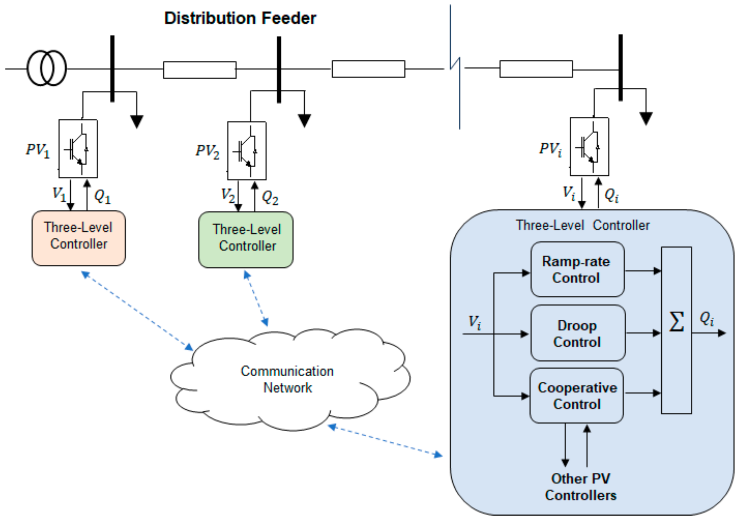
grid-tied inverters. Three-phase inverters might also include the independent control of positive and negative sequence power). This inverter architecture therefore supports microgrids, weak grids, or other grid-management strategies that may arise on disparate networks. The control architecture of a DER inverter is shown in
Figure 14, which includes several recent innovations. It is now mandated in the technical standards that grid-tied inverters should include prescribed functions with respect to the inverter behaviour for voltage and frequency changes at the connection point, also known as PQ response modes, in addition to limits on power output. A detailed description of smart inverter functions for grid management, which are prescribed in the standards, is omitted in this report since it has been well described in [
60]. However, from an interoperability perspective, it is worthwhile considering some emerging areas in inverter control architectures for grid-coupled energy sources. Increasingly, the inverter also interfaces with external devices, for example, a PQ meter at the point of grid coupling, or a load control device.
Advances in fast information processing power and device connectivity, in conjunction with an evolving electricity market architecture, are enabling new areas of innovation in inverter control for customer energy resources. In particular, and in no specific order, the following trends in inverter control can be identified:
Multi-level hierarchical control—The advantage of this approach allows for the independent control of the dynamic response over different timescales, with voltage regulation as one example. This is described further below.
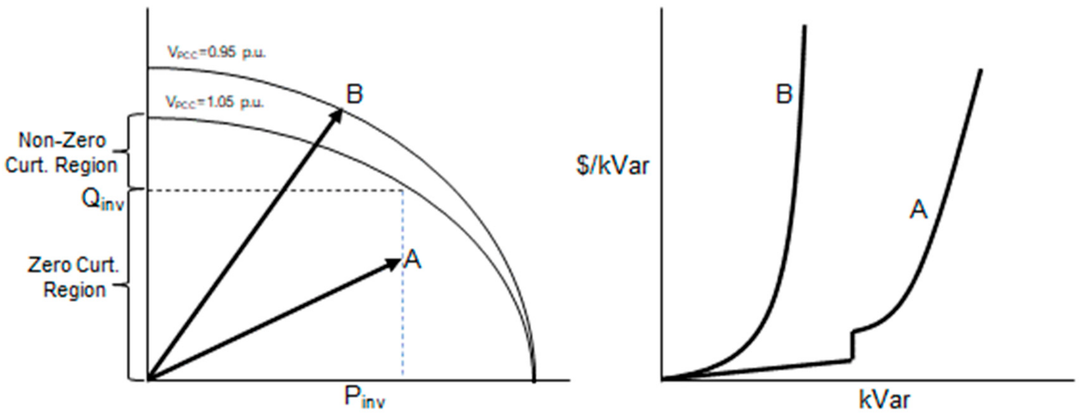
Transactive energy—This mode of operation is based on customer incentives, usually market signals, rather than direct commands, or dispatch instructions. An example of transactive VAr control is provided below.
Machine learning—In principle, if the inverter can access a physical model of itself and its physical environment, then it can synthesise local control strategies which are closer to the optimal. More importantly, the inverter can learn the model from measured data alone and anticipate events so as to take corrective action before they occur. This has particular application in model-based control, such as MPC.
Agent-based cooperative control—This control architecture was described in
Section 2, where the use of MAS design principles can improve the resilience of large-scale interconnected systems, such as the electricity grid. In particular, this is important for CER-CER interoperability and includes, for example, peer-to-peer networking and wireless ad hoc networks. This is more often associated with wireless networks, which can have sparse graph structures.
As an example, a multi-level hierarchical voltage control strategy for PV inverters as described in [
62] is discussed. Referring to
Figure 15, which represents a number of PV systems connected along a feeder, the internal control structure of one inverter is shown in detail. As a method for DER control of voltage, this controller design introduces several innovations, which are superior to the traditional PQ response modes. Firstly, the inverter is able to respond to the rate-of-change in voltage, also known as
ramp-rate control, which improves the dynamic response (decentralised, or local, control of voltage using ramp-rate control is also known as Q/P control, where the reactive power output is a function or real power, whereas voltage droop control is known as Q/V control, where reactive power output is a function of the measured voltage at the connection point). Secondly, if local control action is not sufficient to regulate the voltage within the required range, and there is violation of the limits, then multi-agent cooperative action within the group of inverters is utilised. The salient point is that the inverters reach their own
consensus on what extra voltage control effort is required. A similar approach is utilised in [
18,
95].
The real and reactive power output of all inverters is limited by an
operating envelope, which is a function of the instantaneous output current, voltage, and temperature. For a DER owner, there is an opportunity cost associated with reactive power generation, and therefore, because voltage control is an ancillary activity, it is natural to consider the best utilisation of the inverter for an incremental change in the voltage. The control scheme in
Figure 15 does not manipulate the reactive power Q directly; rather,
utilisation is the controlled parameter, which is defined as the ratio of Q to the maximum available reactive power or Q
MAX.
An alternative approach to DER control known as
transactive energy, while normally associated with energy trading, has also been applied to ancillary service provision or grid management by DERs. There have been customer trials of transactive Volt–VAr control in the USA and Europe [
74,
96]. According to this DER control technique, rather than a command, the customer-owned DER is given an
incentive based on an offer for service from the DNSP. This consists of a set of price/quantity values as a table or curve for the supply of the service, which is communicated to the DER using, for example, IEEE 2030.5, with a subsequent response from the DER for an agreed level of output. The customer receives a credit for the service. It is assumed that the contractual arrangements are previously decided so that the entire transaction is automatic. An example of transactive Volt–VAr control is shown in
Figure 16. For a more detailed theoretical analysis of transactive grid architectures, refer to [
9,
97] (in principle, similar concepts can be applied to Hz-Watt control. The focus of this section has been voltage control due to the fact that, at present, distributors are not
responsible for the frequency control of generators).
Since the amount of renewable energy generation, combined with battery storage, is forecast to well exceed aggregate demand in some jurisdictions, the curtailing of DER output will become an increasingly common event. As such, DER control actions should be driven by customer preferences, consistent with the new market arrangements. From an implementation perspective, several practical issues for this method of DER control can be considered. In particular, it is not obvious over what time horizon the control action should be applied, and secondly, the operating envelope of the inverter is dynamic since it depends on the line voltage and device temperature, as indicated in
Figure 16. As such, the offer curves are also dynamic, and this complicates the inverter’s transactions with the DNSP. These design issues are yet to be resolved.
For the utilisation of DERs for voltage control on feeders, it is also important to consider the effectiveness of P or Q injections for varying the grid voltage. The voltage sensitivity of the connection is defined as the ratio of the change in voltage to an incremental change in the power injected, which can be P, Q, or both. Since the impedance characteristics of feeders, specifically the X/R ratio, impacts the voltage sensitivity to either real or reactive power injection by an inverter, then the DER inverter will have a quantum of minimum kVA output required to effect a unit change in grid voltage. This concept is illustrated in
Figure 17. For example, suppose the desire is for the inverter to effect a 1 V change in grid voltage, using minimal real power output P. The optimal path is shown on the diagram, where the inverter can output purely reactive power at point B, or any combination of P and Q along the path BA, where point A is the minimum kVA required to effect the voltage change. In other words, the maximum voltage improvement is obtained when real and reactive power are injected at this optimal ratio. In principle, if the inverter could
measure the voltage sensitivity, and some inverters do have a mechanism for this, then it can use this information to find the optimal voltage control strategy. The above effect also explains why inappropriate PQ mode settings can result in an undesired voltage fluctuation from intermittent generation such as a PV inverter [
64].
This is the operating principle of a grid utility support system, which is a DNSP-owned battery energy storage system (BESS) for supporting weak grids, SWER, and end-of-line customers in rural areas (a number of these units have been deployed in rural areas of Queensland). During an increase in ΔV (low line voltage), the DER control algorithm initially operates to provide reactive power support only (Q-MODE), up to the rated maximum capability of the inverter. The DER controller then switches to real and reactive power mode exports (PQ-MODE-EXP) and adjusts the power angle at a constant Smax limit towards the line of maximum voltage sensitivity OA as ΔV increases. The voltage sensitivity is determined automatically during a “tuning” phase by injecting real then reactive power and determining the change in voltage in each case. In PQ-MODE-EXP, the controller implements a linearised control law that adjusts θ for charges in ΔV. The batteries discharge in this mode, and when the state of charge (SOC) percentage reaches near zero, the controller switches back to Q-MODE. During a decrease in ΔV (high line voltage), the algorithm initially operates to provide real power support only (P-MODE), up to the rated maximum of the inverter, Pmax, or other pre-determined maximum charge rates, by charging the batteries. The controller then switches to real and reactive power mode exports (PQ-MODE-IMP) and adjusts the power angle θ at a constant Smax limit towards the line of maximum voltage sensitivity OA as ΔV decreases. The battery is charged in these modes. When the SOC reaches near 100%, the controller switches back to Q-MODE.
7. Conclusions
This article has provided a broad review of DER control and management strategies for distribution networks, with a focus on Australian DNSPs. The paper has covered a wide range of topics that include theoretical and practical issues, with a focus on how DNSPs might integrate DER control as a tool in active network management. The article aimed to be forward-looking and so included selected areas of active research and future directions for the technology. The following summary remarks are provided for each topic. DER control concepts and architectures: Emerging DER control architectures will have a distributed rather than centralised control hierarchy. The article has emphasised the importance of interoperability, and issues such as hidden coupling are critical concepts for grid optimisation problems over distributed networks. Interoperability is the fundamental concept which enables highly transactive DER control architectures. Active network management strategies for low-voltage networks: DNSPs are actively investing in solutions which will help to improve the visibility and controllability of their networks, and this includes DER control. These control problems are highly complex and point to several practical issues for DERMS, given the unique characteristics and management philosophies of DNSPs are different, for example, rural compared to urban networks. DERMS platforms should be open, modular, and scalable. The scenario of voltage regulation along a PV-rich distribution feeder was used to illustrate the advantages of both extending and enhancing network models and of closing the feedback loop to the DER, which depends on communication infrastructure and standards. Progress on interoperability and standards: This section gave an overview of the status of developing DER interoperability standards. The hierarchical model of interoperability defines domains, use cases, and feature sets. The challenges in this area are many, including the number and scale of connected devices, consumer electronics, EVs, the cost of compliance, and the risk for vendors, which results in an increasingly complex compliance landscape to navigate, while certification and testing regimes for compliance are still to be fully developed. The key trends in DER inverter design architecture and enhanced functions were described. Active research areas in DER control. This section gave a brief overview of some areas of innovation in DER control, which are the focus of active research and investment. The areas identified included machine learning and adaptive dynamic programming (ADP), distributed model predictive control (D-MPC), multi-agent cooperative control (MAS), the management of power quality problems (PQ Control), and cellular, IOT wireless and satellite communication systems, which included an overview of cybersecurity considerations for DER control. As a concluding remark, the following open problems have been identified for the DER control of distribution networks, which might also be described as DER integration issues which remain to be resolved.
The extension of IEEE 2030.5 function sets, e.g., the control of DER in microgrids.
Peer-to-peer communication including DER to DER, DER meter, DER-uPMU.
The extension of dynamic operating envelopes to controlled loads and EV charge flow scheduling.
Cybersecurity open problems, e.g., the last mile issue for NB-IoT, LPWA devices, and the digital certificates’ lifecycle.
Extended PQ control modes and interoperability requirements for inverter standards, including the further development of transactional PQ control modes.
National certification and end-to-end testing regimes.
Use cases for Next-Gen 5G and 6G cellular wireless and satellite technology in DER control are being investigated, and the extent of the possible application of these innovations is still to be understood.
Other than voltage regulation, a promising application area for DER control in distribution networks are remedial action schemes and network self-healing. Australian DNSPs are transitioning to automated fault location, isolation and restoration (FLISR) processes, though the actual scale of deployments is quite limited. It has already been demonstrated that DERs, in particular energy storage, can be utilised for both emergency demand response [
67] and during grid restoration [
50] or black-start scenarios. The Australian electricity grid covers an extremely large geographic area and range of climatic conditions and so is particularly vulnerable to natural disasters such as bushfires and severe storms. There are several challenges for the DNSP with respect to implementation FLISR for regional and rural distribution networks: (i) due to the levels of PV penetration, it is possible for bi-directional power flow which impacts feeder protection devices, (ii) as DERs are normally non-utility assets, an agreement is required to engage non-utility assets for remedial action, and (iii) rural networks have poor communication coverage with no telemetry, so much of the network is not visible from the control room. The deployment of an adequate communication infrastructure which might facilitate centralised control for FLISR is cost-prohibitive for most rural DNSPs. This is a natural application area for agent-based DER control architectures that are decentralised and use peer-to-peer communications, which was described in
Section 2. The advantage of decentralised architectures is their scalability, which is an essential requirement for sparse networks and has been the focus of several DNSP pilot projects [
50]. The operational objective of a redial action scheme is to maximise the number of restored customers during a post-fault scenario in the shortest timeframe given the network constraints. This is inherently an optimisation problem which can be solved using distributed coordination algorithms as described in
Section 3. This involves the post-fault reconfiguration of protection settings using distributed coordination. In a practical sense, the proposed design schemes for utilising DER control for remedial action need to have the following common features: (i) devices participating in the restoration need to be topology-aware and have situational awareness of the local network state, (ii) non-utility assets such as DERs should be incentivised to participate using transactive energy signals, and (iii) the forming and control of microgrids may be necessary. It has already been demonstrated that microgrids and EVs using V2G technology are able to restore power to customers during natural disasters. This will be an important future application area for DER control for DNSPs which will enhance the resilience of electrical distribution networks [
126].
It was seen that for DER interoperability in the control domain, there should be a natural correspondence between the function sets and domains of the DER protocol’s information model and the optimisation–decomposition of the power system control problem. As the grid architecture inevitably transitions towards a more transactive DER control framework, a synthesis is needed which can reconcile classical and transactional power system control. In the Australian context, work programs are focused on DER participation in the National Energy Market (NEM) beyond demand response to include other use cases, such as EV participation, the governance of DER technical standards, and the scheduling mechanisms for medium- and small-scale DERs. Flexible DER connections based on dynamic operating envelopes (DOEs) are now widely adopted, though they will need to be extended and enhanced to support a transactive marketplace for DER services (the Battery Storage and Grid Integration Program at the Australian National University (ANU) are trialling shaped operating envelopes (SOEs) in 1000 household-based batteries as an enhancement of DOEs which factors customer preferences).
