1. Introduction
Single-phase furnace transformers are almost always used in the power supply system of high-power ore-thermal plants to reduce the line voltage from 6–10 kV to 150–320 V, regardless of the ore furnace type. The electrical energy from a furnace transformer to furnace electrodes [
1,
2,
3,
4,
5] is usually transmitted through a high-current system. A high-current system consists of compensators, a busbar assembly, flexible couplings, as well as a system of shoes, a contact clamp, and electrodes [
3,
4,
5,
6]. A busbar assembly is the longest and most expensive part of a high-current system. Since operating currents in a high-current system can reach 35–150 kA [
7,
8], the secondary winding of a furnace transformer is split, and the number of pairs of tube buses in the busbar assembly of a high-current system is equal to the number of these splits. Therefore, a key electrical fault in a furnace transformer is turn-to-turn faults (TF) [
9,
10,
11,
12,
13,
14], and flexible coupling breaks and arc faults (AFs) in splitting circuits [
15] predominate in its high-current system.
Due to the design features of single-phase transformers in ore furnaces, overcurrent protections based on current transformers (CTs) are currently used to protect a transformer from SC in the power cable, and the primary winding and gas protection is commonly used against TFs [
12]. However, such an overcurrent protection is near-insensitive to TF, and the response time of gas protection can be long because it strongly depends on the oil temperature and the number of closed turns. In addition, gas protection is inapplicable to dry-type transformers. Therefore, a TF is accompanied by significant damage to the primary circuit; sometimes, the transformer completely fails.
To protect against an AF between the tube buses of a busbar assembly, all the tube buses are electrically insulated [
14]. However, a high-current system usually operates under a high temperature and high content of coal and abrasive dust in the air in ore-thermal plants. Under these conditions, the insulation of tube buses in the busbar assembly of a high-current system quickly fails, conductive coal dust bridges appear between them, and, finally, a short circuit can occur in a pair of tube buses, and an electric arc can form. This arc can completely damage an expensive busbar assembly in a fraction of a second under operating currents in a furnace [
3,
14].
Flexible coupling breaks in the splitting circuits of a high-current system result in zero current in the damaged pair of tube buses and a significant increase in the current in the remaining pairs of tube buses. This can lead to overheating and failure of the tube buses. However, there are no protection systems against this fault type, and they can sometimes be indirectly detected from instrument readings.
To detect a TF in the busbar assembly of a furnace, longitudinal differential protection with CTs can be used [
12,
16,
17]. However, it requires a CT with a rated current of 10–30 kA to be mounted in each split of each phase of a high-current system. Such CTs are very expensive and large, while the space between the axes of the tube buses does not exceed 100–150 mm. Therefore, the use of CTs in differential protection is of little promise.
Instead of CTs, cheaper Rogowski coils can be used in a high-current system for these purposes [
18,
19,
20]. They are fixed only on tube buses, with a forward current in a busbar assembly. In this case, all the Rogowski coils in one busbar assembly are series-aiding. However, manufacturing and mounting Rogowski coils on the tube buses of a busbar assembly is a difficult engineering task because air gaps between the tube buses are 20–40 mm. In addition, the electromotive force (EMF) of each Rogowski coil and the transfer of electrical signals from these coils are strongly affected by the magnetic fields produced by the currents in the other tube buses of the high-current system. Thus, it is challenging to implement AF protection in the busbar assembly of the high-current system of an ore furnace with the use of Rogowski coils.
A new and little-studied direction in relay protection is the use of magnetic current transformers (MCTs) in the electrical fault protections of single-phase transformers in ore furnaces with a high-current system [
12,
13]. An MCT is usually made as a textolite carrier bar with a winding in the form of several in series-aiding multi-turn coils. The MCT operation is based on measuring the magnetic field of the transformer windings. To do this, an MCT is fixed to transformer elements inside the tank in a certain way.
A device for the relay protection of the busbar assembly of the high-current system of ore furnaces against arc faults [
21] based on MCTs is quite effective. The principle of its operation consists of measuring a stray magnetic field at an arbitrary point on the busbar assembly. However, this protection is incapable of responding to faults in the primary winding of the transformer and breaks in the tube bus circuit in the high-current system.
There is reason to believe that MCT protection sensitivity depends on many factors, including the number of MCTs and their sizes, the number of coils in their windings, and the arrangement of the MCTs relative to the windings of the transformer.
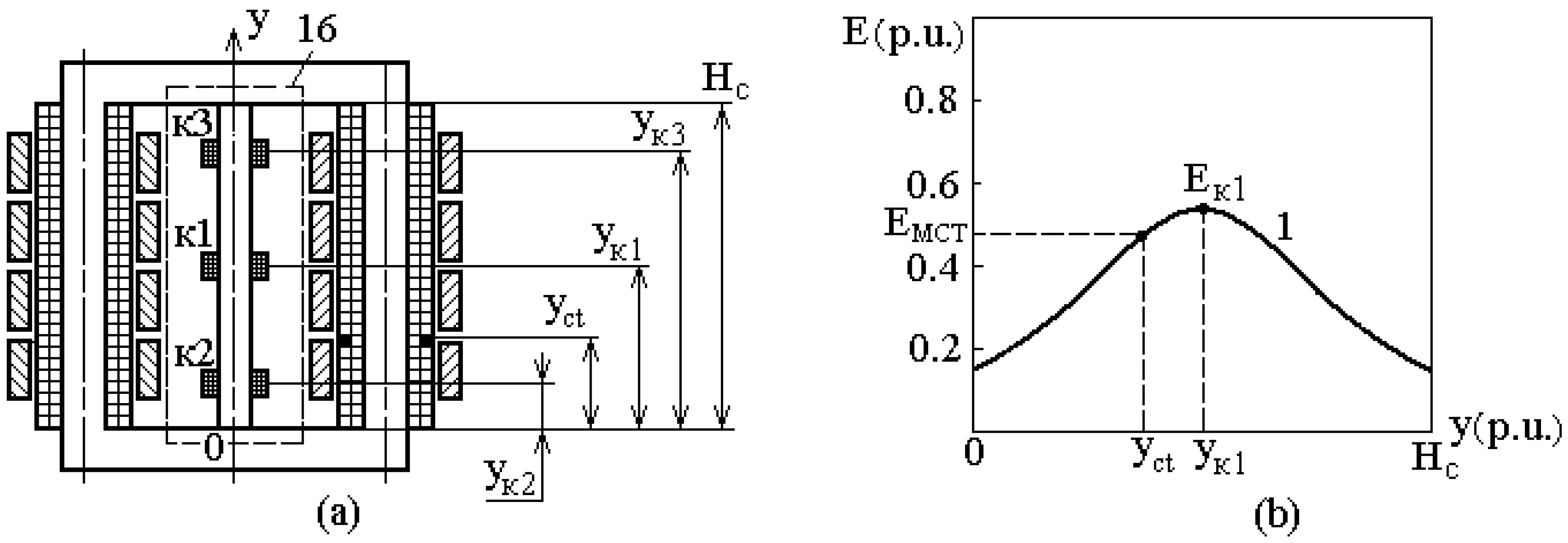
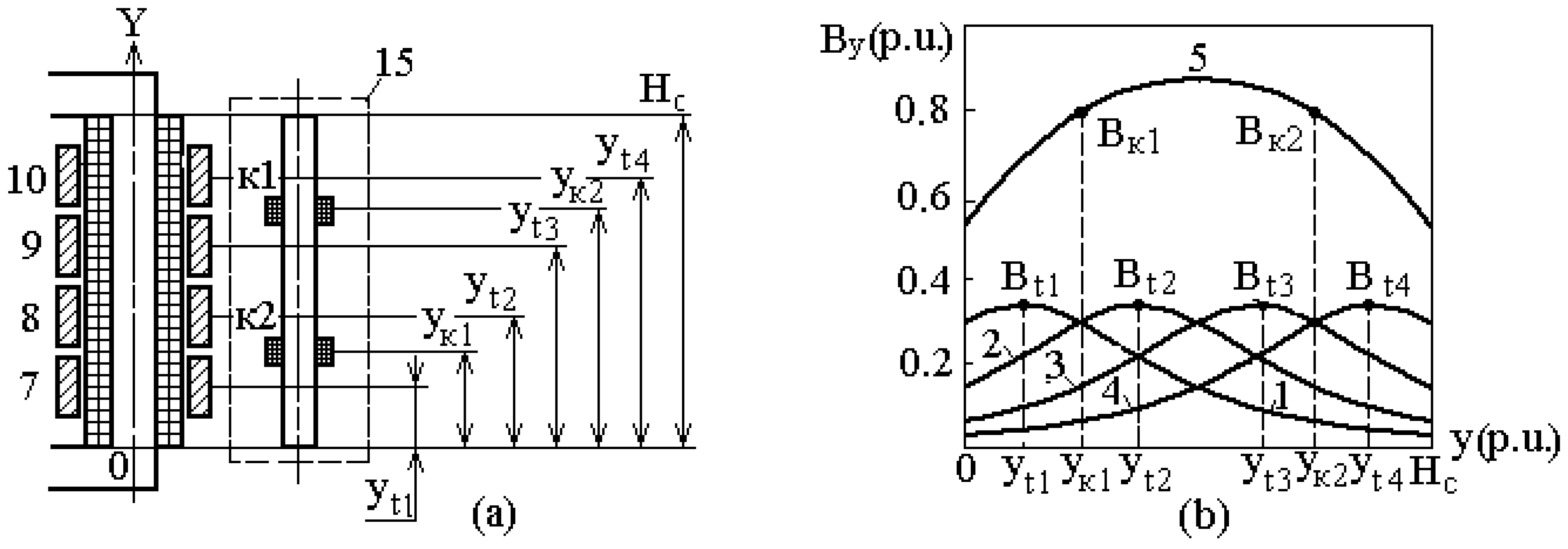
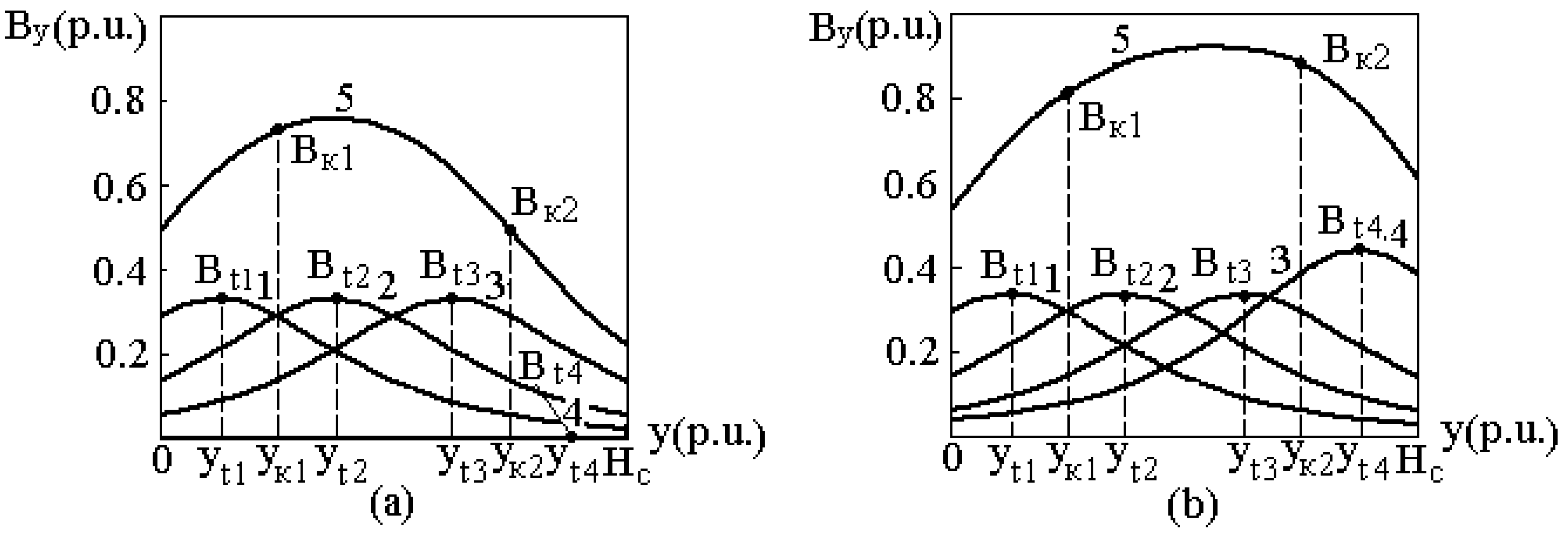
In this work, we suggest the following procedure for constructing electrical fault protection for a single-phase transformer in ore furnaces with a high-current system based on MCTs. First, the technique and device for protecting a transformer and a high-current system are described. Then, from the analysis of the EMF values of the winding coils of an MCT, depending on their location relative to the windings of the transformer operating under different modes [
22], their number and positions of windings in the MCT are determined. Based on the results, a protection circuit is designed; the protection response threshold is calculated, the protection operation is described, and the results of the experiment are given.
3. Results
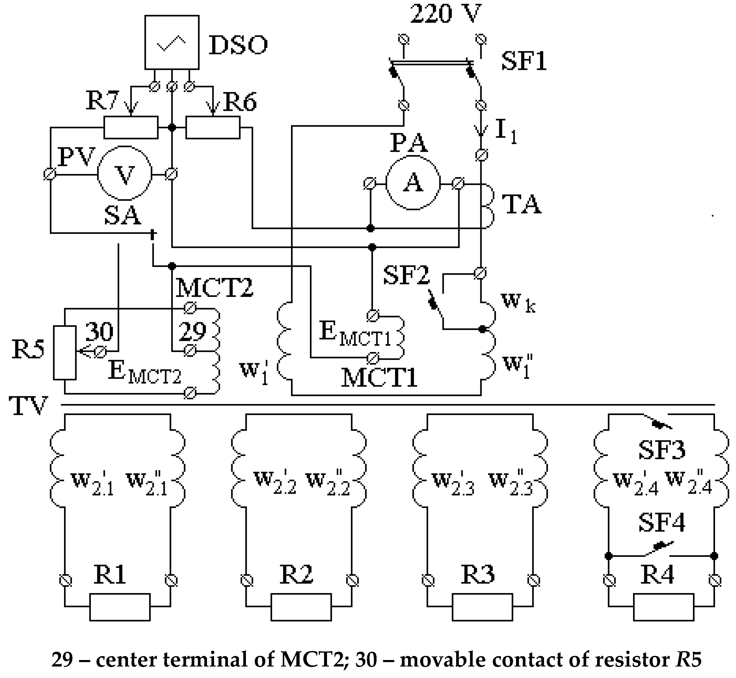
Full-fledged experimental studies on verifying the reliability of the above-discussed theory ground the design of the protection of high-current transformers in ore furnaces against faults with a real transformer during the operation of an ore furnace. Therefore, we performed a laboratory experiment with a TT-6 transformer with 6-kVA of power. The circuit of the electrical setup is shown in
Figure 7.
As can be seen from
Figure 7, the primary winding of the transformer of the experimental setup is connected to a single-phase 220-V alternating current network through AP-50 breaker SF1. The winding consists of two in series-aiding parts with
and
turns, which are placed on the left and right legs of the core. The current in this winding is measured by a type E59 ammeter (PA) with an accuracy class of 0.5, which is connected to the network through a current transformer type I54/1 (TA) with an accuracy class of 0.2. The current in the primary winding is recorded by the first channel of a two-channel oscilloscope (DSO). This oscilloscope is based on a personal computer with Elena-2014 software and enables the recording of two measured signals depending on time. To record the current, the first input of the oscilloscope is connected to the terminals of the ammeter PA, which ensures the galvanic isolation of the oscilloscope input and the supply network. The voltage at the DSO input is controlled by a high-resistance resistor (R6). The network voltage is measured by a UNI-T UT101 voltmeter (PV) (Dongguan, Chengdu and Changzhou, China). During the experiments, shorted turns in the primary winding
were performed as an individual winding wound on a transformer coil. They are closed by an automatic type AP-50 breaker.
The secondary winding is made in the form of four splits. In this case, splitting parts are located on the left and core legs ( and , respectively). During assembly, these parts of the secondary winding are in series-aiding connected. The transformer load connected to them is represented by resistors R1–R4. The breaking modes in a pair of tube buses and the occurrence of a short circuit in them are simulated with the use of automatic AE 2016-10HY3 (Novosibirsk, Russia) breakers SF3 and SF4.
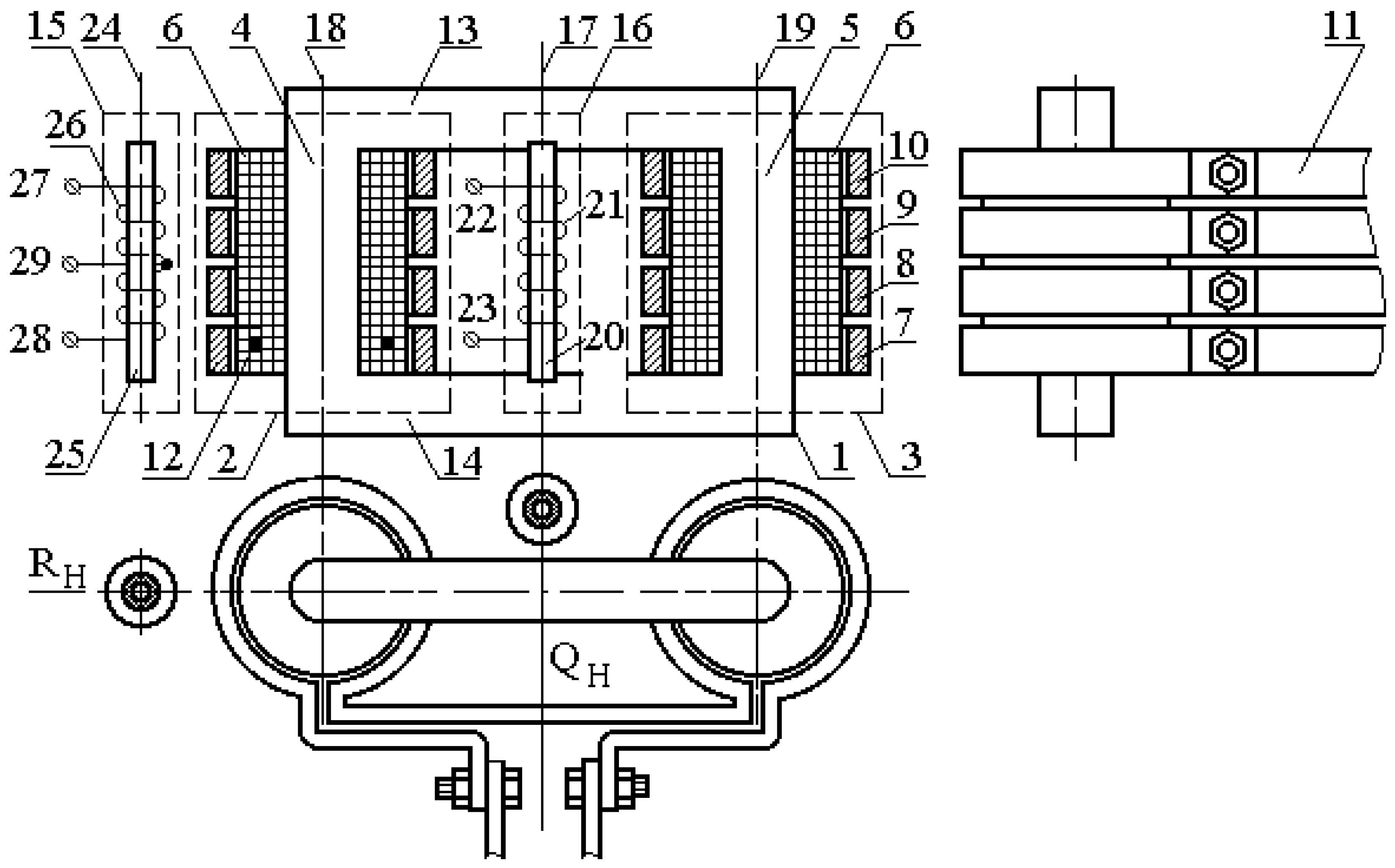
The MCT1 16 protection winding was made in the form of a coil from an intermediate RP-8 relay [
27]. This coil includes 12,500 turns and is fixed to the transformer using a PCB strip, as shown in
Figure 1. The MCT1 voltage
UMCT1 is recorded by the second channel of a DSO. To do this, the terminals of the MCT1 coil are connected to the second input of the oscilloscope through switch SA.
The MCT2 15 protection winding includes two series-aiding coils from an intermediate RP-8 relay [
27]. These coils are fixed to the transformer using a PCB strip, as shown in
Figure 1. The distance between them is approximately 0.6
Hc. The terminals of the MCT2 coils connected to the resistor form a measuring bridge, the output of which is connected to the second input of the oscilloscope through a switch.
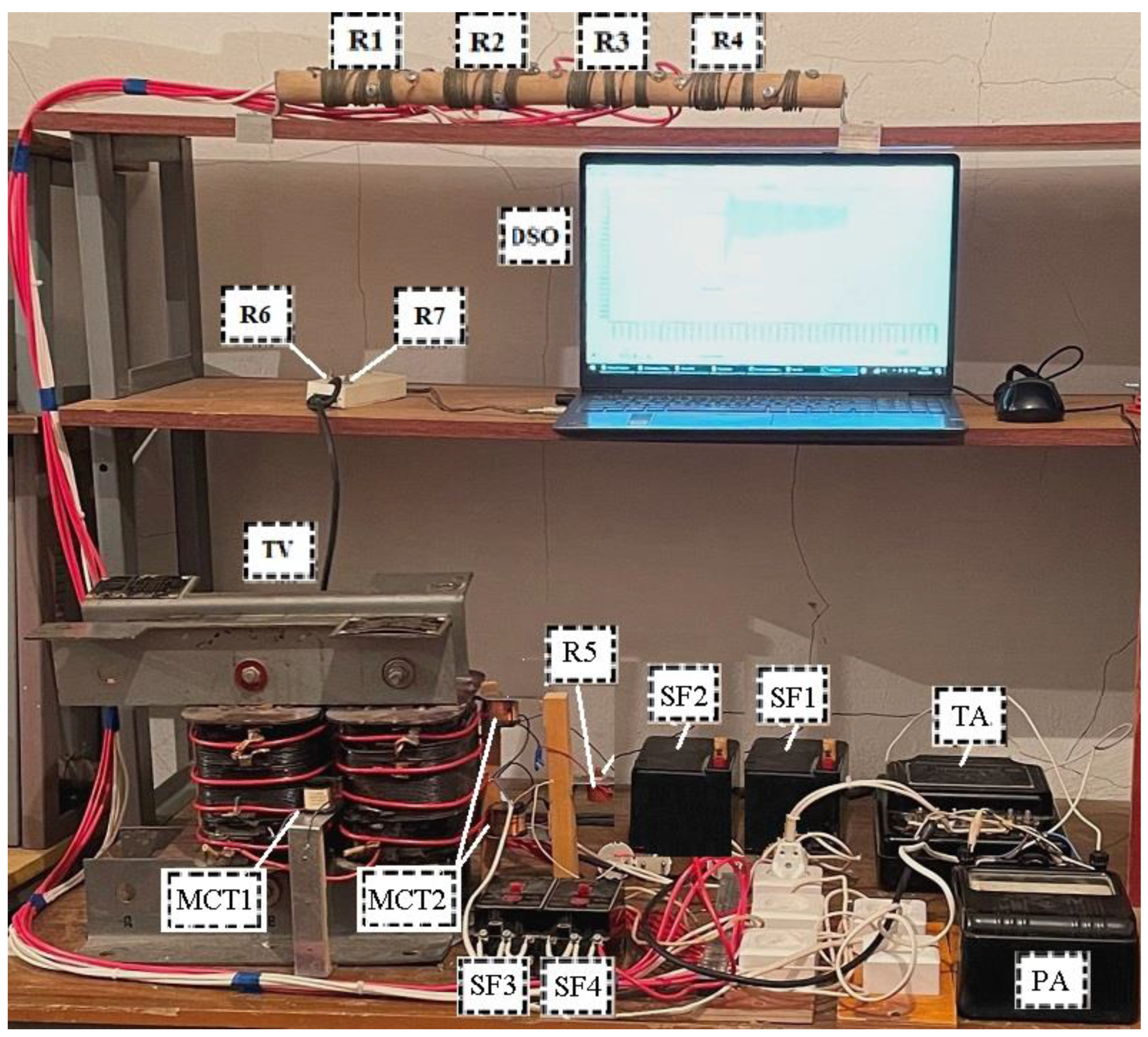
The experimental setup is shown in
Figure 8. Here, TV is the experimental TT-6 transformer; SF1 and SF2 are the automatic AP50 breakers; SF3 and SF4 are the automatic AE 2016-10HY3 breakers; TA is the measuring I54/1 current transformer; PA is the E59 ammeter; DSO is the laptop-based digital oscilloscope with Elena-2014 software;
R5–
R7 are the high-resistance variable resistors; MCT1 and MCT2 are the magnetic current transformers; and
R1–
R4 are the load resistance. The high-current system and arc resistances are simulated by resistances
R1–
R4. In real conditions, arc resistances are not constant; however, by replacing them with
R1–
R4, we correctly simulated the operation of a high-current TT-6 transformer.
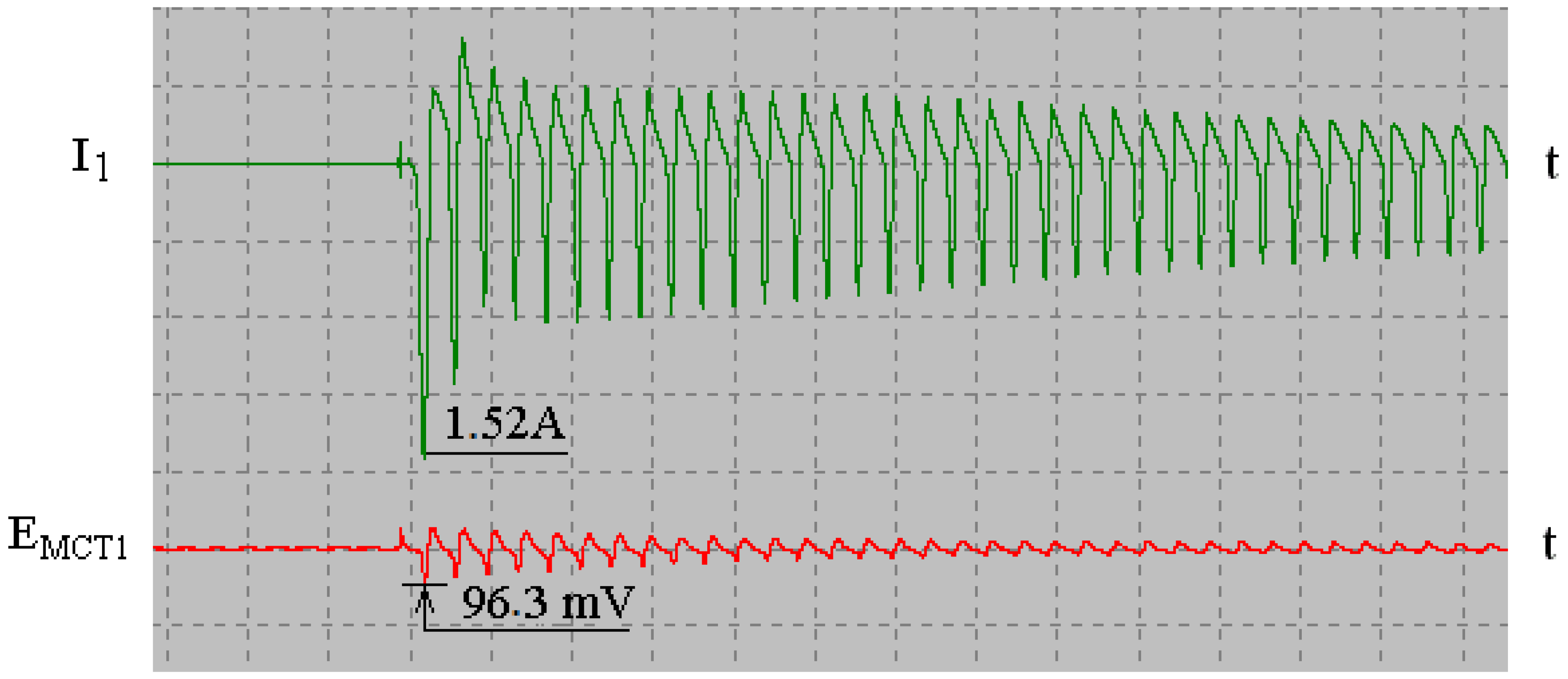
At ore-thermal plants, a furnace transformer is switched on in idle mode.
Figure 9 shows the oscillograms of the current
I1 in the primary winding of the transformer and the EMF
EMCT1 of MCT 16 recorded during the experiment when the TT-6 transformer was energized in idle mode.
These oscillograms show the maximum current I1 to be 1.52 A and the maximum EMF EMCT1 to reach 96.3 mV. Only these values were used when designing the protection to determine its response threshold.
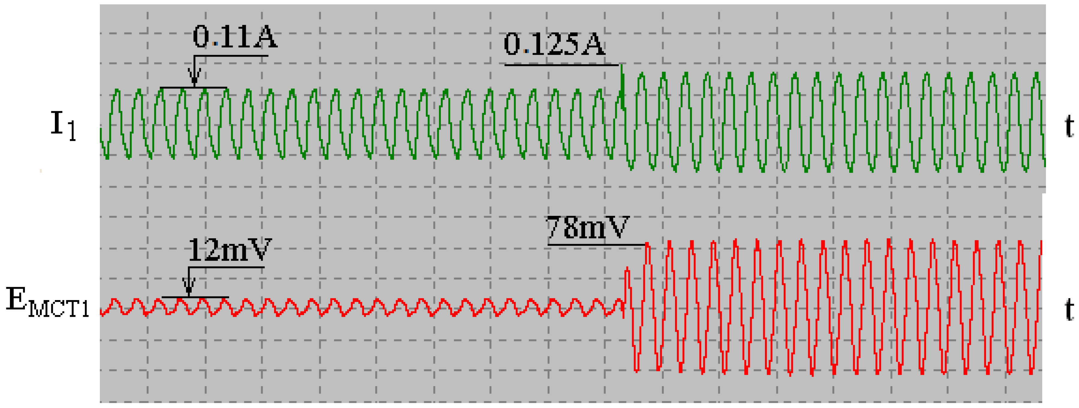
The experimental results are shown in
Figure 10 in the form of oscillograms of the current
I1 in the primary winding of the transformer and EMF
EMCT1 of MCT 16 when closing one turn in the primary winding in idle mode.
These oscillograms show that the imbalance in the EMF of MCT 16, Eib1 = 12 mV in this mode. If only one turn of 292 turns to the primary winding is closed, then, the EMF increases to 78 mV. This confirms the high sensitivity of the protection to turn-to-turn faults.
The sensitivity of this protection can be estimated, taking into account
Figure 9 and
Figure 10, as follows. First, the dependence
EMCT = f(
wct) experimentally derived in idle mode is plotted, as shown in
Figure 11. Then, the protection operation threshold is calculated, taking into account the maximal imbalance in EMF
Eib1 for the MCT used. Since the maximal
Eib1 = 0.0963 V when energizing the transformer (see
Figure 9), the MCT EMF, which triggers the protection operation, is as follows:
If a horizontal line is drawn through point
Eact1 on the
EMCT axis in
Figure 11, the number of turns under which the protection operates can be found from the point of intersection of this line with the dependence
EMCT(
wct) on the axis
wct. Since the number of closed turns can only be an integer, according to
Figure 11, the protection operates when three turns are closed.
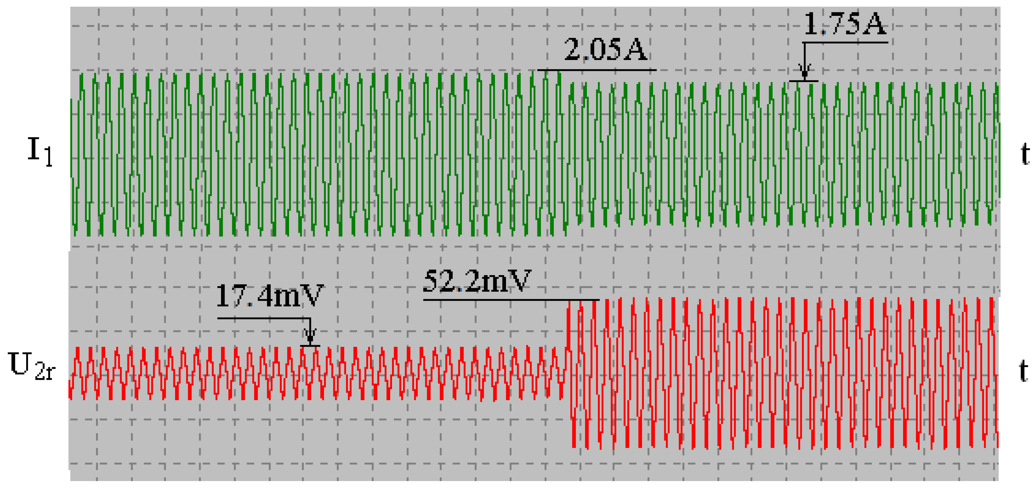
The furnace transformer energizing is accompanied by the appearance of voltage
U2r, determined by the imbalance in values at terminals 29 and 30 and relay 32. The oscillograms of the current I
1 in the primary winding of the transformer and the voltage
U2r of MTT 16 experimentally recorded when energizing the TT-6 transformer in idle mode are shown in
Figure 12. These oscillograms show that the maximal imbalance in voltage
U2r = 17.5 mV at a magnetizing inrush current of 1.5 A. In this case, the voltage
Uact2 at which the protection of the high-current system should operate is as follows:
The experimental oscillograms of the current
I1 in the primary winding of the transformer and the voltage
U2r of MCT 15 recorded with breakers
and
during a break and a short circuit in a pair of tube buses are shown in
Figure 13 and
Figure 14. They show that the voltage
U2r of MTT 15 is equal to 52.5 and 270 mV in case of a break and a short circuit in a pair of tube buses, respectively. These values are significantly higher than the voltage
Uact2 at which the protection of a high-current system should operate.
Thus, the laboratory experiments confirmed that the technique suggested for designing the protection of an ore furnace transformer against turn-to-turn faults and its high-current system against electric faults ensures the high sensitivity of the protection to these faults.
4. Discussion
The main electrical faults in a single-phase transformer in ore furnaces with a high-current system are turn-to-turn faults in the primary winding of the transformer and breaks in flexible couplings and arc faults in the splitting circuits of the high-current system. This is due to the fact that the secondary winding of a furnace transformer is made of several splits isolated from each other; the high-current system has flexible couplings, and its busbar assembly is made from tube bus pairs, the number of which is equal to the number of splits in the furnace transformer.
Due to the design of an ore furnace transformer with a high-current system, overcurrent and gas protections are used in these transformers against short circuits and turn-to-turn faults; the electrical insulation of tube buses in the form of several layers of sticky fiberglass is used to protect against arc faults.
The choice of MCT for constructing a protection system for a transformer and high-current system is due to the following reasons. Overcurrent protection is insufficiently sensitive to turn-to-turn faults. Gas protection can have a long response time. The sticky fiberglass insulation of tube buses is destroyed by abrasive dust contained in the ambient air. No protection against breaks in flexible couplings in a high-current system is usually used, which might be because of the absence of sufficiently simple and cheap ways to solve this problem. The design of differential current protection based on current transformers is a complex and expensive engineering problem due to the need of a large number of CTs suitable for 10–20-kA networks, their high cost, and the difficulty of fixing CTs on tube buses with small air gaps between them in a busbar assembly.
An analysis of the distribution of magnetic fields of the coils of a single-phase transformer operating in an arbitrary load mode has shown these magnetic fields to be symmetrical about the plane that is perpendicular to the yokes of the magnetic circuit and passes through their center. Based on this, a technique is suggested for protecting a single-phase transformer from turn-to-turn faults, within which the stray magnetic field of this transformer is measured in this plane and compared to a reference value.
A similar analysis of the distribution of the magnetic fields of the coils of a single-phase transformer operating in an arbitrary load mode has shown that these magnetic fields are symmetrical about the plane that is perpendicular to the cores and passes through their center. Based on this, a technique is suggested for protecting a high-current system from arc faults between the tube buses of a busbar assembly and breaks in the circuit of one of its splits.
Using these techniques, a simple and cheap MCT-based electrical fault protection system has been designed for a single-phase high-current transformer in ore furnaces. The system consists of two functional units.
The first functional unit protects a single-phase transformer from turn-to-turn faults. It is based on one MCT located between the coils of the transformer. To implement it, the choice of MCT position is justified, the design of this MCT and the electrical circuit of this functional unit are suggested, and its response threshold is calculated. This unit is highly sensitive to turn-to-turn faults in the transformer windings and is capable of tripping it if only a few turns are closed. The high sensitivity of this functional block to turn-to-turn faults in the primary winding of the transformer is confirmed by experimental results.
The second functional unit is also based on one MCT. It detects arc faults between the tube buses of a busbar assembly and breaks in the circuit of one of the splits in a high-current system. To implement this functional unit, the choice of MCT position is justified, the design of this MCT and the electrical circuit of this functional unit are suggested, and its response threshold is calculated. This functional unit enables one to quickly turn off the transformer in the event of an arc fault, to identify and disconnect a damaged pair of tube buses from the circuit, and to successfully complete the smelting of a ferroalloy in an ore-thermal furnace, which undoubtedly significantly reduces the downtime of the furnace and the cost of repair.
