1. Introduction
The transformer is crucial primary equipment in the power system, and its stable operation is closely related to the reliability of the power grid. Typically, failures in power transformers can be classified into insulation failures, mechanical failures, and conductor failures. According to statistical results, insulation failures account for the highest proportion of transformer failures among these three categories [
1]. Partial discharge (PD) refers to the phenomenon where a localized discharge occurs in the insulation part of electrical equipment under the action of a strong enough electric field. This often occurs at defects. such as cracks, bubbles, and metallic impurities within the insulation medium [
2]. PD is accompanied by the generation of a series of gases and chemicals, as well as local temperature rises and insulation corrosion, which can accelerate insulation deterioration at the defects, and even lead to severe damage to the entire electrical equipment due to a vicious cycle. Partial discharge testing can effectively assess the degree of insulation aging and evaluate the health status of transformers [
3]. In large-capacity transformers with compact internal structures, partial discharge situations are more complex, with discharge energy, discharge types, discharge locations, and the number of discharges all closely related to the degree of insulation degradation [
4]. Therefore, timely detection, identification, and accurate localization of complex partial discharges that occur during actual operation and production are of great significance for production maintenance, troubleshooting, reducing power outages, and shortening maintenance cycles.
For power transformers with complex structures, the probability of partial discharge occurring in the windings is the highest, and the associated hazards are the most significant. Equipment maintenance personnel detected two consecutive discharge pulse signals through the pulse current method but were unable to locate them accurately. Although traditional ultrasonic detection methods can be used for localization, they are greatly affected by environmental interference and are unable to detect two accurate discharge waveforms. The missed detection of PD sources can result in ineffective maintenance, and repeated repairs can increase transformer maintenance costs. In summary, the multi-point detection and localization of partial discharge within transformer windings are crucial for the safe operation of power systems and the optimization of maintenance plans. The localization of dual partial discharge sources can help improve the accuracy and efficiency of fault detection. Traditional fault detection methods often rely on manual inspections and empirical judgments, which are not only time-consuming and labor-intensive but also susceptible to human factors. However, through research on dual partial discharge source localization technology, automatic identification and localization of fault points can be achieved, significantly improving the accuracy and efficiency of fault detection.
Partial discharge is accompanied by electromagnetic pulses, sound, light, and other phenomena, which can be used to characterize the occurrence and intensity of partial discharge. Through processing and analysis of relevant algorithms, information, such as the location and magnitude of partial discharge, can be determined. Reference [
5] employs the optical signal generated by partial discharge for online monitoring of power equipment with partial discharge. Reference [
6] utilizes ultrasonic methods to inspect gas-insulated switchgear and implements the detection of weak partial discharge signals through noise reduction algorithms. Currently, transformer partial discharge localization methods mainly focus on electrical methods, ultra-high-frequency methods, and acoustic methods. As an effective and accurate localization methodology, acoustic methods have been widely used in industry [
7].
The general acoustic localization method involves the use of piezoelectric transducers (PZTs) that are magnetically attached to the metal shell of the transformer tank [
8]. The position of the partial discharge source is inferred by utilizing the time difference between the arrival of ultrasonic signals generated by partial discharge at different piezoelectric transducers [
4,
9,
10,
11,
12,
13]. However, this method has several drawbacks. Firstly, ultrasonic waves undergo attenuation and distortion after refraction and reflection through windings and tank walls. Secondly, transformers operate in environments with numerous interference signals, resulting in low signal-to-noise ratios (SNR) for the signals measured by the sensors and large localization errors. Especially for partial discharge signals occurring within transformer windings, even in ideal environments, PZT can experience difficulty capturing this type of discharge signal [
1,
14,
15,
16,
17]. With the increasing application of optical technology in partial discharge detection, fiber-optic ultrasonic sensors have emerged as a novel method for detecting partial discharges. Reference [
18] fabricated a single Fabry–Perot (F–P) sensor and detected the partial discharge waveforms inside transformers, but further applied research was not conducted. Reference [
19] arranged F–P sensors in a square array and installed them outside the transformer windings, achieving localization of a single partial discharge source in the oil and on the surface of the outer windings. However, the issue of localizing dual partial discharge sources occurring within the high and low voltage windings was not addressed.
To address the issue of localizing dual partial discharge sources within transformer windings, this paper proposes the deployment of a regular tetrahedron structured F–P sensor array above the oil gallery between the high and low voltage windings of the transformer, with adjacent arrays arranged at 90° intervals. Utilizing the PD positioning system established, in combination with the proposed cross-localization algorithm based on the MUSIC direction-finding principle, only four sensor arrays are required to localize dual partial discharge sources in both the high and low voltage windings of the transformer. This localization system was tested in a 35 kV single-phase transformer, with experiments conducted separately in the high and low voltage windings. The results demonstrate that the localization error is within 18 cm, indicating high positioning accuracy. This method provides a novel approach and solution for locating dual partial discharge sources within transformer windings.
2. F–P Optical Fiber Sensor Array
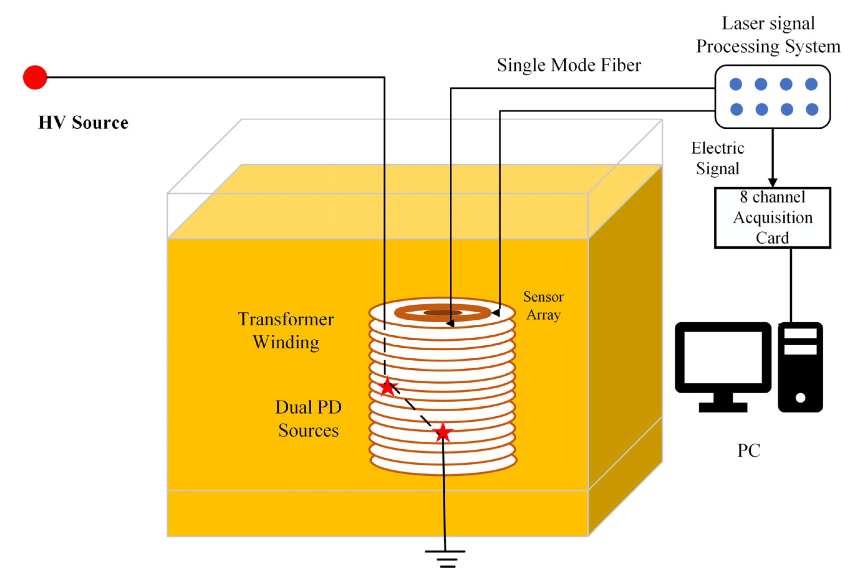
The F–P fiber optic sensor is composed of single mode fiber, silica tube and silica diaphragm. The end face of the fiber and the silica diaphragm constitute two reflecting surfaces of the F–P interference cavity. The schematic diagram of the F–P optical fiber ultrasonic detection system is shown in
Figure 1.
The laser source produces a light, which is divided into eight laser signals through a beam splitter. Each optical signal reaches the sensor probe through an optical path. At the interface between air and glass at the end of the fiber end face, approximately 4% of the light is first reflected back into the fiber, while the remaining 96% of the light passes through the air in the F–P cavity and undergoes a second reflection on the inner surface of the silicon diaphragm [
20]. By adjusting the reflectivity of the silicon diaphragm, approximately 4% of the light can be reflected back into the fiber for the second time. These two reflected beams return along the same fiber, causing interference. The expression for the intensity of the interference light is as follows:
I0(λ) represents the incident light intensity; λ is the wavelength of the light source; R1 is the reflectivity of the fiber end face; R2 is the reflectivity of the inner surface of the silica diaphragm; φ is the optical path difference between the two reflecting surfaces. φ = 4πl/λ, l represents the length of the F–P cavity. It is evident from Equation (1) that, after interference, the intensity of the light reflected back into the fiber only depends on the length of the F–P cavity. Ultrasonic signals generated by partial discharges cause vibrations in the silica diaphragm of the sensor probe, thereby affecting the length of the F–P cavity and producing a fringe interference phenomenon. By detecting the intensity of the interfered light, converting it into an electrical signal, and further amplifying it through a photodetector, the ultrasonic signal can be converted into a pulsed electrical signal. Laser light serves as the intermediate medium for the exchange of these two types of signals, therefore this detection system does not produce electromagnetic interference to the detection equipment. Coupled with the compactness of the sensor probe, it can be flexibly arranged inside the transformer.
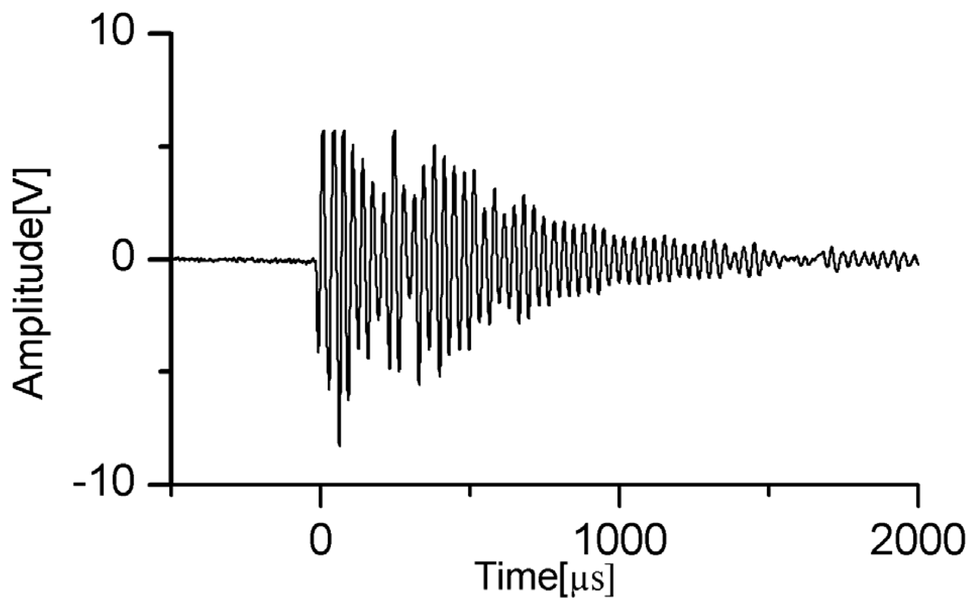
The frequency range of ultrasonic signals generated by partial discharges in transformer oil is between 20–2000 kHz. Through studying the impact of diaphragm thickness and diameter on the central frequency of the sensor, in order to obtain a good signal-to-noise ratio, the final design of the sensor probe has a central frequency of 30 kHz. At a distance of 2 m from the PD source, the sensor can detect a minimum discharge capacity of 100 pC. The output waveform corresponding to the ultrasonic signal from dual partial discharge sources measured by a single sensor is shown in
Figure 2.
As can be seen from the waveform diagram, the designed sensor can accurately distinguish the discharge waveforms from two partial discharge sources. Based on verifying the performance of a single F–P fiber-optic sensor, this paper also designs a sensor array for partial discharge localization. According to the phased array theory, when designing the array structure, in order to avoid grating lobes, the array element spacing
d should satisfy the condition that
d ≤
λ/2, where
λ represents the wavelength of the target to be measured. Under the condition of a fixed number of array elements, it is desired that the array has as large an aperture as possible, namely,
d =
λ/2. In our research, the propagation speed of ultrasonic waves is 1420 m/s, and the central frequency is 30 kHz, so the
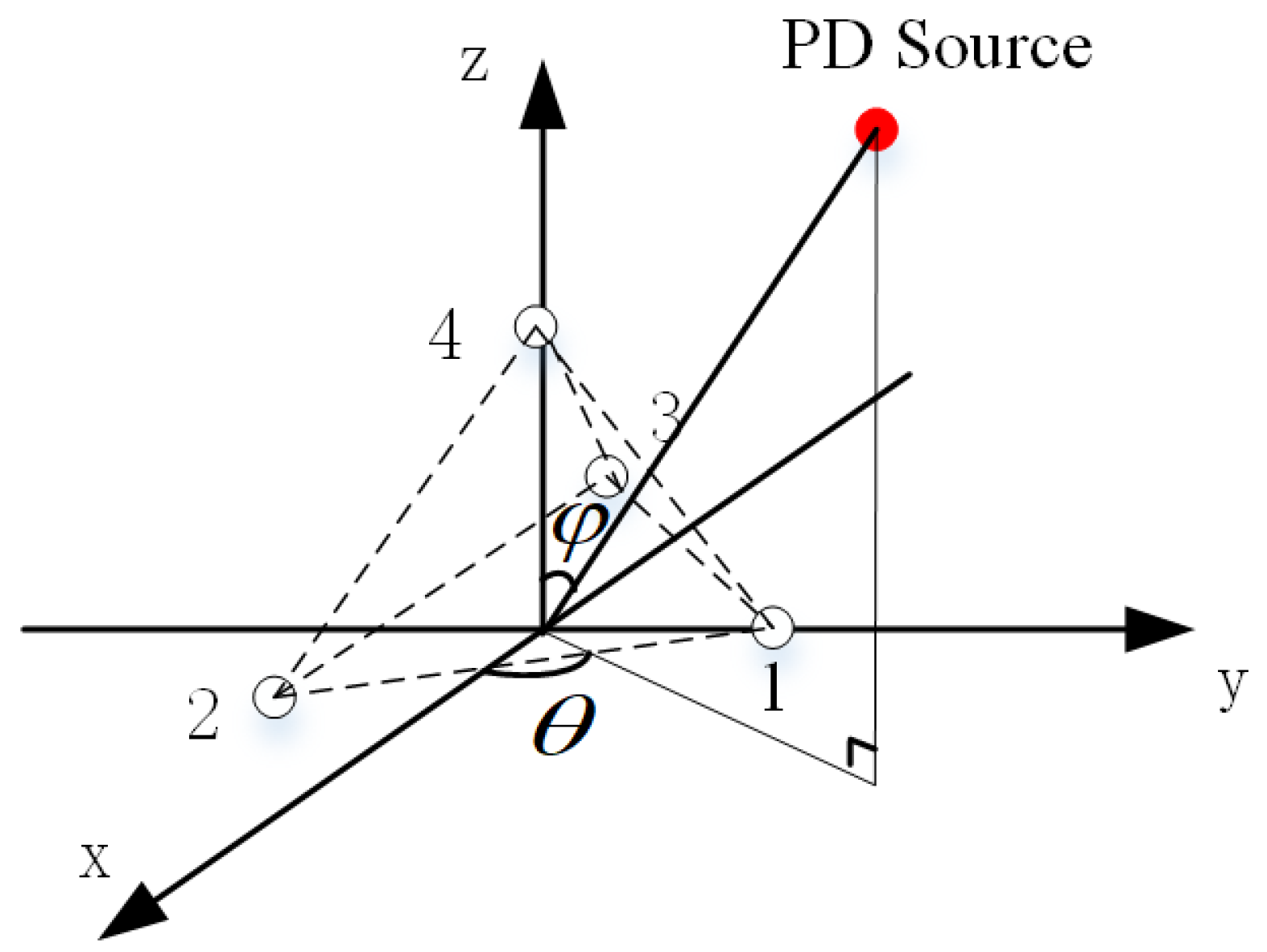
λ ≈ 4.73 cm. Additionally, to ensure the consistency of ultrasonic signals received by each array element and prevent significant waveform differences among the signals from different channels, through multiple experimental results, the spacing between adjacent sensor elements was set to 20 mm, and a regular tetrahedron structure is adopted. The array structure is shown in
Figure 3, where
θ and
φ represent the azimuth angle and pitch angle, respectively. The establishment of the 3D rectangular coordinate system is shown in
Figure 3, and all subsequent discussions in this paper are based on this.
3. Dual Partial Discharge Localization Algorithm
The MUSIC algorithm is a high-resolution spectral estimation method used for signal processing and array processing. Based on the orthogonality principle of signal subspace and noise subspace, it determines the direction of the signal by searching for the peak of the spatial spectrum [
21,
22,
23]. It is particularly suitable for parameter estimation of multi-source signals in noisy environments. However, there are some difficulties in applying the MUSIC algorithm to partial discharge ultrasonic detection. Firstly, the ultrasonic signal generated by partial discharge is a broadband signal, which contains components of different frequencies within a certain range. In addition, the traditional piezoelectric transducers generally has a bandwidth of 30–150 kHz, and the collected ultrasonic signal is also a broadband signal. For the MUSIC algorithm, the signal subspaces of broadband signals at different frequencies are different, which is not suitable for direct directional measurement of traditional piezoelectric transducers. However, the F–P optical fiber sensor designed in this paper has a central frequency and peak sensitivity at around 30 kHz, and the measured signal is a narrowband signal, which can be directly used with the MUSIC algorithm for directional measurement of partial discharge sources. In summary, the F–P optical fiber sensor developed in this paper has certain advantages in design compared with the traditional piezoelectric transducers.
3.1. The Principle of Direction Finding Using MUSIC Algorithm
Based on the principle of spatial spectrum estimation, assuming
X(
t) represents the array received signal, we compute its covariance matrix:
R represents the covariance matrix of the array signal.
A(
φ,
θ) is the steering vector, which encodes the DOA of the sound source. Specifically,
θ denotes the azimuth angle of the sound source, and
φ represents the pitch angle, as illustrated in
Figure 3. Additionally,
RS and
RN are the signal covariance matrix and noise covariance matrix, respectively. By performing eigenvalue decomposition on the array signal covariance matrix
R, we can obtain the results:
US represents the signal subspace,
UN represents the noise subspace, and ∑
S and ∑
N are the corresponding diagonal matrices for each subspace, respectively. Based on the properties of the signal subspace, it can be deduced that the steering vector
A(
φ,
θ) of the signal is orthogonal to the noise subspace
UN. It can be described as follows:
Due to the finite length of the array signal, the maximum likelihood estimation of
R is
In the equation,
L represents the acquisition length of the array signal,
denotes the maximum likelihood estimation of the covariance matrix
R, and
n stands for the number of sampling points in the array signal. By performing eigenvalue decomposition on
, we obtain the noise subspace
. Since background noise is always present, the steering vector
A(
φ,
θ) and the noise subspace
are not completely orthogonal. In practical calculations, the estimation of the DOA is achieved through a minimum optimization search, it can be expressed as follows:
This formula represents the solution to minimization problems. By utilizing the inverse relation, (6) can be transformed as follows:
Pmusic represents the spatial spectrum, which is a calculation formula related to energy. The energy value of ultrasonic signals at the location of partial discharge is significantly higher than that at other locations where only acoustic wave reflections and refractions occur without partial discharge sources. In the case of a single PD source, after searching the entire spatial spectrum, the MUSIC algorithm identifies the peak with the highest energy. The values of φ and θ corresponding to this peak can indicate the directional information of the partial discharge source, namely the azimuth and pitch angles. This is the basis for direction finding using the MUSIC algorithm. Even in the case of continuous discharge at a single point, the position of the energy extremum in the spatial spectrum remains unchanged, with only one peak representing the direction of the partial discharge source. In the case of dual PD sources, the spatial spectrum function exhibits two energy extrema. By searching for the directional information of the first and second extrema, the directional information of both partial discharge sources can be obtained.
The MUSIC algorithm, by constructing a spatial spectrum function, achieves the estimation of signal direction of arrival. Compared to traditional beamforming methods, it offers superior resolution. Based on this advantage, it can simultaneously perform direction finding for multiple partial discharge source signals.
3.2. Direction Finding Cross-Localization Algorithm
The fundamental principle of the direction finding cross-localization algorithm involves two sensor arrays or direction-finding stations measuring the DOA of signals from the same target. Based on the spatial geometric relationship, the target’s coordinate position is then calculated. A schematic diagram of this principle is shown in
Figure 4.
Considering the measurement error in the actual situation, the space straight lines are not intersecting straight lines, but spatially anisotropic straight lines; for this reason, we choose the midpoints of two spatially anisotropic straight lines’ common perpendicular segments as the coordinates of the localization source.
4. Experimental Test Results and Analysis
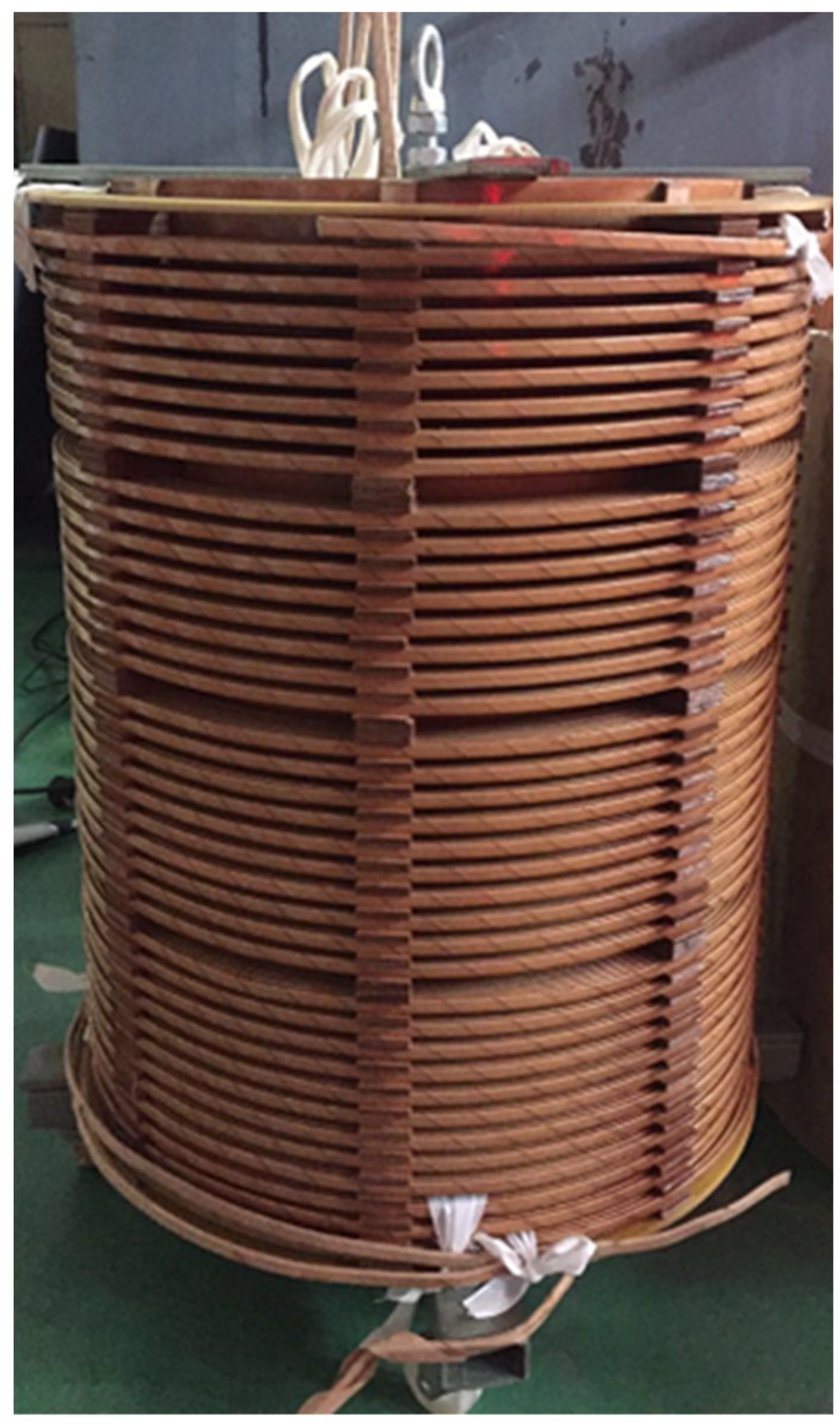
The dual partial discharge sources localization test platform in transformer oil consists of a transformer oil tank, F–P fiber optic sensor array, a Marx high-voltage pulse generator, and a needle-plate electrode that generates partial discharge. The transformer oil tank has dimensions of 200 cm × 100 cm × 150 cm and is filled with 25# transformer oil. The outer shell of the oil tank is grounded. The experimental transformer model is a 35 kV single-phase transformer with a height of 0.6 m, an outer diameter of 0.24 m and an inner diameter of 0.2 m for the high-voltage windings, and an outer diameter of 0.13 m and an inner diameter of 0.1 m for the low-voltage windings. The transformer core has a height of 0.6 m and a radius of 0.1 m. The turn-to-turn spacing of the windings is 0.6 cm. The actual scene image of the transformer is shown in
Figure 5.
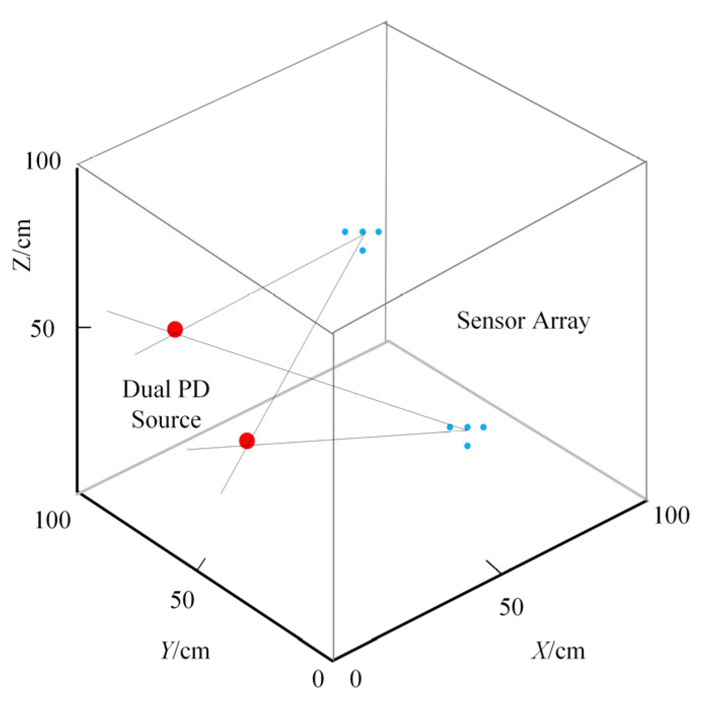
Based on past experience, two serially connected needle-plate electrodes can simultaneously undergo partial discharge under a high-voltage pulse of 20 kV. The sensor array is arranged at a 90° interval above the oil channel between the high and low voltage windings of the transformer, approximately 5 cm apart. According to the cross-localization principle, only four sensor arrays are required to localize dual partial discharge sources in the entire high and low voltage windings of the transformer. However, due to experimental limitations, this study employs two sensor arrays to detect and locate partial discharge sources within a quarter of the winding range. The experimental setup is illustrated in
Figure 6.
Based on the 3D rectangular coordinate system established for the array in
Figure 3, the spatial angles measured in the experiment include azimuth and elevation angles, which can be obtained from the line connecting the PD source and the origin of the coordinate system. In comparing similarity, the distance between the theoretical PD source position and the estimated position can be treated as the distance error.
4.1. Dual PD Sources Localization Test Results in Low-Voltage Winding
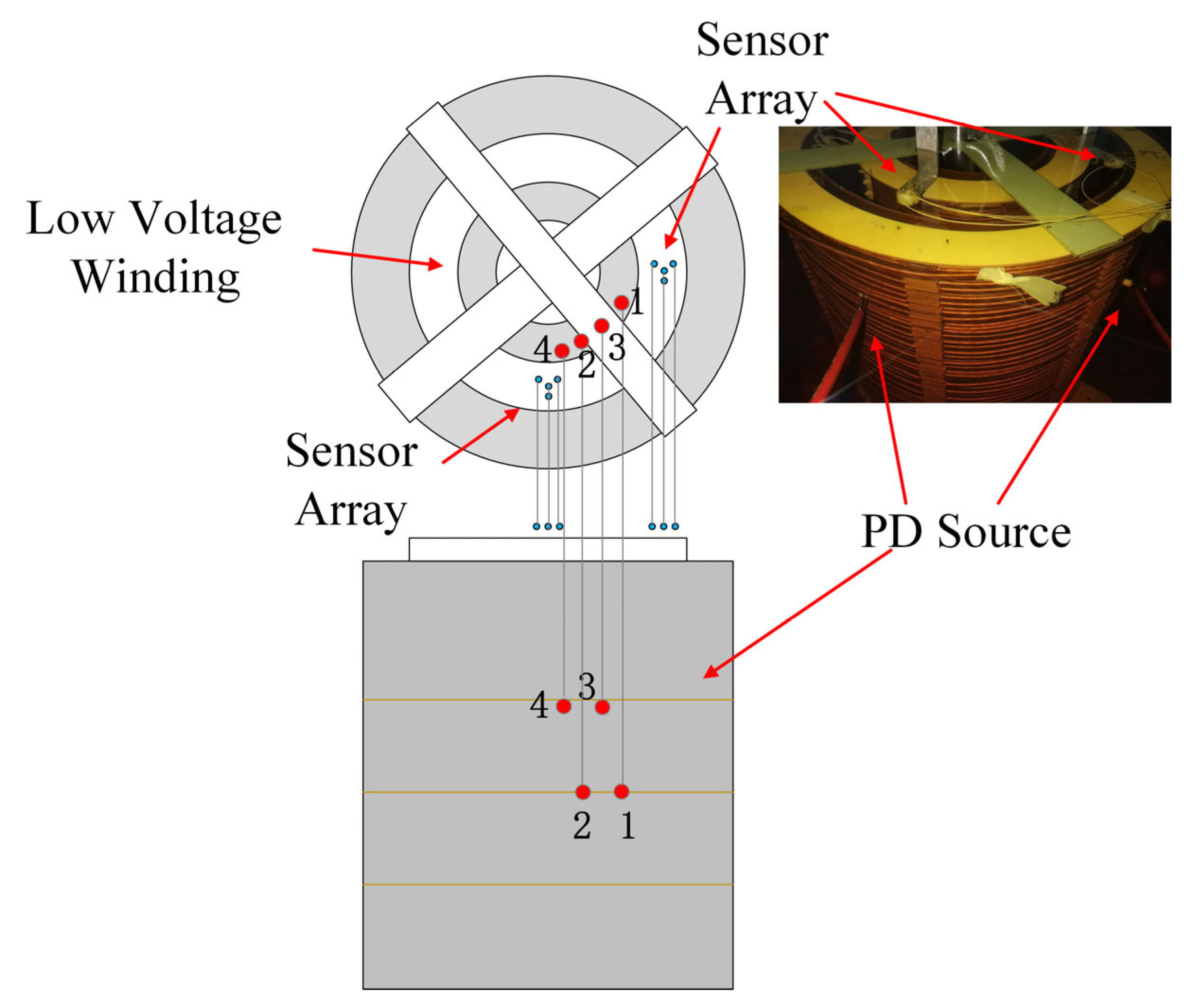
In the first experiment, two PD sources were placed at (11 cm, 40 cm, 10 cm) and (5 cm, 40 cm, 6 cm), within the low-voltage winding. After the occurrence of partial discharge, the signals captured by the F–P sensor array were processed through a localization algorithm, resulting in estimated positions of (10.9 cm, 51.2 cm, 11.4 cm) and (4.3 cm, 32.5 cm, 17.6 cm). According to the previous definition, the distance error was 11.3 cm. Subsequently, similar to the first experiment, the two PD sources were placed at three additional positions with different heights and deviation angles to evaluate the overall stability of the localization system. The experimental setup is illustrated in
Figure 7, and the experimental results are presented in
Table 1 (No. 2–4 group data).
Analysis of the data in the
Table 1 reveals that the average localization error of this method in the low-voltage windings is approximately 13.3 cm. Moreover, when the dual partial discharge sources occur on the same depth coil, the localization accuracy is slightly higher compared to two sources at different depths, as observed in the experimental data of Group 1 and Group 2. This is because, when the two PD sources are far apart, the time interval between the arrival of ultrasonic waves at the sensor array is larger, resulting in more refraction and reflection waveforms that can interfere with localization accuracy. For two PD sources located on the same layer of the coil, the deeper the position, the better the localization effect, as seen in data 1 and 4. This is due to the fact that, as the distance from the PD sources increases, the directivity of the F–P sensor array improves and, as the distance decreases, the error increases. Additionally, the cross-directional measurement algorithm itself has blind zones. Although placing it 5 cm above the oil duct can reduce the impact of blind zones, the localization error for the upper windings near the sensor array is slightly higher. Overall, the low-voltage windings have relatively fewer coil turns, resulting in less interference during ultrasonic wave propagation. Therefore, this method exhibits good accuracy in the localization of dual partial discharge sources in low-voltage windings.
4.2. Dual PD Sources Localization Test Results in High-Voltage Winding
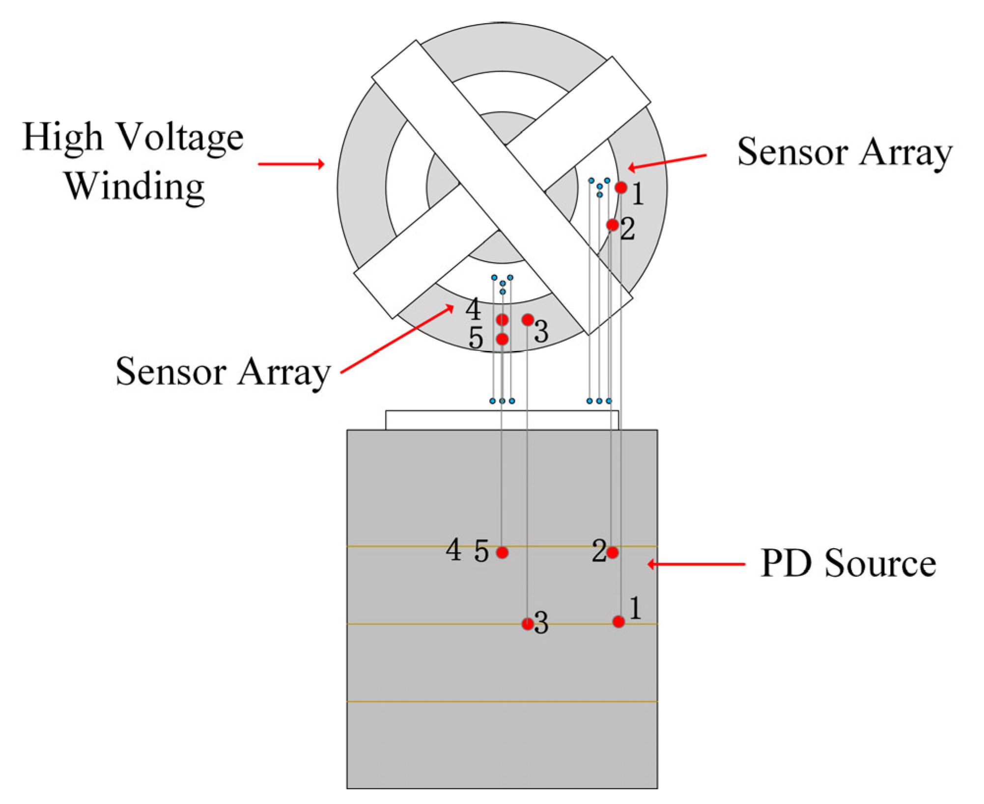
Based on the working principle of transformers, the number of turns in the high-voltage winding is higher than that in the low-voltage winding. Structurally, this manifests as the high-voltage winding being wider than the low-voltage winding. Therefore, five representative discharge positions were selected to verify the reliability of the localization algorithm. Similar to the localization research method for low-voltage winding, five test points with different depths and deviations were chosen on the side of the high-voltage winding of a 35 kV transformer. A schematic diagram of the experimental setup is shown in
Figure 8, and the localization results are presented in
Table 2.
Experimental results indicate that the average localization error of the double partial discharge sources in the high-voltage winding is 14.2 cm, which is higher than that of the low-voltage winding. This is due to the fact that the number of turns in the high-voltage winding is higher than that for the low-voltage winding. When ultrasonic waves pass through the windings to reach the sensor array, they encounter more reflections and refractions, which result in increased interference and localization errors. The deeper the partial discharge source, the more windings the ultrasonic signals have to pass through to reach the sensor array, and the more interference the signals encounter, leading to slightly higher localization errors. This can be observed from the data of No. 1 and No. 5, which show the impact of the depth of the partial discharge source on localization errors. However, the MUSIC algorithm has a high peak resolution, which reduces the impact of these interferences on localization accuracy. As can be seen from No. 3 and No. 6, although the partial discharge source 5 is located in the middle of the winding, its ultrasonic signals theoretically should encounter more interference from the windings, but the impact seems to be insignificant. This may be related to the randomness and contingency of the experiment. To reduce the localization distance error and minimize the interference from obstacles such as windings, further exploration is needed in optimizing the localization algorithm and the arrangement of the sensor array.
5. Conclusions
This paper develops a dual partial discharge source detection system for transformer windings based on the Fabry–Perot sensor array. By using the cross-localization algorithm based on the MUSIC algorithm proposed in this paper, fault localization within the windings can be achieved. Compared to traditional piezoelectric transducers, the tetrahedral-structured F–P sensor array designed in this study is compact, sensitive, strongly resistant to electromagnetic interference on-site, and possesses a high insulation rating. These arrays are capable of operating in the high-temperature and high-pressure environment inside transformers, adapting to various typical environmental characteristics within power transformers. Therefore, during the manufacturing process of power transformers, the sensors can be installed in proximity to the windings, such as above the oil duct between the high-voltage and low-voltage windings, to detect inter-turn partial discharge signals within the windings. The MUSIC algorithm enables high-resolution spatial spectrum estimation for dual partial discharge sources. Using the azimuth angles and pitch angles obtained, the proposed directional cross-localization algorithm can achieve localization of dual partial discharge sources within the windings using a relatively small number of sensor arrays. This system represents a significant step forward in improving the reliability and accuracy of partial discharge detection in power transformers.
Utilizing the dual PD localization system proposed in this paper, validation experiments were conducted separately on the high-voltage and low-voltage windings of a 35 kV single-phase transformer. Combined with the proposed dual PD localization algorithm, the localization errors meet the requirements for engineering applications. However, due to the complex conditions within transformer windings, further optimization of the sensor array placement positions is necessary. Additionally, novel signal processing methods should be employed to reduce the interference caused by the winding structure on ultrasonic signals, thereby enhancing the localization accuracy. These efforts will pave the way for more reliable and precise partial discharge detection in power transformers.

