Abstract
In this paper, a comprehensive analysis of the combined effect of major influencing parameters on heat transfer in a single U-tube BHE (sBHE) and a double U-tube BHE (dBHE) with two independent circuits was performed by using a validated numerical heat transfer model. Geometrical parameters, such as shank spacing (with maximum, average, and minimum values), borehole diameter (large, medium, and small borehole sizes), and borehole depth (shallow, average, and deep borehole depths) as well as the thermal conductivity of soil and grout, which ranges from minimum to high values, were considered. The combined impact of these parameters was included under the following four major cases: (1) the combined effect of borehole depth, borehole size, and shank spacing; (2) the combined effect of borehole depth and soil and grout thermal conductivity; (3) the combined effect of soil and grout thermal conductivity and borehole size; and (4) the combined effect of soil thermal conductivity, borehole size, and shank spacing. Each of these major cases has nine different design options for both sBHEs and dBHEs. A series of results of heat transfer per unit borehole depth were generated for all the considered various cases. With the given parameters, the BHE case that provides the highest heat transfer among the various cases of sBHEs and dBHEs were obtained.
1. Introduction
Ground source heat pump (GSHP) systems can be integrated with ground heat exchangers of different pipe installations as follows: horizontal (where continuous pipe loops are placed horizontally) and vertical (pipe loops are placed vertically). Most commonly, a GSHP system is integrated with vertical ground heat exchangers, called borehole heat exchangers (BHEs), where the working fluid that flows in the U-tube pipe exchanges heat with both the refrigerant of the heat pump and the ground around the borehole. As the basic component, a BHE is commonly coupled to a GSHP because of its flexibility, high efficiency, high heat transfer capacity in a limited area (Florides and Kalogirou [1]), and smaller land area requirement than horizontal ground heat exchangers Fang et al. [2]). However, the cost of installing a vertical ground heat exchanger is much higher (Rosen and Koohi-Fayegh [3]). On the other hand, horizontal ground heat exchangers are more economical in places where more land area is available, and trenches are easy to excavate (Florides et al. [4]). Among the various geometries of U-tubes (single, double, triple, and multiple U-tubes), BHEs with single and double U-tube configurations are commonly integrated with GSHP systems to provide space heating and cooling.
Various research studies have been performed on these two common BHE configurations with respect to heat transfer analysis, modeling, and performance comparison between the two. Specifically, these investigations mainly emphasized the heat transfer performance assessment of various BHE configurations and the effect of geometric parameters and thermo-physical properties of fluid, material, and groundwater movement on the overall heat transfer in BHEs, whereas other studies focused on comparative assessment of performance among different BHE configurations.
Over the last decade, the heat transfer performance of ground heat exchangers has become the core subject of several research investigations on BHEs with different configurations. In this regard, several researchers have studied the performance of BHEs through the development of different models for the prediction of heat transfer in borehole heat exchangers. The heat transfer performance of a BHE was studied by Molina-Giraldo et al. [5] through the development of a new analytical method (moving finite line source model) that considers the impact of groundwater flow and axial heat transfer. In their approach, the authors compared the new method with the previous standard finite line source model and the moving infinite line source model. Moreover, the new approach was validated with the 3D numerical model, and the temperature response predicted by the new method agreed well with the corresponding numerical solution. However, the model was restricted to a constant heat transfer per unit borehole length and it was not capable of analyzing variable heat loads or multiple boreholes. To evaluate the impact of unsaturated and inhomogeneous ground conditions on the performance of a vertical ground heat exchanger (BHE) with a single U-tube, Jung et al. [6] established a three-dimensional numerical transient heat transfer model and compared it with analytical infinite line source model. With the developed model, the authors evaluated the performance of the BHE in intermittent and continuous operation in both the heating and cooling mode of operation. Their simulation result revealed that the performance of the ground heat exchanger in unsaturated soil was reduced by 40% compared with that in saturated soil conditions. It was also reported that the ground temperature in the unsaturated condition revealed a larger variation than that below the groundwater table. Finally, the authors found that intermittent operation of the ground heat exchanger provided better thermal performance than that of continuous operation.
Using an experimental method, Luo et al. [7] evaluated the thermal performance of a double U-tube BHE integrated with a GSHP system that supplied heating and cooling effects for an office building. The impact of borehole diameter on thermal performance, and the effect of ambient temperature on the operation mode of the BHE was investigated. Their result indicated that the thermal performance of the BHE was slightly improved with increasing borehole diameter, and it was also found that ambient temperature strongly affected system operation. In order to study the thermal performance of a BHE, Yang et al. [8] developed an analytical heat transfer model that considers the variation in fluid temperature along the borehole length and thermal interference between two adjacent legs of a BHE. Using the developed model, the impact of various parameters on thermal effectiveness of the BHE was conducted. It was concluded that an enhancement in the thermal effectiveness of the BHE was primarily achieved by improving the thermal properties of the grout material and layout style of the U-tube and by increasing the spacing between two legs of the BHE. In addition, the thermal effectiveness was found to be independent of the fluid inlet temperature, borehole wall temperature, and fluid flow direction. Based on multipole theory, Hu et al. [9] developed an experimentally validated analytical heat transfer model to evaluate the heat transfer performance of a single U-tube BHE. The model improved the boundary shape restriction of the traditional analytic model; however, the heat transfer outside the BHE was not taken into consideration, and hence, the ground thermal response cannot be studied by this model. The authors performed dynamic simulations to investigate the impact of key borehole geometrical parameters and thermal properties on thermal effectiveness of the BHE. The results of their study indicated that increasing the thermal conductivity of grout and soil, widening the shank spacing, and increasing borehole depth and flow velocity improved the thermal effectiveness of the BHE. Using quasi-three-dimensional approach along with effectiveness-NTU (number of transfer units) theory, Conti et al. [10] developed an analytical heat transfer model that can effectively predict the thermal performance of a double U-tube BHE. Specifically, the authors proposed comprehensive expressions that can be used to determine the heat transfer rate per unit borehole length and the return temperature of the working fluid in a BHE with different geometric features, flow arrangements (series or parallel), and operating conditions. However, the proposed model cannot be applied for the application of short-time thermal responses. For example, the time evolution of the supply conditions from the heat pump unit cannot be predicted, and hence, the model cannot be applied to evaluate the thermal responses of a BHE that varies within a short period of time. Biglarian et al. [11] developed a 2D numerical heat transfer model along with a thermal capacity model that can be applied to perform dynamic simulations of heat transfer in a single U-tube BHE. The developed model can be applied to predict short- and long-term thermal responses of a single U-tube BHE, but it cannot be implemented for the prediction of the thermal performance of a BHE with a double U-tube configuration. Cao et al. [12] applied both experimental and CFD simulation methods to study the thermal performance of BHEs in terms of heat transfer per unit borehole depth and temperature difference (between inlet and outlet fluid temperature). The authors compared the thermal performance BHEs made of steel and polyethylene (PE) materials in both continuous and intermittent operating conditions. It was concluded that the BHE with a steel pipe exhibited better thermal performance and lower thermal resistance (with up to a 7% difference) than that of the BHE made PE material. To understand the overall heat transfer characteristics in borehole thermal energy storage, Zhu et al. [13] presented an experimentally validated three-dimensional numerical model that can predict unsteady heat transfer in a double U-tube BHE. Using the model, the authors analyzed transient thermal performance of the BHE and ground temperature distribution. They also studied the impact of borehole operating parameters on axial and radial ground temperature distributions while investigation of the impact of other factors (borehole geometrical parameters, thermal properties, permeability, groundwater movement, etc.) on thermal performance, but various temperature distributions were not covered in their study. To analyze transient heat transfer inside and outside of a single U-tube BHE, Kerme and Fung [14] presented a numerical heat transfer model. Various temperature distributions were investigated, and sensitivity analyses were also performed to investigate the impact of various borehole parameters on thermal performance and temperature distribution. In another investigation, Kerme and Fung [15] developed a numerical model that can predict transient heat transfer and temperature distributions for different cases of operating conditions of a double U-tube BHE.
Several investigations, which were mostly performed by developing a heat transfer model but also through experimental setups, have been completed on thermal performance comparison among different BHEs with different design configurations (Zeng et al. [16]; Li et al. [17]; Gao et al. [18]; Florides et al. [4]; Pu et al. [19]; Zhang et al. [20]; Conti et al. [10]; Adamovský et al. [21]; Fang et al. [2]; Sivasakthivel et al. [22]; Qi et al. [23]). To better understand the heat transfer process in a borehole heat exchanger (BHE), Zeng et al. [16] developed a quasi-three-dimensional analytical heat transfer model that considers vertical convective heat transfer and thermal interference between the legs of the BHE. Analytical expressions that could predict fluid temperature profiles along the borehole length as well as the total borehole thermal resistance were generated for single and double U-tube BHEs with various possible borehole configurations and fluid flow circuit arrangements. The result of their analysis revealed that double U-tube BHEs with parallel circuit arrangement exhibited better heat transfer thermal performance and less borehole thermal resistance than single- and double-BHEs with series configurations. Even though the model developed by Zeng et al. [16] can be utilized for cases of steady state performance analysis of BHEs, it cannot be used to evaluate the dynamic thermal performance of a BHE since steady state heat transfer within the BHE was assumed; moreover, vertical borehole wall temperature variation and ground temperature distribution cannot be predicted by their model. In order to examine the thermal performance of BHEs, Li et al. [17] prepared an experimental setup of a BHE with single and double U-tube borehole configurations. The authors investigated the impact of various conditions (such as soil and grout thermal properties, borehole operating conditions/modes, and the number of U-tube pipes) on the thermal performance of the BHE. The result of their investigation showed that the heat transfer rate per unit borehole depth of the double U-tube BHE was 50% and 45% more than that of the single U-tube BHE in the heat injection and extraction modes, respectively. Among the studied parameters, the heat transfer was highly influenced by the change in fluid inlet temperature; for instance, in the heat injection mode, it was found that when inlet temperature was increased by 5 °C (30 to 35 °C), the heat transfer rate per unit borehole depth improved by 20% and 100% for single and double U-tube BHEs, respectively.
Heat transfer performance of single and double U-tube BHEs and a multitube BHE in the cooling mode of operation was experimentally studied by Jalaluddin et al. [24]. The BHEs were compared in terms of heat transfer per unit borehole length for the same working condition. It was concluded that the double U-tube BHE exchanged the highest heat transfer, while the BHE with a single U-tube resulted in the lowest heat transfer rate. It was also found that the heat transfer rate of double U-tube and multitube BHEs increases with the highest flow rate, while it stays constant for the single U-tube BHE. In most of the BHE models, the ground around the BHE has been assumed to be homogeneous (i.e., the availability of different ground layers has been neglected). In order to overcome this short coming, Florides et al. [4] developed a 3D conduction and convective heat transfer model that can be applied to a BHE with single and double U-tubes surrounded by multiple layers of ground regime by dividing the vertical depth of the borehole into equal parts. Using the model, the authors investigated a performance comparison between single and double U-tube BHEs; they also studied the impact of multiple ground layers on the outlet temperature of the working fluid. Their results showed that a double U-tube with a parallel configuration was 26–29% more efficient than a BHE with a single U-tube. Furthermore, their results revealed that thermal energy was stored (distributed) more in the top layer. Adamovský et al. [21] experimentally investigated the performance of commonly utilized BHE configurations (single and double U-tubes) in terms of specific thermal power and specific thermal energy in the heating period. Their result revealed that a BHE with a double U-tube was more effective with more total specific energy and heat transfer rate per unit length than that of a single U-tube. An experimental setup was developed by Sivasakthivel et al. [22] in order to investigate the dynamic thermal performance of single and double U-tube BHEs (in both heating and cooling mode of operation). Their experimental result showed that the thermal potential for heat transfer and effectiveness was greater for double U-tube BHEs than that of single U-tube BHEs. The performance and ground temperature distribution of a GSHP system is substantially affected by the connection configuration (series and parallel) of ground heat exchangers. In order to examine this impact, Pu et al. [19] investigated the heating performance of a GSHP system both numerically and experimentally. It was concluded that ground heat exchangers with a parallel configuration resulted in greater thermal performance and a smaller pressure drop (between the inlet and outlet) than that of series configuration. Nevertheless, the authors did not study the profile of the thermal performance and pressure loss in turbulent flow conditions. A similar investigation was completed by Qi et al. [23], where a thermal performance comparison between BHEs linked in parallel and series configurations was performed based on an experimentally validated dynamic model. Similarly, their simulation result indicated that the BHE with a parallel configuration showed higher thermal performance than that of the BHE with a series configuration.
A number of studies have been conducted to investigate the variations in thermal performance of BHEs resulting from changes in BHE geometry such as pipe separation. According to Makasis et al. [25], the commonly held assumption that vertical pipes (loops) of the BHE remain equally spaced over the length of the borehole can result in thermal interference and degrade system performance. Using a model with a sinusoidal-based pipe geometry, these researchers evaluated the influence of this interference by comparing different geometries and modeling both constant and variable pipe separations. They identified some significant design parameters and found that backfill material could reduce the negative effects of thermal interference by up to 60%. More recently, Choi et al. [26] used probabilistic uncertainty quantification to investigate the thermal resistance of BHEs. They used Monte Carlo simulations to probabilistically quantify the uncertainty in thermal resistance caused by uncertain characteristics, considering four scenarios. They found that the use of spacers greatly improved thermal resistance and reduced its uncertainty range, and their results suggested that thermal response tests cannot sufficiently represent the entire borefield. Sandler et al. [27] evaluated the impact of the thermal shunt effect (TSE) on the overall performance of BHEs. They found that TSE increased with larger borehole depths, pipe diameters, and pipe-to-pipe spacings, and they found that pipe arrangement had a great impact on elimination of TSE in deep U-pipes. However, these studies have not included the comparison between single and double U-tube BHE.
A number of research investigations have also been conducted on sensitivity analyses of parameters or factors that significantly impact the rate of heat transfer in a borehole heat exchanger (BHE), as stated in various studies in the literature (Zeng et al. [16]; Hu et al. [9]; Casasso and Sethi [28]; Minaei and Maerafat [29]; Tang and Nowamooz [30]; Kerme and Fung [14]; Zhang et al. [31]). These investigations mainly focused on the effect of borehole geometrical parameters such as borehole depth (Jun et al. [32]; Sandler et al. [27]; Chen et al. [33]; Li et al. [34]; Casasso and Sethi [28]; Zhai et al. [35]), borehole diameter (Luo et al. [7], Minaei and Maerafat [29]), and shank spacing (Jun et al. [32]; Casasso and Sethi [28]; Zhang et al. [36]; Minaei and Maerafat [29]). The results of these studies revealed that the thermal performance of BHEs improves with increasing borehole diameter, borehole depth, and shanks spacing. The effect of the pipe material of a BHE (Cao et al. [12]) and pipe diameter (Zhang et al. [36]; Zhou et al. [37]) was also investigated, and it was concluded that thermal performance slightly improves with pipe outer diameter and pipe material. Various researchers have also examined the effect of thermal conductivity of grout and ground/soil on the thermal performance and design of BHEs (Jun et al. [32]; Casasso and Sethi [28]; Zhang et al. [36]; Han and Yu [38]; Minaei and Maerafat [29]; Kerme and Fung [14]). A number of studies emphasizing the impact of BHE operating parameters such as fluid inlet temperature (Jun et al. [32]; Zhang et al. [36]; Han and Yu [38]) and flow velocity (Jun et al. [32]; Zhou et al. [37]; Jalaluddin et al. [24]; Han and Yu [38]) have also been conducted.
However, the aforementioned research works are not comprehensive as they deal with the impact of only a single or a few parameters. The detailed combined impact of increasing grout and/or soil thermal conductivity along with borehole geometrical parameters (borehole size or diameter, shank spacing) on the total heat transfer per unit borehole depth was not investigated. For example, if a BHE with a deep or shallow borehole depth with low or high grout thermal conductivity is required to be designed to deliver the highest heat transfer rate per unit borehole depth, then which of the design case options for the BHE is the best to consider? Is it better to consider an sBHE or a dBHE with a large or small borehole size, high or low shank spacing, and low or high soil thermal conductivity? The responses to such important BHE design questions were not covered in the previous studies of BHEs. In fact, these questions cannot be easily answered, as simple as they seem, since the heat transfer in a BHE is complex and needs thorough analysis. Hence, investigating the combined effect of BHE parameters in a systematic approach is important.
Because of the complex nature of heat transfer in a BHE, the presentation of this heat transfer in a tabular/graphical form that enables BHE designers to conveniently and easily select the case that suits/fulfills their respective thermal design requirement (i.e., high heat transfer) is highly demanded. Such a detailed investigation of the overall impact of various parameters on heat transfer in a BHE is used as a quick reference for the design and optimization of a BHE integrated with a GSHP system. Such an investigation has not been performed before. Hence, a comprehensive sensitivity analysis that involves combined impact of parameters is currently necessary.
Therefore, in this paper, the combined effect of major influencing parameters that affect heat transfer in single U-tube BHEs (sBHEs) and double U-tube BHEs (dBHEs) was performed. The combined impact of different parameters was included and studied under the following four major cases: the combined effect of borehole depth, borehole size, and shank spacing; the combined effect of borehole depth and soil and grout thermal conductivity; the combined effect of soil and grout thermal conductivity and borehole size; and the combined effect of soil thermal conductivity, borehole size, and shank spacing. Each of these major cases has various design options of sBHEs and dBHEs. Using a validated numerical heat transfer model, a series of heat transfer data in graphical form that helps to investigate the combined impact of various parameters on heat transfer per unit borehole depth was generated for all the considered cases. Among the various cases of sBHE and dBHE, the case that provides highest heat transfer per unit borehole depth was also specified.
Furthermore, the impact of convection heat transfer coefficient and flow regime on heat transfer per unit borehole depth of a sBHE and a dBHE was studied. Evaluation of total pressure loss in the BHEs as well as pumping power required to circulate the fluid in the BHEs was made, and the two BHEs were also compared in terms of total pressure loss/head loss as well as pumping power.
The proper design and optimization of BHEs is crucial for improving the overall thermal performance and total cost of the GSHP system, making it more attractive for widespread adoption. As a result, the design of BHEs is crucial for design and performance analysis of GSHP systems. On the other hand, the heat transfer in BHEs is complex as it involves different modes of heat transfer processes that depends on multiple factors such as borehole geometrical parameters, thermal properties, flow types, geological conditions (underground water flow), etc. The heat transfer process in BHEs includes conduction (which occurs in the ground, the backfill material, and the pipe walls and partially in the fluid) and convection, which occurs primarily in the heat transfer fluid. Because of this heat transfer complexity, the thermal design of a BHE must consider the overall dynamics of the BHE, which can be used for the proper design of the GSHP system integrated with the BHE.
Overall, the four major cases considered in the analysis are significant because they help to identify the combined effects of various parameters on the heat transfer performance of single and double U-tube borehole heat exchangers (BHEs). The result of this study is important as it serves as a quick reference in the design and optimization of single and double U-tube BHEs that can be integrated with ground source heat pump systems.
2. Description of the Adopted Model
The heat transfer mechanism in a BHE consists of convection between the working fluid and tube wall, conduction through the tube wall and backfill material, conduction between the legs of U-tubes, and the conduction between the backfill material and the soil/ground. The evaluation of the total heat transfer in the BHE is performed by considering the borehole region as inside and outside, and the analysis of the two regions are related by the surface (wall) temperature of the borehole. For the simulation and analysis of heat transfer in the single and double U-tube BHEs, our previously developed model (Kerme and Fung [15]) was adopted. Firstly, the numerical model is developed for the double U-tube BHE and then this model is modified to allow for the simulation and analysis of the BHE with a single U-tube configuration. This applied numerical model, which was developed from energy balance performed on nodes inside and outside the BHE, is presented in detail in our previous work (Kerme and Fung [15]). The differential heat transfer equations that govern the heat transfer between the fluid in the BHE and the soil/ground are obtained by performing energy balance on fluid, grout, and ground elements. These heat transfer equations are then discretized in order to be solved by a numerical method. Because of its high accuracy and stability, the implicit numerical method proposed by Crank–Nicolson (Nellis and Klien [39]) is implemented to iteratively solve the equations at each time step. MATLAB is used as the numerical solving tool.
A sectional view of the double U-tube configuration and geometrical borehole parameters is shown in Figure 1. The tubes are considered symmetrically placed in the borehole with the following two independent circuits: 1–3 and 2–4. In the considered parallel 1–3, 2–4 arrangement, 1 and 2 are the inlets, while 3 and 4 are outlets, of the working fluid. Arrangement 1–3 was considered for the single U-tube BHE configuration.
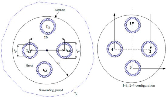
Figure 1.
Borehole parameters and a cross-section of the borehole configuration.
Different thermal resistances of the fluid and grout inside the considered vertical double U-tube BHE and the surrounding soil thermal resistances are shown in Figure 2a. The corresponding single U-tube configuration is obtained by removing one U-tube from the double U-tube configuration shown in Figure 1 without altering the other geometrical parameters. The corresponding thermal circuit of the BHE with a single U-tube is presented in Figure 2b.
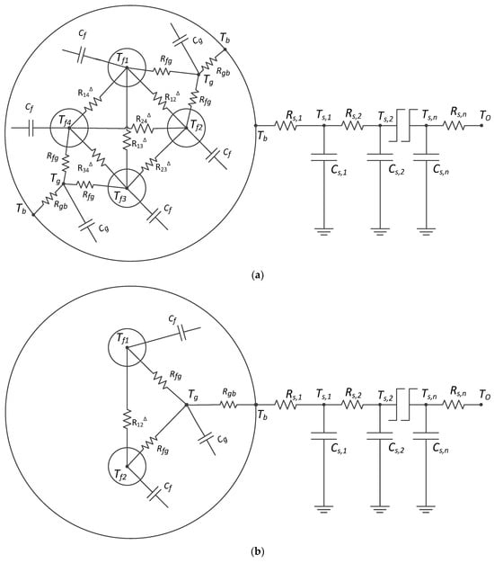
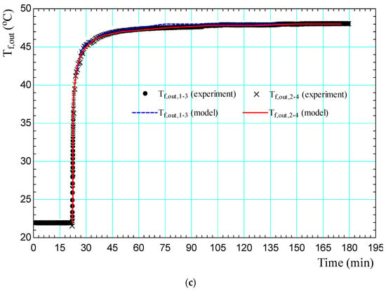
Figure 2.
(a) Thermal circuit of the BHE with a double U-tube configuration. (b) Thermal circuit for the BHE with a single U-tube configuration. (c) Model-predicted and experimental working fluid outlet temperatures.
The governing heat transfer Equations (1)–(6) are obtained by performing energy balance on fluid, grout and ground nodes outside the borehole (Kerme and Fung [15]).
The heat transfer equation for the fluid node in tube-1 is given by the following equation:
In Equation (1) and the other equations, i designates the location of the node in the vertical direction; i − 1 and i + 1 in all equations represent the upper and lower nodes with respect to node i, the fluid element on which the energy balance was performed.
Similarly, the heat transfer equation for the ith fluid node in tube-2 is given as:
The governing equation for the ith fluid node in tube-3 is obtained by:
Likewise, energy balance performed on the ith fluid element inside tube-4 provides the following equation:
The governing heat transfer equation for the ith grout node is given by the following equation:
The governing heat transfer equation for the soil node outside the BHE is given by:
In Equation (6), i and k represent the location of the node in the vertical and radial directions, respectively. To solve the above equations, an implicit numerical method was adopted because of its ensured stability. In this regard, an implicit Crank–Nicolson numerical approach, which has high accuracy and unconditional stability, was utilized to solve the developed differential heat transfer equations (Nellis and Klein [39]).
According to the Crank–Nicolson approach, the temperature at time step j + 1 is given by:
Equation (7) is then applied on each of the Equations (1)–(6).
The heat transfer outside the borehole (or the ground temperature around the borehole) varies in the axial and radial directions. Thus, the corresponding Crank–Nicolson equation for the soil node (where i and k represent the location of the node in the vertical and radial directions, respectively) outside the borehole is given by:
Finally, all Equations (1)–(7), except Equations (2) and (4), are also the heat transfer modeling equations for the corresponding BHE with a single U-tube configuration. Hence, various temperature and heat transfer profiles for the corresponding single U-tube BHE can be obtained by using these equations.
To solve the above modeling equations, the following boundary conditions were applied (Kerme and Fung [15]):
- For the upper fluid node in tube 1 and tube 2, the temperature will become and , respectively, and it will be the same as the inlet temperature of the working fluid in the corresponding U-tubes. That is, and . The fluid inlet temperature in tube 1 and 2 can be the same or different.
- For both U-tubes, the fluid temperature of the last nth node of the downward flow pipe is the same as the temperature of the fluid entering the upward flow pipe: and .
- For the ground nodes outside the borehole:
- The temperature of the far-field boundary is assumed to be the same as the undisturbed ground temperature (To = 10 °C).
2.1. Modeling of Heat Transfer and Other Parameters
In this subsection, analytical expressions that are used to calculate various thermal resistances in the modeling equations are given. In addition, equations that describe the total heat transfer between the fluid and ground, the borehole thermal resistance, and the thermal effectiveness of the BHE are provided.
The total heat transfer rate per unit depth between the fluid and the ground around the single and double U-tube BHEs is evaluated by Equations (9a) and (9b), respectively (Biglarian et al. [11]; Kerme and Fung [15]):
where for single and double U-tube BHEs is given by Equations (10a) and (10b), respectively (Zeng et al. [16]; Zeng et al. [40]).
where , , and are evaluated by the following expressions (Zeng et al. [40]):
where and are the thermal conductivities of the grout and soil (ground), respectively.
is the sum of the thermal resistances of the internal convection and pipe wall, and it is evaluated by:
where is the convection heat transfer coefficient. Since the flow in the U-tube may not be fully turbulent, the Gnielinski [41] correlation, which is valid for turbulent flow down to transitional flow, is applied to evaluate the convection heat transfer coefficient () as given by Equation (13a), while for laminar flow, the corresponding is evaluated by Equation (13b) (Shah and Sekulic [42]; Beier et al. [43]).
In Equation (13a), D is the inside diameter of the U-tube pipe; Pr is the Prandtl number; and ReD is the Reynolds number. The Darcy friction factor () for turbulent flow can be estimated by the correlation (Colebrook [44]) given by Equation (14a), while for laminar flow (, can be calculated by Equation (14b) (Fox et al. [45]):
In Equation (14a), D is the inside diameter of the U-tube pipe; is the roughness, and its value for PVC and for drawn tubing is 0.0015 mm (Fox et al. [45]).
The other important parameter that needs to be evaluated for a BHE is the total borehole thermal resistance (), which is the sum of the conductive resistance of the backfill material, conductive resistance of the pipe wall, and the convective resistance between the fluid and pipe wall. Borehole thermal resistance for the single and double U-tube BHE can be obtained as in Equations (15a) and (15b), respectively (Minaei and Maerafat [46]).
where is the sum of the thermal resistance of the convection and pipe wall and is the grout thermal resistance. The Bauer et al. [47] expression for grout thermal resistance, which was improved for the four legs of the double U-tube, as reported by Javed and Spitler [48], is given by:
The grout thermal resistance for the single U-tube BHE is evaluated by the best-fit correlation suggested by Liao et al. [49], which is given by the following expression:
The thermal resistance between the working fluid and grout for double U-tube and single U-tube BHEs is obtained by the following Equations (18a) and (18b), respectively (Minaei and Maerafat [46]):
The grout-to-borehole wall thermal resistance () is evaluated by (Minaei and Maerafat [46]):
where and are the location of the grout node and equivalent radius, respectively.
The pumping power reaching the fluid (which is required to maintain the circulation of the fluid in the closed loop of the BHE) and the total pressure drop in the total pipe length of the BHE are other important factors (parameters) that must be considered in the performance study of the BHE. The useful pumping power that is required to keep the circulation of the working fluid in the closed loop of the borehole heat exchanger (BHE), the total pressure drop between the inlet and outlet of the U-tube pipe, and the corresponding total head loss are given by the following equation:
where is the total mass flow rate; V is fluid velocity; is the friction factor evaluated by Equation (14); D is internal U-tube pipe diameter; is the total pressure loss between the inlet and outlet of the U-tube pipe; is the total head loss; and is the loss factor, where a value of 0.2 was used taking the U-tube as a return bend. The total length (L) in Equation (20) is twice and four times of the borehole depth (H) for single and double U-tube BHEs, respectively.
2.2. Validation of the Model
To prove the reliability of the applied model, the fluid outlet temperature is validated against experimental result of Marcotte and Bernier [50], as shown in Figure 2c. The experimental setup developed by Marcotte and Bernier [50] was a laboratory model of a double U-tube borehole (90.39 cm long with 9.45 cm diameter) placed in a sand tank with identified properties. To validate the fluid outlet temperature, a test with a step change in inlet temperature, where a step change of 26.4 °C was imposed in both circuits for a period of 3 min, was considered. The same working fluid conditions (fluid inlet temperature of 48.5 °C and mass flow rate of 0.75 kg/min) and borehole parameters as presented by Marcotte and Bernier [50] in their experimental work were employed as inputs to the current model. The results of the validation are presented in Figure 2c, which shows that the predicted fluid outlet temperature from our model exhibits a similar trend and is in good agreement with the experimental data. Furthermore, we calculated the coefficient of determination (R2) and root mean square error (RMSE) between the model predictions and the experimental data, which were found to be approximately 99.4% and 0.65%, respectively. These results indicate a good agreement between the model and experimental results, supporting the reliability of our model.
3. Results and Discussion
3.1. Analysis of Major Influencing Parameters on the Performance of Borehole Heat Exchangers
A borehole heat exchanger (BHE) is the key component of the ground source heat pump system (GSHP) that delivers space heating and cooling of buildings. It determines the overall thermal performance of the GSHP system. In addition, the total cost of the GSHP system depends on the installation and drilling cost of the BHE.
Because of the complex nature of heat transfer in the BHE, the proper modeling and thermal design of a BHE that meets the required demand is still challenging. In the design of a BHE, thermal performance is an important parameter that determines the effective heat transfer between the soil and GSHP system. Moreover, the thermal performance of a BHE also determines effectiveness of the operational and running cost of the GSHP system. As a result, comprehensive investigation of BHEs from the perspectives of the combined impact of different factors (borehole geometrical parameters and thermal properties) that affect their thermal performance is indispensable.
Heat transfer in a BHE is affected by various factors including geometrical, thermal, geological, and operational parameters. In this regard, investigating the combined effect of parameters in a systematic approach is important. Because of the complex nature of heat transfer in a BHE, the presentation of this heat transfer in a tabular/graphical form that enables one to conveniently and easily select the case that suits/fulfills the respective thermal design requirement (i.e., high heat transfer) is highly demanded. Such a detailed investigation of the overall impact of various factors on heat transfer in a BHE is used as quick reference for the design and optimization of a BHE integrated with a GSHP system. In this paper, the combined effect of major influencing parameters that affect the performance of both single U-tube BHEs (sBHEs) and double U-tube BHEs (dBHEs) was performed. For the sake of convenience, the combined impact of different parameters is included under the following four major cases (where each of them has nine different sub-cases, as shown in Table 1):

Table 1.
The four major cases considered to investigate the combined effect of different parameters on the performance of the sBHE and dBHE.
- (A)
- The combined effect of borehole depth (H), borehole size (Db or rb), and shank spacing (Xc);
- (B)
- The combined effect of borehole depth (H) and soil (ks) and grout (kg) thermal conductivities.
- (C)
- The combined effect of soil (ks) and grout (kg) thermal conductivities and borehole size (Db or rb);
- (D)
- The combined effect of soil thermal conductivity (ks), borehole size (Db or rb), and shank spacing (Xc).
The values of the fixed borehole geometrical parameters and thermal properties considered under each case study are listed in Table 2.

Table 2.
Fixed input values of parameters and thermal properties used in the analysis.
- A.
- Combined Effect of Borehole Depth, Borehole Size, and Shank Spacing
The optimal design of a borehole heat exchanger (BHE) for a ground source heat pump (GSHP) system depends on various factors such as geometrical parameters (borehole depth, borehole size (diameter), and shank spacing), soil thermal conductivity, and others. Borehole depth is particularly important because it affects both the performance and cost of a BHE. Although deeper borehole depth may seem to increase the performance of a BHE, it can also lead to thermal interaction between the legs of the BHE, which can reduce heat transfer between the working fluid and the ground. Furthermore, deeper boreholes are more expensive to drill. Various questions arise on BHEs. One question is whether a single or double U-tube BHE has lower thermal interaction between legs (thermal short-circuit) at deep borehole depths. Another question is whether it is better to use a deep BHE with small or large shank spacing and with medium or high soil thermal conductivity, and it is important to determine which borehole configuration, sBHE or dBHE, is preferable in each scenario.
Borehole size (diameter) is another crucial geometrical parameter impacting heat transfer in BHEs. While larger boreholes are generally preferred to enhance heat transfer between the working fluid and the surrounding ground, it is unclear whether small, medium, or large boreholes are most effective for shallow or deep boreholes, as other parameters also play a significant role. Furthermore, increasing borehole size raises the cost of the BHE. Another geometrical parameter that affects the heat transfer in the BHE is the shank spacing, which is the center-to-center distance between U-tube legs of the BHE.
Overall, the heat transfer in the BHE is complex and depends on multiple factors, and hence, comprehensive sensitivity analysis that considers the combined impact of all parameters should be performed. Investigating the single impact of one parameter on the heat transfer in a BHE is inadequate to determine the variation in the total heat transfer in the BHE. A comprehensive investigation that involves the combined effect of various parameters on heat transfer is highly needed for the design and optimization of BHEs. Therefore, presenting the variation in the total heat transfer rate per unit borehole depth with different borehole parameters and thermal properties in a convenient way, such as in tabular or graphical form, is essential. A series of heat transfer data in tables/graphs can be conveniently implemented during the thermal design of a BHE. In other words, when the results of such case studies of BHEs with different options of various parameter is available, then BHE designers can utilize such result as a quick reference for the thermal design and optimization of BHEs that can be integrated with GSHP systems.
To fully assess such a combined effect of parameters on total heat transfer per unit borehole depth, an analysis involving the combined impact of borehole depth, borehole radius, and shank spacing with different cases of soil and grout thermal conductivities was performed in this section. The analysis in this subsection was completed for both the sBHE and dBHE with as follows: small borehole size (Db = 100 mm and a half shank spacing of Xc = 0.034 m (maximum), Xc = 0.025 m (medium), and Xc = 0.016 m (minimum)); medium borehole size (Db = 146 mm and a half shank spacing of Xc = 0.057 m (maximum), Xc = 0.037 m (medium), and Xc = 0.016 m (minimum)); and large borehole size (Db = 200 mm and a half shank spacing of Xc = 0.084 m (maximum), Xc = 0.05 m (medium), and Xc = 0.016 m (minimum)). This case considering the combined effect of borehole depth, borehole size, and shank spacing was performed for nine different cases of combined values of grout and soil thermal conductivities (with minimum, medium, and maximum values), as shown in Table 3. This case is important as a quick reference for the design of BHEs with the given nine cases of thermal conductivities of grout and soil. Then, one can select the case that provides the highest heat transfer among the various cases of sBHEs and dBHEs presented in column A of Table 1. The results of these cases are presented in Figure 3, Figure 4, Figure 5, Figure 6, Figure 7 and Figure 8. Various types of important information can be obtained from such results.

Table 3.
The nine sub-cases considered under each major cases of A to D.
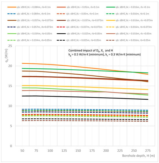
Figure 3.
Combined effect of borehole depth, borehole size, and shank spacing on the heat transfer rate per unit borehole depth in the sBHE and the dBHE for the case of minimum grout and soil thermal conductivities (kg = 0.5 W/m∙K, ks = 0.3 W/m∙K).
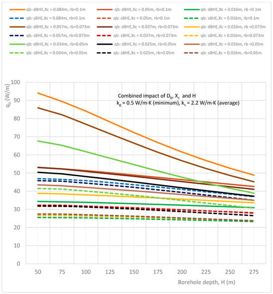
Figure 4.
Combined effect of borehole depth, borehole size, and shank spacing on the heat transfer rate per unit borehole depth in the sBHE and the dBHE for the case of minimum grout conductivity and average soil thermal conductivity (kg = 0.5 W/m·K, ks = 2.2 W/m·K).
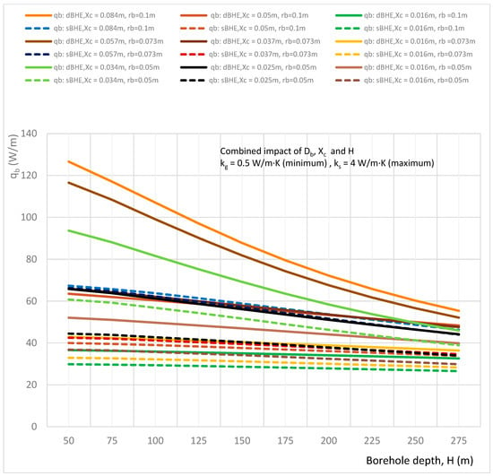
Figure 5.
Combined effect of borehole depth, borehole size, and shank spacing on the heat transfer rate per unit borehole depth in the sBHE and the dBHE for the case of minimum grout conductivity and maximum soil thermal conductivity (kg = 0.5 W/m·K, ks = 4 W/m·K).
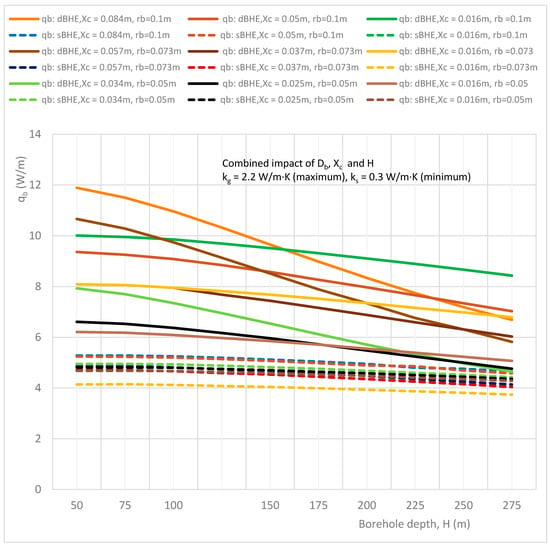
Figure 6.
Combined effect of borehole depth, borehole size, and shank spacing on the heat transfer rate per unit borehole depth in the sBHE and the dBHE for the case of maximum grout thermal conductivity and minimum soil thermal conductivity (kg = 2.2 W/m·K, ks = 0.3 W/m·K).
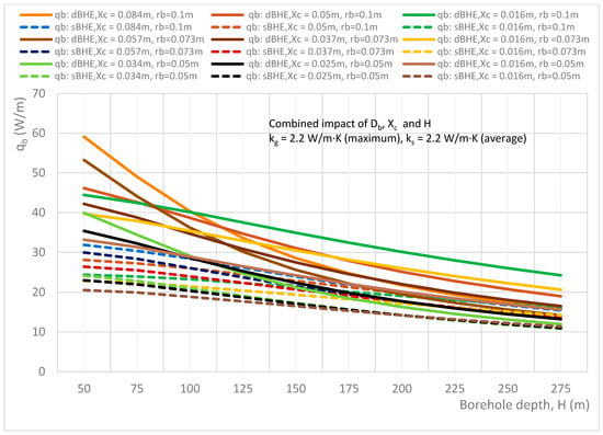
Figure 7.
Combined effect of borehole depth, borehole size, and shank spacing on the heat transfer rate per unit borehole depth in the sBHE and the dBHE for the case of maximum grout thermal conductivity and average soil thermal conductivity (kg = 2.2 W/m∙K, ks = 2.2 W/m∙K).
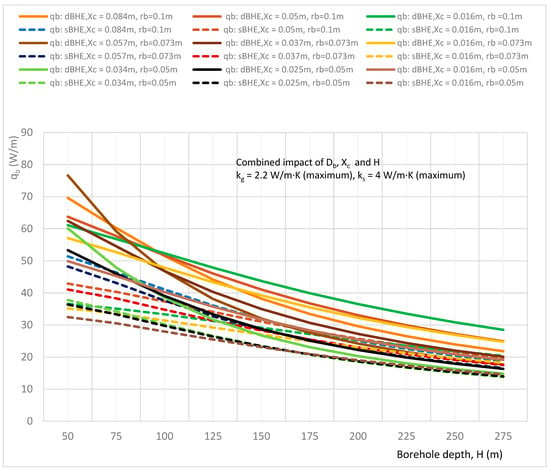
Figure 8.
Combined effect of borehole depth, borehole size, and shank spacing on the heat transfer rate per unit borehole depth in the sBHE and the dBHE for the case of maximum grout and soil thermal conductivities (kg = 2.2 W/m∙K, ks = 4.0 W/m∙K).
Figure 3, Figure 4 and Figure 5 illustrate the combined impact of borehole depth, borehole size, and shank spacing on the heat transfer rate per unit borehole depth for minimum grout and soil thermal conductivities (kg = 0.5, ks = 0.3 W/m∙K), minimum grout and medium soil thermal conductivities (kg = 0.5, ks = 2.2 W/m∙K), minimum grout and maximum soil thermal conductivities (kg = 0.5, ks = 4 W/m∙K), respectively. A comparison of the results depicted in Figure 3, Figure 4 and Figure 5 shows that the case with minimum grout and maximum soil thermal conductivities (shown in Figure 5) provides a higher heat transfer rate per unit borehole depth than all the other cases, while the case with minimum grout and soil thermal conductivities (shown in Figure 3) provides the lowest heat transfer rate. In Figure 3, it is also interesting to note that when both the grout and soil thermal conductivity values are minimum, the dBHE (because of its greater surface area) transfers more heat than the sBHE. This is also seen in the other remaining cases. On the other hand, for the other cases of thermal conductivities, the sBHE becomes better at transferring more heat than the dBHE, particularly at deep borehole depths; for example, the sBHE with a large borehole size and maximum shank spacing (rb = 0.1 m and Xc = 0.084 m) seem to provide more heat transfer than the dBHE with a large borehole size and minimum shank spacing (rb = 0.1 m, Xc = 0.016 m). As it can be seen in the trends shown in Figure 4 and Figure 5, it seems that for a deep borehole depth, the sBHE transfers more heat than the dBHE. The reason for this is that as the borehole depth increases, the short-thermal circuit (thermal interaction between the U-tube legs) increases, and its impact becomes greater in the dBHE than in the sBHE. A close look at Figure 4 and Figure 5 also shows that (when grout conductivity is low and soil thermal conductivity is at an average or a high value), using a BHE with maximum shank spacing is effective for the largest borehole size, while using minimum shank spacing is more effective for a BHE with the smallest borehole size. This could also be attributed to the phenomenon of thermal short-circuit.
Overall, the results depicted in Figure 3, Figure 4 and Figure 5 reveal that the dBHE is preferable to transfer more heat when used at a shallow borehole depth, while for the BHE with deep borehole depth, the sBHE is better able to exchange more heat between the working fluid and the ground than the dBHE. Figure 3, Figure 4 and Figure 5 also show that in both the sBHE and the dBHE, the BHE with a large borehole size (rb = 0.1 m) and maximum shank spacing (Xc = 0.084 m) provides the highest heat transfer. This could be due to the greater surface area available for heat transfer when the borehole size is enlarged and the U-tubes are widely spaced.
The results generated for the case of the average grout thermal conductivity is almost similar to the to the other results, and hence, it is not discussed here. The simulations result generated for the combined impact of borehole depth, borehole size, and shank spacing on the heat transfer rate per unit borehole depth in the sBHE and the dBHE for the cases of maximum grout thermal conductivity (kg = 2.2 W/m·K) combined with minimum, average, and maximum soil thermal conductivities are illustrated in Figure 6, Figure 7 and Figure 8. In these cases, although the grout thermal conductivity is maximum, the heat transfer per unit borehole depth is lower than all other corresponding cases discussed previously (cases 1 to 6 in Table 3), as depicted in Figure 3, Figure 4, Figure 5, Figure 6, Figure 7 and Figure 8. This is because employing excessive thermal conductivity of backfill-material in the BHE may produce thermal interference (thermal short-circuit) between the U-tube pipe legs, leading to reduced heat transfer, and hence, reduced BHE performance. The phenomenon of short thermal circuit for the cases in Figure 6, Figure 7 and Figure 8 could be more for the dBHE with a deep borehole depth than the sBHE, and it is also relatively higher than the other previously discussed cases in this subsection.
For the case of low soil thermal conductivity (ks = 0.3 W/m·K) shown in Figure 6, all the considered dBHE cases transfer more heat than the corresponding sBHE cases. However, at a deep borehole depth, the sBHE (with a large borehole size and high shank spacing) seems to transfer more heat than the dBHE with a small borehole size. This impact is more augmented for the other cases in the next subsection. That is, at a deep borehole depth, the heat transferred by the dBHE with a large borehole size (rb = 0.1 m) and maximum shank spacing (Xc = 0.084 m) is significantly reduced and becomes lower than that of the corresponding sBHE. In addition, as shown in Figure 6, Figure 7 and Figure 8, the dBHE with maximum shank spacing provides more heat transfer than all the other cases when used at a shorter borehole depth; while the dBHE with minimum shank spacing is preferable to transfer more heat into the ground when applied at a deeper borehole depth. Similarly, in the sBHE, the BHE with the largest borehole size and maximum (highest) shank spacing is preferred to deliver more heat transfer into the ground when employed at a shallow borehole depth (see Figure 7 and Figure 8).
Overall, among the nine cases listed under the combined effect of borehole depth, borehole size, and shank spacing depicted in Figure 3, Figure 4, Figure 5, Figure 6, Figure 7 and Figure 8, increasing the borehole size and shank spacing is more effective in transferring more heat irrespective of borehole depth for case 3, and the dBHE with a large BH size and maximum shank spacing employed with low grout thermal conductivity and maximum soil thermal conductivity provides the highest heat transfer per unit borehole depth. On the other hand, the lowest heat transfer is obtained for case 7, where the backfill material with maximum thermal conductivity (kg = 2.2 W/m·K) is used in the BHE installed at ground level with low soil thermal conductivity (0.3 W/m·K). The reason for this could be the thermal short circuit (thermal interference) associated with excessive thermal conductivity of the grout utilized in the BHE.
- B.
- Combined Effect of Borehole Depth and the Thermal Conductivities of Soil and Grout
In this section, an analysis of combined impact of parameters (which include borehole depth and soil and grout thermal conductivities) on the total heat transfer per unit borehole depth with different cases of borehole size (radius) and half shank spacing (half center-to-center distance between U-tube pipes) is performed. Specifically, the sensitivity analysis is performed for minimum (low) soil thermal conductivity (ks = 0.3 W/m∙K), average soil thermal conductivity (ks = 2.2 W/m∙K), and maximum (high) soil thermal conductivity (ks = 4 W/m∙K), where each value of soil thermal conductivity is combined with minimum (kg = 0.5 W/m∙K), average (kg = 1.5 W/m∙K), and maximum (kg = 2.2 W/m∙K) values of grout thermal conductivity. This is indicated in Table 1 and Table 3 in column B. This case of the combined effect of borehole depth, soil thermal conductivity and grout thermal conductivity was performed for nine different cases consisting of large borehole size/borehole radius (rb = 0.1 m), average borehole size (rb = 0.073 m), and small borehole size (rb = 0.05 m), each with the corresponding minimum, medium, and maximum half shank spacing values shown in Table 3 in column B.
This case is important as a quick reference for the design of BHEs with different cases of borehole size and shank spacing; that is, with the given borehole size and shank spacing, one can select the BHE case that provides the highest heat transfer among the various cases of sBHEs and dBHEs presented in column B of Table 1. The simulation result of the nine different cases considered in this section, shown in column B of Table 3, is depicted in Figure 9, Figure 10, Figure 11, Figure 12, Figure 13 and Figure 14. Various types of important information can be obtained from these results.
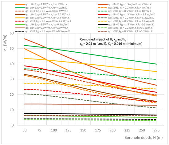
Figure 9.
Combined effect of borehole depth and soil and grout thermal conductivities on the heat transfer rate per unit borehole depth in the sBHE and the dBHE for the case of a small borehole size (rb = 0.05 m) with minimum shank spacing (Xc = 0.016 m).
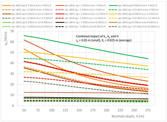
Figure 10.
Combined effect of borehole depth and soil and grout thermal conductivities on the heat transfer rate per unit borehole depth in the sBHE and the dBHE for the case of a small borehole size (rb = 0.05 m) with average shank spacing (Xc = 0.025 m).
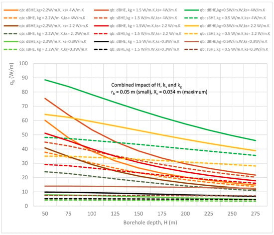
Figure 11.
Combined effect of borehole depth and soil and grout thermal conductivities on the heat transfer rate per unit borehole depth in the sBHE and the dBHE for the case of a small borehole size (rb = 0.05 m) with maximum shank spacing (Xc = 0.034 m).
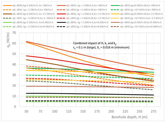
Figure 12.
Combined effect of borehole depth and soil and grout thermal conductivities on the heat transfer rate per unit borehole depth in the sBHE and the dBHE for the case of largest borehole size (rb = 0.1 m) with minimum shank spacing (Xc = 0.016 m).
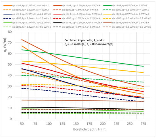
Figure 13.
Combined effect of borehole depth and soil and grout thermal conductivities on the heat transfer rate per unit borehole depth in the sBHE and the dBHE for the case of the largest borehole size (rb = 0.1 m) with average/medium shank spacing (Xc = 0.05 m).
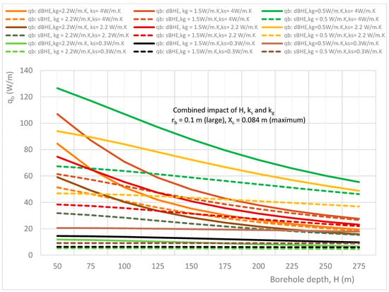
Figure 14.
Combined effect of borehole depth and soil and grout thermal conductivity on the heat transfer rate per unit borehole depth in the sBHE and the dBHE for the case of the largest borehole size (rb = 0.1 m) with minimum shank spacing (Xc = 0.084 m).
Figure 9, Figure 10 and Figure 11 illustrate the combined impact of borehole depth and soil and grout thermal conductivities on the heat transfer rate per unit borehole depth in both the sBHE and the dBHE for the case of a small borehole size (rb = 0.05 m) with minimum half shank spacing (Xc = 0.016 m), average half shank spacing (Xc = 0.025 m), maximum half shank spacing (Xc = 0.034 m), respectively. It can be observed that the dBHE with minimum (low) grout thermal conductivity (kg = 0.5 W/m∙K) and high soil thermal conductivity provides more heat transfer than the three other cases shown in Figure 9, Figure 10 and Figure 11; a similar result is obtained for the sBHE. A comparison among Figure 9, Figure 10 and Figure 11 shows that more heat transfer is achieved by the BHE with maximum shank spacing (Xc = 0.034 m) depicted in Figure 9 (see case 3 in column B of Table 3). This is because when the U-tube legs are widely spaced, the phenomenon of thermal short-circuit between the legs of the U-tube is reduced and the surface area is increased, resulting in more heat transfer between the working fluid in the BHE and the ground around the BHE. Furthermore, the results depicted in Figure 9, Figure 10 and Figure 11 show that in some cases, sBHEs are preferable to transfer more heat than dBHEs, specially for deep borehole depths. For example, the sBHE with minimum grout thermal conductivity (kg = 0.5 W/m∙K) and maximum soil thermal conductivity (ks = 4 W/m∙K) transferred more heat than for most of the cases of the dBHE. The reason for this is associated with the reduced thermal interference between the legs of the sBHE, as compared with the dBHE, and the low grout thermal conductivity, resulting in more heat transfer to the ground. Therefore, the low grout thermal conductivity and high soil thermal conductivity case is preferred to transfer more heat to the ground in the BHE. At a longer borehole depth, the sBHE is better able to transfer more heat than the dBHE; while for the BHE with a shallow borehole depth, the dBHE is able to transfer more heat than the sBHE.
The results shown in Figure 12, Figure 13 and Figure 14 illustrate the combined impact of borehole depth, grout, and soil thermal conductivity on the heat transfer rate per unit borehole depth in the sBHE and the dBHE for a large borehole size (rb = 0.1 m) with minimum shank spacing (Xc = 0.016 m), average shank spacing (Xc = 0.05 m), and maximum shank spacing (Xc = 0.084 m), respectively. The results depicted in Figure 12 illustrate the case of a large borehole size with minimum shank spacing; it can be seen that the dBHE filled with grout with kg = 1.5 W/m∙K and installed at ground level with high soil thermal conductivity (ks = 4 W/m∙K) provides the highest heat transfer. However, for a longer borehole depth beyond 275 m, the dBHE with low grout thermal conductivity (kg = 0.5 W/m∙K) and high soil thermal conductivity (ks = 4 W/m∙K) seems to provide more heat transfer than the other cases considered in Figure 12. This is more clearly observed in Figure 14, where the dBHE with maximum shank spacing, with kg = 0.5 W/m∙K and ks = 4 W/m∙K, provides the highest heat transfer all along the borehole depth.
On the other hand, Figure 13 shows that the dBHE with average shank spacing, average grout thermal conductivity, and high soil thermal conductivity provides the most heat transfer when used at a shorter borehole depth; but the dBHE filled with grout with minimum thermal conductivity and high soil thermal conductivity is preferable to transfer more heat into the ground when applied at a deeper borehole depth. Similarly, Figure 13 indicates that the sBHE with average shank spacing, low (minimum) grout thermal conductivity, and high soil thermal conductivity is preferred to deliver more heat transfer into the ground when applied at a deep borehole depth.
Overall, the comparison of the results depicted in Figure 9, Figure 10, Figure 11, Figure 12, Figure 13 and Figure 14 shows that among the nine cases listed in column B of Table 3, case 9 (depicted in Figure 14) provides the highest heat transfer per unit borehole depth. Of all the cases, the dBHE with a large borehole size, maximum shank spacing, low grout thermal conductivity, and high soil thermal conductivity is the most effective at transferring more heat, especially for a borehole with a shallow borehole depth, than any of the other cases. For a borehole with a deep borehole depth, the sBHE with the same design condition is preferred. Similar important information that can be used as a quick reference for the design of a BHE can be deduced or obtained from the generated results depicted in the other figures.
- C.
- Combined Effect of Borehole Size and the Thermal Conductivities of Soil and Grout
The thermal conductivity of the ground around a BHE and the backfill material are among the parameters that affect heat transfer in a BHE. The higher the soil thermal conductivity, the higher the heat transfer between the ground and the fluid that circulates in the loop between the BHE and the heat pump. This results in increased performance of the ground source heat pump system (GSHP), and hence, leads to a reduced total cost of the power consumed by the GSHP system. Grout thermal conductivity is another thermal parameter that impacts heat transfer in a BHE. Backfill material with high thermal conductivity is considered to enhance the heat transfer in a BHE, and hence improves the efficiency of a BHE. However, excessive thermal conductivity of grout may increase thermal short-circuit between U-tube pipes, leading to reduced thermal performance of a BHE. As seen in the previous cases A and B, high grout thermal conductivity reduces the heat transfer in the BHE particularly for the dBHE with a deep borehole depth and small shank spacing.
Changing (increasing/reducing) one parameter alone cannot help to improve the thermal performance of a BHE. For example, increasing the thermal conductivity of grout or soil alone may not help to improve the heat transfer in a BHE. Hence, a sensitivity analysis consisting different combination of borehole parameters and thermal properties must be performed. That is, a detailed investigation involving the combined effect of parameters (for example, grout thermal conductivity with other parameters such as soil thermal conductivity and other borehole geometrical parameters) should be performed. Presenting such a comprehensive sensitivity analysis in graphical/tabular form conveniently helps a BHE designer to select the case that provides the highest heat transfer. That is, such results can be used as a quick reference for the design and optimization of a BHE.
In this subsection, the combined impact of the thermal conductivity of grout and soil as well as borehole size on heat transfer per unit borehole depth of the sBHE and the dBHE for different cases of borehole depth and shank spacing is discussed. This case is important as a quick reference for the design of a BHE with the given different cases of borehole depth and shank spacing that is desired to be installed at ground level with a known value of thermal conductivity. Then, one can select the BHE case that provides the highest heat transfer among the various cases of the sBHE and the dBHE presented in column C of Table 1.
The simulation results of the nine different cases considered in this section, shown in column C of Table 3, are depicted in Figure 15, Figure 16, Figure 17, Figure 18, Figure 19 and Figure 20. Various types of important information can be obtained from these results. An essential type of BHE design information can be obtained from these simulation results. For example, if a BHE (with a shallow/deep borehole depth and a given shank spacing) that can provide the highest amount of heat transfer is required to be installed at ground level with a certain thermal conductivity, then such information can be obtained from the results presented this section.
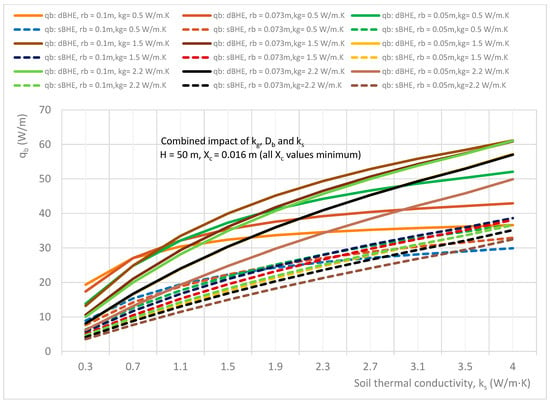
Figure 15.
Combined effect of soil thermal conductivity, grout thermal conductivity, and borehole size on the heat transfer rate per unit borehole depth in the sBHE and the dBHE for the case of a shallow borehole depth (H = 50 m) and all borehole sizes with the corresponding minimum shank spacing (rb = 0.1 m with Xc = 0.016 m; rb = 0.073 m with Xc = 0.016 m; and rb = 0.05 m with Xc = 0.016 m).
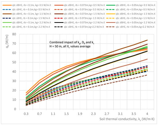
Figure 16.
Combined effect of soil thermal conductivity, grout thermal conductivity, and borehole size on the heat transfer rate per unit borehole depth in the sBHE and the dBHE for the case of a shallow borehole depth (H = 50 m) and all borehole sizes with corresponding average shank spacing (rb = 0.1 m with Xc = 0.05 m; rb = 0.073 m with Xc = 0.037 m; and rb = 0.05 m with Xc = 0.025 m).
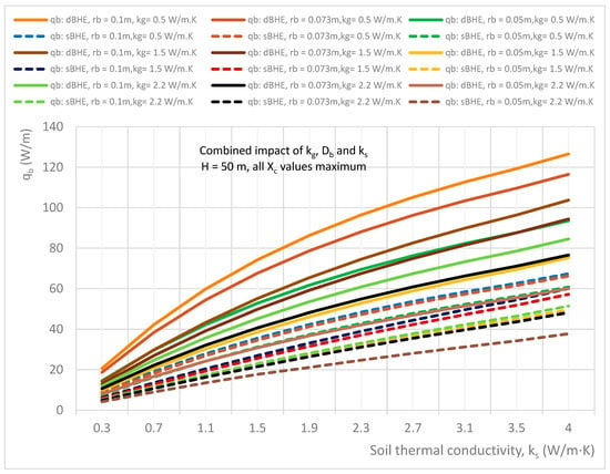
Figure 17.
Combined effect of soil thermal conductivity, grout thermal conductivity, and borehole size on the heat transfer rate per unit borehole depth in the sBHE and the dBHE for the case of a shallow borehole depth (H = 50 m) and all borehole sizes with corresponding maximum shank spacing (rb = 0.1 m with Xc = 0.084 m; rb = 0.073 m with Xc = 0.057 m; and rb = 0.05 m with Xc = 0.034 m).
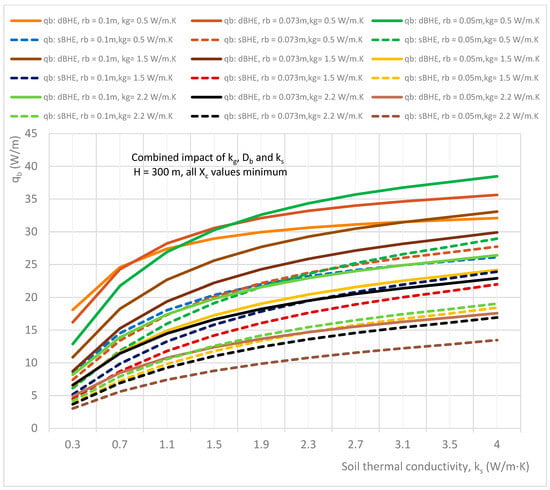
Figure 18.
Combined effect of soil thermal conductivity, grout thermal conductivity, and borehole size on the heat transfer rate per unit borehole depth in the sBHE and the dBHE for the case of a deep borehole depth (H = 300 m) and all borehole sizes with the corresponding minimum shank spacing (rb = 0.1 m with Xc = 0.016 m; rb = 0.073 m with Xc = 0.016 m; and rb = 0.05 m with Xc = 0.016 m).
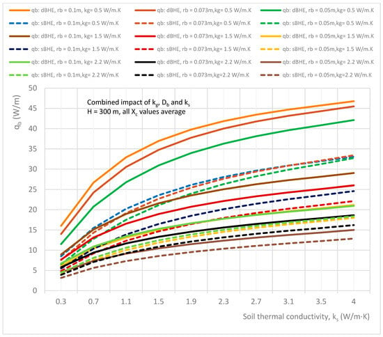
Figure 19.
Combined effect of soil thermal conductivity, grout thermal conductivity, and borehole size on the heat transfer rate per unit borehole depth in the sBHE and the dBHE for the case of a deep borehole depth (H = 300 m) and all borehole sizes with corresponding average shank spacing (rb = 0.1 m with Xc = 0.05 m; rb = 0.073 m with Xc = 0.037 m; and rb = 0.05 m with Xc = 0.025 m).
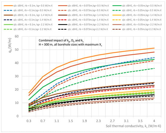
Figure 20.
Combined effect of soil thermal conductivity, grout thermal conductivity, and borehole size on the heat transfer rate per unit borehole depth in the sBHE and the dBHE for the case of a deep borehole depth (H = 300 m) and all borehole sizes with corresponding maximum shank spacing (rb = 0.1 m with Xc = 0.084 m; rb = 0.073 m with Xc = 0.057 m; and rb = 0.05 m with Xc = 0.034 m).
Nine different cases (listed in Table 3 in column C) consisting of a BHE with a shallow borehole depth (H = 50 m) and a deep borehole depth (H = 300 m) each with small, medium, and large borehole sizes (diameters) with corresponding minimum, average, and maximum shank spacing are analyzed. The simulation results of the combined impact of the thermal conductivities of grout and soil as well as borehole size on heat transfer per unit borehole depth for the sBHE and the dBHE with different cases of borehole depth and shank spacing are shown in Figure 15, Figure 16, Figure 17, Figure 18, Figure 19 and Figure 20. More specifically, the results presented in Figure 15, Figure 16, Figure 17, Figure 18, Figure 19 and Figure 20 provide important information on how to select a BHE that provides the highest heat transfer among the BHE design options (the sBHE and the dBHE with small, medium, and large borehole sizes with minimum, average, and maximum thermal conductivities of grout) for a given soil thermal conductivity, borehole depth (H = 50 m, and H = 300 m), and shank spacing. Note that each BHE is provided with the corresponding minimum, average, and maximum shank spacing.
The results depicted in Figure 15, Figure 16 and Figure 17 illustrate the results of the cases for a shallow borehole depth (H = 50 m) with all borehole sizes with the corresponding minimum shank spacing (rb = 0.1 m with Xc = 0.016 m; rb = 0.073 m with Xc = 0.016 m; and rb = 0.05 m with Xc = 0.016 m); all borehole sizes with corresponding average shank spacing (rb = 0.1 m with Xc = 0.05 m; rb = 0.073 m with Xc = 0.037 m; and rb = 0.05 m with Xc = 0.025 m); and all borehole sizes with the corresponding maximum shank spacing (rb = 0.1 m with Xc = 0.084 m; rb = 0.073 m with Xc = 0.057 m; and rb = 0.05 m with Xc = 0.034 m), respectively. It can be seen in Figure 15 that the dBHE with a large borehole size (rb = 0.1 m) and average grout thermal conductivity (kg = 1.5 W/m∙K) provides the highest heat transfer when the soil thermal conductivity is higher than 1 W/m∙K. For soil thermal conductivity lower than about 1 W/m∙K, the dBHE with a large borehole size (rb = 0.1 m) and low grout thermal conductivity (kg = 0.5 W/m∙K) provides the highest heat transfer, while its heat transfer for high soil thermal conductivity is lower than the other cases (and lower than even some cases of the sBHE). This could be attributed to the greater thermal short-circuit associated with a BHE with minimum shank spacing.
Figure 16 shows the combined effect of soil thermal conductivity, grout thermal conductivity and borehole size on the heat transfer rate per unit borehole depth in the sBHE and the dBHE for the case of a shallow borehole depth (50 m) and all borehole sizes with the corresponding average shank spacing (rb = 0.1 m with Xc = 0.05 m; rb = 0.073 m with Xc = 0.037 m; and rb = 0.05 m with Xc = 0.025 m). For a soil thermal conductivity lower than 2.3 W/m∙K, the dBHE with a large borehole size (rb = 0.1 m) and low (minimum) grout thermal conductivity (kg = 0.5 W/m∙K) provides the highest heat transfer, while for a soil thermal conductivity higher than 2.3 W/m∙K, the dBHE with a large borehole size (rb = 0.1 m) filled with grout with average thermal conductivity (kg = 1.5 W/m∙K) results in the highest heat transfer of all the cases presented in Figure 16. It is also important to note that the dBHE with rb = 0.05 m and maximum grout thermal conductivity (kg = 2.2 W/m∙K) provides the lowest heat transfer of all the cases of the dBHE considered in Figure 16. As depicted in Figure 17, when the BHE with the corresponding maximum shank spacing is applied in each borehole size, it is observed that the dBHE with a large borehole size (rb = 0.1 m) and low (minimum) grout thermal conductivity (kg = 0.5 W/m∙K) provides a higher heat transfer for the whole range of soil thermal conductivities (0.3 to 4 W/m∙K) than the other cases of the BHE considered under this case. A close look at Figure 17 also shows that the dBHE with an average borehole size (rb = 0.073 m) and low grout thermal conductivity (kg = 0.5 W/m∙K) delivers more heat transfer than even the dBHE with a large borehole size (rb = 0.1 m) and average (kg = 1.5 W/m∙K) and maximum grout thermal conductivities (kg = 2.2 W/m∙K). This could be attributed to the greater thermal short-circuit associated with high grout thermal conductivity. This indicates that a greater impact on heat transfer is observed with reduced grout thermal conductivity combined with increased borehole size than a combined increase in borehole size and grout thermal conductivity. Therefore, when a BHE with maximum shank spacing is used, more heat transfer can be achieved by the combined increase in borehole size and reduced grout thermal conductivity. Finally, a comparison among Figure 15, Figure 16 and Figure 17 shows that more heat transfer is obtained for the case with maximum shank spacing (shown in Figure 17), and in all the cases shown in these figures, the dBHE is better able to transfer more heat than the corresponding sBHE.
A further analysis was performed for the case considered in column C in Table 3 for the BHE with a deep borehole depth (H = 300 m), and the simulation results obtained for this case are presented in Figure 18, Figure 19 and Figure 20. Figure 18 shows the combined impact of soil and grout thermal conductivities as well as borehole size on heat transfer per unit borehole depth for BHEs with corresponding minimum shank spacing, while Figure 19 and Figure 20 show the combined effect of parameters on heat transfer for the BHEs with the corresponding average and maximum shank spacing, respectively. It can be seen in Figure 18 that for the BHE with a deep borehole depth and minimum shank spacing, the heat transferred by the dBHE with a small borehole size (rb = 0.05 m) and minimum grout thermal conductivity is the highest for the soil with thermal conductivity higher than 1.7 W/m∙K, and for soil thermal conductivity lower than 0.7 W/m∙K, the dBHE with a large borehole size and low grout thermal conductivity is preferred. This clearly indicates that for the BHE with minimum shank spacing and a deep borehole depth, using a BHE with a large borehole size and with high grout and soil thermal conductivity is not preferred for transferring more heat between the working fluid and the ground around the BHE. This could be due to the augmented phenomenon of thermal short-circuit between the legs of the BHE designed with minimum shank spacing, a large borehole, and filled with grout that has high thermal conductivity. On the other hand, for borehole heat exchangers (BHEs) with corresponding average and maximum shank spacing (shown in Figure 19 and Figure 20, respectively), the dBHE with a large borehole size and low grout thermal conductivity provides the highest heat transfer for the whole range of soil thermal conductivities considered in this study (0.3 to 4 W/m∙K). This indicates that if a BHE with a deep borehole depth is required to be designed to deliver the highest heat transfer rate per unit borehole depth, then a dBHE with a large borehole diameter, maximum shank spacing, and low grout thermal conductivity is preferred for the entire range of the ground thermal conductivities. A close look at Figure 20 indicates that for a BHE designed with maximum shank spacing, a deep borehole depth, low grout thermal conductivity, and high soil thermal conductivity, a sBHE with a large borehole size can provide more heat transfer than a dBHE with a small borehole size. Finally, a comparison of the results presented in Figure 18 and Figure 20 indicates that for the same borehole depth, borehole size, and grout thermal conductivity, the heat transferred by the BHE with high shank spacing is higher than that of the BHE with low shank spacing.
Overall, a comparison among the nine cases (listed in column C of Table 3 and depicted in Figure 15, Figure 16, Figure 17, Figure 18, Figure 19 and Figure 20) shows that the third case (presented in Figure 17) provided the highest heat transfer. Furthermore, the results presented in Figure 15, Figure 16, Figure 17, Figure 18, Figure 19 and Figure 20 reveal that the dBHE provides more heat transfer when used at a shallow borehole depth, while the sBHE is preferred to transfer more heat when applied at a deep borehole depth. The reason for this (as stated in the previous section) is because there is more thermal interference in the dBHE than in the sBHE when applied in a deep BHE. To reduce the impact of the thermal loss (due to thermal short-circuit or thermal interference) associated with a BHE with a deep borehole depth, utilizing a large borehole diameter and low grout thermal conductivity could be among the design options that can be considered.
- D.
- Combined Effect of Soil Thermal Conductivity, Borehole Size, and Shank Spacing
In this subsection, the combined impact of soil thermal conductivity, borehole size (diameter), and shank spacing on the heat transfer rate per unit borehole depth in the sBHE and the dBHE for different cases of grout thermal conductivity (minimum, kg = 0.5 W/m∙K; average, kg = 1.5 W/m∙K; and maximum, kg = 2.2 W/m∙K) and borehole depth (shallow borehole depth, H = 50 m; average borehole depth, H = 100 m; and deep borehole depth, H = 300 m). The simulation results generated in this subsection have different cases (listed in Table 3 in column D and presented in Figure 21, Figure 22, Figure 23, Figure 24, Figure 25 and Figure 26). This case is important as a quick reference for the design of a BHE with a given borehole depth and grout thermal conductivity that is desired to be installed at ground level with a known (experimentally determined) value of soil thermal conductivity. Specifically, the results presented in Figure 21, Figure 22, Figure 23, Figure 24, Figure 25 and Figure 26 provide important information on how to select a BHE that provides the highest heat transfer among the BHE design options (sBHEs and dBHEs with small, medium, and large borehole sizes, each of them having the corresponding minimum, average, and maximum shank spacing) for a given soil thermal conductivity, borehole depth (H = 50 m, H = 100 m and H = 300 m), and grout thermal conductivity (kg = 0.5 W/m∙K (minimum); 1.5 W/m∙K (average); and 2.2 W/m∙K (maximum)). An important type of BHE design information can be read/obtained from these simulation results. For example, if a BHE (with a shallow/deep borehole depth and a given grout thermal conductivity) that can provide the highest heat transfer is required to be installed at ground level with a certain soil thermal conductivity, reference information suitable for the design of such a BHE configuration can be obtained from results presented in Figure 21, Figure 22, Figure 23, Figure 24, Figure 25 and Figure 26.
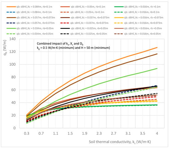
Figure 21.
Combined effect of soil thermal conductivity, shank spacing, and borehole size on the heat transfer rate per unit borehole depth in the sBHE and the dBHE for the case of minimum grout thermal conductivity (kg = 0.5 W/m∙K) with a shallow borehole depth (H = 50 m).
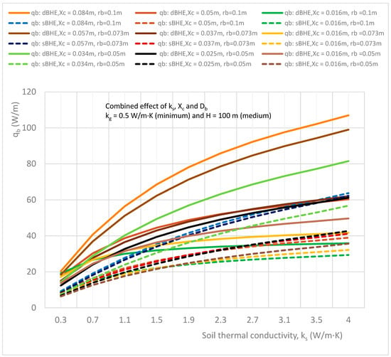
Figure 22.
Combined effect of soil thermal conductivity, shank spacing, and borehole size on the heat transfer rate per unit borehole depth in the sBHE and the dBHE for the case of minimum grout thermal conductivity (kg = 0.5 W/m∙K) with an average borehole depth (H = 100 m).
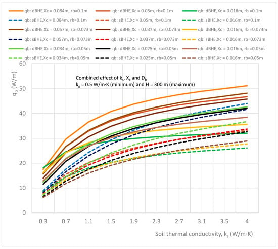
Figure 23.
Combined effect of soil thermal conductivity, shank spacing, and borehole size on the heat transfer rate per unit borehole depth in the sBHE and the dBHE for the case of minimum grout thermal conductivity (kg = 0.5 W/m∙K) with a high borehole depth (H = 300 m).
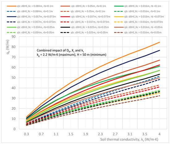
Figure 24.
Combined effect of soil thermal conductivity, shank spacing, and borehole size on the heat transfer rate per unit borehole depth in the sBHE and the dBHE for the case of maximum grout thermal conductivity (kg = 2.2 W/m∙K) with a shallow borehole depth (H = 50 m).
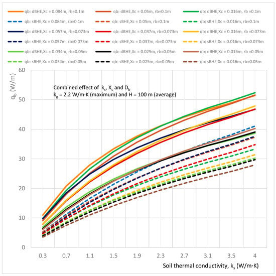
Figure 25.
Combined effect of soil thermal conductivity, shank spacing, and borehole size on the heat transfer rate per unit borehole depth in the sBHE and the dBHE for the case of maximum grout thermal conductivity (kg = 2.2 W/m∙K) with a medium borehole depth (H = 100 m).
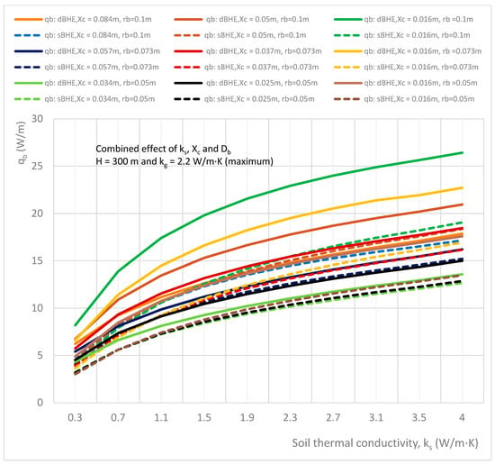
Figure 26.
Combined effect of soil thermal conductivity, shank spacing, and borehole size on the heat transfer rate per unit borehole depth in the sBHE and the dBHE for the case of maximum grout thermal conductivity (kg = 2.2 W/m∙K) with a deep borehole depth (H = 300 m).
The results presented in Figure 21, Figure 22 and Figure 23 indicate the combined impact of soil thermal conductivity, borehole size, and shank spacing on the heat transfer rate in both the sBHE and the dBHE filled with grout with minimum thermal conductivity (kg = 0.5 W/m∙K) combined with a shallow borehole depth (H = 50 m), average borehole depth (H = 100 m), and deep borehole depth (H = 300 m), respectively. Valuable BHE design information can be obtained from these simulation results. For instance, Figure 21, Figure 22 and Figure 23 show that the dBHE with a large borehole size (rb = 0.1 m) and maximum shank spacing (Xc = 0.084 m) provides the highest heat transfer for the whole range of soil of thermal conductivities considered in this study (0.3 to 4 W/m∙K). It is followed by the dBHE with medium and small borehole sizes, each with the corresponding maximum shank spacing. In addition, Figure 20 and Figure 21 show that in the ground with high soil thermal conductivity (higher than 3.5 W/m∙K), the sBHE with a large borehole size (rb = 0.1 m) and maximum shank spacing (Xc = 0.084 m) provides more heat transfer than even the dBHE with a medium size (rb = 0.073 m) and maximum shank spacing as well as the dBHE with a small borehole size (rb = 0.05 m) and maximum shank spacing (Xc = 0.034 m). However, for low ground thermal conductivity (lower than 3.5 W/m∙K), the dBHE provides more heat transfer than the corresponding sBHE. Furthermore, Figure 21, Figure 22 and Figure 23 show that increasing shank spacing has more impact on the heat transfer of the dBHE than the corresponding sBHE, and this impact on heat transfer becomes higher for the ground with high soil thermal conductivity. The results depicted in Figure 21, Figure 22 and Figure 23 show that the impact of increasing borehole size and shank spacing is less effective for the sBHE (as compared with the corresponding dBHE), especially for the case of the BHE with a deep borehole depth (H = 300 m) shown in Figure 23. Moreover, a comparison among Figure 21, Figure 22 and Figure 23 shows that case 1 (depicted in Figure 21) provides a higher transfer than the second and third cases (presented in Figure 22 and Figure 23 and listed in column D of Table 3).
The results presented in Figure 24, Figure 25 and Figure 26 illustrate the combined impact of soil thermal conductivity, borehole size, and shank spacing on the heat transfer rate per unit borehole depth in the sBHE and the dBHE for the case of grout with maximum thermal conductivity (kg = 2.2 W/m∙K), a borehole with a shallow borehole depth (H = 50 m), an average borehole depth (H = 100 m), and a deep borehole depth (H = 300 m), respectively. The simulation results reveal that the heat transfer per unit borehole depth for these cases (with maximum grout thermal conductivity), as indicated in Figure 24, Figure 25 and Figure 26, are the lowest compared with the corresponding heat transfer values obtained for the remaining cases considered Table 3 in column D. The reduction in heat transfer of the BHE in these cases could be due to the thermal short-circuit associated with grout with high/maximum thermal conductivity. The impact of this thermal interference between the legs of the BHE becomes more amplified in the BHE with a deep borehole depth, as presented in Figure 26, and hence, the heat transfer per unit borehole depth is further reduced and become the lowest compared with all the other cases considered in column D of Table 3 (Figure 24, Figure 25 and Figure 26).
3.2. Impact of the Convection Heat Transfer Coefficient and Flow Regime on Heat Transfer in the BHE
The total heat transfer between the working fluid in the BHE and the soil/ground predominantly consists of convection and conduction heat transfer. The convection heat transfer, which occurs between the fluid and U-tube pipe wall, is a strong function of the convection heat transfer coefficient (hf), which in turn depends on several factors such as velocity, surface area, type of geometry, friction factor, flow regime, etc.
In this section, the impact of the convection heat transfer coefficient (hf) and flow regime on the total heat transfer from the working fluid to the ground around the BHE is discussed. In order to investigate the impact of increasing the convection heat transfer coefficient on total heat transfer, the double U-tube BHE (dBHE) with different borehole sizes (small, medium, and large borehole sizes), which are indicated in Table 4, Table 5 and Table 6, was considered, respectively. The U-tube pipe used in all the three borehole sizes is HDPE (with a pipe thermal conductivity of 0.4 W/m∙K, an outside diameter of 32 mm, and an inside diameter of 28 mm). To study the impact, the convection heat transfer coefficient of each flow regime (laminar and turbulent) was artificially increased by multiplying the calculated corresponding heat transfer coefficient by a factor of 2, as shown in Table 4, Table 5 and Table 6. For example, for laminar flow and turbulent flow of a small-sized BHE (Table 4), the calculated hf values were 77.7 and 916.2 W/m2∙K, respectively.

Table 4.
The impact of the convection heat transfer coefficient (hf) on the total heat transfer rate of the dBHE with a small borehole size (rb = 0.05 m, Xc = 0.025 m, kg = 0.5 W/m∙K, H = 25 m, Tf,in = 15 °C).

Table 5.
The impact of the convection heat transfer coefficient on the total heat transfer rate of the dBHE with medium borehole size (rb = 0.07 m, Xc = 0.035 m, kg = 1.3 W/m∙K, H = 125 m, Tf,in = 27 °C).

Table 6.
The impact of the convection heat transfer coefficient (hf) on the total heat transfer rate of the dBHE with large borehole size (rb = 0.1 m, Xc = 0.05 m, kg = 2.5 W/m∙K, H = 250 m, Tf,in = 42 °C).
The simulation results reveal that increasing the convection heat transfer coefficient by 100%, with the mass flow rate kept constant, has an insignificant impact on the total heat transfer per unit borehole depth in both the laminar and turbulent flows. For the smaller borehole size (shown in Table 4), the average improvements in heat transfer per borehole depth (due to an increase in hf of 100%) for the laminar and turbulent flows are only 0.44 W/m (5.4%) and 0.07 W/m (0.61%), respectively. For the larger borehole size (rb = 0.1 m, Table 6), the corresponding average improvements in heat transfer in the laminar and turbulent flows are 0.33 W/m (8.9%) and 0.2 W/m (0.59%), respectively. Thus, when the mass flow rate is kept fixed and the convective heat transfer coefficient is artificially increased even by 100%, the increase in heat transfer is negligible, particularly when the flow is turbulent. Based on this result, there is no benefit in increasing the internal convective heat transfer coefficient on the improvement in the overall heat transfer in the BHE. Furthermore, the results presented in Table 4, Table 5 and Table 6 show that the heat transfer rate is highest in the turbulent flow regime. This increase in the total heat transfer for turbulent flow could be due to the convective heat transfer coefficient of the convective heat transfer between the fluid and the pipe surface.
An analysis was also performed to investigate the impact of flow regimes on the total heat transfer in the BHE. To generate the heat transfer profiles in different flow regimes (shown in Figure 27 and Figure 28), the input values of the fixed parameters in the model were specified as follows: borehole radius, rb = 0.1 m; half shank spacing, Xc = 0.05 m; grout thermal conductivity, kg = 1.5 W/m∙K; borehole depth, H = 100 m; Tf,in = 40 °C; undisturbed ground temperature, To = 10 °C; pipe thermal conductivity, kp = 0.4 W/m∙K; outer pipe diameter, 32 mm; and inner pipe diameter, 28 mm. The input values of the other fixed parameters of the thermal properties of the fluid (water), backfill material, and soil are listed in Table 2. Figure 27 illustrates the variation in the total heat transfer in the laminar, transitional, and turbulent flows in the dBHE at different values of soil thermal conductivity. The profile of the total heat transfer in different flow regimes of the sBHE is presented in Figure 28. Looking at Figure 27 and Figure 28, there is a significant difference in the heat transfer profile in between the laminar and turbulent flows. The heat transfer in the laminar flow is lower and increases linearly with the mass flow rate, while it becomes higher and increases nonlinearly in the turbulent flow. When the mass flow rate is too high, the fluid temperature will change slowly along the U-tube, and hence, keep the larger temperature difference between the fluid and the ground for a longer period, resulting in higher heat transfer in the turbulent flow. The reverse is true for the laminar flow with a lower mass flow rate, resulting in lower heat transfer. In Figure 27 and Figure 28, it is also interesting to note that with a further increase in the mass flow rate, the heat transfer profile in the turbulent flow tends to reach a plateau (i.e., the increase in heat transfer is insignificant). Moreover, the improvement in the heat transfer from the laminar to turbulent flow regime is greatest when the soil thermal conductivity is highest (in this case, at ks = 4 W/m∙K).
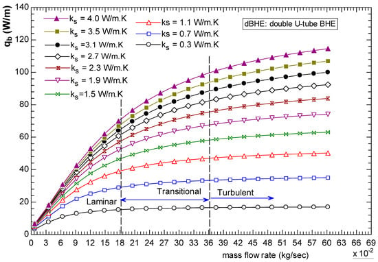
Figure 27.
Profile of the total heat transfer rate per unit borehole depth in different flow regimes in the double U-tube BHE.
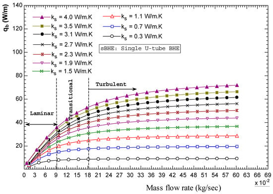
Figure 28.
Profile of the total heat transfer per unit borehole depth in different flow regimes in the single U-tube BHE.
Finally, if one wants to have a laminar flow for reducing pumping power, it may be beneficial to use a nanofluid to enhance heat transfer, provided that the nanofluid does not have a high viscosity. However, if the flow is already turbulent, using a nanofluid is a waste of money. In addition, in the turbulent flow, when mass flow rate is too high, the associated operational energy consumption becomes higher without an improvement in the total heat transfer since the increased pressure loss causes an increased in flow resistance, resulting in reduced overall heat exchange performance.
3.3. Pumping Power and Pressure Loss in the BHE
Another crucial feature that is required in the design of a BHE is the pumping power, which is required to circulate the working fluid in the closed loop of the BHE. Particularly, in the BHE with a deep borehole, high pressure loss and head loss is incurred, resulting in a high pumping energy consumption to circulate the working fluid. The pumping energy consumption is directly related to the total cost of the ground source heat pump system that delivers space heating and cooling. As a result, including an analysis of the pumping power and pressure loss or head loss in the performance analysis of BHEs is important.
In this paper, an analysis and comparison of pumping power and pressure loss as well as the head loss in the sBHE and the dBHE is performed. The variation in the pressure drop and head loss with the total mass flow rate of the working fluid (0.22 to 0.4 kg/s) for the sBHE and the dBHE with a borehole depth of 100 m and a U-tube pipe (made of HDPE with a kp of 0.4 W/m∙K, a 32 mm outside diameter, and a 28 mm inner diameter) is illustrated in Figure 29. The comparison results indicate that the total pressure drop and head loss in the sBHE is higher than those in the dBHE, leading to higher pump power consumption. Accordingly, as evidenced in Figure 30, for the same operating conditions, the corresponding circulating pump power is more when the sBHE is utilized than that when the dBHE is utilized. At a flow rate of 0.22 kg/s, the pumping power of the sBHE is 1.21 W more than that of the dBHE. Furthermore, the difference in pumping power between the sBHE and the dBHE reaches about 6.36 W when the fluid flow rate is increased to 0.4 kg/s. Therefore, based on this analysis, to reduce the pressure drop to a reasonable range (and hence, reduce the required pumping energy consumption), it is better to utilize the dBHE. But still, a further analysis that compares the total cost between the two BHEs needs be performed to select the configuration that consumes less power with a reasonable total cost along with improved thermal performance.
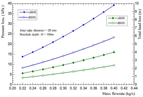
Figure 29.
Pressure and head losses in the single and double U-tube BHEs with a borehole depth of 100 m and an inner pipe diameter of 28 mm.
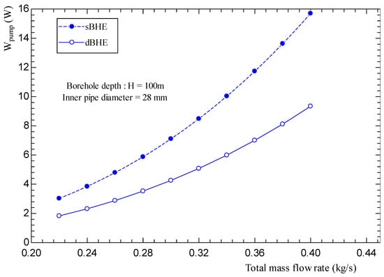
Figure 30.
Theoretical pumping power to circulate the working fluid in the single and double U-tube BHEs with a borehole depth of 100 m and an inner pipe diameter of 28 mm.
Furthermore, for a detail understanding of the pumping power consumption of a BHE, the pressure loss as a function of the borehole depth was analyzed. As indicated in Figure 31, the total pressure loss becomes higher as the borehole depth increases. This in turn leads to higher pumping power consumption for a longer borehole depth, as depicted in Figure 32. Hence, both the pressure loss and pumping power increase parabolically with the borehole depth; when the borehole length is from 100 m to 250 m, the pumping rate increases by 5.7 and 5.6 times for the sBHE and the dBHE, respectively. The corresponding pressure loss is raised by 3.7 and 3.6 times for the sBHE and the dBHE, respectively. This shows that the BHE with a shallow borehole depth and lower mass flow rate within a reasonable range of velocity is preferable since the BHE with large depth and mass flow rate results in high pressure loss and increased pumping power consumption.
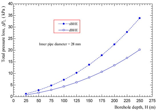
Figure 31.
Pressure drop variation with borehole depth for single and double U-tube BHEs with an HDPE pipe inner diameter of 28 mm.
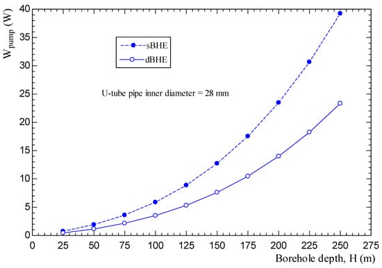
Figure 32.
Pumping power variation with borehole depth for single and double U-tubes made of an HDPE pipe (inner diameter of 28 mm).
Moreover, as can be inferred from Figure 29, Figure 30, Figure 31 and Figure 32, at all the borehole depths, both the pressure loss and pumping power of the sBHE is higher than that of the dBHE. A further comparative analysis also indicates that the difference in pressure drop and pumping power between the two BHEs becomes higher and higher with a further increase in the mass flow rate and borehole depth. For a borehole depth (H) of 25 m, the decrease in both the pressure loss and pumping power when the dBHE is utilized is 39.7%, whereas for a deep borehole depth of 250 m, if the dBHE configuration is used, then the pressure loss and pumping power are reduced by 40.5% and 38.6%, respectively.
4. Conclusions
In this paper, the combined effect of major influencing parameters that affect the performance of both single U-tube BHEs (sBHEs) and double U-tube BHEs (dBHEs) was numerically studied. Geometrical parameters, such as shank spacing and borehole size/diameter, borehole depth, and the thermal conductivities of soil and grout were considered. The combined impact of different parameters was included under the following four major cases: (A) the combined effect of borehole depth, borehole size, and shank spacing, (B) the combined effect of borehole depth and soil and grout thermal conductivities, (C) the combined effect of soil and grout thermal conductivities and borehole size, and (D) the combined effect of soil thermal conductivity, borehole size, and shank spacing. A series of heat transfer data in graphical form that helps to investigate the combined impact of various parameters on the heat transfer per unit borehole depth were generated. With the given parameters, one can select the BHE case that provides highest heat transfer among the various cases of the sBHE and the dBHE.
The key findings are recapped as followings:
- Among the cases considered under case A, the dBHE with a large borehole size, maximum shank spacing, minimum grout thermal conductivity, and maximum soil thermal conductivity provides the highest heat transfer per unit borehole depth, while the lowest heat transfer is obtained for case 7 (column A) with maximum grout thermal conductivity and low soil thermal conductivity.
- For a deep borehole depth with high grout thermal conductivity, the dBHE with a large borehole size and minimum shank spacing provides the highest heat transfer, while for a shallow borehole depth, the dBHE with large borehole size and maximum shank spacing is the most effective.
- When grout conductivity is low and soil thermal conductivity is at an average or high value, using a BHE with maximum shank spacing is effective in a large borehole size, while minimum shank spacing is more effective in a BHE with a small borehole size.
- Among the cases considered under case B, case 9 (see Table 3) provides the highest heat transfer per unit borehole depth. Of all the cases, the dBHE with a large borehole size, maximum shank spacing, low grout thermal conductivity, and high soil thermal conductivity is the most effective at transferring heat (especially for a borehole with a shallow borehole depth) than any of the other cases. For a borehole with a deep borehole depth, the sBHE with the same design conditions is preferred. This confirms the results obtained under case A.
- The comparison among the cases (listed in column C of Table 3) shows that the third case with a shallow borehole depth (H = 50 m) and all BHEs with maximum shank spacing provided the highest heat transfer per unit borehole depth, while the lowest heat transfer was obtained for the BHE with a deep borehole depth and all BHEs with minimum shank spacing.
- A dBHE is effective for a shallow borehole depth, while a sBHE is preferred for deep borehole depth because of thermal interference. To reduce the impact of the thermal loss due to thermal short-circuit associated with a BHE with a deep borehole depth, increasing the shank spacing, utilizing a large borehole diameter and low grout thermal conductivity could be among the design options that can be considered.
- A reduced grout thermal conductivity combined with an increased borehole size has a greater impact on heat transfer than the combined increase in borehole size and grout thermal conductivity. High grout thermal conductivity reduces heat transfer, particularly for the dBHE with a deep borehole depth and low shank spacing.
- For a BHE with minimum shank spacing and deep borehole depth, using a BHE with a large borehole size is not preferred to transfer more heat. This could be due to the augmented phenomenon of thermal short-circuit between the legs of the BHE with the minimum shank spacing and deep borehole depth.
- If a BHE with a deep borehole depth is required to be designed to deliver the highest heat transfer rate per unit borehole depth, then a dBHE with large borehole diameter, large shank spacing, low grout thermal conductivity, and high soil thermal conductivity is preferred.
- Increasing the internal convective heat transfer coefficient has a negligible impact on the improvement in the overall heat transfer in the BHE, particularly when the flow is turbulent. If one wants to have laminar flow for reducing pumping power, it may be beneficial to use a nanofluid to enhance heat transfer, provided that the nanofluid does not have a high viscosity.
- For the smaller borehole size (rb = 0.05 m), the average improvements in heat transfer per borehole depth (due to an increased hf of 100%) for the laminar and turbulent flows are only 0.44 W/m (5.4%) and 0.07 W/m (0.61%), respectively. For the larger borehole size (rb = 0.1 m), the corresponding average improvements in heat transfer in the laminar and turbulent flows are 0.33 W/m (8.9%) and 0.2 W/m (0.59%), respectively.
- The total pressure loss and pumping power required to circulate fluid in the sBHE is higher than that in the dBHE, and the total pressure loss and fluid pumping power increases parabolically with borehole depth.
- Pressure loss and pumping power increase parabolically with borehole depth; when the borehole length is increased from 100 m to 250 m, the pumping rate increases by 5.7 and 5.6 times for the sBHE and the dBHE, respectively. The corresponding pressure loss is raised by 3.7 and 3.6 times for the sBHE and the dBHE, respectively.
Overall, the obtained results can be used as a quick reference in the design and optimization of single and double U-tube BHEs that can be integrated with ground source heat pump systems.
Author Contributions
Conceptualization, A.S.F.; Methodology, E.D.K., A.S.F. and W.H.L.; Software, E.D.K.; Validation, E.D.K., A.S.F. and W.H.L.; Formal analysis, E.D.K., A.S.F. and W.H.L.; Investigation, E.D.K., A.S.F. and W.H.L.; Writing—original draft, E.D.K.; Writing—review & editing, A.S.F. and W.H.L.; Supervision, A.S.F.; Funding acquisition, A.S.F. All authors have read and agreed to the published version of the manuscript.
Funding
This research was funded by Natural Sciences and Engineering Research Council grant number RGPIN-2019-06853.
Data Availability Statement
The original contributions presented in the study are included in the article, further inquiries can be directed to the corresponding author.
Acknowledgments
The authors would like to acknowledge the Natural Sciences and Engineering Research Council (NSERC) of Canada Discovery Grant for their financial support of this research.
Conflicts of Interest
The authors declare no conflict of interest.
Nomenclature
| C | specific heat capacity (J/kg·K) |
| Xc | half of the shank spacing of a U-tube (m) |
| H | borehole depth (m) |
| h | heat transfer coefficient (W/m2·K) |
| fluid thermal conductivity (W/m·K) | |
| grout thermal conductivity (W/m·K) | |
| ground (soil) thermal conductivity (W/m·K) | |
| fluid mass flow rate (kg/s) | |
| mass of the fluid node (kg) | |
| mass of the grout node (kg) | |
| mass of the soil node (kg) | |
| heat transfer rate (W) | |
| total heat transfer rate into/out of the borehole per unit borehole depth (W/m) | |
| radius of the borehole (m) | |
| pipe outer radius (m) | |
| pipe inner radius (m) | |
| thermal resistance per unit length (m·K/W) | |
| Reynolds number | |
| T | temperature (°C) |
| fluid temperature (°C) | |
| inlet temperature of the working fluid in U-tube 1–3 (°C) | |
| inlet temperature of the fluid in U-tube 2–4 (°C) | |
| fluid temperature of down flow in U-tube 1–3 (°C) | |
| fluid temperature of upward flow in U-tube 1–3 (°C) | |
| fluid temperature of down flow in U-tube 2–4 (°C) | |
| fluid temperature of upward flow in U-tube 2–4 (°C) | |
| Temperature backfill material (grout) (°C) | |
| wall temperature of the borehole (°C) | |
| temperature of ground (soil) (°C) | |
| undisturbed ground temperature (°C) | |
| Greek Symbols | |
| vertical distance between adjacent nodes (m) | |
| duration of time step (s) | |
| density (kg/m3) | |
| thermal diffusivity (m2/s) | |
| dynamic viscosity (kg/m·s) | |
| thermal effectiveness | |
| Subscripts | |
| b | borehole |
| g | grout (backfill material) |
| f | fluid |
| s | ground (soil) |
References
- Florides, G.; Kalogirou, S. Ground heat exchangers: A review of systems, models and applications. Renew. Energy 2007, 32, 2461–2478. [Google Scholar] [CrossRef]
- Fang, L.; Diao, N.; Fang, Z.; Ke Zhu, K.; Zhang, W. Study on the efficiency of single and double U-tube heat exchangers. Procedia Eng. 2017, 205, 4045–4051. [Google Scholar] [CrossRef]
- Rosen, M.A.; Koohi-Fayegh, S. Geothermal Energy: Sustainable Heating and Cooling Using the Ground; John Wiley & Sons: Hoboken, NJ, USA, 2017. [Google Scholar]
- Florides, G.A.; Christodoulides, P.; Pouloupatis, P. Single and double U-tube ground heat exchangers in multiple-layer substrates. Appl. Energy 2013, 102, 364–373. [Google Scholar] [CrossRef]
- Molina-Giraldo, N.; Blum, P.; Zhu, K.; Bayer, P.; Fang, Z. A moving finite line source model to simulate borehole heat exchangers with groundwater advection. Int. J. Therm. Sci. 2011, 50, 2506–2513. [Google Scholar] [CrossRef]
- Jung, C.C.; Lee, S.R.; Lee, D.S. Numerical simulation of vertical ground heat exchangers: Intermittent operation in unsaturated soil conditions. Comput. Geotech. 2011, 38, 949–958. [Google Scholar]
- Luo, J.; Rohn, J.; Bayer, M.; Priess, A. Performance and economic evaluation of double U-tube borehole heat exchanger with three different borehole diameters. Energy Build. 2013, 67, 217–224. [Google Scholar] [CrossRef]
- Yang, W.; Zhang, S.; Chen, Y. A dynamic simulation method of ground coupled heat pump system based on borehole heat exchange effectiveness. Energy Build. 2014, 77, 17–27. [Google Scholar] [CrossRef]
- Hu, P.; Yub, Z.; Zhua, N.; Leia, F.; Yuan, X. Performance study of a ground heat exchanger based on the multipole theory heat transfer model. Energy Build. 2013, 65, 231–241. [Google Scholar] [CrossRef]
- Conti, P.; Testi, D.; Grassi, W. Revised heat transfer modeling of double-U vertical ground-couple heat exchangers. Appl. Therm. Eng. 2016, 106, 1257–1267. [Google Scholar] [CrossRef]
- Biglarian, H.; Abbaspour, M.; Saidi, M.H. A numerical model for transient simulation of borehole heat exchangers. Renew. Energy 2017, 104, 224–237. [Google Scholar] [CrossRef]
- Cao, S.; Kong, X.; Deng, Y.; Zhang, W.; Yang, L.; Ye, Z. Investigation on thermal performance of steel heat exchanger for ground source heat pump systems using full-scale experiments and numerical simulations. Appl. Therm. Eng. 2017, 115, 91–98. [Google Scholar] [CrossRef]
- Zhu, L.; Chen, S.; Yang, Y.; Sun, Y. Transient heat transfer performance of a vertical double U-tube borehole heat exchanger under different operation conditions. Renew. Energy 2019, 131, 494–505. [Google Scholar] [CrossRef]
- Kerme, E.D.; Fung, A.S. Heat transfer simulation, analysis and performance study of single U-tube borehole heat exchanger. Renew. Energy 2020, 145, 1430–1448. [Google Scholar] [CrossRef]
- Kerme, E.D.; Fung, A.S. Transient heat transfer simulation, analysis and thermal performance study of double U-tube borehole heat exchanger based on numerical heat transfer model. Appl. Therm. Eng. 2020, 173, 115189. [Google Scholar] [CrossRef]
- Zeng, H.; Diao, N.; Fang, Z. Heat transfer analysis of boreholes in vertical ground heat exchangers. Int. J. Heat Mass Transf. 2003, 46, 4467–4481. [Google Scholar] [CrossRef]
- Li, X.; Chen, Y.; Chen, Z.; Zhao, J. Thermal performances of different types of underground heat exchangers. Energy Build. 2006, 38, 543–547. [Google Scholar] [CrossRef]
- Gao, J.; Zhang, X.; Liu, J.; Li, K.S.; Yang, J. Thermal performance and ground temperature of vertical pile-foundation heat exchangers: A case study. Appl. Therm. Eng. 2008, 28, 2295–2304. [Google Scholar] [CrossRef]
- Pu, L.; Qi, D.; Li, K.; Tan, H.; Li, Y. Simulation study on the thermal performance of vertical U-tube heat exchangers for ground source heat pump system. Appl. Therm. Eng. 2015, 79, 202–213. [Google Scholar] [CrossRef]
- Zhang, C.; Chen, P.; Liu, Y.; Sun, S.; Peng, D. An improved evaluation method for thermal performance of borehole heat exchanger. Renew. Energy 2015, 77, 142–151. [Google Scholar] [CrossRef]
- Adamovský, D.; Neuberger, P.; Adamovský, R. Results of operational verification of vertical ground heat exchangers. Energy Build. 2017, 152, 185–193. [Google Scholar] [CrossRef]
- Sivasakthivel, T.; Philippe, M.; Murugesan, K.; Verma, V.; Hu, P. Experimental thermal performance analysis of ground heat exchangers for space heating and cooling applications. Renew. Energy 2017, 113, 1168–1181. [Google Scholar] [CrossRef]
- Qi, D.; Pu, L.; Ma, Z.; Xia, L.; Li, Y. Effects of ground heat exchangers with different connection configurations on the heating performance of GSHP systems. Geothermics 2019, 80, 20–30. [Google Scholar] [CrossRef]
- Jalaluddin, M.A.; Tsubaki, K.; Inoue, S.; Yoshida, K. Experimental study of several types of ground heat exchanger using a steel pile foundation. Renew. Energy 2011, 36, 764–771. [Google Scholar] [CrossRef]
- Makasis, N.; Narsilio, G.A.; Bidarmaghz, A.; Johnston, I.W. Ground-source heat pump systems: The effect of variable pipe separation in ground heat exchangers. Comput. Geotech. 2018, 100, 97–109. [Google Scholar] [CrossRef]
- Choi, W.; Kikumoto, H.; Ooka, R. Probabilistic uncertainty quantification of borehole thermal resistance in real-world scenarios. Energy 2022, 254, 124400. [Google Scholar] [CrossRef]
- Sandler, S.; Zajaczkowski, B.; Bialko, B.; Malecha, Z.M. Evaluation of the impact of the thermal shunt effect on the U-pipe ground borehole heat exchanger performance. Geothermics 2017, 65, 244–254. [Google Scholar] [CrossRef]
- Casasso, A.; Sethi, R. Efficiency of closed loop geothermal heat pumps: A sensitivity analysis. Renew. Energy 2014, 62, 737–746. [Google Scholar] [CrossRef]
- Minaei, A.; Maerefat, M. Thermal resistance capacity model for short-term borehole heat exchanger simulation with non-stiff ordinary differential equations. Geothermics 2017, 70, 260–270. [Google Scholar] [CrossRef]
- Tang, F.; Nowamooz, H. Factors influencing the performance of shallow Borehole Heat Exchanger. Energy Convers. Manag. 2019, 181, 571–583. [Google Scholar] [CrossRef]
- Zhang, C.; Wang, X.; Sun, P.; Kong, X.; Sun, S. Effect of depth and fluid flow rate on estimate for borehole thermal resistance of single U-pipe borehole heat exchanger. Renew. Energy 2020, 147, 2399–2408. [Google Scholar] [CrossRef]
- Jun, L.; Xu, Z.; Jun, G.; Jie, Y. Evaluation of heat exchange rate of GHE in geothermal heat pump systems. Renew. Energy 2009, 34, 2898–2904. [Google Scholar] [CrossRef]
- Chen, S.; Mao, J.; Han, X. Heat transfer analysis of a vertical ground heat exchanger using numerical simulation and multiple regression model. Energy Build. 2016, 129, 81–91. [Google Scholar] [CrossRef]
- Li, Y.; Mao, J.; Geng, S.; Han, X.; Zhang, H. Evaluation of thermal short-circuiting and influence on thermal response test for borehole heat exchanger. Geothermics 2014, 50, 136–147. [Google Scholar] [CrossRef]
- Zhai, X.Q.; Cheng, X.W.; Wang, R.Z. Heating and cooling performance of a mini type ground source heat pump system. Appl. Therm. Eng. 2017, 111, 1366–1370. [Google Scholar] [CrossRef]
- Zhang, W.; Yang, H.; Lu, L.; Fang, Z. Investigation on influential factors of engineering design of geothermal heat exchangers. Appl. Therm. Eng. 2015, 84, 310–319. [Google Scholar] [CrossRef]
- Zhou, H.; Lv, J.; Li, T. Applicability of the pipe structure and flow velocity of vertical ground heat exchanger for ground source heat pump. Energy Build. 2016, 117, 109–119. [Google Scholar] [CrossRef]
- Han, C.; Yu, X.B. Sensitivity analysis of a vertical geothermal heat pump system. Appl. Energy 2016, 170, 148–160. [Google Scholar] [CrossRef]
- Nellis, G.; Klien, S. Heat Transfer; Cambridge University Press: Cambridge, UK, 2009. [Google Scholar]
- Zeng, H.; Diao, N.; Fang, Z. Efficiency of vertical geothermal heat exchangers in the ground source heat pump system. J. Therm. Sci. 2003, 12, 77–81. [Google Scholar] [CrossRef]
- Gnielinski, V. New equations for heat and mass-transfer in turbulent pipe and channel flow. Int. Chem Eng. 1976, 16, 359–368. [Google Scholar]
- Shah, R.K.; Sekulic, D.P. Fundamentals of Heat Exchanger Design; John Wiley: Hoboken, NJ, USA, 2003; Chapter 7. [Google Scholar]
- Beier, R.A.; Acuna, J.; Mogensen, P.; Palm, B. Transient heat transfer in a coaxial borehole heat exchanger. Geothermics 2014, 51, 470–482. [Google Scholar] [CrossRef]
- Colebrook, C. Turbulent flow in pipes, with particular reference to the transition region between the smooth and rough pipe laws. J. Inst. Civil Eng. 1939, 11, 133–156. [Google Scholar] [CrossRef]
- Fox, R.W.; McDonald, A.T.; Pritchard, P.J.; Mitchell, J.W. Fox and McDonald’s Introduction to Fluid Mechanics, 8th ed.; John Wiley & Sons: Hoboken, NJ, USA, 2011; Chapter 8. [Google Scholar]
- Minaei, A.; Maerefat, M. A new analytical model for short-term borehole heat exchanger based on thermal resistance capacity model. Energy Build. 2017, 146, 233–242. [Google Scholar] [CrossRef]
- Bauer, D.; Heidemann, W.; Muller-Steinhagen, H.; Diersch, H.J. Thermal resistance and capacity models for borehole heat exchangers. Int. J. Energy Res. 2011, 35, 312–320. [Google Scholar] [CrossRef]
- Javed, S.; Spitler, J. Calculation of borehole thermal resistance. In Advances in Ground-Source Heat Pump Systems, 1st ed.; Rees, S., Ed.; Woodhead Publishing: Cambridge, UK, 2016; pp. 71–89. [Google Scholar]
- Liao, Q.; Zhou, C.; Cui, W.; Jen, T. New correlations for thermal resistances of vertical single U-tube ground heat exchanger. J. Therm. Sci. Eng. Appl. 2012, 4, 031010. [Google Scholar] [CrossRef]
- Marcotte, B.; Bernier, M. Experimental validation of a TRC model for a double U-tube borehole with two independent circuits. Appl. Therm. Eng. 2019, 162, 114229. [Google Scholar] [CrossRef]
Disclaimer/Publisher’s Note: The statements, opinions and data contained in all publications are solely those of the individual author(s) and contributor(s) and not of MDPI and/or the editor(s). MDPI and/or the editor(s) disclaim responsibility for any injury to people or property resulting from any ideas, methods, instructions or products referred to in the content. |
© 2024 by the authors. Licensee MDPI, Basel, Switzerland. This article is an open access article distributed under the terms and conditions of the Creative Commons Attribution (CC BY) license (https://creativecommons.org/licenses/by/4.0/).