Article

Using Quality Function Deployment to Assess the Efficiency of Mini-Channel Heat Exchangers

by
Artur Piasecki
1,
Sylwia Hożejowska
2,
Aneta Masternak-Janus
2 and
Magdalena Piasecka
3,*
1
Faculty of Environmental Engineering, Geomatics and Renewable Energy, Kielce University of Technology, Al. Tysiaclecia Panstwa Polskiego 7, 25-314 Kielce, Poland
2
Faculty of Management and Computer Modelling, Kielce University of Technology, Al. Tysiaclecia Panstwa Polskiego 7, 25-314 Kielce, Poland
3
Faculty of Mechatronics and Mechanical Engineering, Kielce University of Technology, Al. Tysiaclecia Panstwa Polskiego 7, 25-314 Kielce, Poland
*
Author to whom correspondence should be addressed.
Energies 2024, 17(10), 2436; https://doi.org/10.3390/en17102436
Submission received: 7 April 2024 / Revised: 13 May 2024 / Accepted: 16 May 2024 / Published: 20 May 2024
(This article belongs to the Section J: Thermal Management)

Abstract

:
This article addresses the design of a compact heat exchanger for the cooling of electronic systems. The Quality Function Deployment (QFD) method is used to identify crucial product features to improve device performance and key customer requirements. The QFD simplifies management processes, allowing modifications to device components, such as design parameters (dimensions and materials) and operating conditions (flow type and preferred temperature range). The study was applied to analyse the fundamental features of a compact heat exchanger, assessing their impact on enhancing heat transfer intensity during fluid flow through mini-channels. The thermal efficiency of the compact heat exchanger was tested experimentally. The results allow to verify the results obtained from the numerical simulations due to Simcenter STAR-CCM+. Consequently, the experimental part was reduced in favour of numerical simulations conducted using this commercial CFD software version 2020.2.1 Build 15.04.01. The numerical simulations performed with the aid of CFD showed increases in the heat transfer coefficient of up to 180% compared to the case treated as a reference. The application of the QFD matrix significantly reduces the time required to develop suitable design and material solutions and determine the operating parameters for the cooling of miniature electronic devices.

1. Introduction

Heat exchangers play a critical role in various industries where energy transfer is involved. They find applications in production and construction machinery, heat pumps, electric, combustion, and steam engines, as well as electronic components and computer processors. The primary function of heat exchangers is to convert or transfer thermal energy, typically for the purpose of cooling a component in the equipment. The use of liquid-cooled heat exchangers integrated into a closed-flow system demonstrate a notable heat removal capacity, efficiently transferring substantial heat flows away from an electronic device, such as a computer, to an external heat exchanger. Additionally, they contribute to a significantly lower noise level compared to air-cooled exchangers through forced convection. In this paper, a significant emphasis is placed on the research related to compact small-scale heat exchangers with a configuration of mini-channels. This emphasis arises from their widespread use in cooling electronic components [1,2,3,4]. The cooling of these components, essential for temperature reduction, remains a key focal point in research and industrial centres.
Quality Function Deployment (QFD) is a powerful methodology that prioritises customer needs and translates them into specific product features or services. This method is commonly used during the product development process [5]. It ensures that customer requirements are considered from the outset, leading to products that better meet customer expectations. Furthermore, QFD is valuable for process improvement and can be applied to improve existing processes, including improving the efficiency of the production line [6]. This method would help identify critical process parameters, prioritise them according to the impact of the customer, and guide process optimisation efforts. Beyond physical products, QFD could be applied to services to align service features with customer expectations [7,8].
Ensuring high thermal efficiency when designing compact heat exchangers requires a systematic approach that integrates engineering principles with customer needs and preferences. In this regard, the QFD method emerges as a valuable application tool. It facilitates the timely and cost-effective introduction of customer-driven products into the market [9]. This is achieved by translating the voice of the customer into product characteristics, which are further refined into part specifications, manufacturing process parameters, and production requirements [10]. The QFD method employs four matrices, namely product planning, part deployment, process plans, and production planning [11,12]. However, it is not mandatory to construct all four matrices; the design team can determine which matrices are necessary [13]. In the context of this research, the first QFD matrix, known as the House of Quality (HOQ), was used to design a compact heat exchanger that meets the needs and expectations. The House of Quality is a powerful tool for establishing specific target values for engineering characteristics and analysing competitive opportunities, regardless of the product type. It has found application in the design of various products, such as automotive batteries [14], a car dashboard [15], universal parts of pick-and-place machines [16], tyres [17], copper wires [18], school furniture [19], a coffee machine [20], a smartphone [21], an automatic filling machine [22], and even in defining new characteristics of confectionery products [23]. On the basis of the published case studies, it can be safely concluded that the use of this important tool has allowed researchers, engineers, and designers to identify the most critical features of the product, thus ensuring a higher level of customer satisfaction. Despite its wide-ranging benefits, there are limited documented examples of the application of the QFD matrix in the development of compact heat exchangers [24,25]. However, existing cases have primarily focused on micro-channel-based heat exchangers.
The main focus of this article is to analyse the design and working parameters of a compact heat exchanger to increase its efficiency. This investigation, from a practical perspective, contributes to the development of solutions that ensure the thermal efficiency of the compact heat exchanger. On the basis of the selected experimental data and specific quality methods and calculation procedures, this study identifies the parameters of the device that most significantly influence the overall efficiency of heat transfer in the test section.
Another important goal of this work was to present a mathematical model of heat transfer during the fluid flow in a mini-channel of a compact heat exchanger. Calculations were performed with the use of T-functions on the basis of the selected experimental data. As a result, local heat transfer coefficient values were determined to evaluate the intensity of the heat transfer process and, consequently, the heat exchanger efficiency. The results were compared with the results obtained from numerical calculations based on the commercial CFD software Simcenter STAR-CCM+. Then, additional numerical CFD simulations were performed to determine which compact heat exchanger parameters significantly enhance its operational efficiency. In general, the realisation of this goal allowed for (i) obtaining the local heat transfer coefficients on the contact surface of the working fluid with the heated wall of the mini-channel and (ii) validating the calculations obtained from the commercial Simcenter STAR-CCM+ programme.
The most innovative element of this study is the use of Quality Function Deployment (QFD) to design a compact heat exchanger. It should be underlined that the evaluation of various parameters in a model heat exchanger with mini-channels (geometrical and physical properties of heat exchanger elements, the number of mini-channels, physical properties of working fluids, thermal and flow experimental parameters, and roughness of the heated wall surface) through successive prototype units is a challenging and costly undertaking. The proposed approach is designed to streamline the available options and identify the most Critical-To-Quality features (CTQ) that play a determining role in the efficiency of the cooling system’s operation in the mini-channel heat exchanger.

2. Experimental Base

2.1. Test Stand

The experimental examination of heat transfer was performed on a test stand, presented in detail in previous works by the authors, as in [26]. The schematic diagram of the main loops implemented on the test stand is depicted in Figure 1. The flow circulation loop of working fluid includes: a test section with mini-channels (as a model compact heat exchanger), gear pump, compensating tank (a pressure regulator), additional heat exchanger, air separator, filters, mass flow meter, and meters of fluid pressure and temperature.
The data acquisition system comprises data acquisition stations with expansion cards and PC software (DaqView ver.9.1, Measurement Computing (MCC); DAQami ver. 4.2.1, Measurement Computing (MCC); Tools+ ver. 6.4, FLIR, ResearchIR MAX ver. 4.40, FLIR). These stations directly or indirectly collaborate with the following systems dedicated to:
  • Acquiring thermograms of the outer surface of the heated wall of the mini-channel using an infrared camera;
  • Recording of fluid temperature (via K-type thermocouples), fluid pressure (using overpressure meters and an absolute pressure meter), mass flow rate (due to a Coriolis mass flow meter), current intensity (via ammeter), and voltage drop (via voltmeter) across the heated wall of the mini-channels;
  • Capturing flow patterns using a high-speed camera.
The list of main devices used on the test stand is provided in Table 1.
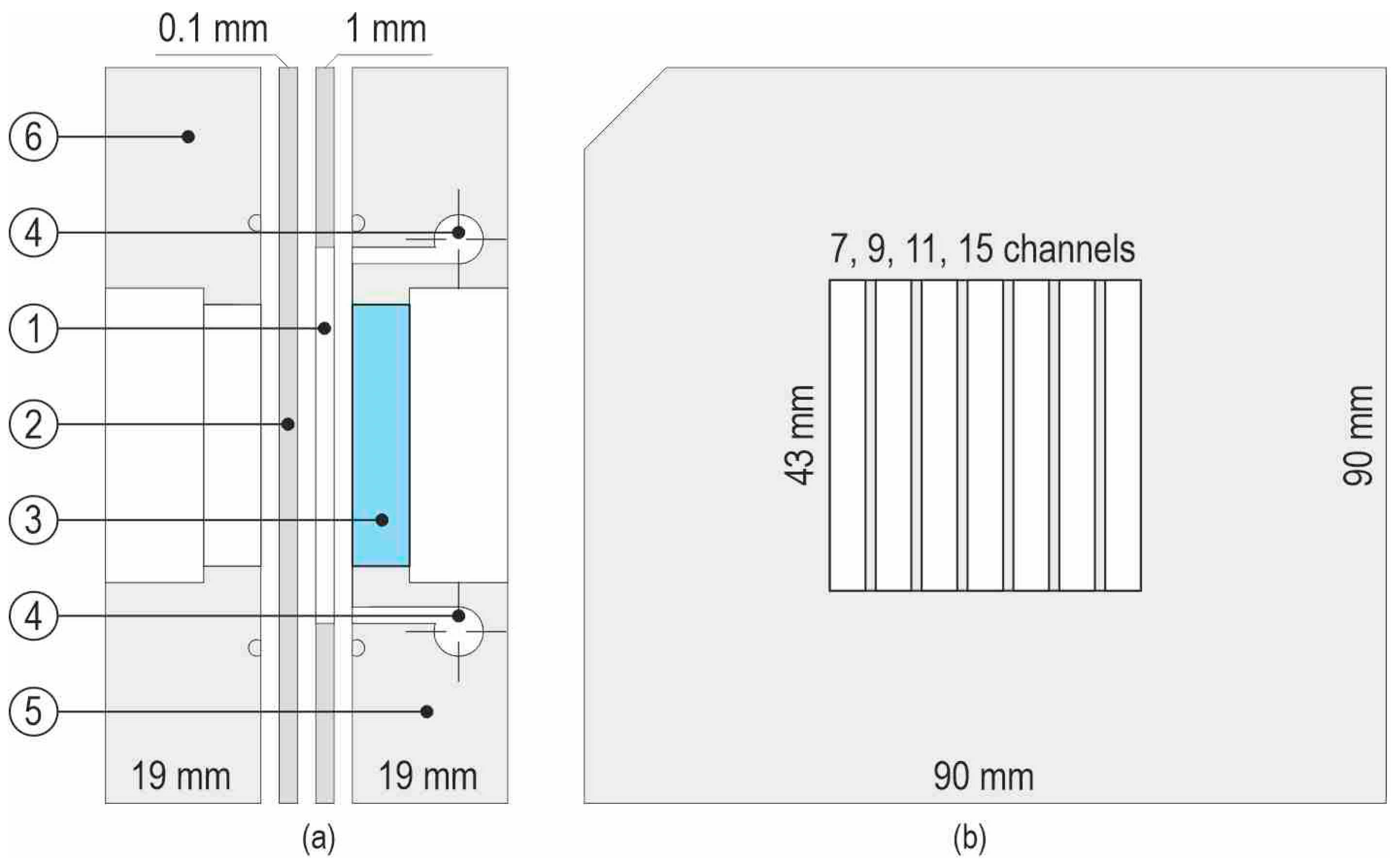
The schematic diagram of a compact heat exchanger as a test section with a group of parallel mini-channels is depicted in Figure 2. The main components of the test section in the longitudinal section showing separated parts are shown in Figure 2a, while a view of the front cover side of the test section with seven mini-channels is illustrated in Figure 2b. The side walls of the mini-channels are formed by a thin Teflon spacer (Figure 2a, 1). A thin plate made of Haynes-230 alloy (thickness about 0.1 mm) constitutes a heating wall (2). The Haynes-230 alloy plate is mainly made of Ni-Cr-W-Mo [27]. This alloy was selected for its values of electrical resistivity, assuming minor changes in resistivity with temperature. In addition to its excellent high-temperature strength and oxidation resistance, this alloy exhibits superior long-term stability and good fabricability. During the experimental series, the alloy plate was resistively heated (the Joule effect) by the heat source (an inverter welder, Spartus ARC ZX7-400B, Spartus, Miszewko, Poland). The current supplied to the heated plate was measured indirectly through a shunt (range from −60 to +60 mV) that cooperated with an acquisition module (Dataforth 8B32-01, Dataforth Corporation, Tucson, AZ, USA). Another acquisition module (Dataforth 8B40-01, Dataforth Corporation, Tucson, AZ, USA) was used to measure the voltage drop across the heated plate. Both modules were connected to the data acquisition station (Measurement Computing SC-1608G, Measurement Computing, Norton, MA, USA).
The heating plate comes into contact with the working fluid; the plate surface that contacts the flowing fluid is smooth or enhanced. A glass plate (3) is the opposite wall of the mini-channels. Due to its transparency, it is possible to observe the formation of the fluid pattern during flow. Other essential components of the test section include a channel body (5) and a front cover (6), both made of aluminium. Furthermore, in the inlet and outlet chambers (4), temperature and pressure sensors are placed. The length of mini-channels, corresponding to the temperature measurement on the heating plate, is 43 mm (thermograms on its outer side are recorded due to infrared thermography; the surface is coated with black paint of known emissivity). The depth of the mini-channels is 1 mm, while the width of each mini-channel depends on the total number of channels formed in the test section. The main geometric parameters of mini-channels are listed in Table 2.
The spatial position of the test section is manually adjusted before starting the experimental series. It is possible to change the spatial orientation of the test section with a 15-degree increment throughout the entire rotation range of the test section (i.e., 360 degrees), assuming that the horizontal position with the fluid flowing above the heating plate. However, for this publication, three orientations were considered: horizontal with fluid flowing above the heating plate (position ‘0’), and vertical with an upward flow (position ‘90’) and downward flow (position ‘270’).
In this study, five refrigerants manufactured by the 3M company (Fluorinert FC-72 and four other fluids named 3M™ Novec™, 3M Center, St. Paul, MN, USA) and distilled water were selected as working fluids. Table 3 shows the main properties of each fluid considered.
In a previous experimental work [29], various enhancing surfaces on the plate–fluid contact surface were tested in terms of finding solutions to achieve the intensification of heat transfer processes during flow boiling. The selected types of heating-plate wall surface in terms of roughness are characterised in Figure 3 and Table 4. In Figure 3, microscopic images and 3D topographies of a smooth surface (Figure 3a) and various groups of surface development (Figure 3b–f) are illustrated. Table 4 contains the characteristics of the surface roughnesses for the selected main groups of enhanced surfaces of the heating plate. In each case, apart from the smooth surface, there were different variants and attempts to achieve as high a level of surface development as possible. Due to the similar experimental results within each group, only those surface types that achieved significantly higher heat transfer coefficient values were reported.

2.2. Experimental Uncertainties

In Table 5, the uncertainties of the experimental parameters are listed, according to the manufacturer of the devices or standards.
It should be underlined that thermocouples (K-type, Czaki Thermo-Product) were additionally calibrated [30].

2.3. Research Methodology

During each experimental series, after the mass flow rate and pressure at the mini-chanel inlet are set, a gradual increase in the electric power supplied to the heating plate is provided. Investigations are usually carried out under stable stationary thermal and flow conditions. A detailed description of the experimental apparatus and methodology is provided in [26].

2.4. The Reference Experiment

Among the experimental series conducted on the test stands, a reference experiment was chosen based on specific basic geometric and material parameters, along with established thermal and flow conditions. The base characteristics of the reference experiment are shown in Table 6. During the reference experiment, the constant mass flow rate was established. There was a laminar flow in the mini-channels. The data collected for one value of the imposed flux were taken into consideration. The test section comprised seven mini-channels. The working fluid was Fluorinert FC-72 flowing laminarly in the mini-channels. In the part of the experiments that are of special interest, the heat transfer mechanism belongs to single-phase forced convection. The dimensions of a single mini-channel were as follows: 1 mm (depth), 4 mm (width), and 43 mm (length). The test section was vertical with an upward flow (position ‘90’). A 0.1 mm thick plate, made of Haynes-230 alloy [27], was a heating wall with a smooth surface that contacted the flowing fluid. The temperature of the outer surface of the plate (in contact with ambient air) was measured by infrared thermography (FLIR A655sc infrared camera). The plate on the outer side was coated with a black paint of known emissivity. Flow patterns were observed through the glass plate and recorded by a high-speed camera.
Based on the experimental data, heat transfer coefficient calculations were performed using T-functions, according to the adopted computational model that accounted for heat flow in the test section with mini-channels, considering two directions (2D mathematical model). Furthermore, numerical calculations were performed on the same data using the commercial CFD programme Siemens Simcenter STAR-CCM+. The validation of the results obtained from the numerical simulations, which compared the temperature distribution obtained from the numerical calculations with measurements from an infrared camera, was presented in [26]. Subsequent numerical simulations were conducted using Simcenter STAR-CCM+. The COQ parameters, identified by Quality Function Deployment (QFD) analysis, were sequentially implemented into the reference simulation. The simulation results highlighted COQ characteristics that could have the greatest impact on the efficiency of compact heat exchanger operation (reaching high values of the heat transfer coefficient). Thus, by applying QFD analysis, conducting analytical numerical calculations using T-functions, and performing a series of numerical simulations in the Simcenter STAR-CCM+ programme, we gained insights into which COQ parameters should be incorporated into the compact heat exchanger design and operating conditions to achieve its most efficient heat transfer.
In Section 3, a mathematical model and an analytical–numerical method with the use of T-functions are described. The results of calculations using Siemens Simcenter STAR-CCM+ version 2020.2.1 Build 15.04.010, are briefly mentioned in Section 4.

3. Mathematical Model, Heat Transfer Calculations, and Example Results

3.1. Main Aim

The aim of this chapter is: (i) to report assumptions for the mathematical model of heat transfer during fluid flow in a central mini-channel of a model compact heat exchanger, (ii) to describe the main boundary conditions and governing equations, and finally, (iii) to explain computation methods to obtain local heat transfer coefficients at the contact surface between the working fluid and the heating wall (plate) of the asymmetrically heated mini-channel. An analytical–numerical method with the use of T-functions, that is, the Trefftz method, was applied to the calculations. The example heat transfer results from the calculations for Fluorinert FC-72 are illustrated and analysed. The results of the calculations based on the reference experiment are compared with the results obtained from numerical simulations according to Simcenter STAR-CCM+.

3.2. Assumptions for Calculations

The experiment provides information on the density of the heat flux delivered to the heating plate, the temperature and pressure of the cooling fluid at the inlet and outlet to the test section mini-channels, the temperature field at the outer surface of the heating plate, atmospheric pressure, and ambient temperature. Additionally, the physical properties of the working fluid and the properties of the heating plate, the geometrical parameters of the test section, and as its spatial position are known. Hence, it is possible to estimate the heat transfer intensity, characterised by the values of the heat transfer coefficient at the heating plate–cooling fluid contact, which determines the efficiency of the compact heat exchanger configuration.

3.3. Analytical–Numerical Method with the Use of T-Functions

The proposed mathematical model is a modification of the model presented in [31]. It assumes that the heat exchange process in the test section occurs at a steady state, and that the physical parameters of the mini-channel elements, including the heating plate and cooling fluid, are independent of temperature. Additionally, it assumes that the heat exchange occurring on the sidewalls of the mini-channel does not affect the thermodynamic parameters of its central part. It is also assumed that the temperature changes in the heating plate and the fluid along the width of the mini-channel are negligible. This allows for limiting the considerations to the central part of the mini-channel only, with the heating plate additionally neglecting heat conduction along the length of the channel and assuming that the temperature of the heating plate, Th, satisfies the energy conservation equation in the form:
d 2 T h d y 2 = q V λ h   for   0 < y < δ h
For Equation (1), it is assumed that, at the boundary, y = 0, the heating plate temperature distribution, Th,pol (x), is known, that is:
T h x , 0 = T h , p o l   x
and that this edge is insulated because heat losses to the environment are negligible [30].
T h y = 0   for   y = 0
The analytical solution of Equation (1) with boundary conditions (2) and (3) takes the form of the following dependence:
T h x , y = T h , p o l   x q V 2 λ h y 2
When determining the fluid temperature distribution in the mini-channel, heat conduction along its length (x) is considered, and in the direction perpendicular to it, namely, the depth of the mini-channel (y). Additionally, for the cooling fluid, the following assumptions were made:
  • The fluid flow in the mini-channel is steady and laminar (Reynolds number < 2300) with a constant mass flow rate;
  • The temperature and pressure of the fluid at the inlet and outlet to/from the mini-channel are known from experimental measurements;
  • The velocity of the fluid has only one non-zero parabolic component, v(y), parallel to the heating plate;
  • the heating plate and the cooling fluid are in perfect thermal contact, meaning the temperature and heat flux are equal on the contact wall between the plate and the fluid;
  • For saturated boiling, the emerging vapor bubbles absorb part of the energy supplied to the fluid and are treated as a negative heat source, Ω x [30].
The fluid temperature, Tf, satisfies the energy equation in the form:
λ f 2 T f = v y c p ρ f T f x + C Ω x
where 2 = 2 x 2 + 2 y 2   is the Laplace operator and the negative heat source, Ω x , is calculated in the same way as in [30]. The constant C takes the value 0 when subcooled boiling occurs in the mini-channel, and value 1 when saturated boiling occurs in the mini-channel.
Determining the temperature of the fluid involves solving the problem of inverse heat conduction. Similar to [31,32], this problem was addressed using T-functions, resulting in the function Tf that exactly satisfies Equation (5) and approximately meets the adopted boundary conditions. Knowing the distribution of the heating plate temperature allows us to determine the local heat transfer coefficients based on the Robin condition:
α x = λ h T h y x , δ h T h x , δ h T f , a v e x = q T h x , δ h T f , a v e x
where q means heat flux density and the reference fluid temperature, Tf,ave (x), is computed by analogy to [31]. The proposed calculation method has its advantages but also its limitations. The method with T-functions can be employed to solve engineering problems described by linear differential equations in areas of simple shapes, but it does not require a high computing power and sophisticated software. The method returns a solution that exactly satisfies the governing equation while the boundary conditions are satisfied approximately. A wide range of applications of the Trefftz method for solving both direct and inverse engineering problems can be found in [31,32,33,34].
It should be emphasised that analogous calculations were performed for each experimental series described in Section 2. These results were used in Section 5 in the QFD analysis.

3.4. Heat Transfer Coefficient Uncertainty

The mean relative error of the heat transfer coefficient, ε , was calculated using the following formula:
ε = 1 L 0 L 1 α x α q Δ q 2 + α T h Δ T h 2 + α T f , a v e Δ T f , a v e 2 0.5 d x
where:
  • Δ q the accuracy of the calculated heat flux density was estimated in parallel to [28], considering errors of: current intensity (supplied to the heated plate), voltage drop (across the heated plate), and area of the heated plate;
  • Δ T h = Δ T + T h x Δ x —the accuracy of the heated plate temperature;
  • Δ T f , a v e = Δ T f + T f , a v e x Δ x —the accuracy of the fluid temperature;
  • with the following assumptions:
  • Δ T = 2   K —uncertainty of the heated plate temperature, measured by the FLIR A655SC infrared camera (FLIR Systems Inc., Wilsonville, OR, USA), while the accuracy of this camera is ±2 °C or ±2% in the temperature range of −20 ÷ 120 °C (see Table 5);
  • Δ T f = 0.34   K —uncertainty of fluid temperature data obtained with additionally calibrated K-type thermocouples, analogous to [30];
  • Δx = 0.0001 m—uncertainty of infrared thermography temperature measurement location, as in [35].
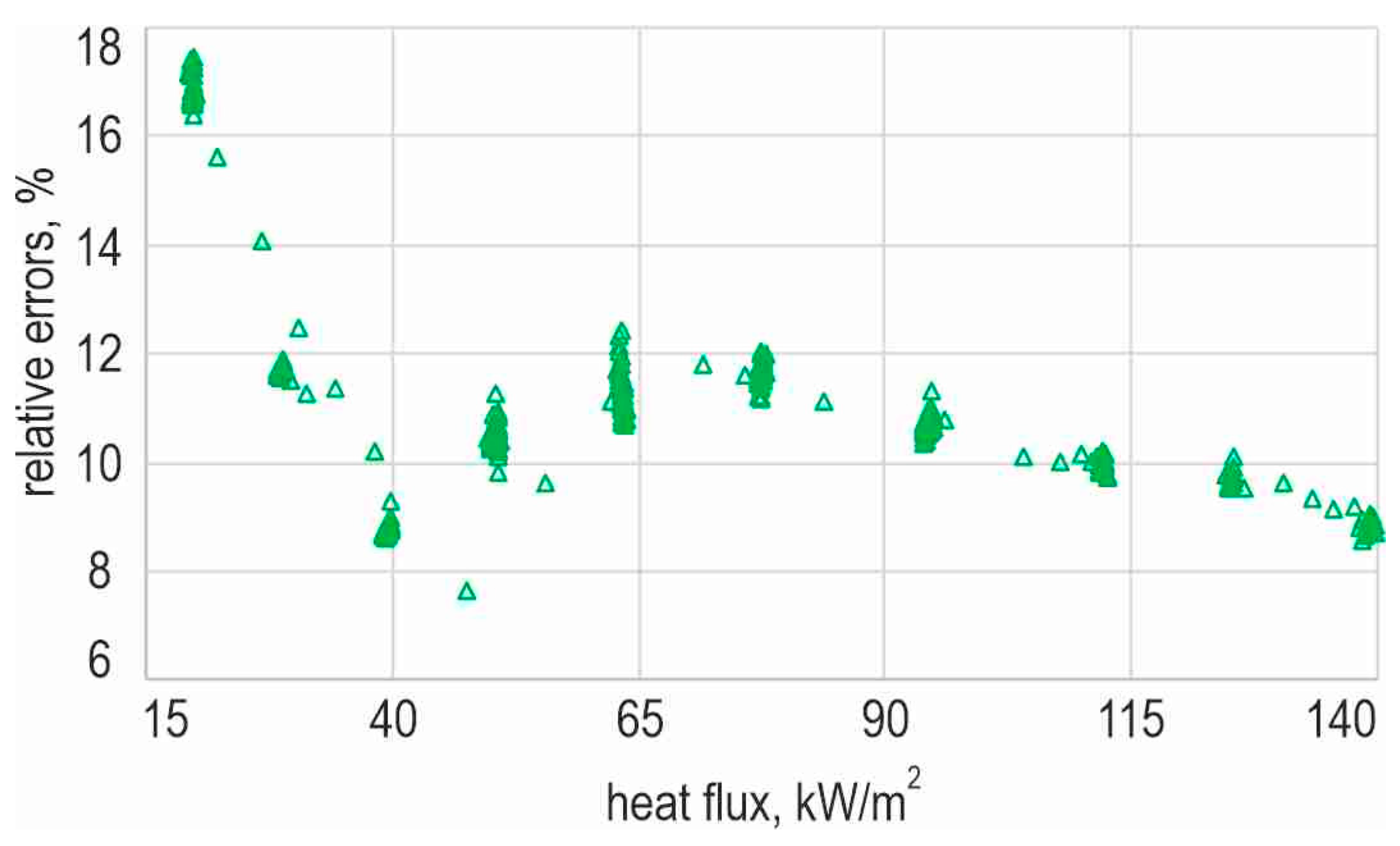
The relative errors of the heat transfer coefficients, ε, as a function of heat flux, are shown in Figure 4. These errors achieve their highest values for the lowest heat flux values, with a maximum not exceeding 17.46%. When analysing the dependence, it was observed that, as the heat flux supplied to the foil increases, the errors decrease, reaching a minimum value around 40 kW/m2. However, with higher values of heat flux, errors increase (up to a heat flux value of 60 kW/m2) and then decrease again, stabilising at an error value of 8%. Furthermore, the average relative error of the heat transfer coefficient is 11.33%.

3.5. Example Heat Transfer Results

3.5.1. Data from Experiments

The data presented concern the central mini-channel and the range of full data from the reference experiment, which is indicated in Table 7. The selected experimental data are reported in the following forms:
  • The heating plate temperature measurements obtained due to the IR camera as a function of distance from the mini-channel inlet—in Figure 5;
  • Boiling curves, plotted for selected distances from the mini-channel inlet—in Figure 6.
The heating plate temperature measurements obtained from infrared thermography are illustrated in Figure 5 as a function of distance from the mini-channel inlet. The temperature data were recorded for seven values of the imposed heat flux supplied to the heating plate, with regard to the reference experiment.
When analysing the data presented in Figure 5, it is noted that the temperature of the heating plate increases with an increasing heat flux. The temperature distribution along the distances of the mini-channels is rather uniform; with increasing the distance from the mini-channels inlet, a slight increase can be observed, and the highest values of temperature of the heating plate are achieved near the mini-channel outlet.
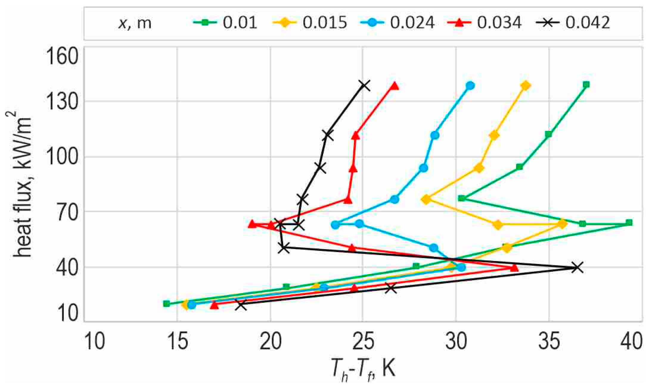
The boiling curves are shown in Figure 6 in the form of heat flux density as a function of the surface or the temperature difference between the heating plate temperature and the bulk working fluid temperature. The curves were plotted for five specific points in relation to the mini-channel inlet in the central axis of the mini-channel. To characterise the course of boiling curves, it is reported that: (i) when heat transfer occurs between the heated foil and the subcooled liquid due to forced single-phase convection, with increasing heat flux, the temperature difference increases; (ii) while the imposed heat flux increases, vapour nuclei are activated on the heater surface, leading to nucleate boiling; (iii) when spontaneous nucleation occurs, there is a sudden drop in heated surface temperature (this phenomenon is known as ‘nucleation hysteresis’; it appears as a decreasing function on the boiling curve); and (iv) a further increase in the heat flux results in the developed nucleate boiling, represented by an increasing function on the curve.
Analysing the boiling curves illustrated in Figure 6, it is noted that the temperature difference between the heating plate surface and the bulk fluid decreases with increasing distance from the mini-channel inlet. The highest value of the temperature drop during boiling initation is observed for the boiling curve constructed at a 0.042 m distance from the inlet. It should be emphasised that boiling curves provide insights into the complex heat transfer processes during flow boiling in mini-channels.

3.5.2. Heat Transfer Results According to Analytical–Numerical Method with the Use of T-Functions

The results of the calculations refer to the reference experiment. The heat transfer coefficients were obtained from calculations according to a 2D model, which were performed with the use of T-functions. The selected results are illustrated as follows:
  • Two-dimensional fluid temperature distribution—in Figure 7;
  • Heat transfer coefficient as a function of distance from the mini-channel inlet—in Figure 8;
  • Heat transfer coefficient as a function of heat flux—in Figure 9.
Firstly, the 2D heated-plate temperature distribution (x—direction along the flow; y—direction referring to the depth of the mini-channel) was determined from Equation (4), where the mesaurements’ temperature values were approximated using a polynomial. Then, the Trefftz method was used to calculate the fluid’s 2D temperature distribution in the mini-channel. Calculations of local heat transfer coefficients were the final step. The two-dimensional fluid temperature distributions obtained by the Trefftz method for three selected heat fluxes are shown in Figure 7.
When analysing the results shown in Figure 7, it can be observed that the fluid flowing in the mini-channel has a higher temperature at the wall in contact with the heating plate and at the outlet from the mini-channel. In particular, a significant temperature increase is noted in the boundary layer, as in the part of the flow adjacent to the heating plate surface that contacts the working fluid. For lower heat fluxes (Figure 7a), there is a homogeneous temperature on the mini-channel axis along the entire length of the channel. When the heat flux supplied to the fluid increases, the warmer fluid layers towards the centre of the channel, where the temperature increases. Generally, the fluid temperature in the mini-channel increases with the increase in the heat flux supplied to the heating plate. For larger heat fluxes, a temperature distribution similar to parabolic profile of the liquid velocity is recognisable.
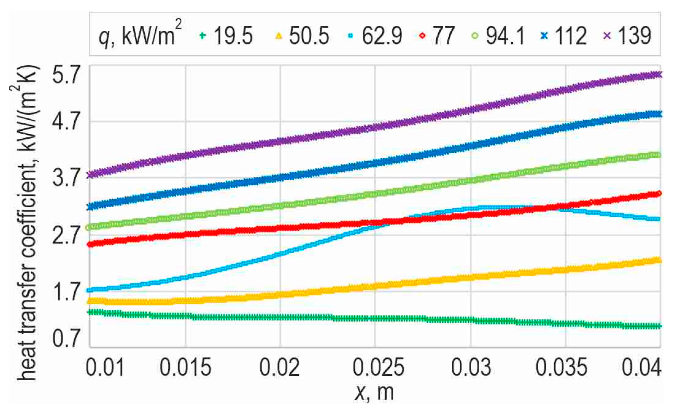
According to Figure 8, it can be observed that the values of the heat transfer coefficient range between 0.7 and 5.7 kW/(m2 K). Furthermore, the heat transfer coefficient increases with the distance from the channel inlet and reaches higher values for higher heat fluxes (except for the heat transfer coefficient for the lowest heat flux).
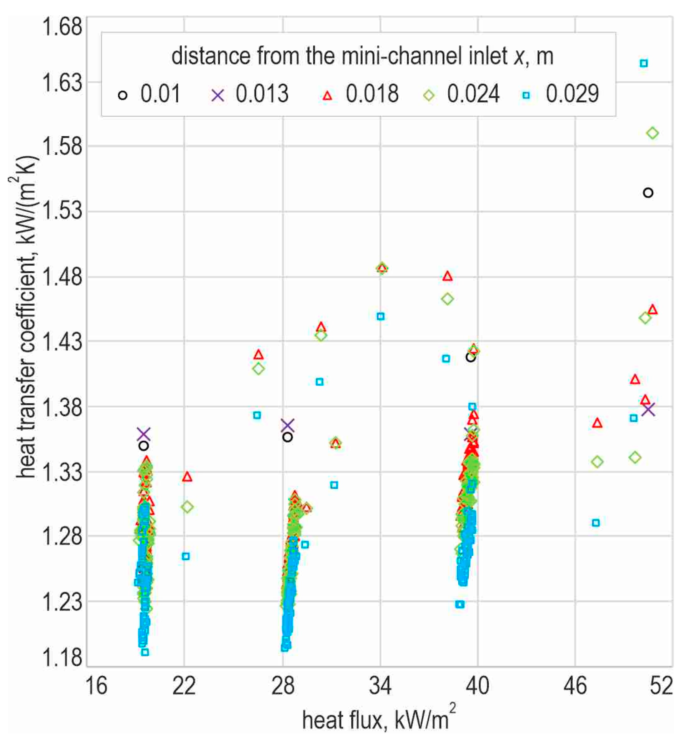
Figure 9 illustrates the relationship between the heat transfer coefficient and the imposed heat flux at various distances from the mini-channel inlet. This dependence was established based on the data obtained from the reference experiment. This dependence confirms the aforementioned observations: as the heat flux and the distance from the channel inlet increase, the values of heat transfer coefficients also increase.

4. CFD Simulations in the Simcenter STAR-CCM+ Programme

Based on the data from the reference experiment, numerical calculations were performed using the Simcenter STAR-CCM+ programme, version 2020.2.1 Build 15.04.010. Then, various numerical simulations were carried out and are discussed in the next chapters. In the numerical simulations, one parameter describing geometry, material, or work condition of the compact heat exchanger was modified (such as the number of mini-channels in a group, working fluid, thermal or flow parameters, and material parameters) while keeping the other parameters identical to those in the reference experiment. This allowed for a direct comparison of heat transfer efficiency among the different options considered for the compact heat exchanger with mini-channels. However, as the primary focus of this publication is on the application of the QFD method for analysing and forecasting the effective performance of a compact heat exchanger with mini-channels, numerical simulations performed using Simcenter STAR-CCM+ are not described in this work. Detailed information on the execution of numerical simulations and the validation of CFD results, compared to experimental data, has been thoroughly documented and analysed in a previous article, specifically in reference [26].
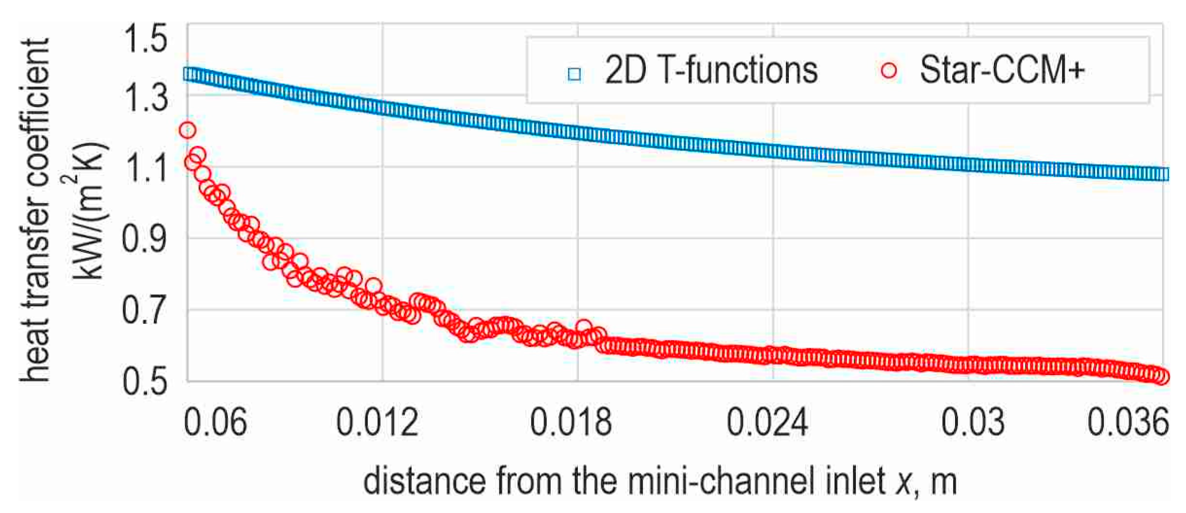
Figure 10 shows the results of the calculations determined with the aid of two different methods: analytical–numerical (mathematical 2D model with the use of T-functions) and numerical (according to the commercial CFD programme Simcenter STAR-CCM+). The results are presented in the form of heat transfer coefficient dependence as a function of distance from the mini-channel inlet (both calculations were based on identical data from the reference experiment). Such comparisons were conducted for the validation of the results obtained from the numerical simulation.
When analysing the relationships presented in Figure 10, it can be observed that the distribution of the heat transfer coefficient has a similar character for both calculation methods. The heat transfer coefficients obtained with the use of T-functions achieve higher values. Furthermore, the results are smoothed because of polynomial averaging, which is characteristic for computation with the aid of the Trefftz method. However, the numerical simulation results using the Simcenter STAR-CCM+ programme yield lower values of the heat transfer coefficients, and the influence of fluctuations observed in the temperature measurements is visible near the channel inlet. This characteristic feature is typical of numerical software and is also influenced by the computational mesh imposed on the channel and heated plate areas. Additionally, in the 2D approach, a simplified model of heat transfer between the heating plate and fluid was used, while in the Simcenter STAR-CCM+ programme, a 3D model of the test section of (a compact heat exchanger with mini-channels) was assumed. According to the authors, the convergence of the results is sufficient to compare the specific features of the compact heat exchanger. However, further work is planned to improve the numerical model of the heat exchanger, allowing greater consistency with real temperatures.
It should be underlined that, in the methodology of numerical simulations conducted in the Simcenter STAR-CCM+ programme, successive geometric and material parameters of the compact heat exchanger, as well as its operating conditions, were explored. A model of the compact heat exchanger with mini-channels was used from the reference experiment, in which only one parameter was varied, followed by a numerical simulation. Subsequently, the heat transfer coefficient was compared with that calculated in the reference simulation. This method explained the successive parameters of the compact heat exchanger and its operating conditions, allowing the determination of the heat exchange efficiency based on the resultant values of the heat transfer coefficient.

5. QFD Method

5.1. Characteristics of the QFD Method

In the Quality Function Deployment (QFD) method, as a structured methodology, quality is measured by customer satisfaction with a product or service. The methodology uses the House of Quality (HOQ) matrix as a starting point. This matrix focusses on identifying and prioritising the most crucial product or service based on customer requirements [36,37]. In the context of the research described, QFD was used to design a compact heat exchanger that meets the expectations and requirements.
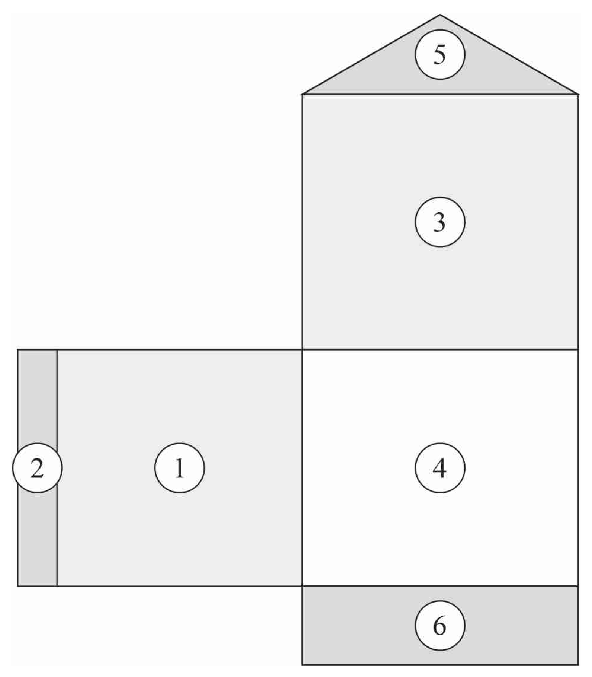
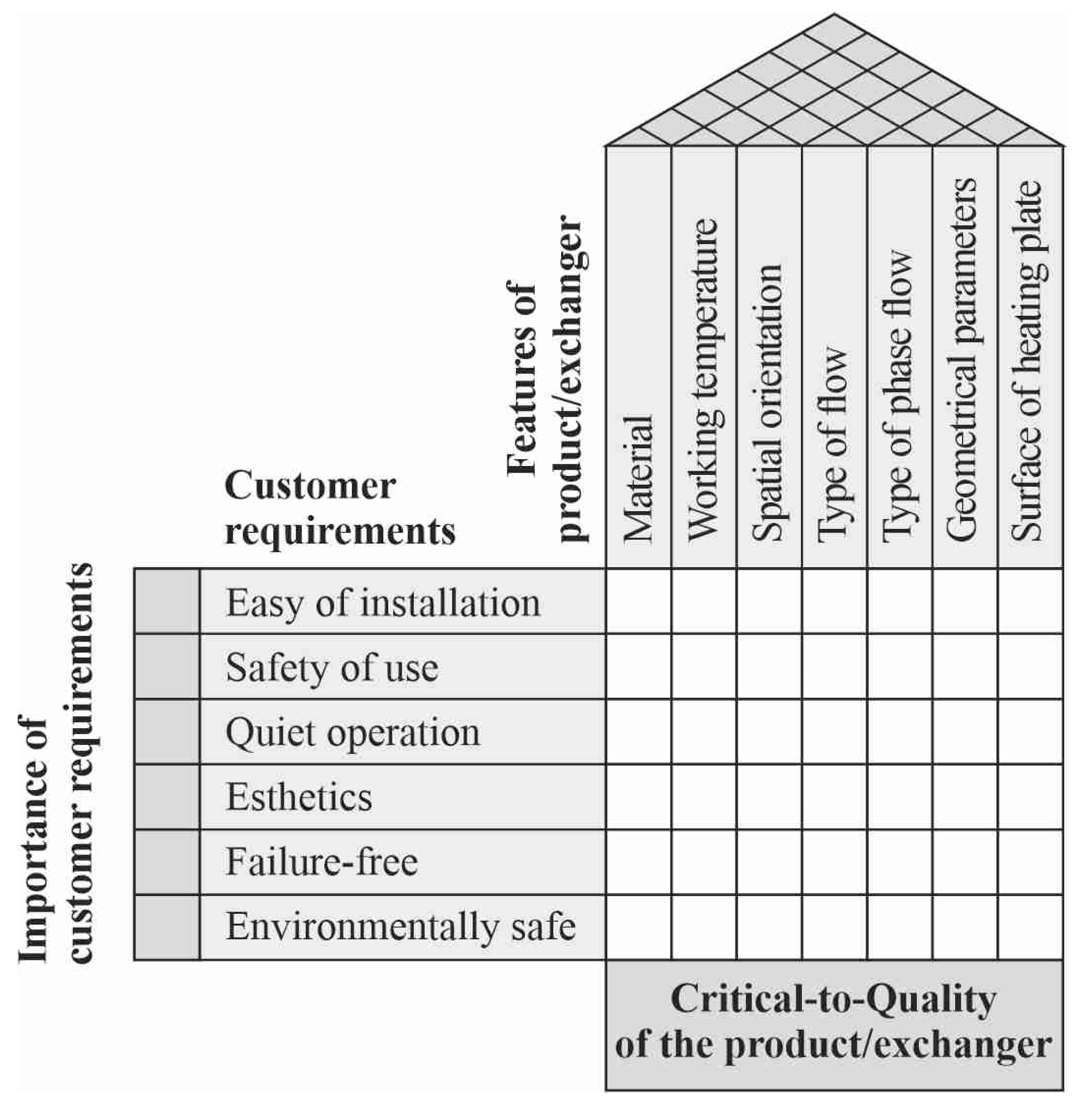
The QFD matrix proposed in this study uses the simplified process to detect the Critical-To-Quality (CTQ) characteristics of a compact heat exchanger, as shown in Figure 11. It could be added that Critical-to-Quality is a key element of the QFD method, allowing a precise determination of the aspects of the product or service that are most important for customer satisfaction. CTQ characteristics help in determining which features of the product/service have the greatest impact on quality and meeting user expectations.
The QFD methodology began by identifying the customer’s requirements (1), Figure 11 and the degree of their importance (2), usually based on questionnaires and surveys.
The next step in the QFD methodology is to identify the technical features (3) and relate them to customer requirements (4). Because the technical features of the compact heat exchanger are strictly defined by the specific intended use, the priority of these parameters is the highest at the design stage. The HOQ fields (3) were assumed on the basis of the experimental results collected in the experimental research [26,29,30,35].
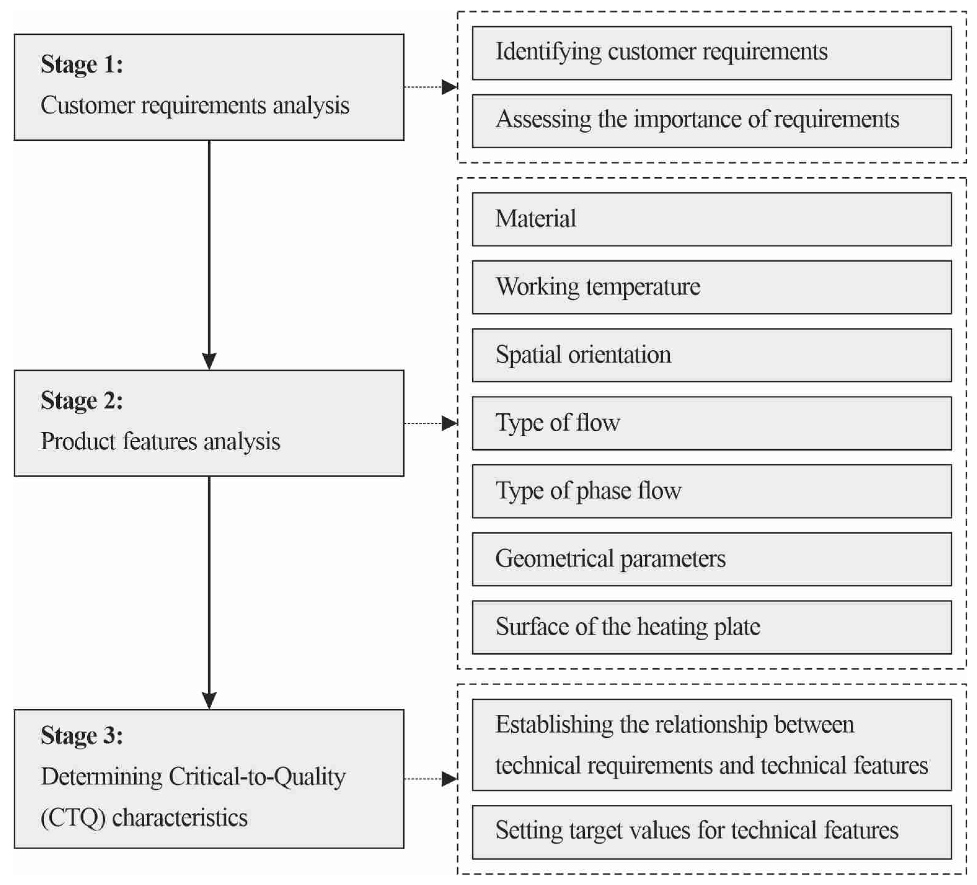
The HOQ roof indicates the functional correlation matrix between the individual technical features (5) of the compact heat exchanger. Then, the target values of the technical features are set, which leads to obtaining a construction with the highest efficiency. As a final step, the importance of technical features (6) is calculated using the importance of customer requirements and the relationship matrix. By controlling these key engineering characteristics, customer requirements are ultimately met. Figure 12 shows a flowchart explaining the successive steps in building the House of Quality (HOQ) for a compact heat exchanger with mini-channels.
In another part of this chapter, the subsequent steps of analysis and the obtained Critical-to-Quality (CTQ) factors that may have the most significant impacts on improving the thermal efficiency of a compact heat exchanger with mini-channels are discussed.

5.2. Main HOQ Matrix

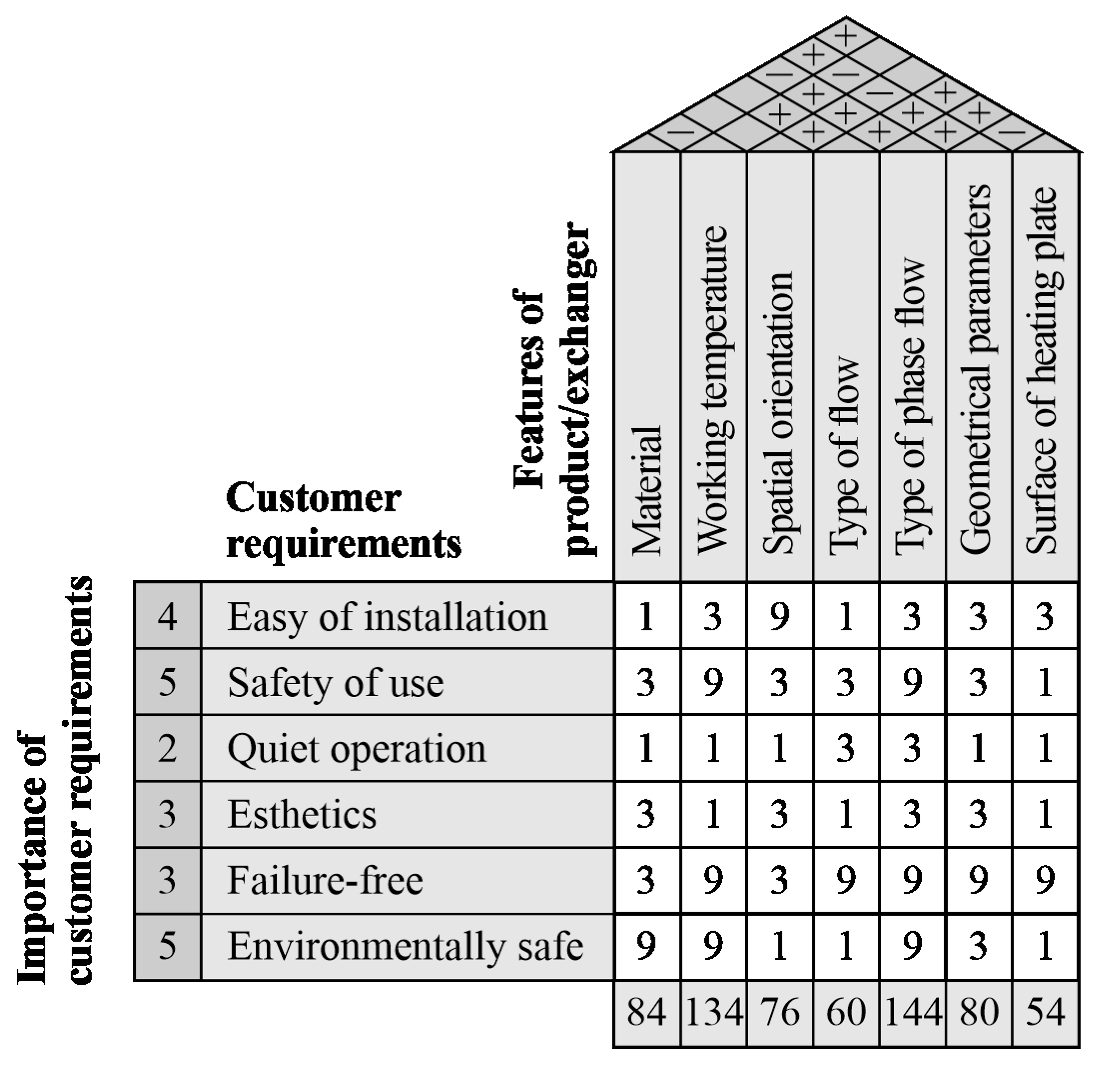
The initial step in the development of the HOQ matrix (Figure 13) was to define the needs of the customers, which were obtained through a questionnaire with answers to choose from. From the collected responses, the most frequently recurring features were selected and compared with the characteristics of compact heat exchangers that emerged from the results of long-term research, i.e., material, working temperature, spatial orientation, flow rate of the working fluid (type of fluid flow), operation without or with phase changes in the liquid (type of phase flow), geometrical parameters, and roughness of the heating plate surface. A scale in the range of 1–5 and ratings from lowest importance (1) to most important (5) were used to weight customer requirements. Safety of use and environmental friendliness (rating 5) were considered the most important. Less important to customers were ease of installation (rating 4), aesthetics (rating 3), trouble-free operation (rating 3), and quiet operation (rating 2).

5.3. Feature of a Compact Heat Exchanger: Material

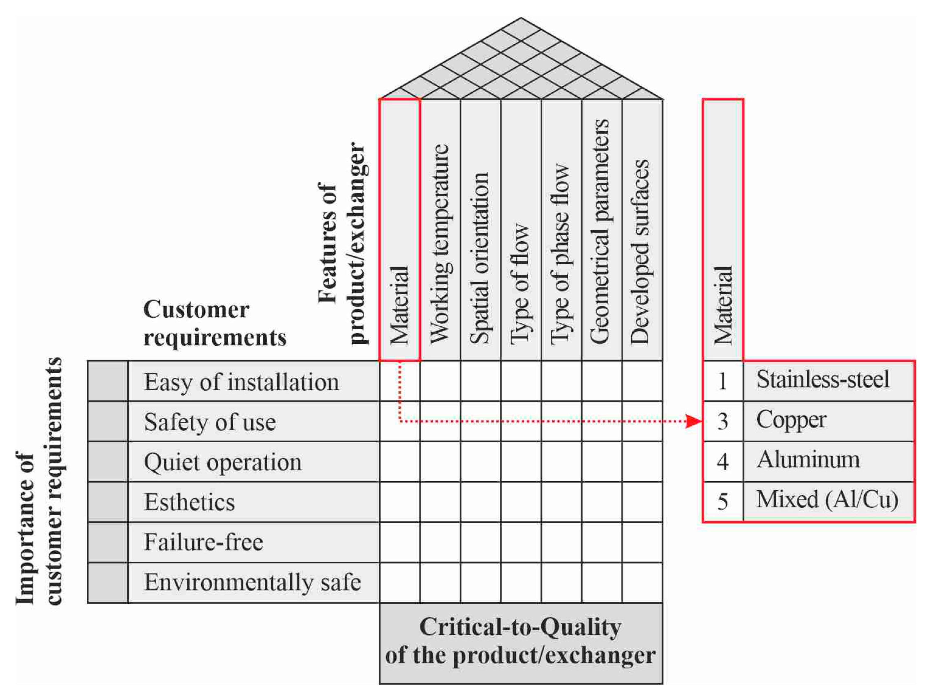
The choice of material for the target heat exchanger is very important. Various construction materials, such as stainless steel, copper, aluminium, and their alloys (or a combination thereof), are crucial during the conceptual and construction stages of the development of a compact heat exchanger. These materials play an important role in achieving the best possible efficiency of the heat exchanger while ensuring ease of manufacturing. The selected materials are summarised in Figure 14, followed by an assessment of their suitability to determine the most favourable choice for the construction material dedicated to the compact heat exchanger.
Two materials were selected for further analysis: aluminium AW-2017A (AlCu4MgSiA) and mixed (main construction elements made of aluminium and a heating plate made of copper), ensuring better heat transfer from the electronic components to the working fluid flowing in the mini-channels of the compact heat exchanger. Stainless steel was eliminated from further consideration due to its thermal properties and more difficult processing during manufacture. Copper, which had the best thermal performance among the collected materials, was also not selected for economic reasons.

5.4. Feature of a Compact Heat Exchanger: Working Temperature

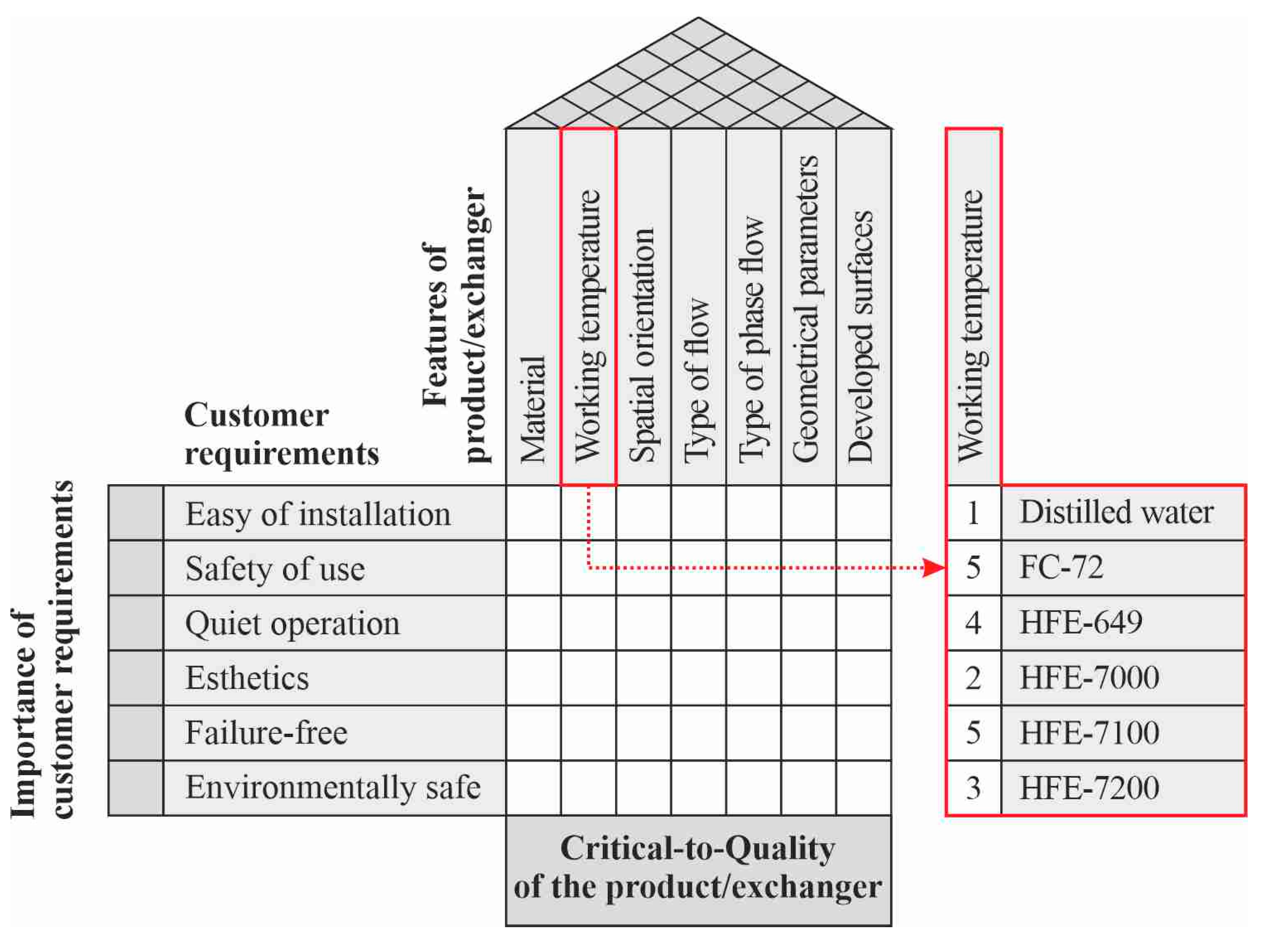
The second feature of the product, which is a compact heat exchanger, is related to the working temperature (as shown in Figure 15). This temperature is highly dependent on the properties of the working fluid, particularly its boiling point. During computer operation, electronic components, such as the CPU or GPU, can heat up significantly, exceeding 100 °C. If the cooling system does not function properly, this elevated temperature poses a risk of damage or system destruction. Therefore, precise temperature control is crucial to maintain the efficiency and reliability of the devices.
It is possible to control the operating temperature range by selecting a working fluid flowing in mini-channels of the compact heat exchanger. During the experiments, several working fluids were used, which differ in their physical properties and boiling points. The main properties of these fluids are listed in Table 3. Distilled water, although ecologically safe, was discarded from possible choices as a working fluid because of its rather high boiling temperature. The other working fluids (low-boiling refrigerants) guarantee the lower working temperature of the heat exchanger, which has a beneficial effect on operating conditions. For processors, a temperature of 100 °C and higher causes immediate overheating, which can lead to the destruction of the device. According to this demand, low-boiling refrigerants should be used as cooling fluids for electronic systems. Therefore, for further consideration, two low-boiling refrigerants were selected to guarantee a favourable thermal operating range for a compact heat exchanger. These were FC-72 and HFE 7100, manufactured by 3M. In addition to the preferred operating parameters, these fluids also ensure safety of use in a closed-circuit system.

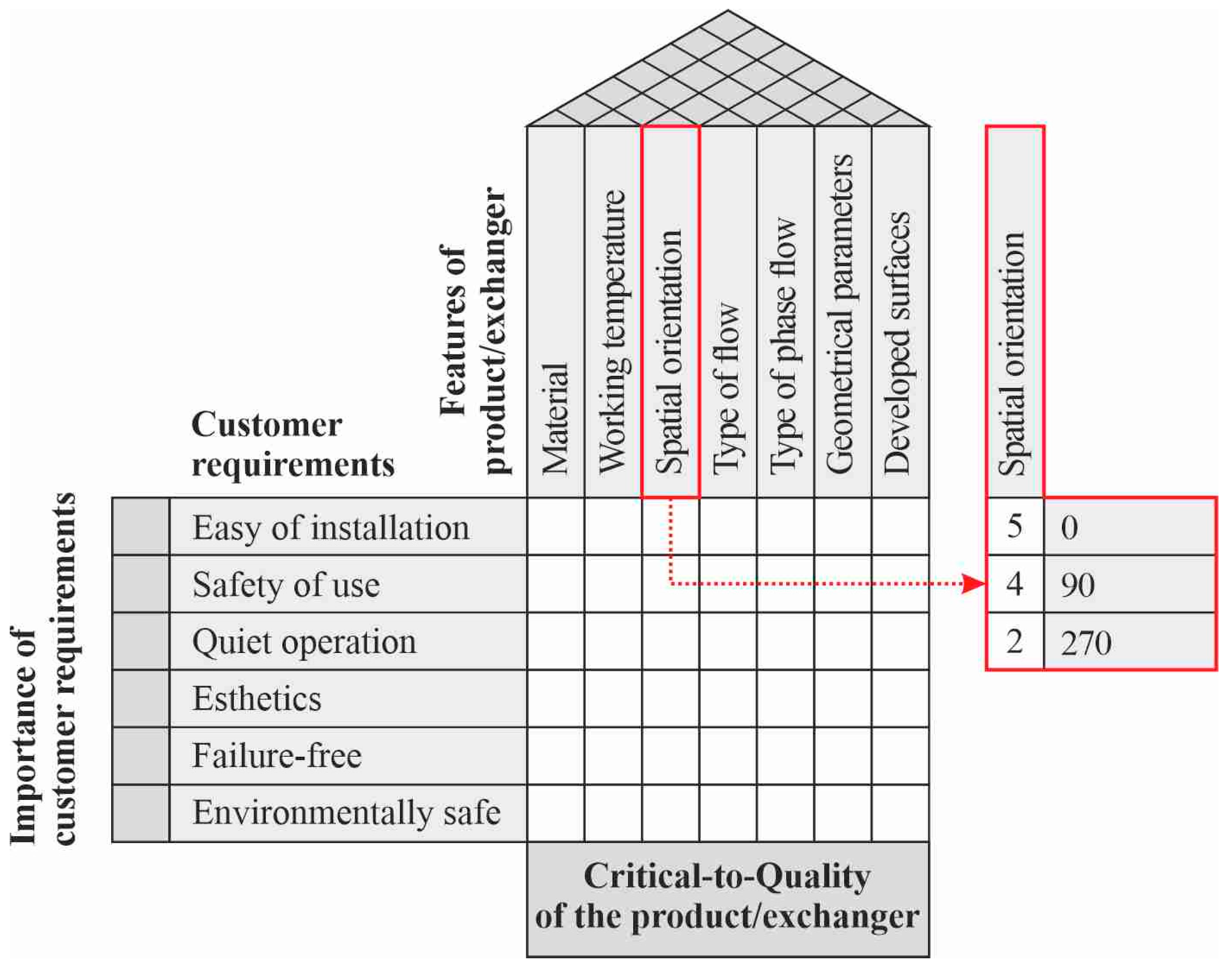
5.5. Feature of a Compact Heat Exchanger: Spatial Orientation

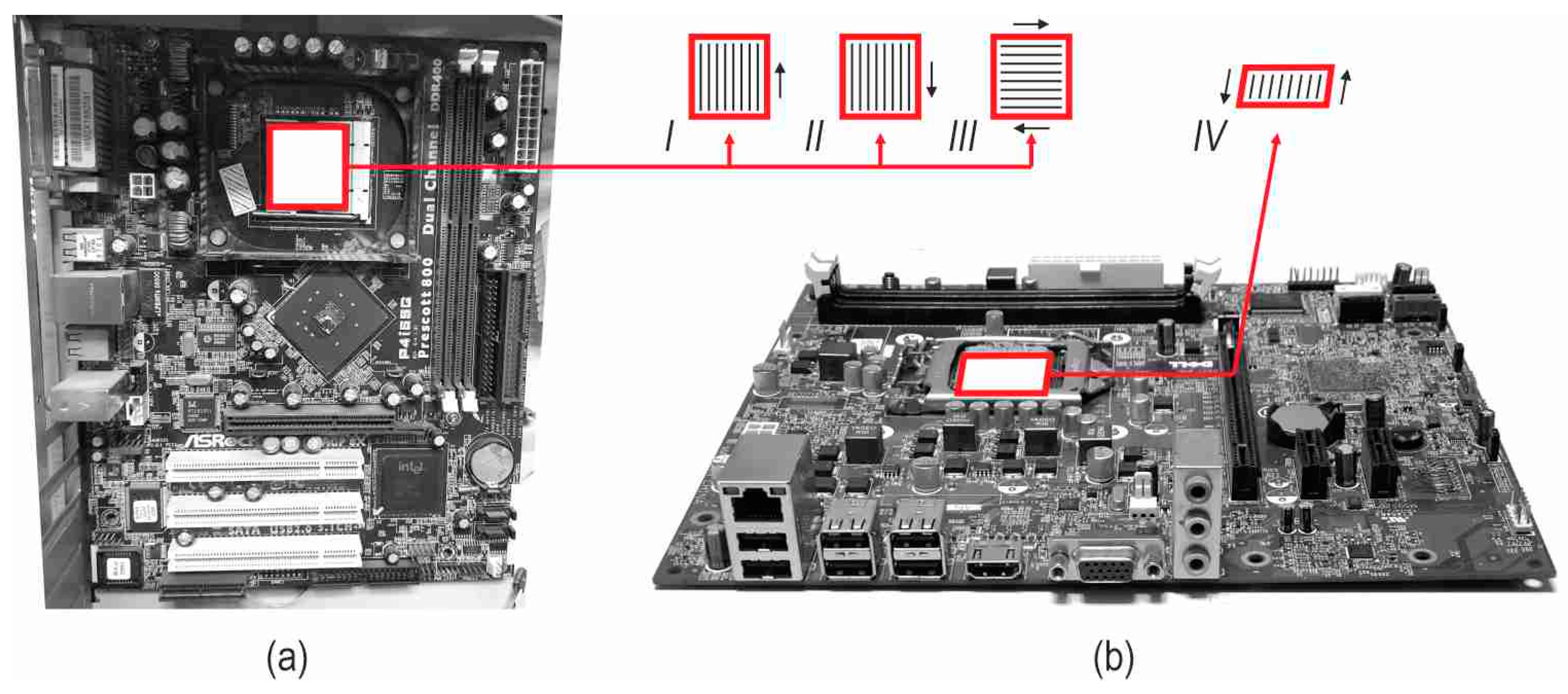
Another feature of a compact heat exchanger is its spatial orientation. The most common position of a computer motherboard is either vertical or horizontal. Typical positions of a compact heat exchanger are shown in Figure 16.
As can be seen, when the electronics are in a horizontal position, the orientation of a compact heat exchanger becomes irrelevant (as shown in Figure 16b). However, the situation changes significantly when the processor is mounted on a vertically positioned motherboard (as depicted in Figure 16a). In this case, there are up to three possible heat exchanger orientations: upward flow in the mini-channels (Figure 16a(I)), downward flow (Figure 16a(II)), and lateral flow from one side to the other (Figure 16a(III)).
Two spatial orientations of the mini-channels from the three analysed were chosen for further analysis (Figure 17):
  • Position ‘0’ when the heating plate (or the processor surface) is below the channels through which the fluid flows (corresponding to position IV; Figure 16b);
  • Position ‘90’ when the fluid flows upward (corresponding to position I; Figure 16a).

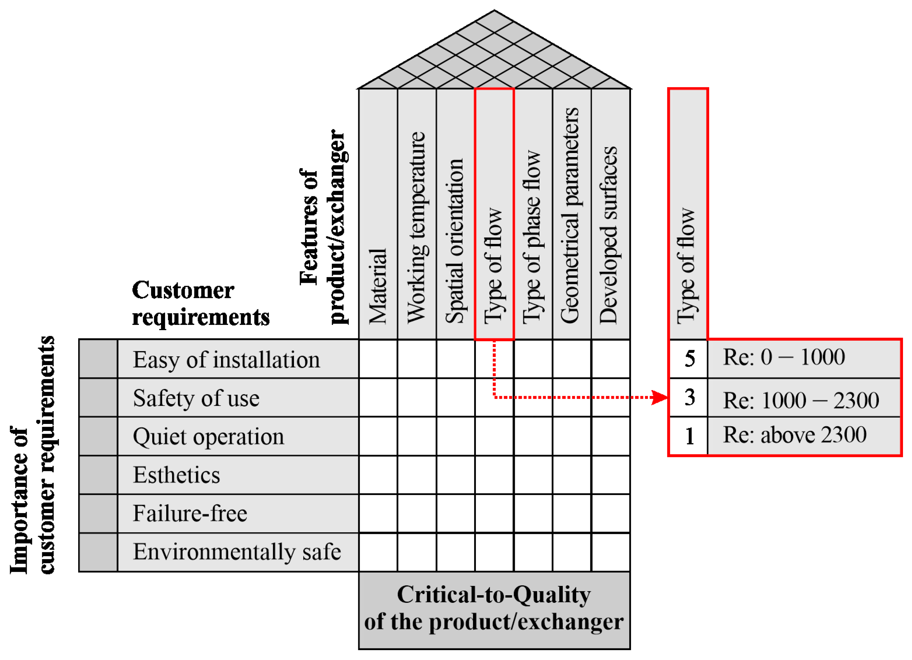
5.6. Feature of a Compact Heat Exchanger: Type of Flow

The next feature important for the thermal efficiency of a compact heat exchanger is the type of working fluid flow in the mini-channels, which depends on the value of the Reynolds number (Re). In Figure 18, the considered types of flow are reported, depending on the Reynolds number values.
For further analysis, laminar flow with a Reynolds number up to 1000 was assumed. According to the fluid mechanics theory, a Reynolds number with a value below 2300 indicates laminar flow.

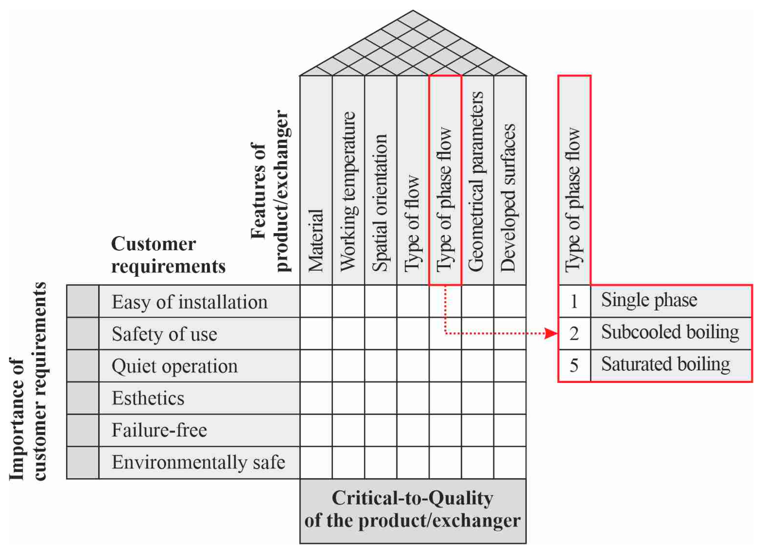
5.7. Feature of a Compact Heat Exchanger: Type of Phase Flow

The next feature analysed for the operation of a compact heat exchanger was the flow of the working fluid with or without a change in phase. Figure 19 summarises the types of heat exchanger operations due to a single-phase flow (‘single phase’) or two-phase flow (depending on the boiling regime: ‘subcooled boiling’ or ‘saturated boiling’).
To identify the boiling areas, it was assumed:
  • If superheating of the heating surface (the difference in temperature of the heated surface and the saturation temperature of the fluid) does not occur (the value of the difference is less than 0), subcooled boiling occurs;
  • When surface superheat is positive, saturated boiling takes place.
A compact heat exchanger with a flow of the working fluid without a phase change is the safest option for the device. However, this choice comes with the drawback of a lower thermal efficiency compared to the two-phase flow.
During the initial stage of the two-phase flow, a subcooled boiling mechanism occurs. This is characterised by the formation of the first vapour bubbles near the heated wall in the boundary layer. The fluid temperature in the core of the flow is significantly lower than that of the heating wall. Subcooled boiling, which involves a two-phase flow with a small vapour-phase contribution, is more advantageous than a single-phase flow. Typically, an increase in the heat transfer coefficient is observed in the subcooled boiling region.
During saturated boiling, the highest values of the heat transfer coefficient occur in comparison to single-phase flow and subcooled boiling, and thus a heat exchanger with a two-phase fluid helps to achieve higher thermal efficiency. Therefore, with a further development of boiling, a first boiling crisis can occur, in which there is a sudden increase in the temperature of the heat exchanger wall after the fluid completely evaporates. This process can lead to failure, unsealing, or even the complete destruction of the device. When choosing the feature ‘saturated boiling’, it is necessary to analyse the construction of a compact heat exchanger, for example, using the FMEA method, and appropriately design the key components of the device. However, the benefits exceed the risks and are quantifiable in the form of highly efficient flow and intensive heat transfer (higher values of the heat transfer coefficient). To prevent the occurrence of the first boiling crisis, the precise control of operating temperatures in compact heat exchangers is crucial.
It is also worth noting that the change in boiling mechanisms from a single-phase forced convection to the subcooled boiling region may be accompanied by the presence of a so-called ‘zero boiling crisis’ (or ‘nucleation hysteresis’). A sudden drop in the wall temperature is not usually dangerous to the operation of a compact heat exchanger, but the phenomenon usually disturbs its operation. Fluctuations in the fluid flow and increases and fluctuations in pressure are generally associated with the presence of instabilities in temperature, pressure, and fluid flow. Sometimes, the presence of vapour bubbles during cooling is undesirable, especially in applications such as the cooling of nuclear reactors.
Given the above considerations, the operation of a compact heat exchanger with the saturated boiling of the working fluid was assumed for further analysis. However, this has some limitations in terms of operational safety: the compact heat exchanger must be scientifically designed to work with this type of phase flow.

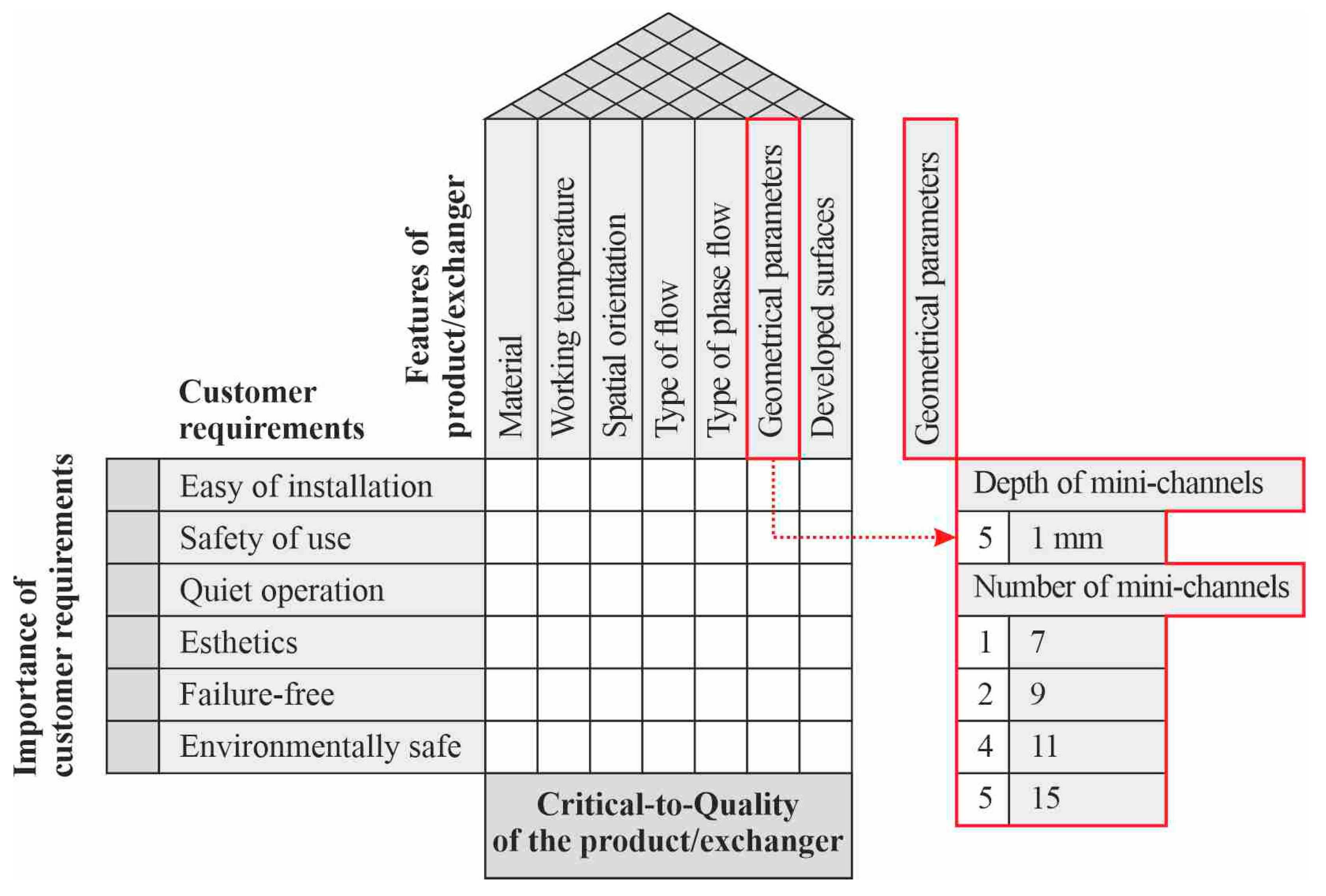
5.8. Feature of a Compact Heat Exchanger: Geometrical Parameters

The subsequent technical feature of a compact heat exchanger considered is its geometrical parameters. The crucial geometrical parameters are associated with the number of mini-channels and the smallest dimension of each mini-channel, as depicted in Figure 20.
The mini-channel depth is a geometrical parameter that was considered in the range of 0.5 to 2 mm, according to the experimental research. The higher efficiency of exchangers with mini-channels of a hydraulic diameter less than 3 mm, compared to conventional channels, is well-documented in the literature. Spacers of various thicknesses were used for the construction of the test section (see Figure 2), made of Teflon (PTFE), with several thicknesses: 0.5 mm, 0.7 mm, 1 mm, 1.5 mm, 1.7 mm, and 2 mm. A series of laboratory tests were carried out for each of these channel geometries. Based on the analyses from the experimental work, a mini-channel depth of 1 mm was chosen. Test modules with channel depths greater than 1 mm achieved lower heat transfer coefficient values in comparison. On the other hand, the flow in mini-channels with a depth lower than 1 mm was accompanied by significant flow resistance and the backflow of the working fluid, leading to large flow instabilities.
Compact heat exchangers that use sets of channels ranging from a dozen to several dozens have been analysed during in situ research work. The results, which were collected, indicate that a more homogeneous fluid distribution in the channels is achieved for up to 15 mini-channels in a group. Furthermore, increasing the numbers of mini-channels in the test section of the proposed geometry are more likely to cause undesirable processes as: large operating instabilities associated with an irregular flow, backflow phenomena in the mini-channels, or the sudden complete evaporation of the working fluid. The test sections with 7, 9, 11, and 15 mini-channels have been used in numerical simulations. The results indicate a more homogeneous fluid distribution in the mini-channels, the favourable performance of the heat exchanger, and its high thermal efficiency.

5.9. Feature of a Compact Heat Exchanger: Surface of the Heating Plate

The last feature of a compact heat exchanger is the roughness of the heating wall surface that is in contact with the working fluid flowing in the mini-channels. During the experimental investigations, the effect of the roughness of the heated wall on the value of the achieved heat transfer coefficient was studied due to the use of developed heating surfaces, from smooth to greatly enhanced, as porous. The surface roughness characteristics of the selected enhanced surfaces of the mini-channel heating wall used in the experimental investigations are presented in Table 4. The feature named ‘developed surfaces’ and the selected types of heating wall surface used for QFD analysis are specified in Figure 21.
A smooth surface was assumed as the reference surface for comparison with other surface types. Previous research has shown that some of the surfaces significantly improve heat transfer processes. These enhanced surfaces exhibit a larger heat transfer area compared to smooth surfaces. In addition, most of these enhanced surfaces feature artificial recesses that serve as nucleation centers for the formation of vapor bubbles. However, the least favorable surfaces, even worse than smooth, were heating plates with fiber-like (named ‘fibrous’) and powder-like (named ‘powder’) textures. Both of these surfaces had high spatial structures with open pores, leading to significant flow disturbances. Consequently, there was a noticeable decrease in the thermal efficiency of compact heat exchangers. On the other hand, electro-erosion textured, laser-textured, and laser-vibrating textured surfaces achieved good results in terms of thermal efficiency. However, electro-erosion textured surfaces suffered from low coverage across the entire heating plate surface. This uneven generation of surface features is a result of uncontrolled discharges and the formation of electric arcs, leading to the creation of craters, super-melts, and other unique surface developments. In addition to the relatively high level of surface development, laser-vibrating textured surfaces were not qualified for further studies, mainly because of the technical difficulties in producing suitable structures in the very limited space of the heat exchanger channels for cooling electronic components.
A smooth surface was selected for further analysis—mainly due to its ease of application for use in channels of small dimensions—and a laser-textured surface due to achieving effective heat transfer results, with a relatively high accuracy for obtaining a suitably developed surface.

5.10. The Results of the QFD Analysis

The features of a compact heat exchanger that received the highest ratings in terms of increasing the efficiency of the product were considered the most important, and thus a final selection was made. These properties were placed in the HOQ matrix shown in Figure 22.
After the completion of the HOQ (see Figure 22), a set of critical product characteristics was obtained from the analysis of the results. These are the working temperature and the type of phase flow. Furthermore, for the working temperature as a result of the analysis and comparative simulation, HFE-7100 fluid was selected. When considering the type of phase flow, saturation boiling was indicated as the most advantageous choice.
Finally, the following specific guidelines for the design of a compact heat exchanger dedicated to cooling miniature electronic elements were indicated:
  • Material: ‘mixed’, i.e., the main construction elements of a compact heat exchanger made of aluminium and a heating plate made of copper;
  • Working temperature: HFE-7100 fluid;
  • Spatial orientation: horizontal position—‘0’ position;
  • Type of flow: Reynolds number: 0–1000;
  • Type of phase flow: saturated boiling;
  • Geometrical parameters: 15 mini-channels (1 mm depth);
  • Surface of heating plate: laser-textured.
The proposed changes in the structure and operation of the heat exchanger resulted in a significantly improved heat exchange efficiency compared to that in the case treated as a reference experiment. Numerical simulations performed in the Simcenter STAR-CCM+ programme showed increases in the value of the heat transfer coefficient of up to 180% [38].

6. Conclusions

The article focused on designing a compact heat exchanger specifically for the cooling of electronic systems. The main aim was to analyse the fundamental features of the compact heat exchanger. The Quality Function Deployment (QFD) method and the proposed House of Quality (HOQ) matrix helped: (i) identify critical product features to enhance device performance; (ii) assess what product features influence the intensity of heat transfer during fluid flow through mini-channels, which allowed the design of a compact heat exchanger; (iii) reduce the development time for suitable design and material solutions; and for the end result, (iv) improve the thermal efficiency of the compact heat exchanger.
A mathematical heat transfer model was used to determine, based on the experimental data, local heat transfer coefficients and to validate the CFD modelling liquid flow and heat transfer in mini-channels. The combination of experimental testing and numerical simulations provided valuable information to achieve a better performance of the compact heat exchanger and prevented several years of tedious experimental research in the laboratory. The numerical simulations performed with the aid of CFD showed increases in the heat transfer coefficient of up to 180% compared to the case treated as reference.
Applying the QFD analysis to the collected results identified the following most important Critical-to-Quality features of the product, i.e., a compact heat exchanger dedicated to cooling miniature electronic elements: (i) the main structural elements: aluminium and copper, 15 mini-channels (1 mm deep) horizontally positioned, the heating plate developed by laser texturing, and (ii) the working fluid: HFE-7100, laminar flow, flow boiling (saturated). Furthermore, the most important customer requirements were safety of use and environmental friendliness of the product.
Future research is planned based on other quality management methods, such as FMEA (Failure Mode and Effects Analysis) and value analysis. Combining these methods with numerical analyses using CFD software may provide solutions that increase the safety of compact heat exchanger operation and reduce costs.

Author Contributions

Conceptualisation, A.P.; Data curation, S.H.; Formal analysis, A.P., S.H. and A.M.-J.; Funding acquisition, M.P.; Investigation, A.P.; Methodology, A.P., S.H. and A.M.-J.; Project administration, M.P.; Software, S.H., A.P.; Supervision, M.P.; Validation, M.P., A.P., S.H. and A.M.-J.; Visualisation, A.P.; Writing—original draft, M.P., A.P., S.H. and A.M.-J.; Writing—review and editing, M.P., A.P., S.H. and A.M.-J. All authors have read and agreed to the published version of the manuscript.

Funding

This research was funded by the state budget under the program of the Minister of Education and Science in Poland, program title ‘Polska Metrologia’, No. M/SP/0031/2021/1, co-financing budget of the project: PLN 750,000, total budget: PLN 848,200.

Data Availability Statement

Data are contained within the article and Ph.D thesis by A.Piasecki.

Acknowledgments

The calculations were made using the Simcenter STAR-CCM+ software developed by Siemens PLM Software Inc., provided by GMSystem, which is a supplier of Siemens Digital Industries Software in Poland.

Conflicts of Interest

The authors declare no conflicts of interest.

Nomenclature

Cconstant
cpspecific heat capacity, J kg−1 K−1
CTQCritical-To-Quality
HOQHouse of Quality
Lmini-channel length, m
qheat flux density, W m−2
QFDQuality Function Deployment
qVvolumetric heat flux, W m−3
Raarithmetic mean deviation of the roughness profile, μm
Saarithmetic mean height of surface roughness, μm
Spmaximum height of surface roughness, μm
Ttemperature, K
vvelocity, m s−1
x, yCartesian coordinates, m
Greek symbols
2Laplacian
αheat transfer coefficient, W m−2 K−1
Δ accuracy
δdepth, thickness, m
ε mean relative error
λthermal conductivity, W m−1 K−1
ρdensity, kg m−3
Ωnegative heat source, W m−3
Subscripts
aveaverage
ffluid
hheating plate
polpolynomial

References

  1. Abeykoon, C. Compact Heat Exchangers—Design and Optimization with CFD. Int. J. Heat Mass Transf. 2020, 146, 118766. [Google Scholar] [CrossRef]
  2. Benallou, A. Heat Exchangers for Electronic Equipment Cooling. In Heat Exchangers; Castro Gómez, L., Velázquez Flores, V.M., Navarrete Procopio, M., Eds.; IntechOpen: London, UK, 2022; pp. 1–30. [Google Scholar]
  3. Mohamed, M.M.; Abd El-Baky, M.A. Air Cooling of Mini-Channel Heat Sink in Electronic Devices. J. Electron. Cool. Therm. Control 2013, 3, 49–57. [Google Scholar] [CrossRef]
  4. Sanjeev, K.; Singh, P.K. Effects of flow inlet angle on flow maldistribution and thermal performance of water cooled mini-channel heat sink. Int. J. Therm. Sci. 2019, 138, 504–511. [Google Scholar]
  5. Van de Poel, I. Methodological problems in QFD and directions for future development. Res. Eng. Des. 2007, 18, 21–36. [Google Scholar] [CrossRef]
  6. Mierzwa, M. Proposal of the implementation of the QFD method to improve the welding process in the chosen, really existing company X. Manag. Sys Prod. Eng. 2012, 4, 3–7. [Google Scholar]
  7. Andronikidis, A.; Georgiou, A.C.; Gotzamani, K.; Kamvysi, K. The application of quality function deployment in service quality management. TQM J. 2009, 21, 319–333. [Google Scholar] [CrossRef]
  8. Bernal, L.; Dornberger, U.; Suvelza, A.; Byrnes, T. Quality Function Deployment (QFD) for Services; International SEPT Program: Leipzig, Germany, 2009. [Google Scholar]
  9. Bahia, T.H.A.; Idan, A.R.; Athab, K.R. The Effect of Quality Function Deployment (QFD) in Enhancing Customer Satisfaction. Int. J. Profess Bus. Rev. 2023, 8, 18. [Google Scholar] [CrossRef]
  10. Verma, R.; Maher, T.; Pullman, M. Effective Product and Process Development Using Quality Function Deployment; Cornell University, School of Hotel Administration: Ithaca, NY, USA, 1998. [Google Scholar]
  11. Dursun, M.; Karsak, E.E.A. QFD-based fuzzy MCDM approach for supplier selection. Appl. Math. Model. 2013, 37, 5864–5875. [Google Scholar] [CrossRef]
  12. Zhang, X. User selection for collaboration in product development based on QFD and DEA approach. J. Intell. Manuf. 2019, 30, 2231–2243. [Google Scholar] [CrossRef]
  13. Cordeiro, E.C.; Barbosa, G.F.; Trabasso, L.G. A customized QFD (quality function deployment) applied to management of automation projects. Int. J. Adv. Manuf. Tech. 2016, 87, 2427–2436. [Google Scholar] [CrossRef]
  14. Darmawan, H.; Purba, H.H.; Rezeki, R.; Hidayat, N.; Siregar, A.R.; Retna, F.; Aisyah, S. Product development strategy with quality function deployment approach: A case study in automotive battery. Manag. Sci. Lett. 2017, 7, 601–610. [Google Scholar] [CrossRef]
  15. Hamidullah, R.; Akbar, S.; Noor, W. Shah & Inayatullah. QFD As a Tool for Improvement of Car Dashboard. J. Qual. Technol. Manag. 2010, 6, 1–22. [Google Scholar]
  16. Abu Bakari, M.S.; Hassan, M.Z.; Bakhori, S.; Daud, M.Y.M.; Sarip, S.; Ismail, Z. Improvement of universal parts for pick and place machine in semiconductor industry using QFD approach, ARPN. J. Eng. Appl. Sci. 2016, 11, 7735–7740. [Google Scholar]
  17. Hadi, H.A.; Purba, H.H.; Indarto, K.S.; Simarmata, R.G.P.; Putra, G.P.; Ghazali, D.; Aisyah, S. The implementation of Quality Function Deployment (QFD) in tire industry. ComTech 2017, 8, 223–228. [Google Scholar] [CrossRef]
  18. Jagusiak-Kocik, M. Advantages and limitations of using the QFD method in the production of copper products—Case study. In Proceedings of the 29th International Conference on Metallurgy and Materials, Brno, Czech Republic, 20–22 May 2020. [Google Scholar]
  19. Koleini Mamaghani, N.; Barzin, E. Application of Quality Function Deployment (QFD) to improve product design quality in school furniture. Int. J. Archit. Eng. Urban. Plan. 2019, 29, 277–287. [Google Scholar]
  20. Frizziero, L. A coffee machine design project through innovative methods: QFD, Value Analysis and Design for Assembly. ARPN J. Eng. Appl. Sci. 2014, 9, 1134–1139. [Google Scholar]
  21. Gunnam, S.C.; Eneyo, E.S. Quality Function Deployment and Value Engineering Applications in Smartphone Cost Management. Int. J. Emerg. Eng. Res. Technol. 2016, 4, 1–8. [Google Scholar]
  22. Rianmora, S.; Werawatganon, S. Applying Quality Function Deployment in Open Innovation Engineering. J. Open Innov. Technol. Mark. Complex. 2021, 7, 26. [Google Scholar] [CrossRef]
  23. Kowalska, M.; Paździor, M.; Krztoń-Maziopa, A. Implementation of QFD method in quality analysis of confectionery products. J. Intell. Manuf. 2018, 29, 439–447. [Google Scholar] [CrossRef]
  24. Lamers, T.L.; Milnes, D.; Goodson, K.; Ishii, K.; Pruitt, B.L. Application of a Modified Quality Function Deployment Method for MEMS. In Proceedings of the ASME 2007 International Mechanical Engineering Congress and Exposition, Seattle, WA, USA, 11–15 November 2007; pp. 159–168. [Google Scholar]
  25. Lamers, K.L. Components of an Improved Design Process for Micro-Electro-Mechanical System. Ph.D. Thesis, Stanford University, Stanford, CA, USA, 2008. [Google Scholar]
  26. Piasecka, M.; Piasecki, A.; Dadas, N. Experimental Study and CFD Modeling of Fluid Flow and Heat Transfer Characteristics in a Mini-channel Heat Sink Using Simcenter STAR-CCM+ Software. Energies 2022, 15, 536. [Google Scholar] [CrossRef]
  27. Haynes-230 Alloy. Available online: https://haynesintl.com/wp-content/uploads/2024/04/230-brochure.pdf (accessed on 13 May 2024).
  28. 3M Heat Transfer Fluids. Available online: https://www.3m.com/3M/en_US/p/c/electronics-components/specialty-fluids/heat-transfer-fluids/ (accessed on 6 November 2023).
  29. Piasecka, M.; Strąk, K. Boiling heat transfer during flow in vertical mini-channels with a modified heated surface. Energies 2022, 15, 7050. [Google Scholar] [CrossRef]
  30. Piasecka, M.; Strąk, K.; Maciejewska, B. Heat transfer characteristics during flow along horizontal and vertical minichannels. Int. J. Multiph. Flow 2021, 137, 103559. [Google Scholar] [CrossRef]
  31. Piasecka, M.; Hożejowska, S.; Maciejewska, B.; Pawińska, A. Time-Dependent Heat Transfer Calculations with Trefftz and Picard Methods for Flow Boiling in a Mini-Channel Heat Sink. Energies 2021, 14, 1832. [Google Scholar] [CrossRef]
  32. Hożejowski, L.; Hożejowska, S. Trefftz method in an in-verse problem of two-phase flow boiling in a minichannel. Eng. Anal. Bound. Elem. 2019, 98, 27–34. [Google Scholar] [CrossRef]
  33. Ciałkowski, M.; Olejnik, A.; Joachimiak, M.; Grysa, K.; Frąckowiak, A. Cauchy type nonlinear inverse problem in a two-layer area. Int. J. Numer. Methods Heat Fluid Flow 2022, 32, 313–331. [Google Scholar] [CrossRef]
  34. Maciąg, A.; Pawińska, A. The solution of nonlinear direct and inverse problems for beam by means of the Trefftz functions. Eur. J. Mech-A/Solids 2022, 92, 104476. [Google Scholar] [CrossRef]
  35. Piasecka, M.; Maciejewska, B.; Piasecki, A. Heat Transfer Calculations during Flow in Mini-Channels with Estimation of Temperature Uncertainty Measurements. Energies 2023, 16, 1222. [Google Scholar] [CrossRef]
  36. Chen, C.-C. Application of quality function deployment in the semiconductor industry: A case study. Comput. Ind. Eng. 2010, 58, 672–679. [Google Scholar] [CrossRef]
  37. Ishak, A.; Cinting, R.; Malik, A.F. Integration of quality function deployment (QFD) and value engineering in improving the quality of product: A literature review. In AIP Conference Proceedings; AIP Publishing: Surakatra, Indonesia, 2020. [Google Scholar]
  38. Piasecki, A. Design of Compact Heat Exchangers with the Use of Quality Management Methods. Ph.D. Thesis, Kielce University of Technology, Kielce, Poland, 2023. (In Polish). [Google Scholar]
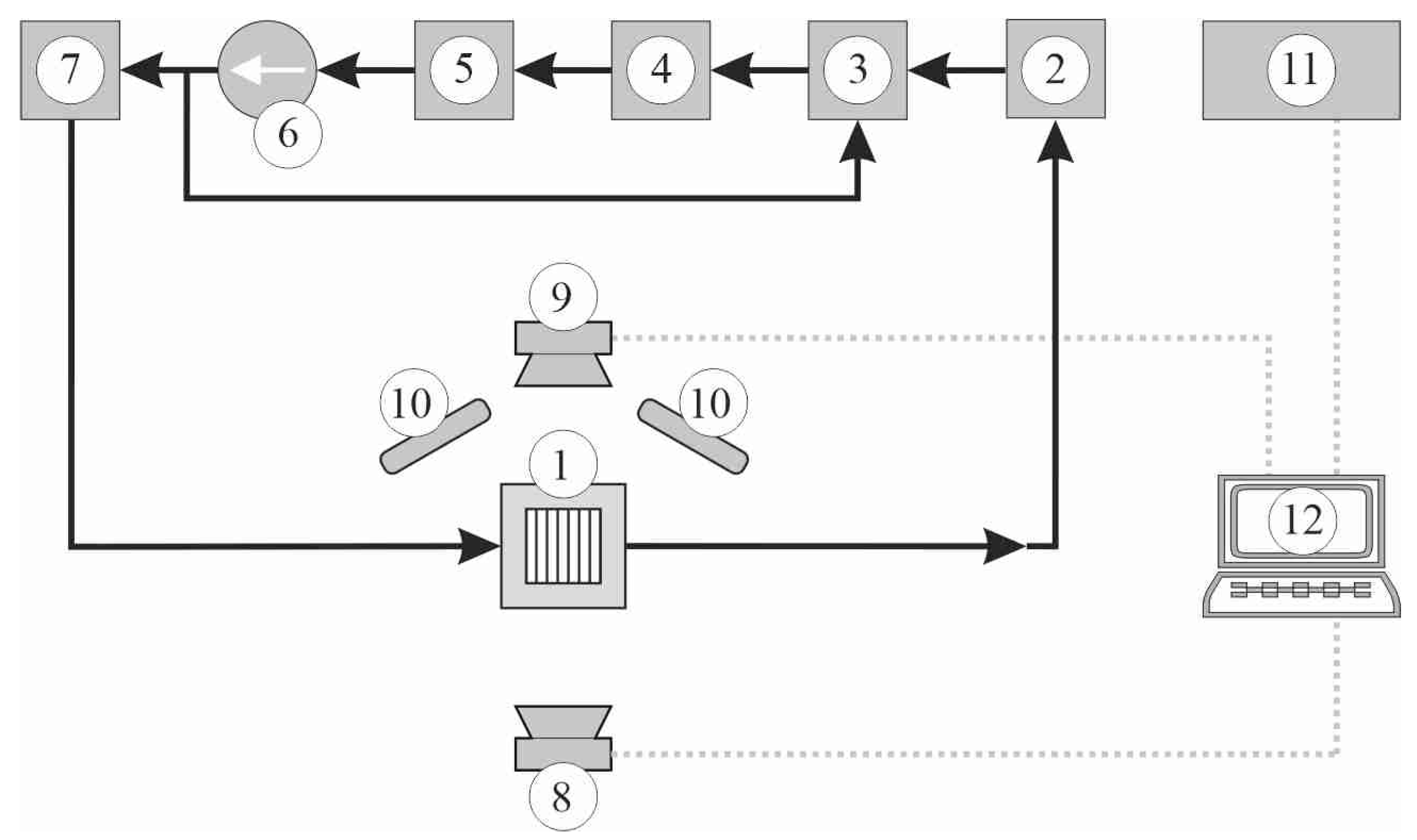
Figure 1. Schematic diagram of the main loops implemented on the test stand: flow circulation loop of working fluid: 1—test section with mini-channels; 2—heat exchanger; 3—compensating tank; 4—deaerator; 5—filter; 6—circulating pump; 7—Coriolis mass flow meter. Data acquisition system: 8—infrared camera; 9—high-speed camera; 10—lighting system; 11—data acquisition stations; 12—PC.
Energies 17 02436 g001
Figure 2. Test section: (a) longitudinal section showing main components of the test section: 1—spacer with system of mini-channels, 2—heating plate, 3—glass plate, 4—inlet/outlet chamber, 5—body, 6—front cover; (b) view of the front cover side of the test section with seven mini-channels.
Energies 17 02436 g002
Figure 3. Selected types of heating-plate wall surfaces in terms of roughness, microscopic image, and 3D topography: (a) smooth surface, (b) laser-textured surface, (c) laser-vibrating textured surface, (d) electro-erosion textured surface, (e) fibrous surface, and (f) powder surface; microscopic image (photo) → 3D topography.
Energies 17 02436 g003
Figure 4. Relative errors of the heat transfer coefficient as a function of heat flux.
Energies 17 02436 g004
Figure 5. The heating plate temperature measurements obtained from the infrared thermography as a function of distance from the mini-channel inlet.
Energies 17 02436 g005
Figure 6. Boiling curves plotted for five specific points within a mini-channel lying in the central axis of the mini-channel.
Energies 17 02436 g006
Figure 7. The two-dimensional fluid temperature distribution obtained by the Trefftz method for: (a) q = 19.5 kW/m2, (b) q = 62.9 kW/m2, and (c) q = 112 kW/m2; the data from the reference experiment.
Energies 17 02436 g007
Figure 8. Heat transfer coefficient as a function of distance from the mini-channel inlet, calculated from Equation (6) on the basis of the data from the reference experiment.
Energies 17 02436 g008
Figure 9. The relationship between the heat transfer coefficient and the imposed heat flux at various distances from the mini-channel inlet; the dependence based on data obtained from the reference experiment.
Energies 17 02436 g009
Figure 10. Heat transfer coefficient as a function of distance from the mini-channel inlet, determined with the use of T-functions and according to the Simcenter STAR-CCM+ programme; both results were obtained on the basis of identical data from the reference experiment.
Energies 17 02436 g010
Figure 11. The HOQ matrix scheme: 1—customer requirements, 2—importance of customer requirements, 3—technical features, 4—relations between customer requirements and technical features, 5—correlation matrix between technical features, and 6—importance of technical features.
Energies 17 02436 g011
Figure 12. Flowchart of the proposed approach.
Energies 17 02436 g012
Figure 13. HOQ matrix created for a compact heat exchanger.
Energies 17 02436 g013
Figure 14. Feature of a compact heat exchanger (a product): material.
Energies 17 02436 g014
Figure 15. Feature of a compact heat exchanger (a product): working temperature depending on properties of the working fluid.
Energies 17 02436 g015
Figure 16. The most common positions of the computer motherboard with possible heat exchanger spatial orientations for cooling electronic components: (a) vertical position of the motherboard: I—upward flow in the mini channels—‘90’ position, II—downward flow in the mini channels—‘270’ position, III—horizontal side channel position (not tested), and (b) horizontal position of the motherboard: IV—‘0’ position; the black arrows indicate possible fluid flow directions.
Energies 17 02436 g016
Figure 17. Feature of a compact heat exchanger (a product): spatial orientation of the mini-channels in a compact heat exchanger.
Energies 17 02436 g017
Figure 18. Feature of a compact heat exchanger (a product): type of flow, which is correlated with the Reynolds number value.
Energies 17 02436 g018
Figure 19. Feature of a compact heat exchanger (a product): type of phase flow.
Energies 17 02436 g019
Figure 20. Feature of a compact heat exchanger (a product): geometrical parameters.
Energies 17 02436 g020
Figure 21. Feature of a compact heat exchanger (a product): developed surfaces.
Energies 17 02436 g021
Figure 22. Completed HOQ matrix created for a compact heat exchanger.
Energies 17 02436 g022
Table 1. The main devices operated on the test stand.
Loop or system/deviceModel of the device (manufacturer, city, country)
Flow loop
Circulating pumpTuthill DGS.99EEET2MM00000
(Tuthill Pump Group, Alsip, IL, USA)
Coriolis mass flow meterEndress+Hauser Proline Promass A 100
(Endress+Hauser Polska, Wroclaw, Poland)
Pressure metersEndress+Hauser Cerabar S PMP71,
(Endress+Hauser Polska, Wroclaw, Poland)
Data acquisition system
Data acquisition stationIOTech DaqLab 2005
(Measurement Computing, Norton, MA, USA)
Data acquisition stationMCC USB SC-1608G
(Measurement Computing, Norton, MA, USA)
Temperature acquisition subsystem
Infrared cameraFLIR A655SC
(FLIR Systems Inc., Wilsonville, OR, USA)
ThermocoupleK-type thermocouple with a sensor diameter of 0.5 mm
(Czaki Thermo-Product, Raszyn-Rybie, Poland)
Image acquisition subsystem
High-speed cameraJAI SP-5000M-CXP2
(JAI Ltd., Yokohama, Kanagawa, Japan)
Electrical subsystem
Inverter welderSpartus ARC ZX7-400B
(Spartus, Miszewko, Poland)
ShuntLumel B2-060400AB0100MA
(Lumel, Zielona Gora, Poland)
AmmeterDataforth 8B32-01 (Dataforth Corp., Tucson, AZ, USA)
+ USB SC-1608G (Measurement Computing, Norton, MA, USA)
VoltmeterDataforth 8B40-01 (Dataforth Corp., Tucson, AZ, USA)
+ USB SC-1608G (Measurement Computing, Norton, MA, USA)
Table 2. Geometric parameters of a compact heat exchanger with mini-channels.
Number of mini-channels in a group791115
Dimensions of each mini-channel in a group (mm)
Length43434343
Depth1111
Width43.321.6
Table 3. Main properties of the working fluids, manufactured by 3M [28].
Fluid,
Manufacturer
Boiling Point, KThermal
Conductivity, W/(m·K)
Density,
kg/m3
Specific Heat,
J/(kg K)
Expansion
Coefficient (1/K)
Dynamic
Viscosity, kg/(m s)
Surface
Tension,
N/m
FC-72
3M Center, St. Paul, MN, USA
3290.057168011000.00160.000640.012
HFE-649,
3M Center, St. Paul, MN, USA
3220.059160011030.00180.000640.0108
HFE-7000,
3M Center, St. Paul, MN, USA
3070.075140013000.00220.000450.0124
HFE-7100.
3M Center, St. Paul, MN, USA
3340.069151011830.00180.000580.0136
HFE-7200,
3M Center, St. Paul, MN, USA
3490.068143012140.00160.000610.0136
Distilled water3730.591998.241870.00210.0010020.0728
Table 4. Characteristics of the surface roughnesses for the main groups of enhanced surfaces of the mini-channel heating wall.
Surfaces/
Parameters
SmoothLaser-TexturedLaser-Vibrating TexturedElectro-Erosion TexturedFibrousPowder
Arithmetic mean deviation
of the roughness profile, Ra
0.1751.0271.3640.61522.61311.283
Arithmetic mean height
of surface roughness, Sa
0.3460.5581.9060.98331.75813.919
Maximum height of surface roughness, Sp3.6439.4299.20010.115155.2859.922
Table 5. Errors of the experimental parameters due to devices.
Experimental Parameter
(Device, Type; Manufacturer)
Error
Temperature of the heated plate
(infrared camera, A655sc, FLIR;
FLIR Systems Inc., Wilsonville, OR, USA)
±2 °C or ±2%
of the reading, −20 ÷ 120 °C
Pressure of the fluid at the inlet to the test section (gauge pressure meter, Cerabar S PMP71,
Endress+Hauser;
Endress+Hauser Polska, Wroclaw, Poland)
±0.05%
of the reading in the range, 0 ÷ 10 bar
Atmospheric pressure
(absolute pressure meter, A-10, WIKA;
WIKA Polska, Wloclawek, Poland)
0.5% of the full scale,
0 ÷ 2.5 bar
Mass flow rate
(Coriolis mass flow meter, Proline Promass A100, Endress+Hauser;
Endress+Hauser Polska, Wroclaw, Poland)
±0.1%
of the reading, 0 ÷ 0.125 kg/s
Temperature of the working fluid
(thermocouple, K-type;
Czaki Thermo-Product, Raszyn Rybie, Poland)
±1.5 °C in the range of −40 ÷ 375 °C,
according to the applicable standard
Table 6. The base data of the reference experiment.
Parameters, UnitValue
Temperature of FC-72 at the inlet, K287.55
Temperature of ambient air, K293.15
Atmospheric pressure, kPa101.32
Inlet overpressure, kPa101.38
Outlet overpressure, kPa101.28
Mass flow rate, kg/h20.76
Heat flux supplied to the heating plate, W64.00
Table 7. The base characteristics of the experiment with full range of parameters.
Parameters, UnitRange of the Parameter
Temperature of FC-72 at the inlet, K287–292
Temperature of FC-72 at the outlet, K289–323
Temperature of ambient air, K293.15
Inlet overpressure, kPa6–57
Heat flux, kW/m219.5–139
Mass flow rate, kg/h20.6–21.4
Disclaimer/Publisher’s Note: The statements, opinions and data contained in all publications are solely those of the individual author(s) and contributor(s) and not of MDPI and/or the editor(s). MDPI and/or the editor(s) disclaim responsibility for any injury to people or property resulting from any ideas, methods, instructions or products referred to in the content.