Article

Lithium-Ion Batteries (LIBs) Immersed in Fire Prevention Material for Fire Safety and Heat Management

1
School of Energy and Chemical Engineering, Ulsan National Institute of Science and Technology (UNIST), Unist-gil 50, Ulsan 44919, Republic of Korea
2
R&D Center, 4TOONE Corporation, UNIST-gil 50, Ulsan 44919, Republic of Korea
*
Author to whom correspondence should be addressed.
Energies 2024, 17(10), 2418; https://doi.org/10.3390/en17102418
Submission received: 18 April 2024 / Revised: 7 May 2024 / Accepted: 15 May 2024 / Published: 17 May 2024
(This article belongs to the Special Issue Advances in Battery Energy Storage Systems)

Abstract

:
Lithium-ion batteries (LIBs) have emerged as the most commercialized rechargeable battery technology. However, their inherent property, called thermal runaway, poses a high risk of fire. This article introduces the “Battery Immersed in Fire Prevention Material (BIF)”, the immersion-type battery in which all of the LIB cells are surrounded by a liquid agent. This structure and the agent enable active battery fire suppression under abusive conditions while facilitating improved thermal management during normal operation. Abuse tests involving a battery revealed that the LIB module experienced fire, explosions, and burnouts with the target cell reaching temperatures of 1405 °C and the side reaching 796 °C. Conversely, the BIF module exhibited a complete lack of fire propagation, with temperatures lower than those of LIBs, particularly 285 and 17 °C, respectively. Under normal operating conditions, the BIF module exhibited an average temperature rise ~8.6 times lower than that of a normal LIB. Furthermore, it reduced the uneven thermal deviation between the cells by ~5.3 times more than LIB. This study provides a detailed exploration of the BIF and covers everything from components to practical applications. With further improvements, this technology can significantly enhance fire safety and prevent the thermal degradation of batteries in the real world.

1. Introduction

Lithium-ion batteries (LIBs) are the most widely commercialized battery technology for their exceptional electrochemical performances, including high energy density and power [1]. However, due to the risk of a characteristic called thermal runaway, fires often occur under harsh conditions (high temperature, high C-rate) or in abnormal environments (improper thermal management) regardless of their application, such as in electric vehicles (EVs), energy storage systems (ESSs), and smart devices [2,3]. These fire incidents arise from the convergence of three factors: heat (exothermic chain reactions to reach the ignition point), combustible components (battery electrolytes and separators), and the presence of oxygen [4,5,6].
Various solutions, such as battery thermal management systems, fire suppression agents, and devices, have been developed to address this problem. Representative solutions are technologies that disrupt battery–oxygen contact and cool the batteries to prevent temperatures from reaching the ignition point [7]. To mitigate oxygen contact, fire suppression materials such as hydrofluorocarbon (HFC) [8,9,10], solid aerosol K2CO3 [11,12], and ABC powder [13] are installed within battery modules or rack systems to suffocate the fire by chemically reacting with oxygen [4,5,13]. For cooling, fire-extinguishing systems are under development, which involve injecting or spraying agents such as Novec 1230 [14,15] or liquid nitrogen [16,17]. These conventional agents can absorb substantial amounts of heat because of their latent heat of evaporation.
However, these methods react only after a fire has already occurred [18]. Owing to the characteristics of battery fires that result in high-energy explosions in random cells, extinguishing fires using conventional agents installed within a system poses challenges. Moreover, in the case of modules or packs in contact with high-density LIB cells, such as ESSs, the speed and scale of fire propagation increase rapidly, further exacerbating the extinguishment [19,20].
To improve the fire suppression performance, the research around immersing the batteries into cooling agents is recently in development. This method not only enables thermal management at all times, as all of the batteries are immersed in the agent, but also overcomes the disadvantage of existing solutions through the immediate agent penetration into the thermal runaway cell. However, the selection of suitable fire-extinguishing agents for conventional immersion-type batteries is limited [21,22,23] because they should not cause corrosion or conductivity issues when in contact with the batteries. The conventional agents, used in immersion-type batteries, have incomplete fire-extinguishing capabilities due to slow heat dissipation caused by low thermal conductivity and heat capacity [9,15,22]. Also, safety concerns are prevalent [21]. So, they are used only to prevent fires through thermal management instead of extinguishing them [24]. Some researchers have developed water-based extinguishing agents [24] that have a better cooling effect than conventional agents; but due to the problems that occur during the immersion mentioned, they were developed only in the form of mist or injections [21,23].
Therefore, we expanded the selection range of fire-extinguishing agents by applying hermetical sealing to the batteries, capable of making batteries safe from the agent, and devised the “Battery Immersed in Fire Prevention Material (BIF)”. In the BIF, all cells within the battery operate while fully submerged in the liquid agent solution, which has an outstanding fire suppression performance through high thermal conductivity and heat capacity. It immediately suppresses fires during abusive conditions and provides enhanced electrochemical performance during normal operation through heat management.
As shown in Figure 1, this study covers the components of the practical applications of BIF.
First, the study explains the components of BIF, such as FPM and sealing materials. The BIF cell and module used for the experiments are designed with these functional components. Second, the single cell at the center of the BIF module was intentionally overheated to test its fire-propagation prevention capabilities, which were compared with those of the LIB module under identical conditions. Third, the performances of cycle life, capacity, Electrochemical Impedance Spectroscopy, maximum discharge C-rate, and temperatures of the BIF are compared with LIB in harsh operating conditions to verify the thermal management effect.
The BIF is a solution for immediate fire suppression and thermal management simultaneously, surpassing the conventional fire suppression methods. This study is expected to contribute to the applications of BIF in the real world such as mobility (e.g., kickboards), ESSs (energy storage systems), and EVs [25].

2. Materials and Methods

In the Materials and Methods Section, components of the BIF, BIF cell, and module used for the experiments and the experiment conditions are explained.

2.1. Components of the BIF

2.1.1. Lithium-Ion Battery (LIB) Cell

The cylinder (18650) type of lithium-ion battery cells (model number: INR18650-30Q) was used in the BIF module. Because cylindrical cells exhibit a lower volume than prismatic or pouch-type cells, constructing modules of diverse shapes and specifications considering series or parallel connections is simple. In this study, 30 LIB cells comprised a BIF module connected in 10s3p and fastened in a 15 × 2 array for application in an electric kickboard (EV).

2.1.2. Fire Prevention Material (FPM)

FPM surrounds the lithium-ion battery via immersion, and this agent is applied in BIF for the fire suppression and thermal management of the batteries. It immediately penetrates into the lithium-ion battery and suppresses fires under abusive conditions. Also, it provides enhanced electrochemical performance during normal operations through effective heat management.
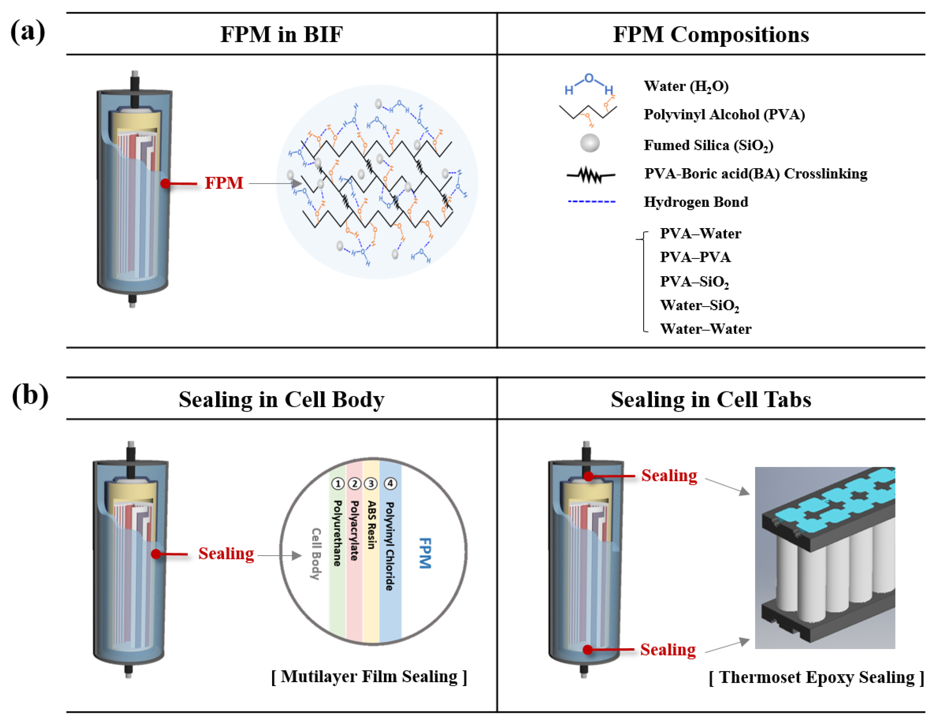
The components of the FPM were selected to have high cooling and oxygen-blocking efficiency. The main component of the material, the water [26] occupying 94% of the FPM, absorbs the heat for thermal management. It has the advantages of heat capacity, high accessibility, manageable treatment, and low cost. The PVA (polyvinyl alcohol) chain, occupying 4% of the FPM, prevents water evaporation and blocks oxygen. Boric acid regulates the pH, and the Sodium Bicarbonate helps the crosslinking of the agents. Additionally, the expanded glass powder is added for film layer coating to the battery at a high temperature (~650 °C) to block the oxygen. When the thermal runaway happens, the FPM starts to absorb the heat and evaporate. After the whole of the water molecule evaporates over 100 °C, the polymer and powder in FPM coat the oxygen-blocking films to the battery. The synthesis method of the FPM is described in the Supporting Materials. Also, the detailed fire suppression process and flame-retardant performances of the FPM are described in Figure S1.
Figure 2a shows the structure and material composition of the FPM applied to the BIF. The polyvinyl alcohol (PVA) chain constructed the backbone of the material, and molecules such as water, boric acid, and fumed silica were crosslinked within. The hydrophilic PVA chain fixes the water molecules and the rest molecules form linkages with each other through hydrogen bonds.
The properties of the FPM are suited for immersion-type batteries [27]. It exhibits a high heat conductivity (0.559 W m−1 K−1), heat transfer coefficient (about 1000 W m−2 °C−1), density (0.94 kg m−3), heat capacity (3.92 J g−1 °C−1), and latent heat energy (2125 J g−1). Due to the high heat conductivity and heat transfer coefficient, FPM can more efficiently absorb the heat emitted from batteries during operation and thermal runaway than the conventional agents as Table S1. At the same time, the high density, heat capacity, and latent heat energy prevent large temperature increases in FPM. The superior material properties of FPM are compared with the other battery fire suppression agents in Table S1.
For the next step, to determine the appropriate quantity of FPM to be incorporated into the BIF, the theoretical amount of FPM required to block the fire was calculated. First, the maximum heat energy generated with the LIB short circuit was calculated (Equation (1)). It differs based on the material and type of cell but is usually proportional to the energy of the battery [28,29].
The heat absorbance of the FPM was then calculated as the sum of the heat required to increase the temperature and the latent heat (Equation (2)). The heat capacity (3.92 J g−1 °C−1) and the temperature difference from room temperature (RT) to the boiling point of the water (100 °C) were calculated. Because the thermal runaway temperature is higher than the boiling point of the FPM, the latent heat of the FPM (2261 J g−1) is considered. Assuming that the energy generated from the short circuit is entirely converted into heat at the room temperature of 25 °C, Equations (1) and (2) yield the same values. Consequently, the 1.48 g/Wh of FPM was applied to BIF. The experiments for verifying these calculations of the required theoretical amount of FPM and its fire suppression performance are performed in Figure S2.
E W h × 3600 J W h = Q ( k J )
3.92 k J k g · × m × 100 R T   ° C + 2.261 k J g ( Q F P M , L a t e n t )

2.1.3. Sealing

Nonetheless, because the primary component of the FPM is water, it exhibits high electrical conductivity. Directly submerging the battery into the FPM results in severe damage, connecting the anode and cathode. The material to prevent direct contact with the battery and the FPM should be applied between them.
Therefore, sealing was applied to the BIF to prevent ingress of FPM from the battery under normal conditions. Simultaneously, it facilitates FPM penetration into the cell through tearing when abuse, such as thermal runaway, occurs. To perform these functions, the sealing should be sufficiently thin for effective thermal conductance during operation and allow direct FPM penetration into the cell for early fire blocking. In addition, to protect cells that would suffer damage from FPM under normal conditions, such as a short circuit due to moisture, the Water Vapor Transmission Rate (WVTR) should be low. Considering these conditions, the sealing covers the entire battery surface and is divided into two parts: the cell body and cell tabs. For effective heat conductance and preventing moisture penetration into the battery, the thin (0.22 mm) and very low WVTR (0.1 g/m2 day) multilayer films composed of polyurethane, polyacrylate, ABS resin, and polyvinyl chloride were applied to the cell bodies, as shown in Figure 2b. Cell tabs, however, require a higher level of sealing than the cell body because of the Ni tab connections in the cell tabs and the sophisticated structure of the cell holder. Therefore, a highly transformable thermoset epoxy (Epons ES-2) with 2.0 mm thickness with WVTR (0.5 g/m2 day) was applied to the cell tabs.

2.1.4. The Else Components

Cell holders were applied to the tabs of the battery cell in the module. They were developed to fix an array of cells and maintain uniform distances between the cells. Furthermore, they were designed to fill the epoxy sealing after spotting nickel tabs onto the cell tabs. In addition, it helps the cells to be immersed in the FPM during operation and under abusive conditions through fixation.
The BMS controls the safety functions, including overdischarge, overcharging, overcurrent, and balancing. It was applied in the BIF module.
The I/O terminal (input and output terminal) was applied to the end of the BIF tab for charging and discharging the battery module with an adequate current.
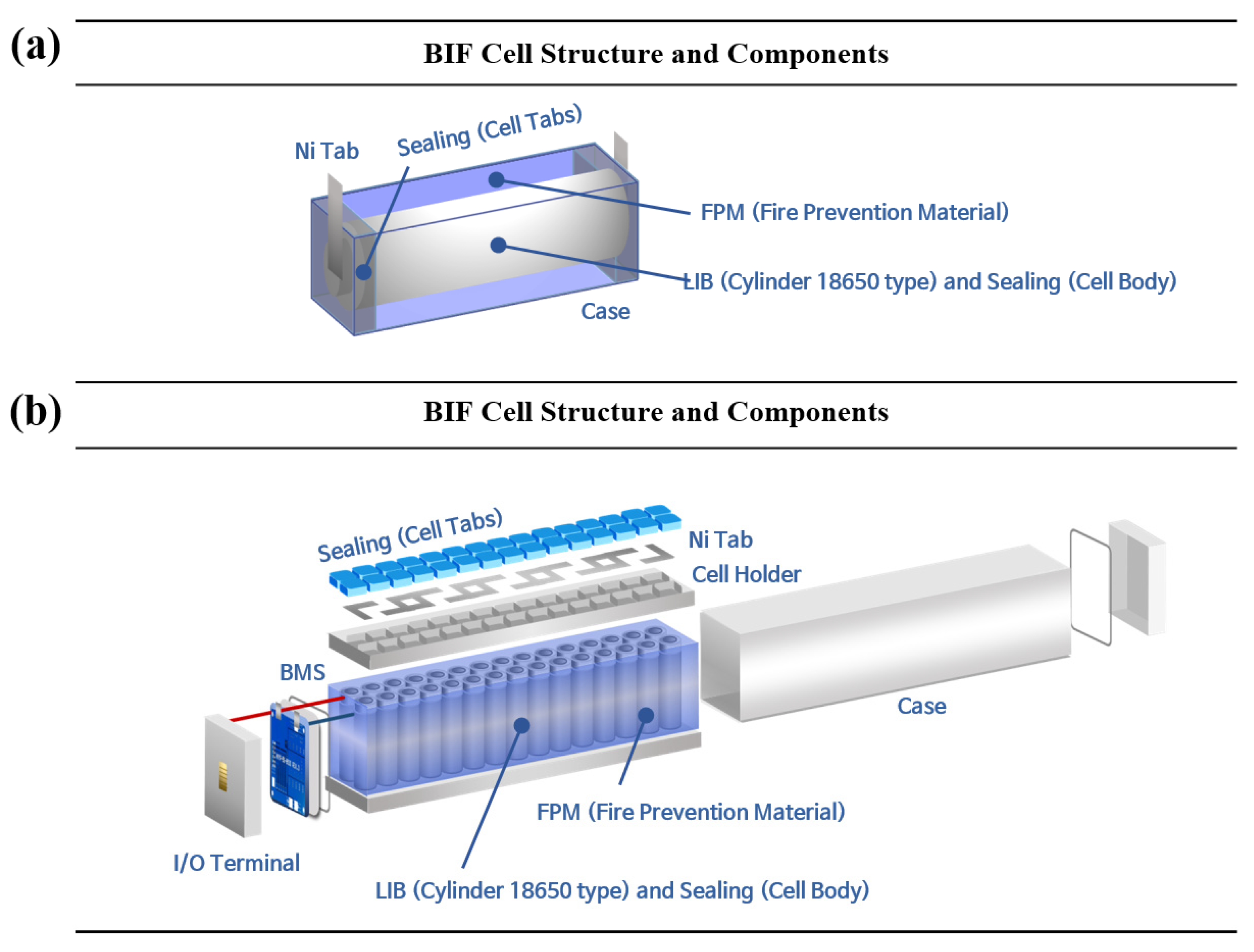
The case was designed to house all of the BIF components in a single unit, called the BIF cell and module. In the BIF cell case, a single LIB cell with epoxy-sealed tabs was immersed in the FPM. In this BIF module case, 30 LIB cells with cell holders and epoxy-sealed tabs were immersed in the FPM.

2.2. BIF Cell and Module

The BIF cell is designed to estimate the electrochemical performances, compared with LIB in harsh operating conditions. For effective fire suppression and thermal management, the immersion fluid (FPM) was regularly brought into contact with the cell body and sealed with multilayer films. The 16.4 g of FPM was brought into contact with the cell at 2 mm intervals from the case, occupying 28% of the total module weight.
The BIF module is designed to have multiple battery cells to measure the heat deviation between the cells in harsh operating conditions and numerically estimate the degree of the blocking of fire propagation when thermal runaway occurs. For effective fire suppression and thermal management, the immersion fluid (FPM) was regularly inserted between all the cells in the module. The 492 g of FPM was inserted into the cells in the BIF module at 2 mm intervals, occupying 21% of the total cell weight.
Figure 3 illustrates the construction and components of the BIF cell and module. It comprises the LIB cell and the functional components of the BIF such as the FPM, sealing, and selectively the other components such as the cell holder, case, BMS, I/O terminal, and Ni tab that allow operation. Table 1 and Table 2 provide the specifications of the BIF cell and module, together with its electrochemical parameters [30], such as the battery, BMS, and operating conditions [27,31,32].

2.3. Experiment Conditions

2.3.1. Thermal Management

To estimate the thermal management performance of the BIF, its electrochemical performances, such as capacity, cycle, Electrochemical Impedance Spectroscopy (EIS), and voltage efficiency, were compared with those of the LIB. All experiments were conducted under harsh conditions (high/low temperature and high current) to imitate the application operation and abuse conditions [33]. The operating temperature was ~40 °C, the charge current was 1 C, the discharge current was 3C/4C, and the voltage cut was 2.8 V/4.2 V. Thermocouples were attached at uniform locations, the center of the cell body, for all the experiments to record the temperatures.

2.3.2. Thermal Runaway Propagation

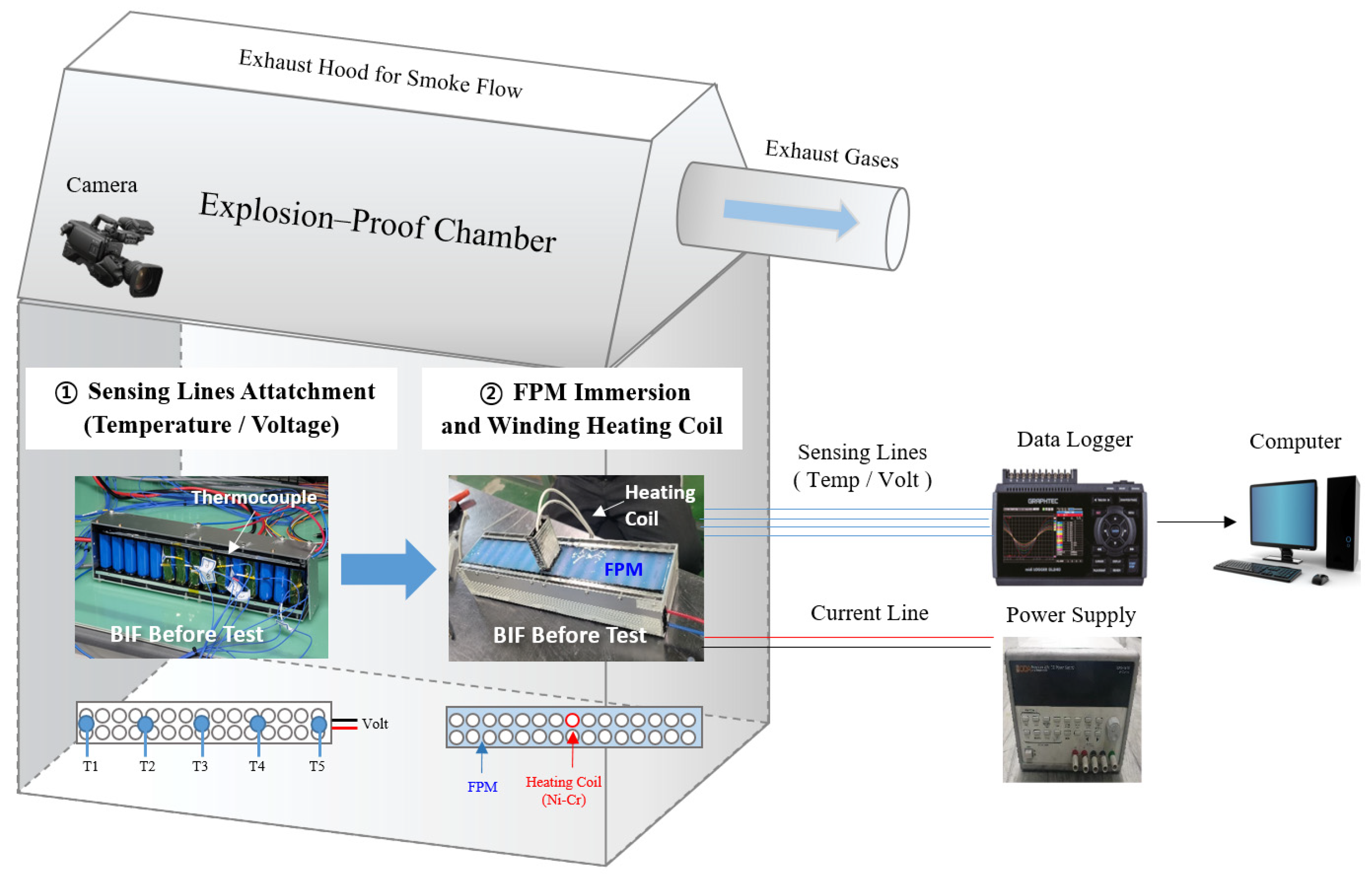
To estimate the fire stability of the BIF module, thermal runaway propagation tests were compared with those of the LIB module as Figure 4. The abuse was induced by overheating a single cell at the center of the module. The trigger cell was winded with a Ni-Cr heating coil, and the maximum sustained temperature was ~350 °C by the power supply. The voltages of the module and the temperature in diverse spots were measured using a data logger. All the experiments were conducted in an explosion-proof chamber for safety purposes.

3. Results and Discussion

3.1. Mechanism and Heat Transmission Diagram with the Governing Equations

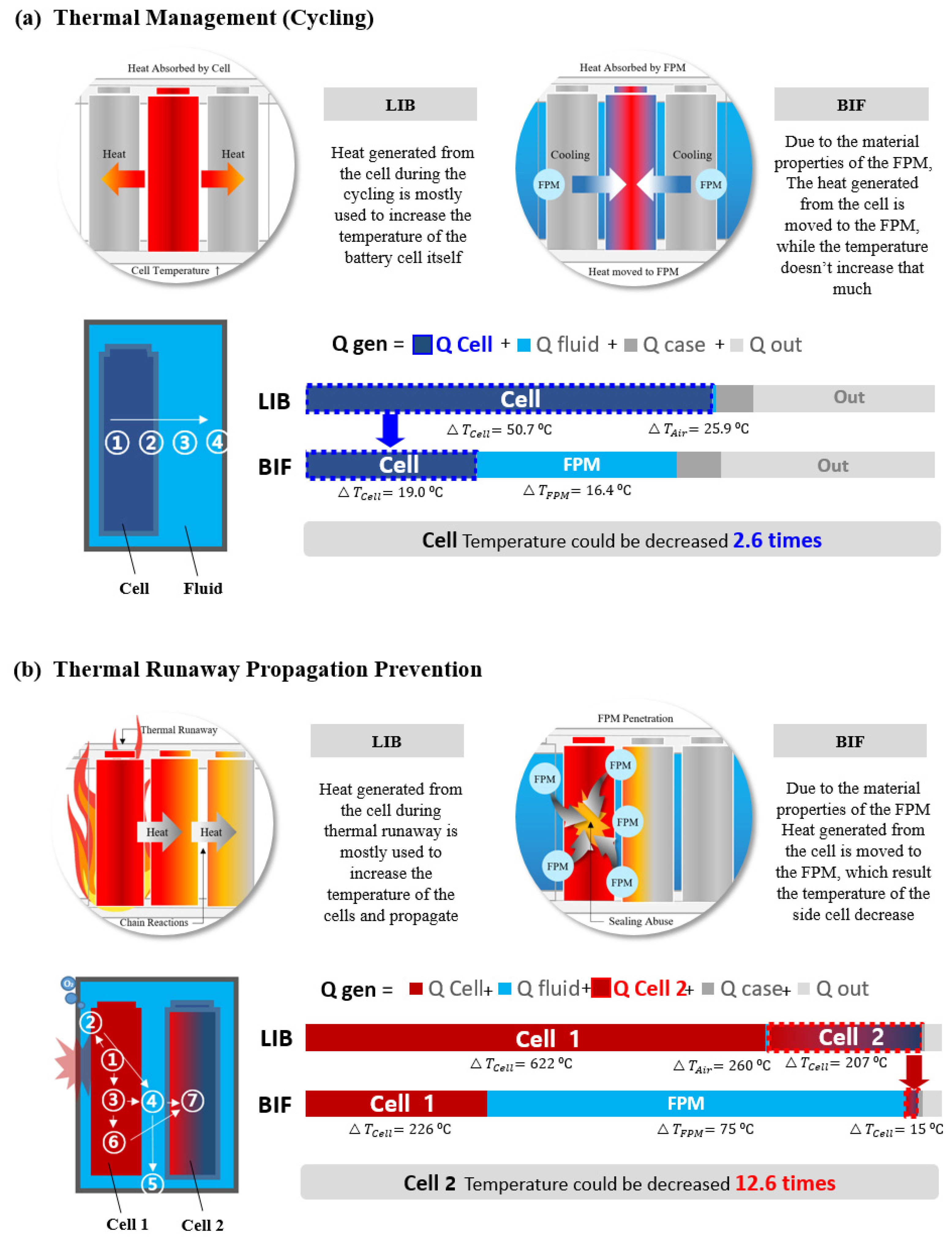
Before the test, the mechanisms through which the FPM on the cell surface in the BIF absorbs heat compared to LIB during thermal management and fire suppression are represented. Then, the process of how the heat generated from the battery cell dissipates and the absorption heat amount of each component are calculated. The 3.7 V/3 Ah/18,650 type cell was used, and the theoretical amount(1.48 g/Wh) of fluid was applied. Thermal management was estimated in harsh conditions (40 °C/3C Discharge and 1C Charge), and the thermal propagation was induced by overheating the cell at 350 °C. Before the abuse test and electrochemical performance estimation in the real environment, the thermal behavior of the LIB and BIF was simulated using the ANSYS Fluent Multiphysics Computational Fluid Dynamics (CFD) simulator in Figure 5. The fluid of LIB is the air, and the fluid of the BIF is the FPM in both thermal management and thermal runaway propagation. The mechanisms and governing equations are as follows.
In Figure 5a, the mechanism by which the FPM on the cell surface in the BIF absorbs heat during thermal management is described below. It shows the direction of heat transmission from the battery to the outside. Rapid heat transfer and small temperature increases are important for efficient heat management [28,29]. Equation (3) expresses the energy conservation related to electrochemistry and thermodynamics. The following parameters were used for the equation: ρ b , the density of the battery (kg m 3 ); C p , b , the heat capacity of the battery (J k g 1 K 1 ); T b , the temperature of the battery (K); k b , the thermal conductivity of the battery (W m 1 K 1 ) ; and Q , G e n , the heat generation of the battery (W) [31,32].
Related to this equation, the heat generated by the battery can be divided into irreversible and reversible heat (Equation (4)). Irreversible heat is generated from the resistance caused by the electron or ion transmission (Equation (5)). It could be driven by the ohmic losses in the battery (ηΩ), the diffusion and migration of Li ions through the electrolyte (ηm), the diffusion of the Li-ion inside the electrodes (ηd), and the charge transfer reactions at the electrode/electrolyte interface (ηct) (Equation (6)). Reversible heat is generated from entropy changes in the electrodes through electrochemical reactions (Equation (7)).
B a t t e r i e s = ρ b c p , b T b t = · k b T b + Q G e n
Q G e n = Q i r r e v + Q r e v
Q i r r e v = I η t o t a l = I E E e q = I 2 R i n t
η t = E   -   Eeq = η + η m + η d + η c t
Q r e v = I T S n F = I T E e q T S o C ,     S = n F E e q T S o C
Subsequently, heat from the battery is applied to the sealing layer using Fourier’s law (Equation (8)). Additionally, heat is transferred to the FPM, which has a heat transfer coefficient ~500 times higher than that of air, according to Newton’s law (Equation (9)) [30,31]. So, the FPM can absorb a lot more heat from the battery cell than air.
    C o n t a c t   S u r f a c e = k b a t t e r y A T n = k s e a l i n g ,     F P M A T n
= k b a t t e r y A T n = h F P M A T b a t t e r y T F P M
The energy conservation of the FPM is expressed in Equation (10). Because it does not include latent heat or flow, the equation can be simplified.
    F P M = ρ F P M c p , F P M T b t = · k F P M T b
Lastly, the heat dissipation equation includes the parameters of T b : the temperature of the battery (K) and ∂T/∂n: the temperature gradient for heat emission (Equation (11)).
    H e a t   D i s s i p a t i o n = k 2 , F P M T n = h ( T F P M T a m b )
Owing to the significantly greater heat capacity of FPM compared to air (about 4 times) and its elevated heat transfer coefficient and density (about 1000 times), it can absorb the heat emanating from the battery efficiently while the temperature of the FPM does not increase that much. This resulting temperature of the BIF cell could be decreased about 2.6 times more than LIB.
Figure 5b illustrates the heat transfer mechanism during thermal runaway in a single-module cell. The principle of transferring the heat generated from the battery to adjacent cells or outside the cell was established sequentially using formulas. To prevent propagation, it is important to decrease the heat reaching the side cells [32]. The heat generated during thermal runaway was divided into released energy and accumulated energy, which were used to increase the cell temperature (Equation (12)).
Heat Generated during thermal abuse = Combustion Heat Release (CHR) + Heat Accumulation (HA)
The energy emitted to the outside of the battery module, called CHR, can be calculated using E, combustion heat released per unit mass of (=13.1 × 10 3   k J   k g 1 ); and m, mass flow of oxygen (kg s 1 ) (Equation (13)).
    C H R = E ( m , O 2 , f l o w   i n m , O 2 , f l o w   o u t )
HA can be calculated using Equation (14), which shows the heat distribution inside the module:
    H A = c b i = 1 n m i , b ( T i , m a x T 0 )
The heat then moves from the cell to the FPM, and (15) expresses the heat absorbance ability of the sensible and latent heat of the FPM. The equation was divided into the heat capacity required to increase the temperature itself (Equation (16)) and the latent heat used for the phase change, which is proportional to the ratio of water (Equation (17)) [33,34].
    F P M   H e a t   A b s o r b a n c e   [ J ] = Q F P M , S e n s i b l e + Q F P M , L a t e n t
Q F P M , S e n s i b l e = C p . F P M · m F P M · T F P M
Q F P M , L a t e n t = Q W a t e r , L a t e n t · 0.946 = r w a t e r · m w a t e r
Finally, the heat exiting the battery can be expressed using Equation (18).
    H e a t   O u t = Q C e l l , O u t = h · A C e l l · T ( C e l l a i r )
Immediately after the thermal runaway, the residual heat inside the battery module can be expressed as Equation (19): A r , the battery cross-sectional area, and T i y , the axial temperature distribution of the batteries, are the required parameters. The relationship between the heat dissipation of the battery module (Hdis), the heat accumulated at the beginning of the FPM reaction (HAstart), and the thermal runaway heat generated during FPM application (HATR) can be written as Equations (20) and (21).
    H A r e = i = 1 n ρ b A r c b ( T i , ( y ) T 0 ) d y
  H d i s = H A s t a r t H A r e + H A T R
H A T R = m i , b c b ( T i , m a x T i , s t a r t )
Finally, thermal runaway propagation occurred when the temperature and heat exceeded the critical temperature point (c1). The parameters used for Equation (22) are C1, critical control temperature for the battery module (K); C2, critical control temperature for a single battery (K); Ph, battery heating power (W); Pt, heat transfer power (W); Pb, FPM cooling power on a single battery (W); and Fc, cooling factor (to determine the inflection point).
    T R P   w h e n T c 1 T c 2 c b m b   d T t ( T c 1 ) t ( T c 2 ) ( P h + P t P b ) d t
To summarize, when thermal runaway happens, an abundant amount of heat (about 17 times) is generated in a short time (about 0.002 times) compared to thermal management. The FPM can efficiently absorb the heat generated from the thermal runaway cell than air as the heat absorbance is 2432 J/g, and 1 J/g each. This resulting temperature of the side cell of BIF could be decreased by about 12.6 more times than LIB.

3.2. Thermal Runaway Propagation Test

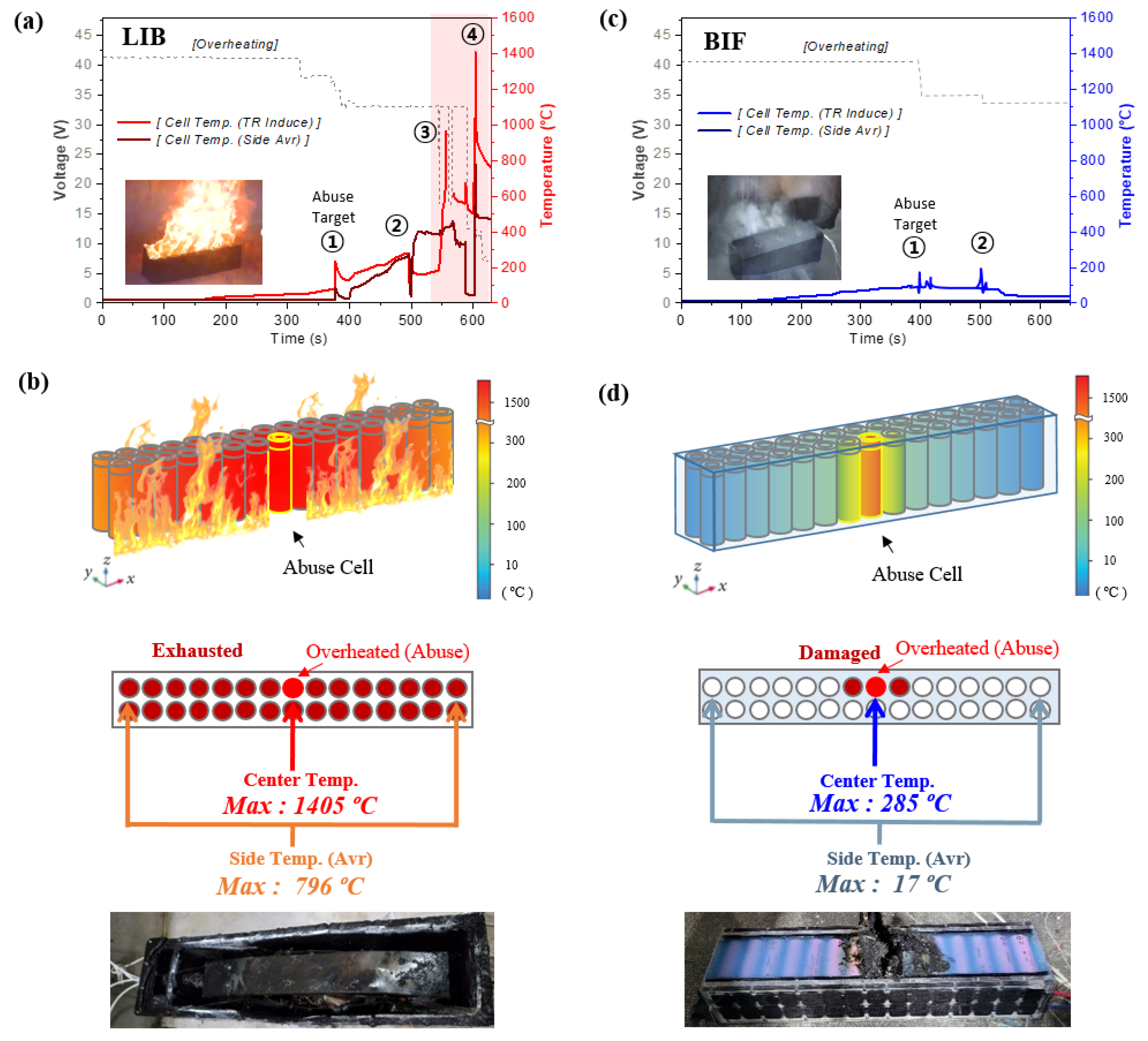
To estimate and compare thermal runaway propagation between the LIB module and the BIF module, a single cell in the center of the module was overheated to induce thermal runaway [34,35,36]. For overheating, the heating coil, composed of nickel and chromium, was winded to the abuse cell and heated over 350 °C using the power supply equipment. The temperatures and voltage of the modules were recorded to estimate the thermal runaway propagation scale, and the temperature-sensing lines called thermocouples were attached to the cell body at the center of the module and the side parts of the module. The results of step time to lead thermal runaway, sudden temperature increase, and propagated cell amount are numbered in Table 3, when thermal runaway occurred via target cell abuse and propagations. In the LIB module, the abuse cell drove thermal runaway propagation step-by-step [37,38], and finally, all the cells suffered exhaustion [39]. However, direct FPM penetration into the abuse target cell in the BIF module prevents extensive propagation. The thermal runaway reactions of the battery by stage are described specifically in Figure S3.
Figure 6a shows the temperatures and voltages of the LIB module with respect to time. When heat accumulated and the temperature of the abuse cell increased over 100 °C, the abuse cell suffered a thermal runaway. The sudden temperature increase was ~153 °C, while the abuse happened within 377 s. The module experienced a large fire with an explosion. Thereafter, continuous fire led to the propagation of TR to the side cells. As thermal runaway propagated, the step time leading to the explosion was shortened. In addition, the number of cells simultaneously suffering thermal runaway radically increased as the fire propagated.
As shown in Figure 6b, the temperature gradient map of the LIB module was constructed when the abuse target cell reached the maximum temperature during the experiment. The maximum temperature of the center cell was ~1405 °C, while the average temperature of the side parts of the module was ~796 °C. These temperatures were sufficiently high to propagate the thermal runaway if there were other modules located beside it. In addition, a photograph of the entire exhausted module, caused by thermal runaway propagation, is shown in the figure.
Similarly, Figure 6c shows the temperatures and voltage of the BIF module with respect to time. The time taken to reach thermal runaway for the abused cell in the BIF module was similar to that of the LIB module at 396 s. However, the sudden temperature increase decreased by ~32% without the fire or explosions due to the direct FPM penetration into the abuse cell. Thereafter, the BIF module suffered thermal runaway once and only the venting gas was observed for the whole experiment.
As shown in Figure 6d, the temperature gradient map of the BIF module was constructed when the abuse target cell reached the maximum temperature during the experiment. The maximum temperature of the center cell was ~285 °C while that of the average temperature of the side part of the module was ~17 °C. This temperature was sufficiently low to prevent thermal runaway propagation from the module in contact with the side. When one side of the BIF case module was opened after the test to determine the extent of the damage, only the batteries that were in direct contact with the abused cell suffered thermal runaway (1 ea) and slight damage (1 ea). Any other damages of the case or leakages did not occur.

3.3. Heat Management Efficiency during the Operation

High C-rate operation is required for applications, particularly in EVs, but the life cycle of LIB significantly decreases at high C-rates and temperatures [40,41,42]. Under extreme or harsh conditions in LIB applications, temperature measurements are used to determine the degree of heat management and estimate the available capacity (life) of the battery per cycle. Therefore, the heat management of batteries is important because the battery temperature during operation significantly impacts battery aging and performance [31,43,44], the fields where active research is being developed. As an example, the research of polydopamine regulation [45] or covalent organic framework with sulfonic acid groups [46] to Zn metal anode is currently being developed to solve this problem.
The high temperatures lead to a side reaction of SEI film formation with thickening, binder decomposition, and electrolyte decomposition [31,43,44]. These affect several degradation modes such as a loss of lithium-ion inventory, anode/cathode active material, electrolyte, and resistance increase. Then, these finally affect capacity and power fade [31,43,44]. The detailed experiments with this are held in the capacity fading and EIS test as follows.
The thermocouple was attached to the center of the cell body to record the temperature while charging and discharging the battery. Consequently, the surface temperature of the LIB cell increased significantly, and life expectancy decreased dramatically as the cycle progressed. In the BIF cell, the surface temperature was maintained and exhibited only slight degradation during long-term operation. The electrochemical performance of the BIF cell was improved through the heat management effect, owing to the heat absorption of the FPM.
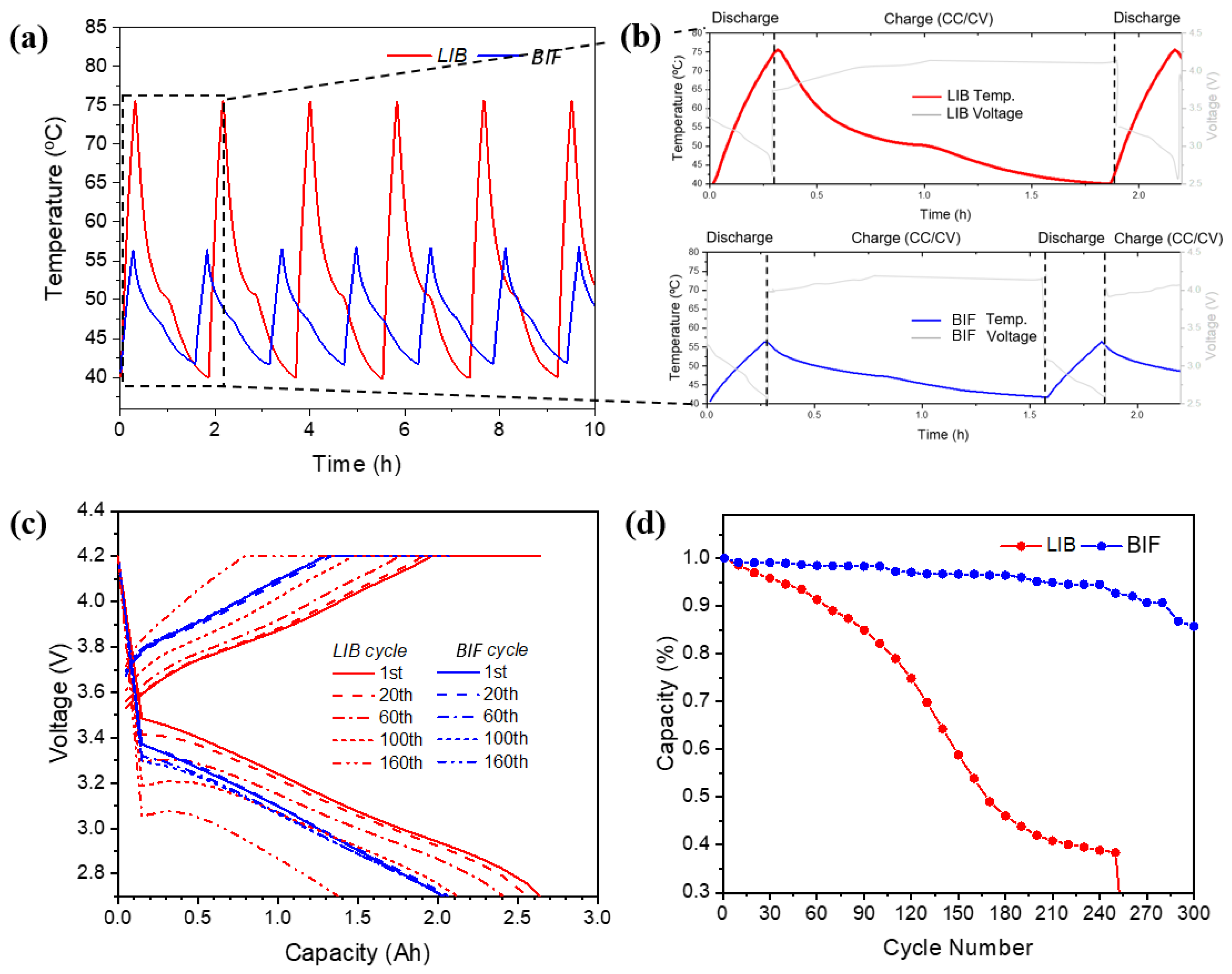
Figure 7a shows the temperature changes in the LIB cell and BIF cell by cycle at a 40.0 °C 3C-rate discharge. Under the same conditions, the surface temperature of the LIB cell increased from 40.0 to 75.6 °C, while that of the BIF increased from 40.0 to 56.3 °C. Two main reasons exist for the temperature increase gap decreasing by ~2.2 times in the BIF cell. First, the increase in temperature decreased primarily because of the specific heat absorbance ability of the FPM. Second, the difference in capacity (heating reaction) time owing to thermal management reduces the temperature increase [47]. The maximum peak temperature was maintained as the cycles progressed.
Figure 7b shows the temperature changes in the LIB cell and BIF cell during cycling. During discharge, the exothermic reaction, activation polarization at the beginning, and concentration polarization at the end rapidly increased the current [48,49,50,51]. At this time, the impedance of the cell increased and decreased significantly in the constant-voltage charge step compared to the constant-current charge. These factors account for the temperature variations [52].
Figure 7c compares the voltage of the LIB cell with that of the BIF cell based on the capacity. In LIB, as the cycle progresses, horizontal and vertical extrapolations occur quantitatively [31,53]. High currents lead to high overpotentials with increasing temperature. The capacity of the LIB cell was better than that of the BIF in the initial cycles owing to the high temperature. However, the capacity of the LIB cell becomes lower than that of the BIF cell after the 100th cycle. Additionally, fluctuations may occur in the early battery charging and discharging processes if the entropic heat negatively affects the driving conditions of certain batteries [31].
Figure 7d shows the capacity by number of cycles. The capacity of the LIB cell exhibited nonlinear aging [54] and rapidly decreased approximately after 100 cycles. This aging is caused by the degradation of internal battery components [32,55]. Battery capacity fading is caused by an increase in internal resistance as the material capacity decreases, such as the reaction between electrodes and electrolytes, reduction in active lithium ions, loss of electrons, and gas evolution [56,57]. This can be further accelerated at high temperatures [32]. Structural disorder, particle cracking, and the loss of electrical contact with the active materials may also be affected [56,57]. However, the BIF cell maintained its capacity as the cycle progressed due to thermal management, unlike the LIB cell.
An additional experiment in harsh conditions (low temperature) is referred to in Figure S4.

3.4. Electrochemical Impedance Spectroscopy (EIS) Comparison

Through impedance estimation, determining the degree of damage to each part or component of the battery in thermal management experiments is possible [58,59,60,61,62,63,64]. Electrochemical impedance spectroscopy was used to estimate the resistance by cycle [32,60,65,66]. Through this experiment, it is possible to know how much the thermal management effect of BIF prevents the aging of the components and increases its lifespan during the charge and discharge cycle.
A normal LIB EIS in a Nyquist plot is usually composed of the bulk resistance of the cell (Rb), such as electrolytes, separators, or electrodes; the resistance and capacitance of the interfacial layer (RSEI/CPESEI); kinetics; charge-transfer resistance; double-layer capacitance (Rct/CPEct); and diffusional effects of the lithium-ion on the host material (W). The nickel–cobalt–aluminum (NCA) battery used in this cell has the advantages of high capacity and disadvantages such as structural and thermal stability, low inverse resistance to charge transfer, a short life cycle, and low resistance to microcracking [67,68,69] in the second semicircle (Rct: charge transfer resistance).
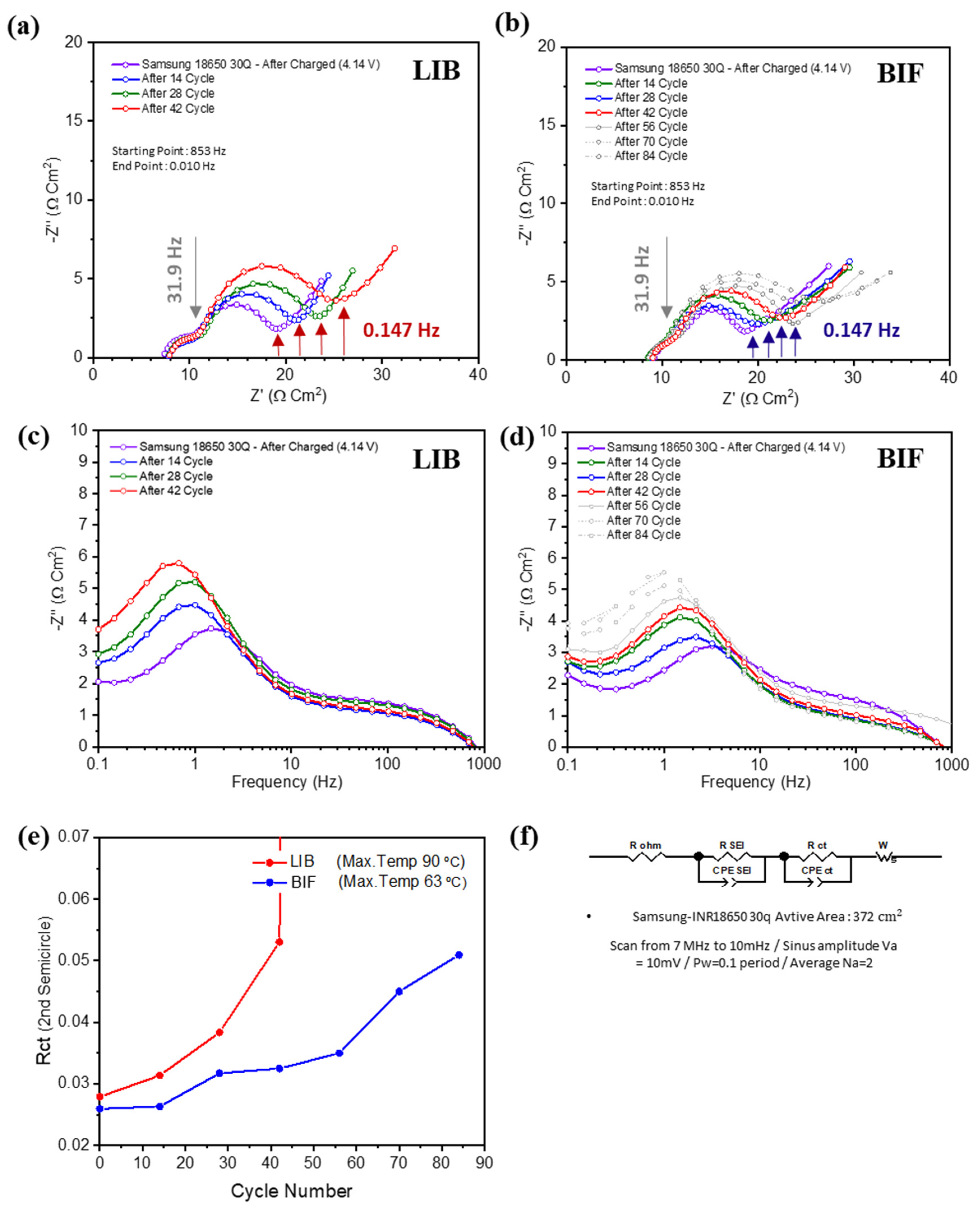
As shown in Figure 8a, the LIB cell ceased operating after 45 cycles. In the BIF cell, the increased range of the second semicircle decreased considerably and operated for more than 84 cycles, as shown in Figure 8b. These ranges were compared between the BIF cell and LIB cell at a frequency of 0.147 Hz. The estimated values are provided in Table 4; in Cycle 42, the increased range of the second semicircle decreased in BIF by ~3.84 times [70,71,72]. Additionally, the cycle life of the battery increased by more than two times in the BIF compared with that in the LIB.
The detailed mechanisms of how the battery in the tests suffered damages are summarized in Figure S5 and detailed explanations are as follows through EIS results.
Because of the short operation time, aging caused by heat is difficult to detect, which prevents side reactions caused by electrolyte decomposition and decreases ion conductivity [32,53]. In addition, the temperature was well controlled in this experiment to limit exterior conditions. This resulted in bulk resistance (Rb) remaining constant in both the LIB cell and BIF cell.
The capacity of the NCA battery decreased before double-layer formation; thus, the differences in the first semicircle (RSEI: interfacial resistance) caused by electrolyte decomposition were not large [56,73]. Generally, based on the Arrhenius equation, the charge transfer resistance decreases as the temperature increases. However, the maximum temperature of the LIB in this experiment was ~90 °C, and a reaction of the electrolyte with Li, decomposition, and gas evolution occurred. This high temperature and C-rate led to a capacity decrease with aging from ~2805 to 2546 mAh [57]. These factors likely increase the second semicircle (Rct: charge-transfer resistance) [67,74].
In the LIB, the cell operation ceased even though the maximum temperature was 90 °C (Internal Battery Protective device, PTC operating temperature was ~100 °C). Electrolyte decomposition may have caused the protection device to operate because of continuous gas or byproduct generation. Therefore, as the cycle progressed, the impedance of the LIB increased substantially. The CID, built inside the 18650, can be operated at a pressure approximately twice or lower than that of the top vent (1 MPa compared to 2.58 MPa) to detach the cathode contact and stop cell operation (XCT of the LIB was measured in the 3C/1C test, as shown in Figure S10) [18].
In summary, high temperature and current led to a Li reaction in the electrolyte, and dissolution led to gas evolution. This led to structural disordering and capacity fading but not to side reactions such as SEI layer formation and electrode oxidation.
As shown in Figure 8c,d, the Bodet graph was used to plot concentration changes with frequency. In the Bodet graph, a peak shift occurred at a low frequency (approximately 1 Hz, mass transport) during cycling. When mass transport or conductivity is low, the peak generally shifts to the left and upward. In the BIF cell, the increased range of the peak shift was approximately twice as small as that in the LIB cell.
The data were applied in Z-view, the impedance fitting program, using an equivalent equation model and circuit equations; the resulting graph is shown in Figure 8e. The life cycle of the BIF cell was two times better, with a slope three times lower than that of the LIB cell, which had a logarithmic shape [60]. Even though the expressed capacity of the BIF cell was lower than that of the LIB (2.5 Ah compared to approximately 2.8 Ah, ~86%) cell, the capacity retention rate was ~1.4 times higher [51].
Figure 8f represents the equivalent model used for fitting the impedance data [75,76], the active area of the single cell used in the module and experiments, and experimental conditions for estimating the impedance [77].

3.5. High Current Performance Comparison Using Pulse Test

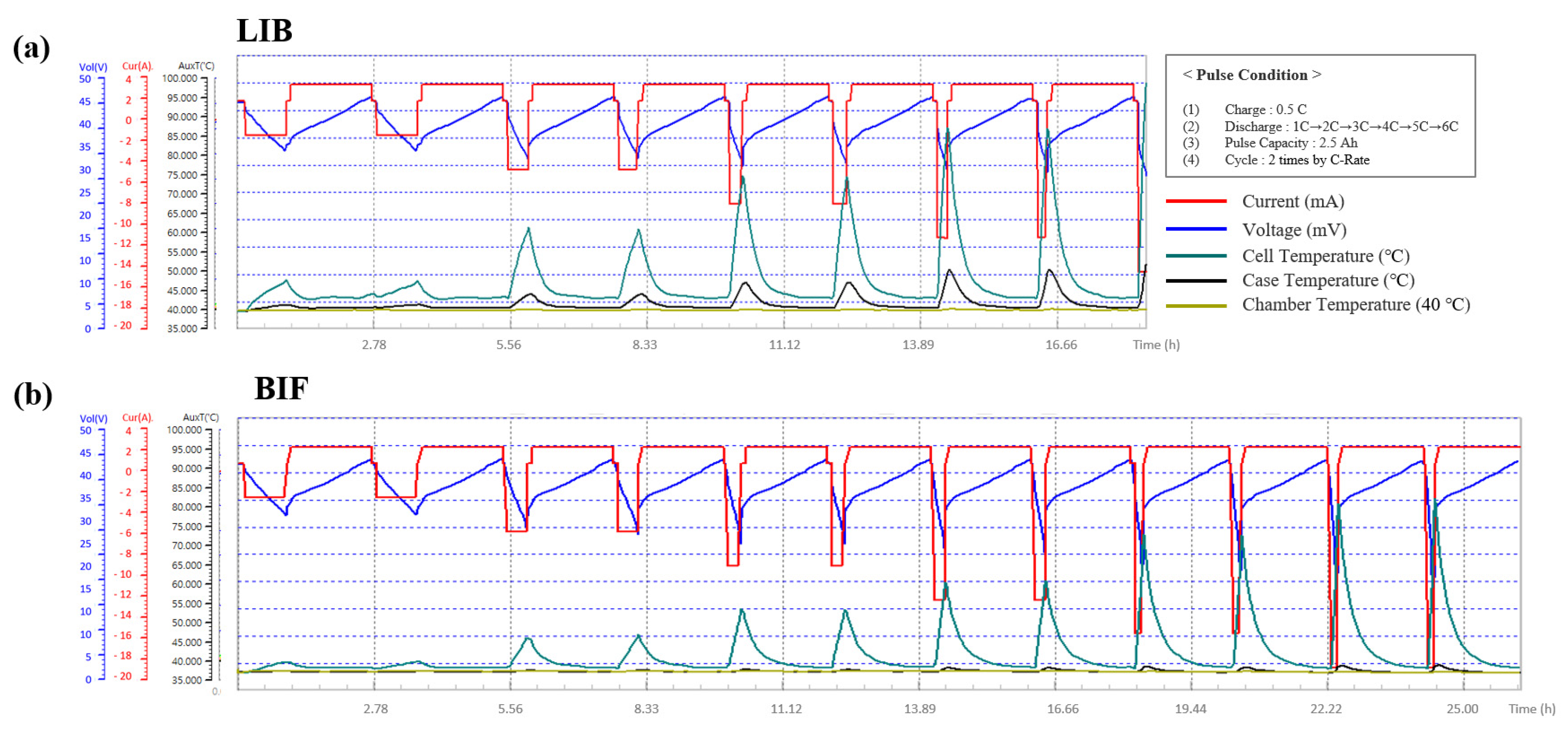
Available power and resistance measurements under extreme operating conditions are important for LIB applications [5,42]. The C-rate, in particular, determines the performance [48]. Therefore, charging and discharging pulses have been applied to both LIB cells and BIF cells for a short period [78]. Under the pulse condition described in Figure 9a, the pulse capacity was 2.5 Ah. To maximize the effects of the discharge reaction, which is an exothermic reaction, the cell temperature was increased, the discharge C-rate was increased gradually from 1C to 6C, and the charge current was fixed at 0.5 C. The voltage and cell temperature were measured, and two cycles occurred at each C-rate for both LIB cells and BIF cells.
In the pulse test, the resistance (ohmic and non-ohmic) and high-power stability of the cell were used as the outputs. In addition, voltage and temperature were measured hourly at 40 °C for extreme environmental high-power verification [31,32].
As shown in Figure 9a,b, the surface temperature of the LIB cell increased considerably, whereas that of the BIF cell was low. As the discharge C-rate gradually elevated, the temperature gap between the battery cell and the case increased, and the maximum temperature gap between the LIB cell and BIF cell also increased. According to Table 5, the maximum C-rate achieved with the BIF was ~6, whereas that of the LIB was ~4. The maximum temperature of the BIF was ~87 °C at 6C, while that of the LIB was ~105 °C at 5C, which ceased the battery operation [48]. At a C-rate of 4C or less, the voltage change (resistance) of the BIF cell was greater than that of the LIB cell, indicating that the voltage efficiency was lower than LIB. This is because the high temperature of the LIB prevented a voltage drop.
This allowed the LIB to easily reach 100 °C, the temperature where protection devices such as PTCs operate, as shown in Figure S10. This prevents the battery from leading to thermal runaway by stopping the battery operation.
Through thermal management, the operating current range of the BIF cell was increased. Therefore, operation over a wide current range was made possible.
Additional detailed information such as voltage differences and resistances at each C-rate is described in Figures S6 and S7.

3.6. Module Temperature by Spots

In multiple cell arrays, such as battery modules or packs, the internal status of the cell, including its capacity, resistance, state of charge, and health, may differ in each cell [79]. Additionally, exterior effects, such as varied temperature and contact resistance, affect the current deviation and decrease the battery performance [7,80]. The temperatures and voltage profile of the BIF module during normal operations are shown in Figures S8 and S9. The performance of the modules gradually decreases as the cycle progresses, owing to cell deviations [81]. These phenomena in cell arrays are called imbalances (or unbalancing).
The imbalance increases when the temperatures of the cells comprising the battery in the module are different [55,82]. Figure 10a shows the maximum temperature of the LIB module while cycling the battery at a 0.5 C-rate. Fifteen spots (the center of the cell body in each spot) of the module were measured during operation. This configuration shows the temperature-fitting diagram of the LIB module at the same time as that of the BIF module. The temperature significantly increased at the center of the module, whereas that at the side was low [67,83]. Figure 10b shows the same experiment performed in the BIF module. Because the temperature increase range was smaller than that of the LIB module through thermal management, the thermal deviation between the cells was minor.
Figure 10c shows the temperature of the LIB and BIF modules by spot during the cycle at 40 °C. In the BIF modules, both the maximum and cell temperature deviations decreased, and the gap between the maximum and minimum cell temperatures was smaller than that in the LIB module. The maximum cell temperature of the LIB module was ~50.1 °C, whereas the minimum cell temperature at the same time was ~45.4 °C. The temperature gap was ~4.7 °C. Concurrently, the maximum cell temperature of the BIF module was ~41.2 °C, and the minimum cell temperature was ~40.5 °C. In the BIF module, the temperature gap was ~0.7 °C, 2.8 times smaller than that of the LIB module.

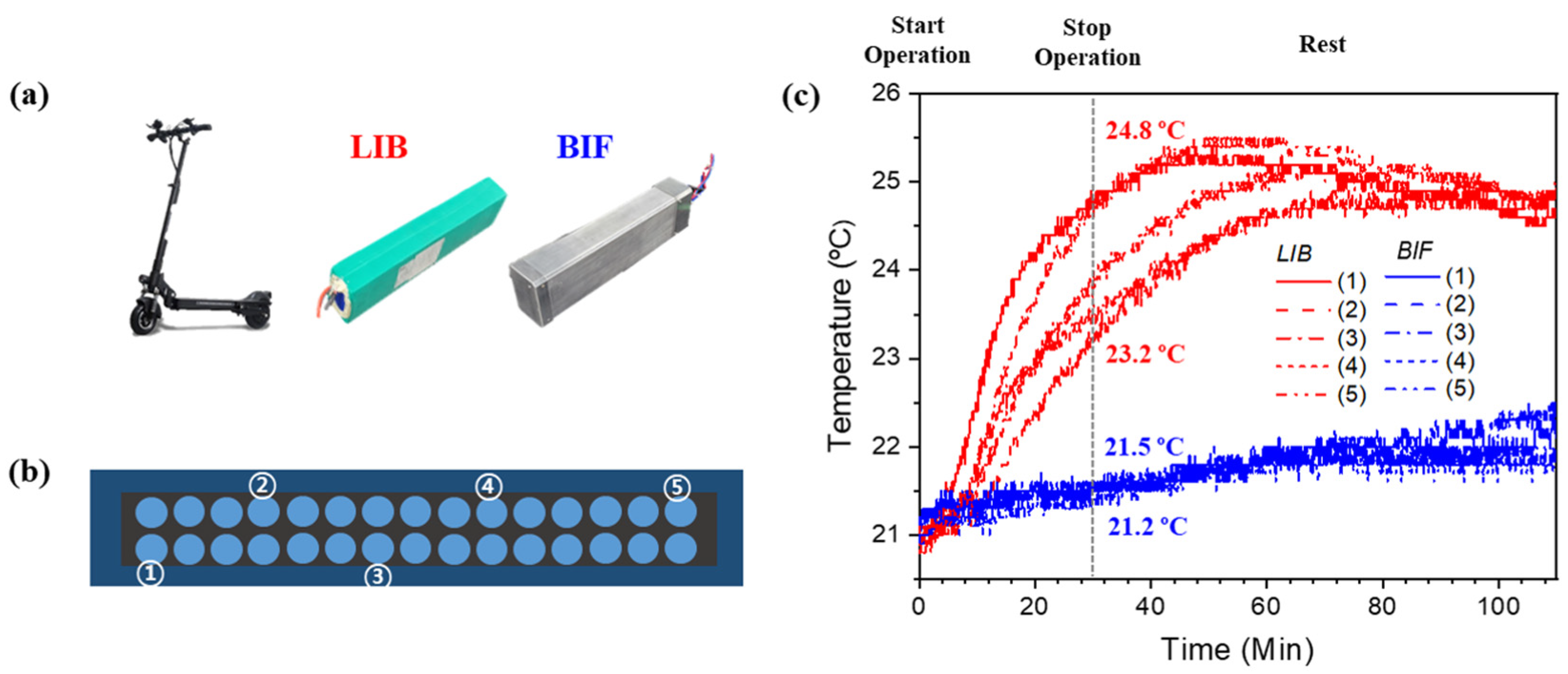
3.7. Module in Application (Kickboard)

As shown in Figure 11a, an electric kickboard was used to realize the performance of the BIF in the module, which was compared to that of the LIB module. The model of the kickboard was a Red Wing Black by Autech.
Figure 11b illustrates the five spots of the thermocouples attached to both the LIB and BIF modules. Owing to the structure of the LIB module, temperature-sensing lines were attached to the surface of the module.
Figure 11c shows the temperatures of the LIB and BIF modules by spot during the kickboard operation. The temperature of the module was ~21 °C right before operation. The kickboard was operated continuously at 1.55C (maximum C-rate) for 30 min. During operation, the temperatures of the LIB and BIF modules increase [84]. However, the temperature of the LIB module varied substantially by spot, whereas that of the BIF module exhibited only minor differences. The maximum temperature of the LIB was ~24.8 °C, while the lowest cell temperature at that time was ~23.2 °C. In the BIF module, the maximum temperature of the cell was ~21.5 °C, while the lowest was 21.2 °C. As a result of the module cycle, not only did the BIF prevent a module temperature increase but it also lowered the temperature gaps of the cells through thermal management.
That being said, after the operation, the temperature of the LIB module in the kickboard continued to increase for ~30 min. Although it was not operating, the power of the BMS, residual heat, closed structure, and exterior environment were affected by the increment of the temperature. Thereafter, the temperature of the entire cell in the LIB began to decrease smoothly, and the temperature gap between the cells decreased. However, the temperature did not return to the initial value. The mobility applications that utilize batteries often require high power (more than a C-rate of 4) in extreme conditions. If the module was operated at a high C-rate, the continuous cycle of this operation may have overheated the battery module during real operation, which significantly affected the electrochemical performances and safety.
The temperature of the BIF module also increased after operation for the same reason as that for the LIB. However, the slope of the temperature increase significantly decreased compared to that of the LIB module, owing to the large heat capacity of the FPM. The temperature of the module began to decrease later than that of the LIB module. The temperature continued to increase at a few points of the BIF module, whereas at others it started to decrease. These improve the capacity and safety of the battery.

4. Conclusions

This study proposes a BIF as a solution to address battery fire risks while facilitating effective heat management. The BIF cell and module were developed and thoroughly investigated, including its components, construction, and potential applications.
Notably, the BIF module effectively mitigated the size of explosions and fire occurrences by impeding the propagation of thermal runaway. This is because the FPM in direct contact with the battery, by immersion structure, can immediately penetrate into the battery when thermal runaway occurs. With significantly lower temperatures observed in the side sections of the cells during such an experiment, it is anticipated that large-scale battery applications such as ESSs will face minimal risks of fire or exhaustion.
Simultaneously, the BIF module enables superior thermal management compared with the LIB module, particularly in extreme environments at all times. This feature enhances battery life and reduces the thermal deviation between cells caused by high currents. In addition, it has the advantages of reducing maintenance costs and being eco-friendly compared to air conditioners that consume power and emit greenhouse gases.
Although further numerical comparisons with other systems are needed, performance efficiencies of the BIF are expected to be high due to the superior agent and immersion structure. These exceed the battery cooling parameters, such as heat capacity, conductance, reaction speed of the agent, and its effecting area on the battery.
This study lays the foundation for future investigations of BIF and their integration into practical battery systems. Further studies are warranted to advance the commercialization of BIF.
First, research on the functional components of BIF, particularly FPM, should be conducted. Establishing the precise mechanisms through which FPM suffocates fires and diminishes heat is essential. Furthermore, improvements in the FPM composition should be pursued to enhance thermal management capabilities, including heat conductivity and capacity, thereby optimizing the performance of the BIF.
Second, in-depth research is required on sealing layers that block FPM penetration completely. Developing a structural design with a thin sealing layer in the form of housing that surrounds the FPM can not only enhance the fire suppression performance but also provide a favorable structure for battery insertion.
Third, the efforts must be directed towards addressing the challenges associated with energy density reduction in BIF. The incorporation of functional elements leads to a reduction in energy density compared with conventional LIBs. Thus, strategies to minimize the amount of FPM while considering thermal management, fire suppression, and specific application requirements should be explored. This necessitates research in areas such as thermodynamics, electrochemistry, simulation techniques [85], and three-dimensional heat flow equations over time and dimensions, as well as the consideration of different LIB cell types (cylindrical, prismatic, or pouch) and their arrangements within the module [86].
Finally, experimental methodologies should be developed to estimate the real battery applications on a larger scale, such as ESSs. This would involve investigating operational methods and conditions such as the presence of a BMS, module stacking configurations, applied applications, and the flow of FPMs. If the BIF is successfully applied to ESSs, it is expected to increase the battery charging rate by replacing fire extinguishing facilities, simplifying cooling systems, and securing stability.
By improving these research areas, the potential of BIF as an advanced battery technology can be realized.

Supplementary Materials

The following supporting information can be downloaded at: https://www.mdpi.com/article/10.3390/en17102418/s1, Figure S1: (a) Fire Suppression Process of the FPM when thermal runaway happens in battery (b) Flame emission Test on a normal paper sheet and the sheet with the FPM (c) Fire suppression test by injection of water and the FPM; Figure S2: Maximum energy generated by LIB short circuit, and the heat absorbance performance of BIF when theoretical amount of the FPM is applied to the cell (3.7 V/50 mAh/LCO Pouch cell); Figure S3: Exothermic chain reactions of LIB by thermal runaway stages; Figure S4: Capacity by cycle and voltage efficiency comparison between LIB and BIF at low temperature (5 °C); Figure S5: Influencing factors and degradation mechanisms of BIF during cycling; Figure S6: Delta V comparisons with gradual C-rate increases for LIB and BIF; Figure S7: Resistance comparisons by gradual C-rate increases of LIB and BIF; Figure S8: Temperature measuring spots and temperatures of BIF module during cycling; Figure S9: Electrochemical performances and temperatures of BIF module during cycling; Figure S10: XCT data of the cylindrical cell before and after the operation; Table S1: Material properties comparison table for the agent used for battery fire. References [18,31,32,53,58,66,77,79,83,87,88] are cited in Supplementary File.

Author Contributions

Conceptualization, Y.C.; methodology, J.B.; validation, Y.K.; formal analysis, J.B.; investigation, J.B.; resources, Y.K.; data curation, J.B.; writing—original draft preparation, J.B.; writing—review and editing, J.B.; visualization, J.B.; supervision, Y.K.; project administration, Y.K.; funding acquisition, Y.K. All authors have read and agreed to the published version of the manuscript.

Funding

This work (study) was supported by the Korea Institute of Energy Technology Evaluation and Planning (KETEP) grant funded by the MOTIE (20215610100040, Development of 20 Wh seawater secondary battery unit cell) and the Korea Research Institute for Defense Technology planning and advancement (KRIT) grant funded by the Korean government (DAPA (Defense Acquisition Program Administration)) (No. 21-107-D00-009, Design and development of core materials and single cells for seawater secondary batteries, 2024).

Data Availability Statement

All authors of articles published in MDPI journals can share their research data with the authors’ agreement.

Conflicts of Interest

Author Youngsik Kim was employed by the 4TOONE Corporation. The remaining authors declare that the research was conducted in the absence of any commercial or financial relationships that could be construed as a potential conflict of interest.

References

  1. Hameer, S.; van Niekerk, J.L. A review of large-scale electrical energy storage. Int. J. Energy Res. 2015, 39, 1179–1195. [Google Scholar] [CrossRef]
  2. Li, Y.; Zhou, Z.; Hu, L.; Bai, M.; Gao, L.; Li, Y.; Liu, X.; Li, Y.; Song, Y. Experimental studies of liquid immersion cooling for 18650 lithium-ion battery under different discharging conditions. Case Stud. Therm. Eng. 2022, 34, 102034. [Google Scholar] [CrossRef]
  3. Wang, Q.; Jiang, B.; Li, B.; Yan, Y. A critical review of thermal management models and solutions of lithium-ion batteries for the development of pure electric vehicles. Renew. Sustain. Energy Rev. 2016, 64, 106–128. [Google Scholar] [CrossRef]
  4. Feng, X.; Ren, D.; He, X.; Ouyang, M. Mitigating thermal runaway of lithium-ion batteries. Joule 2020, 4, 743–770. [Google Scholar] [CrossRef]
  5. Chen, Y.; Kang, Y.; Zhao, Y.; Wang, L.; Liu, J.; Li, Y.; Liang, Z.; He, X.; Li, X.; Tavajohi, N.; et al. A review of lithium-ion battery safety concerns: The issues, strategies, and testing standards. J. Energy Chem. 2021, 59, 83–99. [Google Scholar] [CrossRef]
  6. Yuan, S.; Chang, C.; Yan, S.; Zhou, P.; Qian, X.; Yuan, M.; Liu, K. A review of fire-extinguishing agent on suppressing lithium-ion batteries fire. J. Energy Chem. 2021, 62, 262–280. [Google Scholar] [CrossRef]
  7. Diaz, L.B.; He, X.; Hu, Z.; Restuccia, F.; Marinescu, M.; Barreras, J.V.; Patel, V.; Offer, G.; Rein, G. Meta-review of fire safety of lithium-ion batteries: Industry challenges and research contributions. J. Electrochem. Soc. 2020, 167, 090559. [Google Scholar] [CrossRef]
  8. Wang, Q.; Shao, G.; Duan, Q.; Chen, M.; Li, Y.; Wu, K.; Liu, B.; Peng, P.; Sun, J. The efficiency of heptafluoropropane fire extinguishing agent on suppressing the lithium titanate battery fire. Fire Technol. 2016, 52, 387–396. [Google Scholar] [CrossRef]
  9. Zhang, L.; Li, Y.; Duan, Q.; Chen, M.; Xu, J.; Zhao, C.; Sun, J.; Wang, Q. Experimental study on the synergistic effect of gas extinguishing agents and water mist on suppressing lithium-ion battery fires. J. Energy Storage 2020, 32, 101801. [Google Scholar] [CrossRef]
  10. Xu, J.; Guo, P.; Duan, Q.; Yu, X.; Zhang, L.; Liu, Y.; Wang, Q. Experimental study of the effectiveness of three kinds of extinguishing agents on suppressing lithium-ion battery fires. Appl. Therm. Eng. 2020, 171, 115076. [Google Scholar] [CrossRef]
  11. Yang, X.; Duan, Y.; Zhang, Z.; Feng, X.; Chen, T.; Xu, C.; Rui, X.; Ouyang, M.; Lu, L.; Han, X.; et al. An experimental study on preventing thermal runaway propagation in lithium-ion battery module using aerogel and liquid cooling plate together. Fire Technol. 2020, 56, 2579–2602. [Google Scholar] [CrossRef]
  12. Liu, Y.; Duan, Q.; Li, K.; Chen, H.; Wang, Q. Experimental study on fire extinguishing of large-capacity lithium-ion batteries by various fire extinguishing agents. Energy Storage Sci. Technol. 2018, 7, 1105. [Google Scholar]
  13. Han, X.; Lu, L.; Zheng, Y.; Feng, X.; Li, Z.; Li, J.; Ouyang, M. A review on the key issues of the lithium ion battery degradation among the whole life cycle. eTransportation 2019, 1, 100005. [Google Scholar] [CrossRef]
  14. Zhang, L.; Jin, K.; Sun, J.; Wang, Q. A Review of Fire-Extinguishing Agents and Fire Suppression Strategies for Lithium-Ion Batteries Fire. Fire Technol. 2022, 1–42. [Google Scholar] [CrossRef]
  15. Said, A.O.; Stoliarov, S.I. Analysis of effectiveness of suppression of lithium ion battery fires with a clean agent. Fire Saf. J. 2021, 121, 103296. [Google Scholar] [CrossRef]
  16. Huang, Z.; Liu, P.; Duan, Q.; Zhao, C.; Wang, Q. Experimental investigation on the cooling and suppression effects of liquid nitrogen on the thermal runaway of lithium ion battery. J. Power Sources 2021, 495, 229795. [Google Scholar] [CrossRef]
  17. Kuznetsov, G.; Kopylov, N.; Sushkina, E.; Zhdanova, A. Adaptation of fire-fighting systems to localization of fires in the premises. Energies 2022, 15, 522. [Google Scholar] [CrossRef]
  18. Xu, B.; Kong, L.; Wen, G.; Pecht, M.G. Protection devices in commercial 18650 lithium-ion batteries. IEEE Access 2021, 9, 66687–66695. [Google Scholar] [CrossRef]
  19. Sabbah, R.; Kizilel, R.; Selman, J.R.; Al-Hallaj, S. Active (air-cooled) vs. passive (phase change material) thermal management of high power lithium-ion packs: Limitation of temperature rise and uniformity of temperature distribution. J. Power Sources 2008, 182, 630–638. [Google Scholar] [CrossRef]
  20. Lan, C.; Xu, J.; Qiao, Y.; Ma, Y. Thermal management for high power lithium-ion battery by minichannel aluminum tubes. Appl. Therm. Eng. 2016, 101, 284–292. [Google Scholar] [CrossRef]
  21. Niu, H.; Chen, C.; Liu, Y.; Li, L.; Li, Z.; Ji, D.; Huang, X. Mitigating thermal runaway propagation of NCM 811 prismatic batteries via hollow glass microspheres plates. Process Saf. Environ. Prot. 2022, 162, 672–683. [Google Scholar] [CrossRef]
  22. Weng, J.; Ouyang, D.; Yang, X.; Chen, M.; Zhang, G.; Wang, J. Alleviation of thermal runaway propagation in thermal management modules using aerogel felt coupled with flame-retarded phase change material. Energy Conv. Manag. 2019, 200, 112071. [Google Scholar] [CrossRef]
  23. Li, L.; Xu, C.; Chang, R.; Yang, C.; Jia, C.; Wang, L.; Song, J.; Li, Z.; Zhang, F.; Fang, B.; et al. Thermal-responsive, super-strong, ultrathin firewalls for quenching thermal runaway in high-energy battery modules. Energy Storage Mater. 2021, 40, 329–336. [Google Scholar] [CrossRef]
  24. Lin, S.; Ling, Z.; Li, S.; Cai, C.; Zhang, Z.; Fang, X. Mitigation of lithium-ion battery thermal runaway and inhibition of thermal runaway propagation using inorganic salt hydrate with integrated latent heat and thermochemical storage. Energy 2023, 266, 126481. [Google Scholar] [CrossRef]
  25. Ahmadi, L.; Young, S.B.; Fowler, M.; Fraser, R.A.; Achachlouei, M.A. A cascaded life cycle: Reuse of electric vehicle lithium-ion battery packs in energy storage systems. Int. J. LCA 2017, 22, 111–124. [Google Scholar] [CrossRef]
  26. Bae, J.; Bae, H.; Cho, J.; Jung, J.; Choi, Y.; Kim, Y. Zero fire battery concept: Water-in-battery. J. Mater. Chem. A 2022, 10, 6481–6488. [Google Scholar] [CrossRef]
  27. Chin, C.S.; Jia, J.; Chiew, J.H.K.; Da Toh, W.; Gao, Z.; Zhang, C.; McCann, J. System design of underwater battery power system for marine and offshore industry. J. Energy Storage 2019, 21, 724–740. [Google Scholar] [CrossRef]
  28. Hoelle, S.; Scharner, S.; Asanin, S.; Hinrichsen, O. Analysis on thermal runaway behavior of prismatic Lithium-ion batteries with autoclave calorimetry. J. Electrochem. Soc. 2021, 168, 120515. [Google Scholar] [CrossRef]
  29. Lamb, J.; Torres-Castro, L.; Hewson, J.C.; Shurtz, R.C.; Preger, Y. Investigating the role of energy density in thermal runaway of lithium-ion batteries with accelerating rate calorimetry. J. Electrochem. Soc. 2021, 168, 060516. [Google Scholar] [CrossRef]
  30. Chen, M.; Sun, Q.; Li, Y.; Wu, K.; Liu, B.; Peng, P.; Wang, Q. A thermal runaway simulation on a lithium titanate battery and the battery module. Energies 2015, 8, 490–500. [Google Scholar] [CrossRef]
  31. Wang, K.; Gao, F.; Zhu, Y.; Liu, H.; Qi, C.; Yang, K.; Jiao, Q. Internal resistance and heat generation of soft package Li4Ti5O12 battery during charge and discharge. Energy 2018, 149, 364–374. [Google Scholar] [CrossRef]
  32. Zhang, X.; Li, Z.; Luo, L.; Fan, Y.; Du, Z. A review on thermal management of lithium-ion batteries for electric vehicles. Energy 2022, 238, 121652. [Google Scholar] [CrossRef]
  33. Kong, D.; Peng, R.; Ping, P.; Du, J.; Chen, G.; Wen, J. A novel battery thermal management system coupling with PCM and optimized controllable liquid cooling for different ambient temperatures. Energy Convers. Manag. 2020, 204, 112280. [Google Scholar] [CrossRef]
  34. Liu, T.; Tao, C.; Wang, X. Cooling control effect of water mist on thermal runaway propagation in lithium ion battery modules. Appl. Energy 2020, 267, 115087. [Google Scholar] [CrossRef]
  35. Liu, T.; Hu, J.; Zhu, X.; Wang, X. A practical method of developing cooling control strategy for thermal runaway propagation prevention in lithium ion battery modules. J. Energy Storage 2022, 50, 104564. [Google Scholar] [CrossRef]
  36. Liu, T.; Liu, Y.; Wang, X.; Kong, X.; Li, G. Cooling control of thermally-induced thermal runaway in 18,650 lithium ion battery with water mist. Energy Conv. Manag. 2019, 199, 111969. [Google Scholar] [CrossRef]
  37. Huang, Z.; Liu, J.; Zhai, H.; Wang, Q. Experimental investigation on the characteristics of thermal runaway and its propagation of large-format lithium ion batteries under overcharging and overheating conditions. Energy 2021, 233, 121103. [Google Scholar] [CrossRef]
  38. Kim, S.K.; Choi, S.G.; Jin, S.Y.; Bang, S.S. An experimental study on fire risks due to overcharge and external heat of ESS lithium battery. Fire Sci. Eng. 2019, 33, 59–69. [Google Scholar] [CrossRef]
  39. Wang, H.; Shi, W.; Hu, F.; Wang, Y.; Hu, X.; Li, H. Over-heating triggered thermal runaway behavior for lithium-ion battery with high nickel content in positive electrode. Energy 2021, 224, 120072. [Google Scholar] [CrossRef]
  40. Ramadass, P.; Haran, B.; White, R.; Popov, B.N. Capacity fade of Sony 18650 cells cycled at elevated temperatures: Part I. Cycling performance. J. Power Sources 2002, 112, 606–613. [Google Scholar] [CrossRef]
  41. Liao, L.; Zuo, P.; Ma, Y.; Chen, X.; An, Y.; Gao, Y.; Yin, G. Effects of temperature on charge/discharge behaviors of LiFePO4 cathode for Li-ion batteries. Electrochim. Acta 2012, 60, 269–273. [Google Scholar] [CrossRef]
  42. Rezvanizaniani, S.M.; Liu, Z.; Chen, Y.; Lee, J. Review and recent advances in battery health monitoring and prognostics technologies for electric vehicle (EV) safety and mobility. J. Power Sources 2014, 256, 110–124. [Google Scholar] [CrossRef]
  43. Monika, K.; Chakraborty, C.; Roy, S.; Sujith, R.; Datta, S.P. A numerical analysis on multi-stage Tesla valve based cold plate for cooling of pouch type Li-ion batteries. Int. J. Heat Mass Transf. 2021, 177, 121560. [Google Scholar] [CrossRef]
  44. Yang, S.; Ling, C.; Fan, Y.; Yang, Y.; Tan, X.; Dong, H. A review of lithium-ion battery thermal management system strategies and the evaluate criteria. Int. J. Electrochem. Sci. 2019, 14, 6077–6107. [Google Scholar] [CrossRef]
  45. Wang, T.; Wang, P.; Pan, L.; He, Z.; Dai, L.; Wang, L.; Liu, S.; Jun, S.C.; Lu, B.; Liang, S.; et al. Stabling zinc metal anode with polydopamine regulation through dual effects of fast desolvation and ion confinement. Adv. Energy Mater. 2023, 13.5, 2203523. [Google Scholar] [CrossRef]
  46. Li, B.; Ruan, P.; Xu, X.; He, Z.; Zhu, X.; Pan, L.; Peng, Z.; Liu, Y.; Zhou, P.; Lu, B.; et al. Covalent Organic Framework with 3D Ordered Channel and Multi-Functional Groups Endows Zn Anode with Superior Stability. Nano-Micro Lett. 2024, 16, 76. [Google Scholar] [CrossRef]
  47. Abe, Y.; Hori, N.; Kumagai, S. Electrochemical impedance spectroscopy on the performance degradation of LiFePO4/graphite lithium-ion battery due to charge-discharge cycling under different C-rates. Energies 2019, 12, 4507. [Google Scholar] [CrossRef]
  48. Heubner, C.; Schneider, M.; Lämmel, C.; Michaelis, A. Local heat generation in a single stack lithium ion battery cell. Electrochim. Acta 2015, 186, 404–412. [Google Scholar] [CrossRef]
  49. Fly, A.; Chen, R. Rate dependency of incremental capacity analysis (dQ/dV) as a diagnostic tool for lithium-ion batteries. J. Energy Storage 2020, 29, 101329. [Google Scholar] [CrossRef]
  50. Dubarry, M.; Truchot, C.; Liaw, B.Y.; Gering, K.; Sazhin, S.; Jamison, D.; Michelbacher, C. Evaluation of commercial lithium-ion cells based on composite positive electrode for plug-in hybrid electric vehicle applications: III. Effect of thermal excursions without prolonged thermal aging. J. Electrochem. Soc. 2012, 160, A191. [Google Scholar] [CrossRef]
  51. Zhang, P.; Yuan, T.; Pang, Y.; Peng, C.; Yang, J.; Ma, Z.F.; Zheng, S. Influence of current density on graphite anode failure in lithium-ion batteries. J. Electrochem. Soc. 2019, 166, A5489. [Google Scholar] [CrossRef]
  52. Hernandez Lugo, D.; Clarke, S.; Miller, T.; Redifer, M.; Foster, T. X-57 Maxwell Battery from Cell Level to System Level Design and Testing (No. GRC-E-DAA-TN59208). 12 July 2018. Available online: https://ntrs.nasa.gov/citations/20180005737 (accessed on 6 May 2024).
  53. Kwon, S.J.; Lee, S.E.; Lim, J.H.; Choi, J.; Kim, J. Performance and life degradation characteristics analysis of NCM LIB for BESS. Electronics 2018, 7, 406. [Google Scholar] [CrossRef]
  54. Rohr, S.; Müller, S.; Baumann, M.; Kerler, M.; Ebert, F.; Kaden, D.; Lienkamp, M. Quantifying uncertainties in reusing lithium-ion batteries from electric vehicles. Procedia Manuf. 2017, 8, 603–610. [Google Scholar] [CrossRef]
  55. Capron, O.; Samba, A.; Omar, N.; Coosemans, T.; Van den Bossche, P.; Van Mierlo, J. Lithium-ion batteries: Thermal behaviour investigation of unbalanced modules. Sustainability 2015, 7, 8374–8398. [Google Scholar] [CrossRef]
  56. Kabir, M.M.; Demirocak, D.E. Degradation mechanisms in Li-ion batteries: A state-of-the-art review. Int. J. Energy Res. 2017, 41, 1963–1986. [Google Scholar] [CrossRef]
  57. Thompson, A.W. Economic implications of lithium ion battery degradation for Vehicle-to-Grid (V2X) services. J. Power Sources 2018, 396, 691–709. [Google Scholar] [CrossRef]
  58. Momma, T.; Matsunaga, M.; Mukoyama, D.; Osaka, T. Ac impedance analysis of lithium ion battery under temperature control. J. Power Sources 2012, 216, 304–307. [Google Scholar] [CrossRef]
  59. Zhou, X.; Huang, J.; Pan, Z.; Ouyang, M. Impedance characterization of lithium-ion batteries aging under high-temperature cycling: Importance of electrolyte-phase diffusion. J. Power Sources 2019, 426, 216–222. [Google Scholar] [CrossRef]
  60. Choi, W.; Shin, H.C.; Kim, J.M.; Choi, J.Y.; Yoon, W.S. Modeling and applications of electrochemical impedance spectroscopy (EIS) for lithium-ion batteries. J. Electrochem. Sci. Technol. 2020, 11, 1–13. [Google Scholar] [CrossRef]
  61. Vadhva, P.; Hu, J.; Johnson, M.J.; Stocker, R.; Braglia, M.; Brett, D.J.; Rettie, A.J. Electrochemical impedance spectroscopy for all-solid-state batteries: Theory, methods and future outlook. ChemElectroChem 2021, 8, 1930–1947. [Google Scholar] [CrossRef]
  62. Meddings, N.; Heinrich, M.; Overney, F.; Lee, J.-S.; Ruiz, V.; Napolitano, E.; Seitz, S.; Hinds, G.; Raccichini, R.; Gabers, M.; et al. Application of electrochemical impedance spectroscopy to commercial Li-ion cells: A review. J. Power Sources 2020, 480, 228742. [Google Scholar] [CrossRef]
  63. Pastor-Fernández, C.; Widanage, W.D.; Marco, J.; Gama-Valdez, M.Á.; Chouchelamane, G.H. Identification and quantification of ageing mechanisms in Lithium-ion batteries using the EIS technique. In Proceedings of the 2016 IEEE Transportation Electrification Conference and Expo (ITEC), Dearborn, MI, USA, 27–29 June 2016; pp. 1–6. [Google Scholar]
  64. Locorotondo, E.; Cultrera, V.; Pugi, L.; Berzi, L.; Pasquali, M.; Andrenacci, N.; Lutzemberger, G.; Pierini, M. Impedance spectroscopy characterization of lithium batteries with different ages in second life application. In Proceedings of the 2020 IEEE International Conference on Environment and Electrical Engineering and 2020 IEEE Industrial and Commercial Power Systems Europe (EEEIC/I&CPS Europe), Madrid, Spain, 9–12 June 2020; pp. 1–6. [Google Scholar]
  65. Rad, M.S.; Danilov, D.L.; Baghalha, M.; Kazemeini, M.; Notten, P.H.L. Adaptive thermal modeling of Li-ion batteries. Electrochim. Acta 2013, 102, 183–195. [Google Scholar]
  66. Zhu, J.G.; Sun, Z.C.; Wei, X.Z.; Dai, H.F. A new lithium-ion battery internal temperature on-line estimate method based on electrochemical impedance spectroscopy measurement. J. Power Sources 2015, 274, 990–1004. [Google Scholar] [CrossRef]
  67. Corso, B.L.; Perez, I.; Sheps, T.; Sims, P.C.; Gül, O.T.; Collins, P.G. Electrochemical charge-transfer resistance in carbon nanotube composites. Nano Lett. 2014, 14, 1329–1336. [Google Scholar] [CrossRef]
  68. Xia, H.; Liu, C.; Shen, L.; Yu, J.; Li, B.; Kang, F.; He, Y.B. Structure and thermal stability of LiNi0.8Co0.15Al0.05O2 after long cycling at high temperature. J. Power Sources 2020, 450, 227695. [Google Scholar] [CrossRef]
  69. Diaz, F.; Wang, Y.; Moorthy, T.; Friedrich, B. Degradation mechanism of nickel-cobalt-aluminum (NCA) cathode material from spent lithium-ion batteries in microwave-assisted pyrolysis. Metals 2018, 8, 565. [Google Scholar] [CrossRef]
  70. Andre, D.; Meiler, M.; Steiner, K.; Wimmer, C.; Soczka-Guth, T.; Sauer, D.U. Characterization of high-power lithium-ion batteries by electrochemical impedance spectroscopy. I. Experimental investigation. J. Power Sources 2011, 196, 5334–5341. [Google Scholar] [CrossRef]
  71. Gaberšček, M. Understanding Li-based battery materials via electrochemical impedance spectroscopy. Nat. Commun. 2021, 12, 6513. [Google Scholar] [CrossRef]
  72. Edge, J.S.; O’kane, S.; Prosser, R.; Kirkaldy, N.D.; Patel, A.N.; Hales, A.; Ghosh, A.; Ai, W.; Chen, J.; Yang, J.; et al. Lithium ion battery degradation: What you need to know. Phys. Chem. Chem. Phys. 2021, 23, 8200–8221. [Google Scholar] [CrossRef]
  73. Lee, M.; Han, S.; Park, J.; Kim, J. A Study on the Selection of Failure Factors for Transient State Lithium-Ion Batteries based on Electrochemical Impedance Spectroscopy. J. Korean Soc. Precis. Eng. 2021, 38, 749–756. [Google Scholar] [CrossRef]
  74. Iurilli, P.; Brivio, C.; Wood, V. On the use of electrochemical impedance spectroscopy to characterize and model the aging phenomena of lithium-ion batteries: A critical review. J. Power Sources 2021, 505, 229860. [Google Scholar] [CrossRef]
  75. Li, Y.; Abdel-Monem, M.; Gopalakrishnan, R.; Berecibar, M.; Nanini-Maury, E.; Omar, N.; van den Bossche, P.; Van Mierlo, J. A quick on-line state of health estimation method for Li-ion battery with incremental capacity curves processed by Gaussian filter. J. Power Sources 2018, 373, 40–53. [Google Scholar] [CrossRef]
  76. Hua, Y.; Liu, X.; Zhou, S.; Huang, Y.; Ling, H.; Yang, S. Toward sustainable reuse of retired lithium-ion batteries from electric vehicles. Resour. Conserv. Recycl. 2021, 168, 105249. [Google Scholar] [CrossRef]
  77. Waag, W.; Käbitz, S.; Sauer, D.U. Experimental investigation of the lithium-ion battery impedance characteristic at various conditions and aging states and its influence on the application. Appl. Energ. 2013, 102, 885–897. [Google Scholar] [CrossRef]
  78. Kang, T.W.; Kim, J.H.; Lee, P.Y.; Ha, M.L.; Song, H.C.; Kim, J.H. Analysis of electrical characteristics of 24S1P battery considering temperature and C-rates. In Proceedings of the KIPE Conference, Hoengseong, Republic of Korea, 3–6 July 2018; pp. 474–475. [Google Scholar]
  79. Vidal, C.; Gross, O.; Gu, R.; Kollmeyer, P.; Emadi, A. xEV Li-ion battery low-temperature effects. IEEE Trans. Veh. Technol. 2019, 68, 4560–4572. [Google Scholar] [CrossRef]
  80. Hosseinzadeh, E.; Odio, M.X.; Marco, J.; Jennings, P. Unballanced performance of parallel connected large format lithium ion batteries for electric vehicle application. In Proceedings of the 2019 International Conference on Smart Energy Systems and Technologies (SEST), Porto, Portugal, 9–11 September 2019; pp. 1–6. [Google Scholar]
  81. Karimi, G.; Li, X. Thermal management of lithium-ion batteries for electric vehicles. Int. J. Energ. Res. 2013, 37, 13–24. [Google Scholar] [CrossRef]
  82. Yang, N.; Zhang, X.; Shang, B.; Li, G. Unbalanced discharging and aging due to temperature differences among the cells in a lithium-ion battery pack with parallel combination. J. Power Sources 2016, 306, 733–741. [Google Scholar] [CrossRef]
  83. Docimo, D.J.; Fathy, H.K. Analysis and control of charge and temperature imbalance within a lithium-ion battery pack. IEEE Trans. Control. Syst. Technol. 2018, 27, 1622–1635. [Google Scholar] [CrossRef]
  84. Oeser, D.; Ziegler, A.; Ackva, A. Single cell analysis of lithium-ion e-bike batteries aged under various conditions. J. Power Sources 2018, 397, 25–31. [Google Scholar] [CrossRef]
  85. Wang, T.; Tseng, K.J.; Zhao, J.; Wei, Z. Thermal investigation of lithium-ion battery module with different cell arrangement structures and forced air-cooling strategies. Appl. Energy 2014, 134, 229–238. [Google Scholar] [CrossRef]
  86. Zhao, J.; Rao, Z.; Huo, Y.; Liu, X.; Li, Y. Thermal management of cylindrical power battery module for extending the life of new energy electric vehicles. Appl. Therm. Eng. 2015, 85, 33–43. [Google Scholar] [CrossRef]
  87. Lee, S.; Kwon, M.; Kim, Y. Preventing Thermal Runaway Propagation in Lithium-ion Batteries using a Passive Liquid Housing. J. Electrochem. Soc. 2024, 171, 030507. [Google Scholar] [CrossRef]
  88. Huang, C.K.; Sakamoto, J.S.; Wolfenstine, J.; Surampudi, S. The limits of low-temperature performance of Li-ion cells. J. Electrochem. Soc. 2000, 147, 2893. [Google Scholar] [CrossRef]
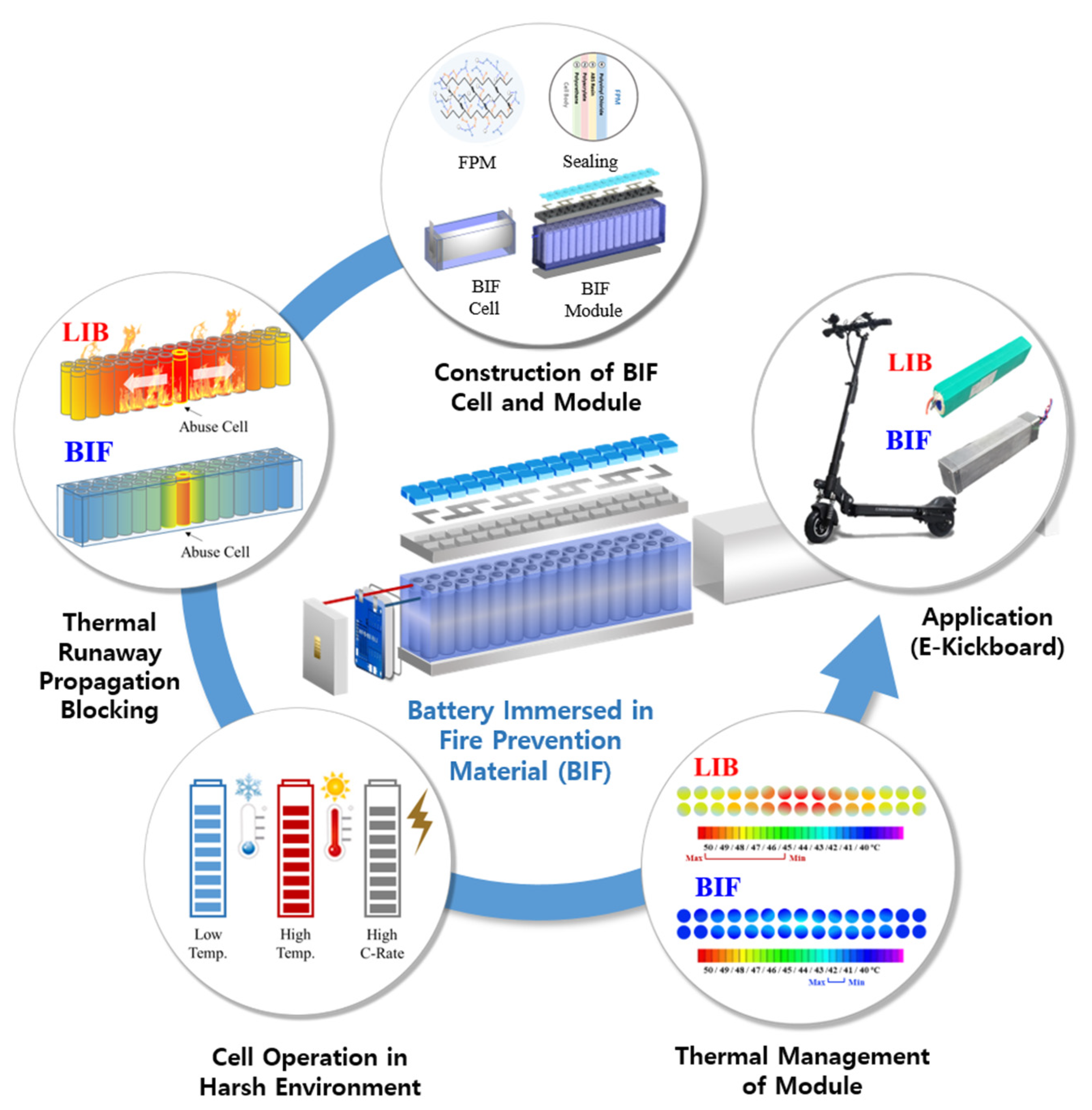
Figure 1. Configuration of the battery immersed in fire prevention material (BIF) and research from the construction of the battery to application in sequence.
Energies 17 02418 g001
Figure 2. Functional components of BIF: (a) structure and composition of fire prevention material (FPM) immersing the battery, and the application of (b) sealing within the cell body and cell tabs to prevent direct contact of FPM to the battery.
Energies 17 02418 g002
Figure 3. Overview of the (a) BIF cell and (b) BIF module with their components and structure.
Energies 17 02418 g003
Figure 4. Setup and preparation for the abuse test (overheating) of the BIF module.
Energies 17 02418 g004
Figure 5. Configuration of the mechanisms comparison of the LIB and BIF with heat transmission sequence and the direction of the heat distributions during (a) thermal management under normal operating conditions and (b) thermal runaway propagation under abusive conditions.
Energies 17 02418 g005
Figure 6. (a) Configuration of temperatures and voltage of the LIB module while abusing the target cell; (b) draft of the LIB module with an overheated single cell at the maximum temperature during the test, temperatures by location, and module after the test; (c) configuration of temperatures and voltages of the BIF module while abusing the target cell; (d) draft of the BIF module with an overheated single cell at the maximum temperature during the test, temperatures by location, and module after the test.
Energies 17 02418 g006
Figure 7. Heat management capability of BIF cell against LIB cell in harsh operating conditions (high C-rate and temperature): (a) temperature tendency of LIB cell and BIF cell by cycle, (b) enlargement, (c) charge and discharge voltage of the LIB cell and BIF cell, and (d) capacity comparison by cycle number.
Energies 17 02418 g007
Figure 8. (a,b) Electrochemical impedance spectroscopy (EIS) comparison of LIB cell and BIF cell by cycle in Nyquist plot. (c,d) EIS comparison of LIB cell and BIF cell by cycle in Bodet plot. (e) Rct (2nd semicircle) impedance fitting data of LIB cell and BIF cell by the cycle number. (f) Equivalent circuit of battery for data fitting, active area of battery, and impedance measuring conditions.
Energies 17 02418 g008
Figure 9. Performance (voltage efficiency, temperature) comparisons by gradual discharge C-rate increases in (a) LIB cells and (b) BIF cells using pulse test.
Energies 17 02418 g009
Figure 10. Temperature of the module by spots and their configuration while cycling; (a) LIB module, (b) BIF module, (c) and temperature comparisons of the module by time and spots, grey lines indicate charge and discharge cycle.
Energies 17 02418 g010
Figure 11. (a) Setup configuration of e-kickboard with LIB and BIF modules; (b) temperature measuring spots of the module; (c) temperature of LIB and BIF module by spots during kickboard operation and rest.
Energies 17 02418 g011
Table 1. Specification of the BIF Cell.
ParametersDescription
BatteryCellLIB 18650 type
Cell ManufacturerSamsung
Cell Model INR18650-30Q
Nominal Voltage3.7 V
Maximum Voltage4.2 V
Capacity3 Ah
Energy11 Wh
ChargeMaximum
Charge Voltage
4.2 V
Continuous
Charging Current
1.5 A
DischargeMaximum
Discharge Voltage
3.0 V
Continuous
Discharge Current
1.5 A
OthersDimension (B × W × H)26 mm × 79 mm × 26 mm
Total Weight (FPM Weight)58.5 g (FPM: 16.4 g)
Operating Temperature−10–40 °C
Table 2. Specification of the BIF Module.
ParametersDescription
BatteryCellLIB 18650 type (10s3p)
Cell ManufacturerSamsung
Cell Model INR18650-30Q
Nominal Voltage37 V
Maximum Voltage42 V
Capacity9 Ah
Energy333 Wh
ChargeMaximum
Charge Voltage
42 V
Continuous
Charging Current
4.5 A
DischargeMaximum
Discharge Voltage
30 V
Continuous
Discharge Current
4.5 A
OthersDimension (B × W × H)45 mm × 350 mm × 80 mm
Total Weight (FPM Weight)2.8 kg (FPM: 492 g)
Operating Temperature−10–40 °C
Battery
Management
System
FunctionOver-discharge, Overcharge,
Over-current, Balance, etc.
Table 3. Step Time Intervals, Abrupt Temperature Rises, and Propagated Cell Amount while Thermal Runaway Occurs in LIB and BIF Module.
Thermal Runaway
LIBStep Time (s)3771344630
△T ( )152.9163.1741.1900.3
Propagated Cell Amount1 ea (Abuse)1 ea5 ea6 ea
BIFStep Time (s)396129--
△T ( )110.0113.1--
Propagated Cell Amount1 ea (Abuse)1 ea--
Table 4. Increases in Rct (2nd Semicircle) impedance of LIB cell and BIF cell by cycle.
Rct (2nd Semicircle)0 Cycles14 Cycles28 Cycles42 Cycles
LIB (Ω)0.027910.031380.038380.05305
BIF (Ω)0.025970.026340.031740.03250
Table 5. Maximum Temperatures (End of Discharge in each Cycle) of LIB Cells and BIF Cells in Pulse Test.
Temperature (°C)1C2C3C4C5C6C
LIB Cell47.247.761.461.975.675.890.991.1105.1---
LIB Case41.641.744.244.347.947.950.850.952.6---
BIF Cell42.542.649.149.257.357.465.365.477.677.787.887.9
BIF Case40.340.340.540.540.940.941.341.441.841.842.142.2
Disclaimer/Publisher’s Note: The statements, opinions and data contained in all publications are solely those of the individual author(s) and contributor(s) and not of MDPI and/or the editor(s). MDPI and/or the editor(s) disclaim responsibility for any injury to people or property resulting from any ideas, methods, instructions or products referred to in the content.