1. Introduction
Synchronous reluctance motors, due to their low production cost and only slightly lower functional parameters compared to permanent magnet synchronous machines (PMSMs), are generating more interest as an effective alternative to PMSMs in electric vehicle propulsion systems [
1,
2]. The electromagnetic torque in the SynRMs results from magnetic asymmetry in the rotor obtained by introducing air barriers to the magnetic flux excited by the stator winding [
3]. The magnetic flux barriers are cut out in the rotor sheets so that the remaining ferromagnetic material creates a path for magnetic flux along the direct axis of the machine [
4]. The lack of permanent magnets in the magnetic circuit of the SynRM significantly reduces the cost of the machines [
5,
6,
7]. The lack of permanent magnets increases the reliability of the machine in the context of operation in fault conditions by eliminating the risk of irreversible partial demagnetization associated with permanent magnet synchronous motors [
8,
9].
A significant increase in interest in SynRM machines has been observed in recent years. Due to the strong influence of saturation and the effect of punching on the magnetic properties of metal sheets, field methods combined with optimization algorithms are increasingly used to design the magnetic circuits of these machines [
10,
11,
12]. Optimization procedures are employed to provide the optimal shape of the flux barriers in the rotor and geometry of the stator, taking into account mechanical constraints, technological feasibility, and the discussed impact of mechanical stresses on the magnetic properties of the rotor core [
12].
On the other hand, with a fixed motor structure (i.e., rotor and stator laminations), the improvement of the functional parameters of the SynRM is possible only by modification of the winding of the machine. This paper discusses how to implement multi-phase systems to improve the performance of the SynRM with a given geometry of its magnetic circuit. As for PMSMs, it has been demonstrated, among other things, in [
13,
14] that the multi-phase machines are characterized by much lower electromagnetic torque ripples than in the case of a three-phase supply. In addition, it is reported that more phases allow the electromagnetic torque to be increased at approximately the same thermal load of the machine. Another important advantage of multi-phase machines, especially their application in electric vehicle powertrain systems, is high reliability resulting from redundancy in the power supply system [
15,
16,
17,
18,
19,
20]. It has been shown in [
21] that in the event of a failure of one of the DC-to-AC three-phase component inverters that form the multi-phase supply system, the drive can continue to operate effectively [
21]. The main goal of the conducted research is to evaluate whether the abovementioned advantages of multi-phase PMSMs are valid regarding SynRMs. To answer this question, a synthesis of the six-phase winding of the SynRM was carried out. Then, a comparative analysis of electromagnetic performance between the developed six-phase SynRM and the reference three-phase SynRM designs was carried out.
This paper is organized as follows: First, the synthesis of the six-phase winding is reported and the type of coil connection to this winding is discussed. Next, in
Section 3, the extended Clarke and Park transformations used in the vector control and the finite element analysis of the six-phase SynRM are described. A finite element method (FEM) analysis of the six-phase SynRM performed to verify the winding design and compare the performance of three-phase and six-phase motors is described in
Section 4. The conducted analyses also include studies on the performance of the considered machines under fault conditions of one of the three-phase inverters forming the supply system. The results of preliminary tests carried out on the six-phase SynRM prototype as well as conclusions regarding the conducted research are provided in the last two sections of this paper. The major parameters of the case study machine are summarized in
Table 1.
2. Synthesis of the Six-Phase Winding
In order to develop a six-phase winding adapted to the objectives assumed at the conceptual stage, it was necessary to analyze the design parameters of the stator. The stator of the reference three-phase SynRM has 36 slots and a single layer of a three-phase winding, exciting a four-pole rotating magnetic field. Due to the rotor structure of the reference design, the six-phase winding under consideration has to generate a four-pole rotating magnetic field. The first step in the synthesis of the AC electric machine winding is to determine the number of slots per pole and phase
q. This will allow one to determine the starting point for further selection of the type of winding [
22]. The number of slots per pole and phase
q is calculated using the following classical formula:
where
is the number of slots,
is the number of pole pairs, and
is the number of phases.
The fractional value of
q (=3/2) for
m = 6 determines the need to use a two-layer fractional-slot winding and correct the arrangement of the coil sides in the machine slots. For this purpose, the classical approach based on analysis of voltages induced in the coil sides in the slots was carried out. In an analysis limited to the fundamental harmonic, the rotating magnetic field in the system induces a voltage in the coil sides placed in the stator slots. The vectors of the induced voltages are shifted in phase by the angle resulting from the sequence of the coil sides distribution along stator slots. For the given rotational speed of the rotor, each coil side is affected by the equivalent of a full turn of the magnetic field per pole. Thus, the phase angle α between the voltages induced in adjacent coils directly depends on the number of slots as well as on the number of pole pairs and can be expressed as
where
is the phase angle between the induced voltages on adjacent coil sides.
As a result, one can determine a voltage star in which the vectors are shifted by the angle α. The number of vectors equals
S/
p because each pole pair creates the same distribution of the vectors; thus,
where
is the number of vectors of a voltage star.
Therefore, only one pair of poles is considered since the remaining pole pairs give the same results. This significantly increases the transparency of the analyzed case.
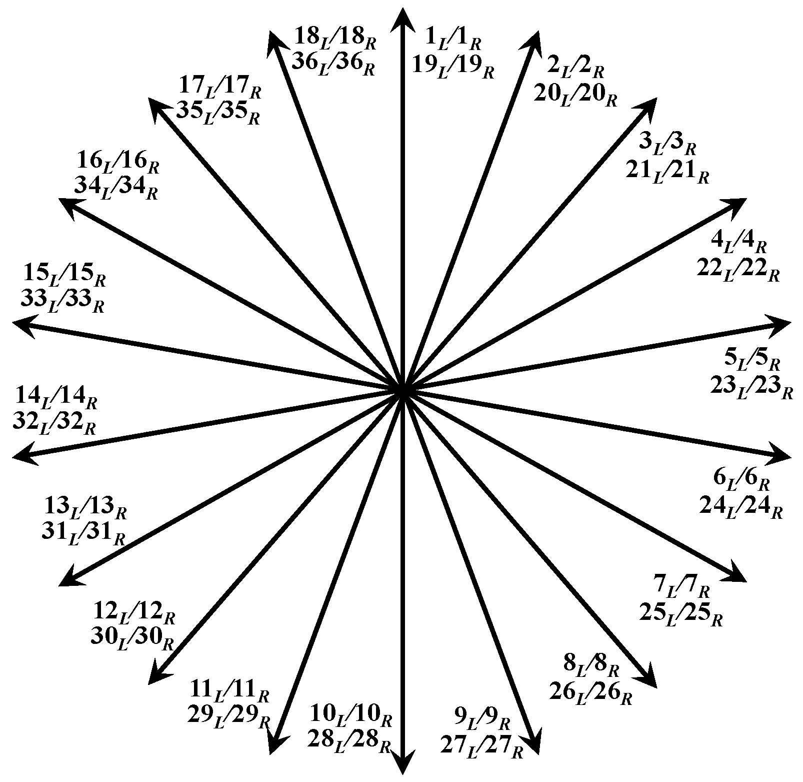
The voltage star for the tested motor is presented below.
The voltage star determined in this way takes into account the numbering of individual coil sides. Each vector corresponds to a slot containing two coil sides. The sides of the coils are distinguished as right (
R) and left (
L) and are assigned numerically to the slots in which they are located. A description of the order of the slots is presented in the winding schemes shown in figures below. The resultant voltages induced in individual coils can be determined based on the vectors. The six-phase system is obtained by providing properly arranged coils to phase windings. As mentioned above, the voltage star is related to one pair of poles of the machine; however, in order to organize and represent the identity of the voltages induced in the coils assigned to the second pair of poles, they are expressed in
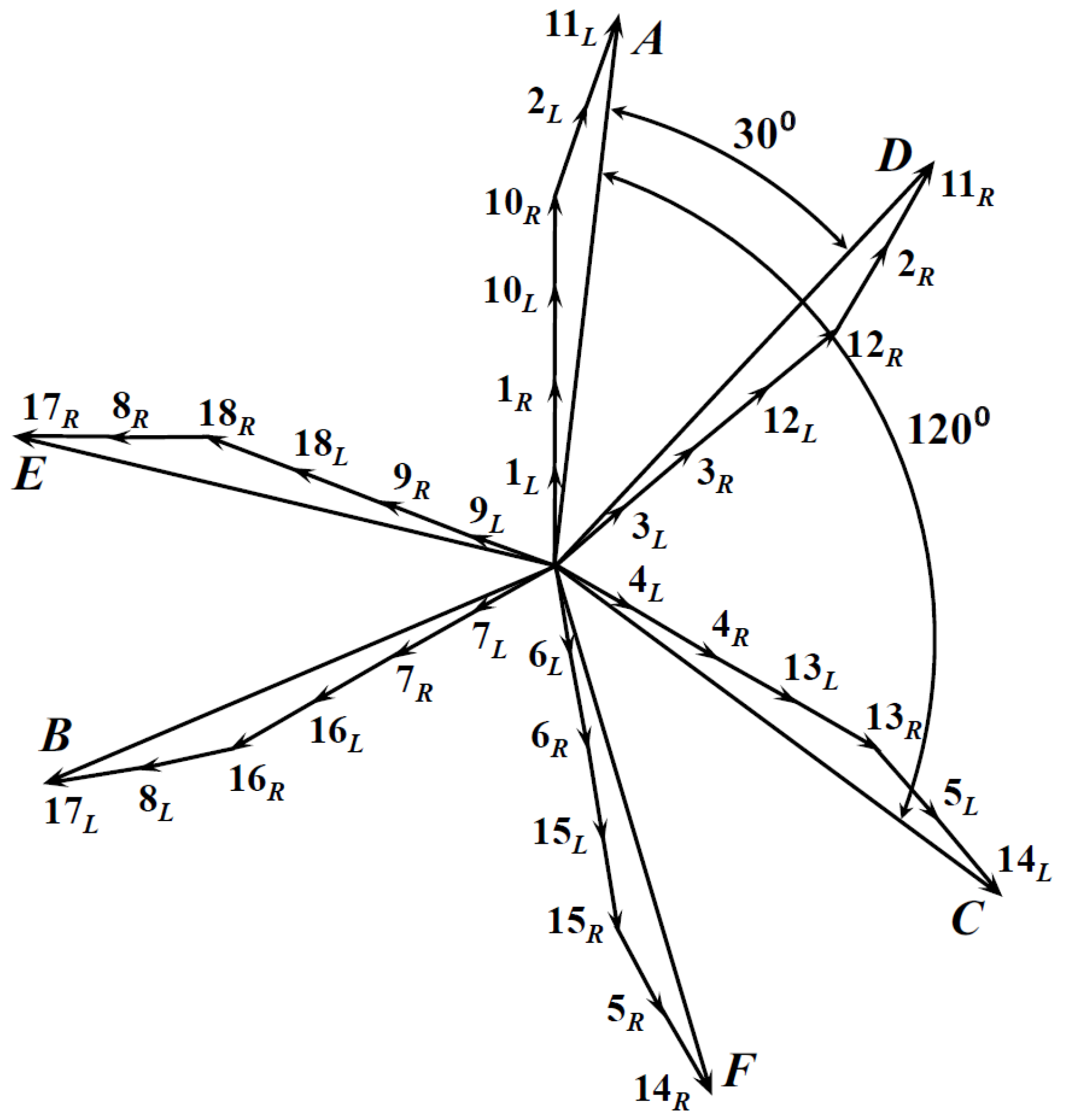
Figure 1 by numbers of slots higher than 18. It should also be mentioned that the phase diagram illustrating an arrangement of coils in the phase windings shown in
Figure 2 relates to one pair of poles in which each phase vector is a sum of 6 vectors, corresponding to the six sides of the coils connected in series. The corresponding voltages induced over the second pole pair can be connected in parallel or in series, depending on the applied scheme. For the scheme considering the series connection, vectors of the voltages induced over the first and second pair of poles would be connected in series; therefore, each phase will be a sum of 12 vectors.
According to the winding diagram, there is an angular displacement of 40° between vectors 1L and 3L. Vectors 1L, 1R, 10L, and 10R belong to the “main” slots of phase A (i.e., slots that contain only coil sides assigned to the given phase). Vectors 2L and 11L lie in an adjacent “common” slot, i.e., where there are coils with two different phases, and where, according to Formula (3), the induced voltage is shifted by 20° with respect to the main slot voltage. The phase shift of vectors 2L and 11L is oriented CW (clockwise) according to the transition from the first to the second slot. An analogous situation occurs in phase D; however, the vectors of the induced voltages in an adjacent slot are oriented CCW (counterclockwise) as the transition takes place from the third to the second slot. The geometry shows that the obtuse angle between vectors 10R and 2L is 160°. The upper angle of the triangle obtained from the voltage vectors of phase A has an angle of 15°, so the angle at the base of the star is 5°. It follows that the main vectors of phases A and D are shifted in relation to the value of the main slot by 5°. To summarize, if subtracting from the initial angular displacement by 40° and 5° on both sides, we obtain 30° shifts between the resultant vectors of phases A and D. Successive pairs of phases are constructed analogously to this description. Although the C phase in the winding diagram is shifted by 60° relative to the A phase, it has a negative value. This means that it must be moved counterclockwise. If we want to convert phase C to positive values, we invert it by 180°. Then, the shift of phase C with respect to phase A is 120°. We perform the same operation for phase F.
The fractional value of
q determines the need to use a two-layer fractional-slot winding, which enables the effective and correct arrangement of the side coils in the machine slots according to the voltage star shown in
Figure 2. The resultant arrangement of the sides of the coils under a single pole is shown in
Figure 3.
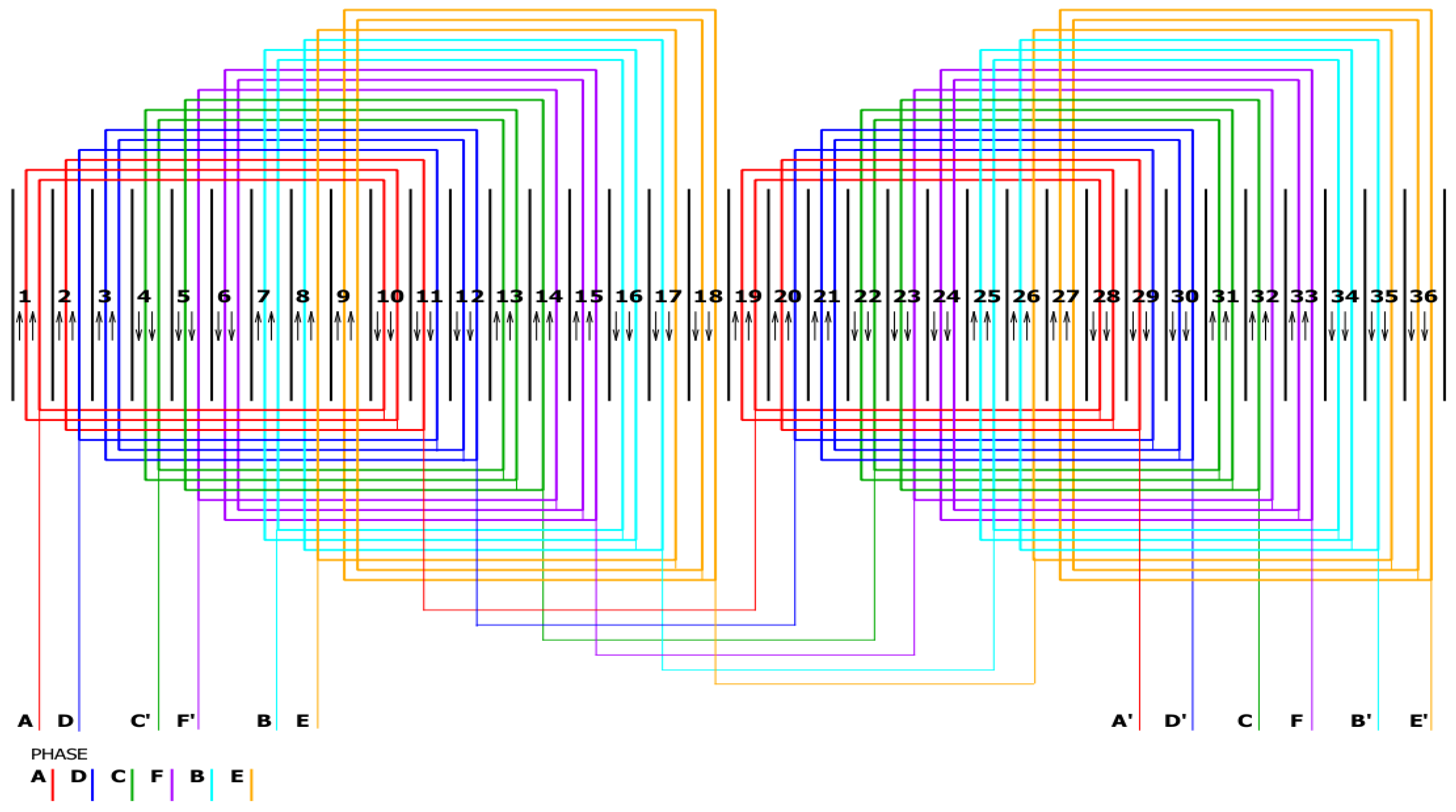
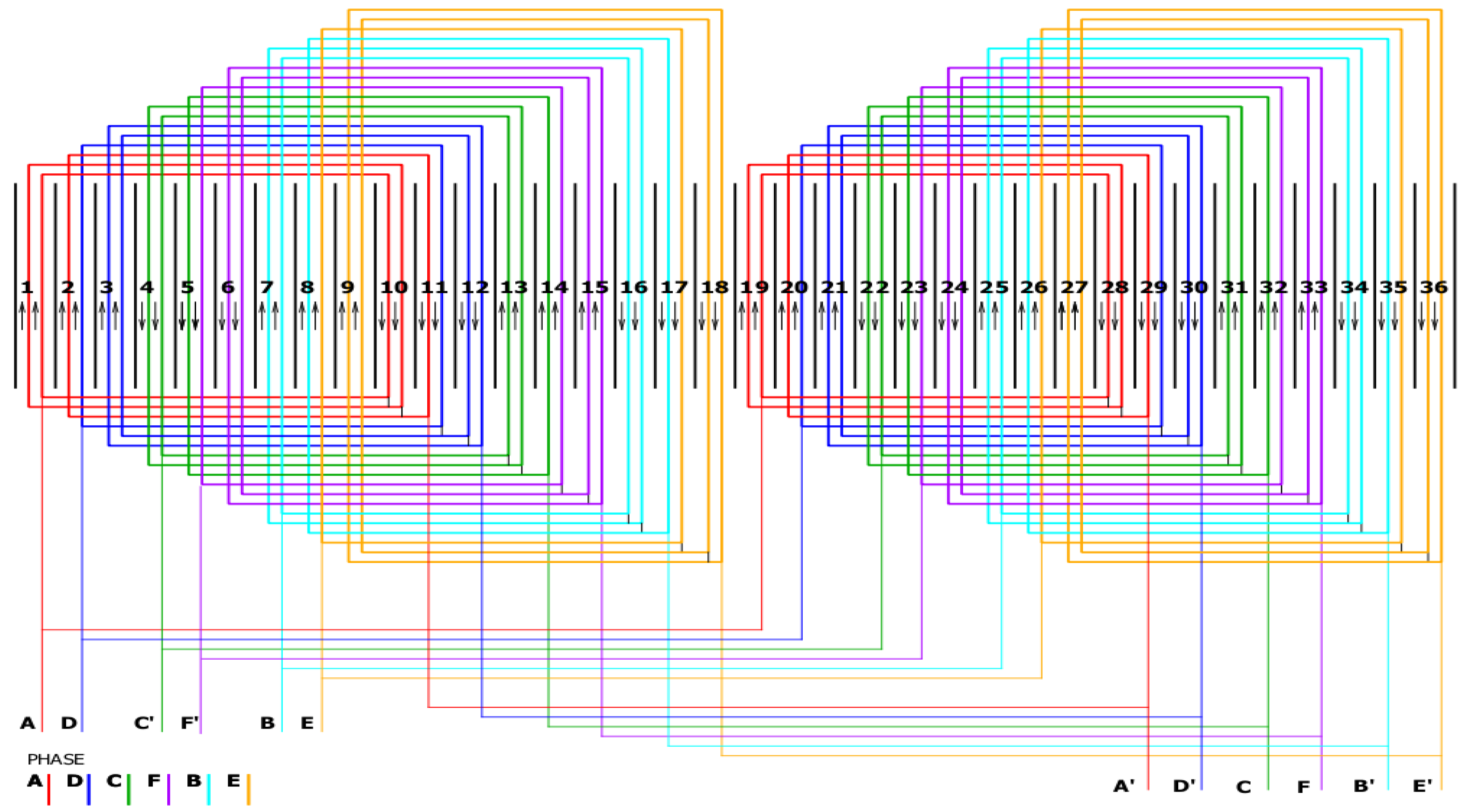
Based on the above winding design calculations, a diagram of a six-phase winding was determined. Taking into account the various possibilities of connecting groups of phase coils, two versions have been proposed: serial (
Figure 4) and series-parallel (
Figure 5) [
23].
The type of coil connections corresponding to the pair of poles of the machine allows one to adjust the voltage to the adopted requirements resulting from, for instance, limited voltage in the energy storage of the electric vehicle. In the six-phase SynRM under consideration, the series-parallel connection of coil groups for a six-phase winding was used.
3. Extended Clarke and Park Transformations
Synchronous reluctance machines, like all classical synchronous machines, are characterized by a lack of starting torque. In practice, in order to apply these machines in variable-speed drives, it is necessary to use a frequency converter with a control system that allows one to control the values of phase currents depending on the position of the rotor in the machine. In the case of SynRMs, similarly to PMSMs, field-oriented control (FOC) algorithms are commonly used for this purpose. However, in the case of multi-phase systems, in order to implement FOC, it is necessary to extend the Clarke transformation to determine phase currents on the basis of
currents in the stationary αβ system. When transforming systems other than three-phase, it is necessary to verify and modify the matrix transforming the stationary
m-phase natural system into stationary αβ vectors [
24,
25]. In this case, assumptions such as the symmetry of the
m-phase system, the star connection of the winding, or the selection of the interfacial angle of 2π/
m, should be taken into account. The extended Clarke transformation for multi-phase systems is represented by the matrices below.
where
where i
αβ represents the currents in the αβ reference frame and i
ABC…m represents the currents of the natural system.
The factor 2/m included in Equation (4) allows for the preservation of amplitude during the application of the Clarke transformation. It can be noted that such formulation leads to the lack of balance in terms of power in the different reference frames. Nevertheless, since power balance is not required for control system effectiveness, the amplitude-invariant form of the Clarke transformation has been adopted in further studies of six-phase SynRM performance.
From the above equations, it can be concluded that each subsequent phase is nothing more than an additional vector shifted by the angle resulting from the total number of phases. The phase angle between the vectors of the individual phases is defined by the winding. One can see that the winding considered in this paper forms an asymmetric six-phase system [
22,
25]. For such an arrangement, the phase angle between two three-phase systems, ABC and DEF, is as follows:
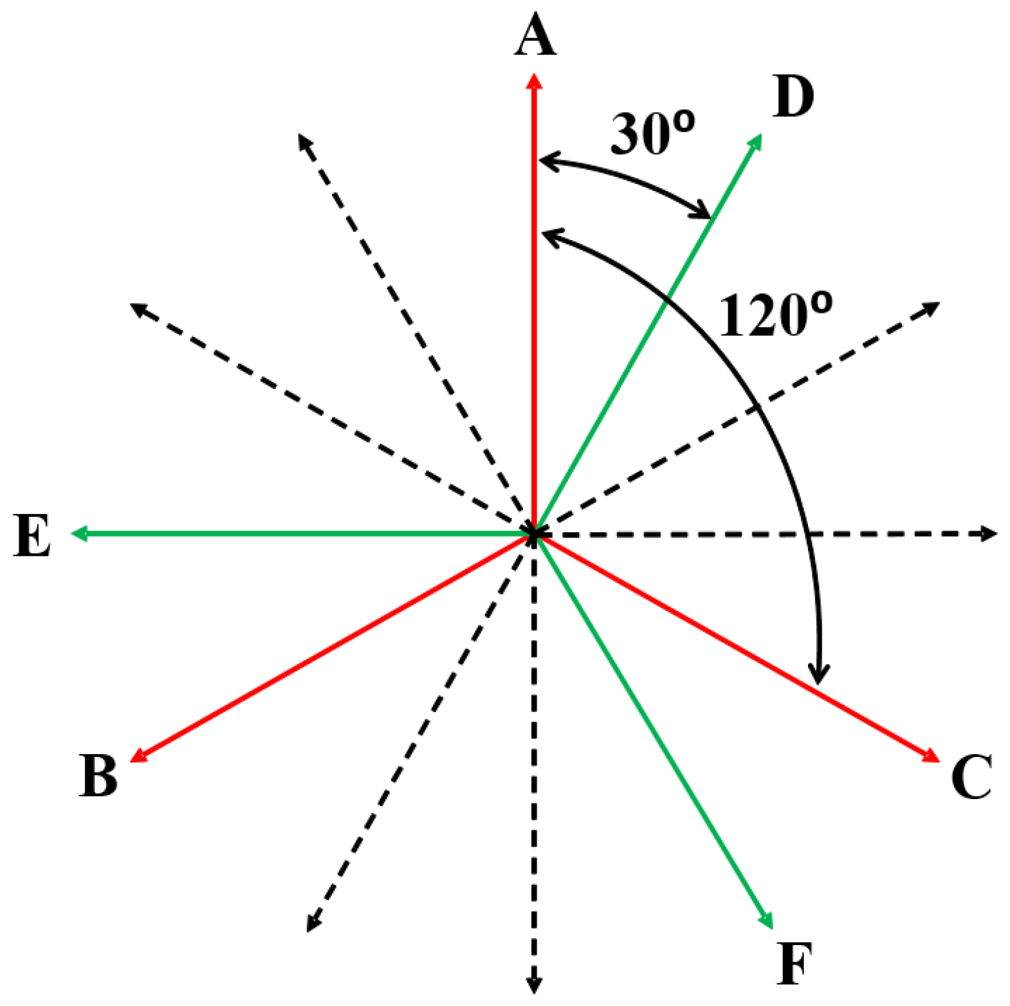
This means that two independent three-phase systems shifted in phase between each other by 30° to form a resultant six-phase system [
22,
25]. The
Figure 6 shows a graphic interpretation of an asymmetric six-phase system [
22].
Taking into account the arrangement of the phase vectors discussed above, shown in an asymmetric six-phase system, the modified Clarke forward and reverse transformations can be expressed as follows:
where
Next, according to the standard FOC algorithm, the Park transformation of
quantities to the orthogonal direct
d and quadrature
q rotary reference frame is applied. Assuming the alignment of the
d and α axes, the Park transformations can be expressed as follows:
where θ is the angle position of the rotor, and
To confirm the correctness of the transformations presented above, a block diagram model was implemented in the Matlab Simulink (R2023b) environment. This model was then used to verify the correctness of the transformation matrices by analysis of the waveforms of transformed quantities. The block diagram models representing forward and reverse transformations are shown in
Figure 7 and
Figure 8, respectively.
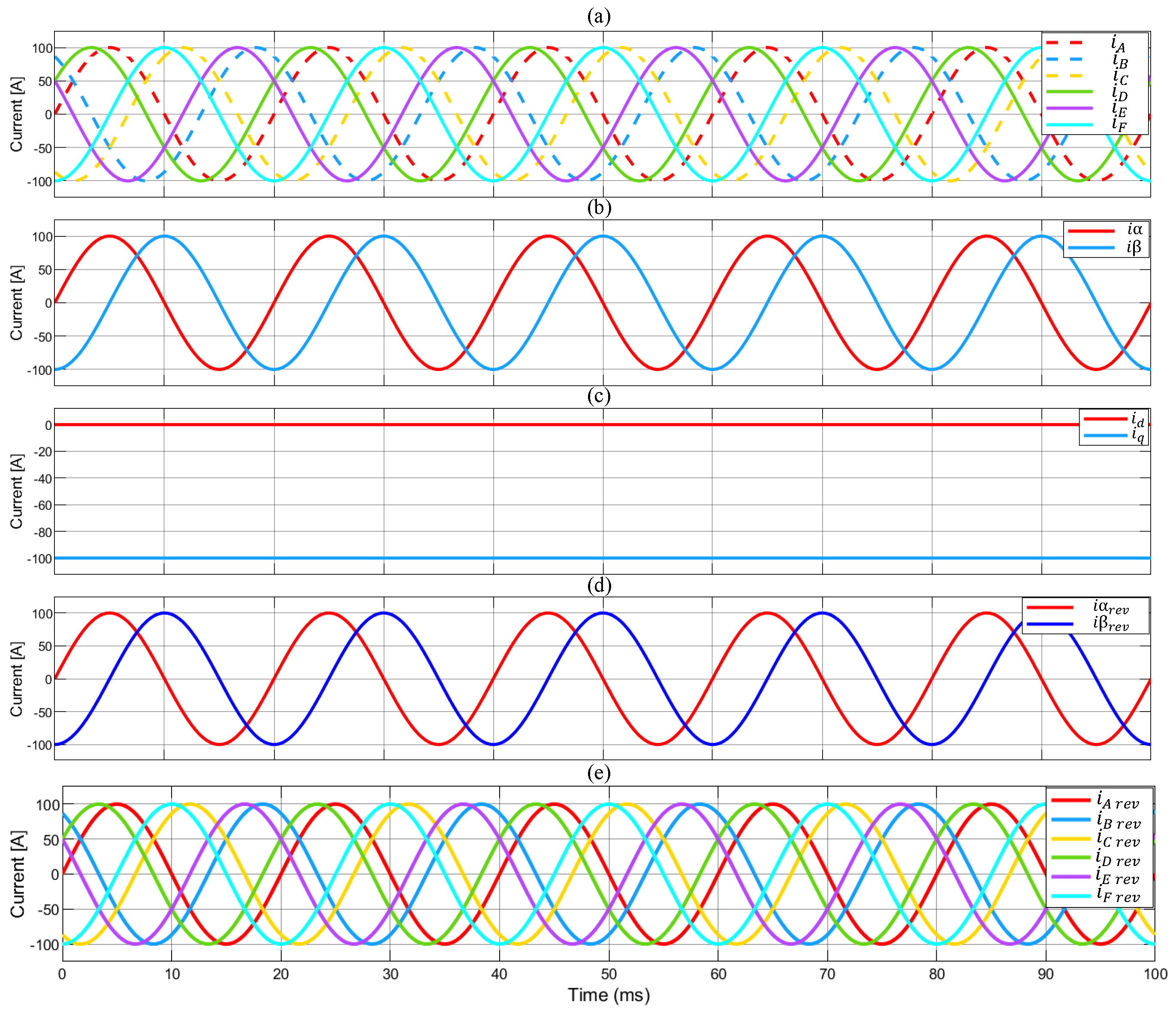
The waveforms representing quantities for individual transformations were determined using the developed Simulink model. The analysis of the results confirms the correctness of the performed operations. In
Figure 9b, representing the result of the Clarke transform, two sinusoids that shifted relative to each other by 90° were obtained, according to the assumptions of the transformation.
Figure 9c shows the result of the Park transformation, depicting two constant reference values that occurred due to the synchronous rotation of the reference system of vectors
d and
q together with the rotor of the machine, which causes these vectors to remain unchanged in time. For reverse transformations, expectedly, the model returned identical waveforms like the input in the natural system for forward transformations—see
Figure 9d,e.
4. Results of Finite Element Analysis
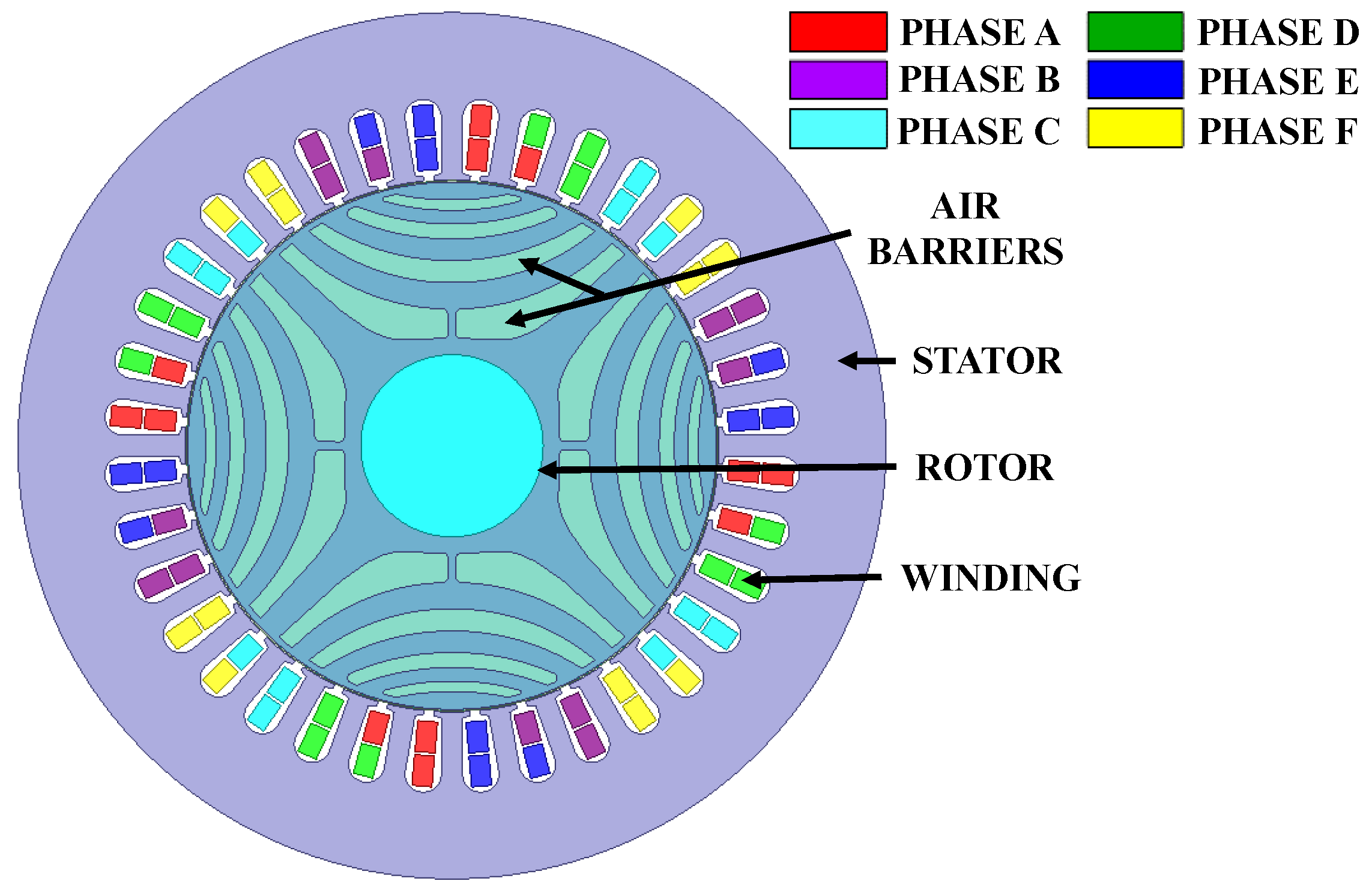
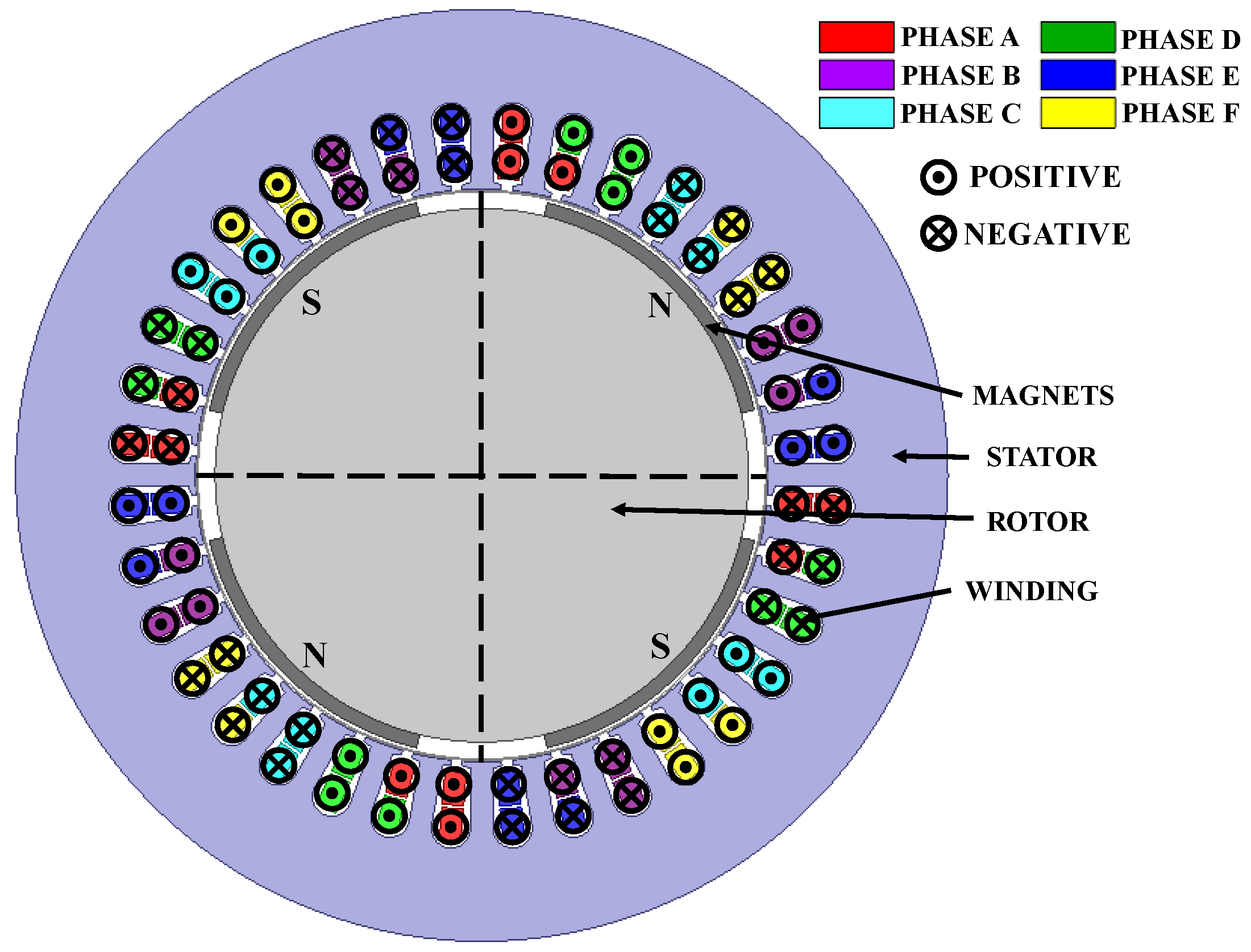
In order to study the performance of the considered SynRM, a numerical model employing the finite element method (FEM) to determine the magnetic field distribution and calculate electromagnetic torque and forces was developed. The planar symmetry of the magnetic field distribution has been assumed at the current stage of the research. The geometry of the developed model with an assignment of the coils to the phase windings is shown in
Figure 10.
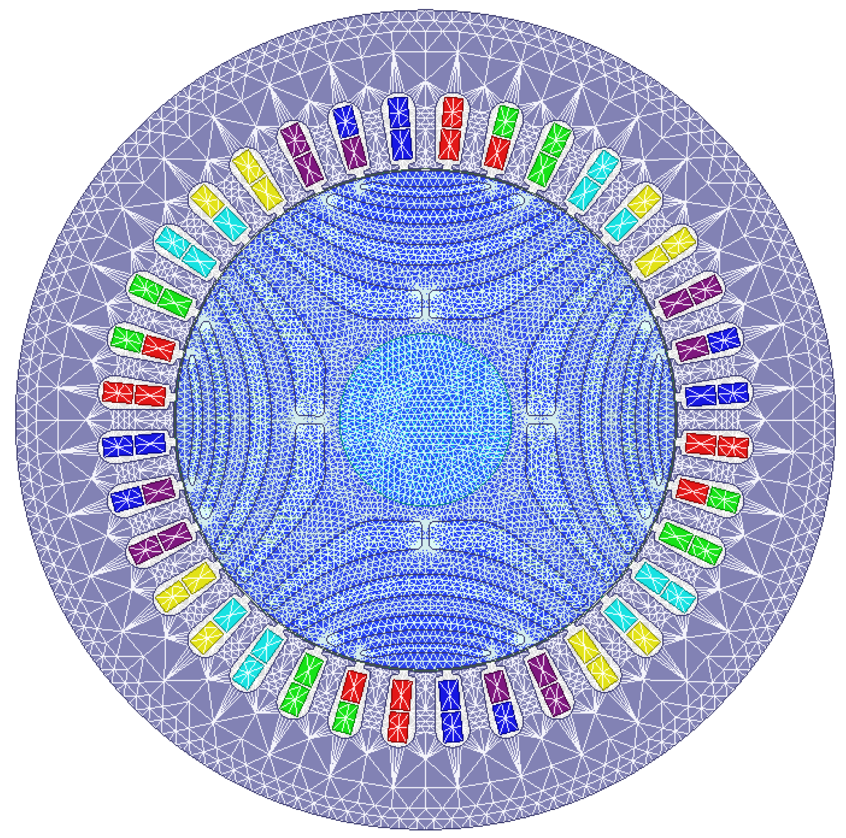
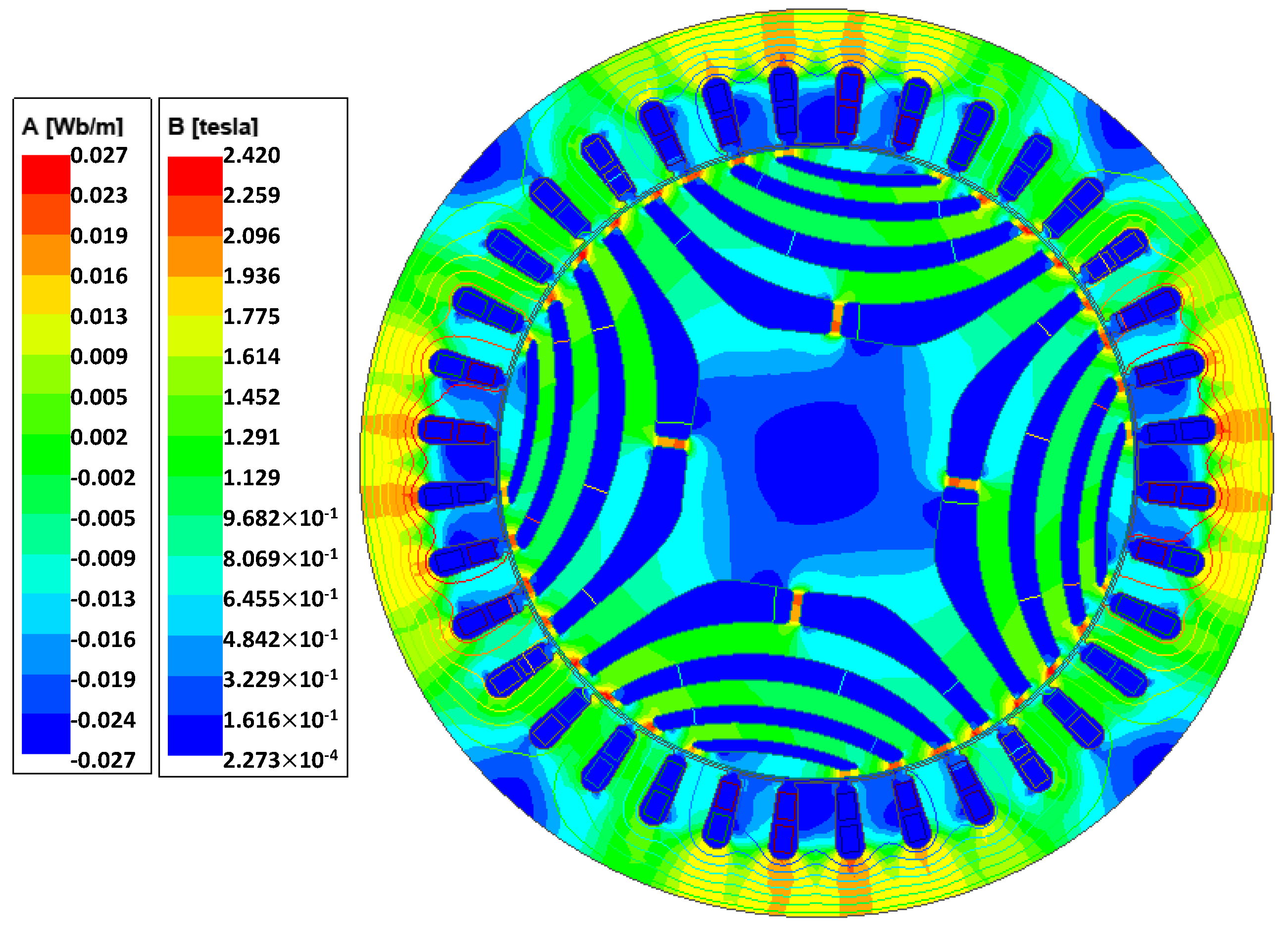
According to the FEM, in order to determine the distribution of the magnetic field and, on its basis, define integral parameters such as torque and forces acting on the rotor of the machine, the machine’s geometry is discretized. To determine currents in the winding of the machine, the transformations discussed in
Section 3 were used. A view of the discretizing grid used in the calculations and an exemplary magnetic flux density distribution in the considered system for rated load conditions are shown in
Figure 11 and
Figure 12, respectively.
The finite element mesh applied to the developed model of the SynRM consists of about 24,000 triangular elements.
The correctness of the designed winding can be proven by means of analysis of induced voltages. In the case of the SynRM, determining induced voltages by the FEM is more challenging than for the PMSM because there is no magnetic flux in the SynRM in the absence of current in the winding. Therefore, in such a state, no electromotive force (EMF) will be induced. Of course, like for normal operation of the SynRM, the magnetic flux can be excited by forcing the current in the direct axis of the machine. Nevertheless, if the winding is not properly designed, it can lead to unreliable results of EMF calculation. Therefore, for testing purposes in the proposed approach, an additional numerical model of a motor with the proposed six-phase winding and four-pole permanent magnet rotor was developed and used to determine the EMF waveforms. The geometry of the developed model is shown in
Figure 13.
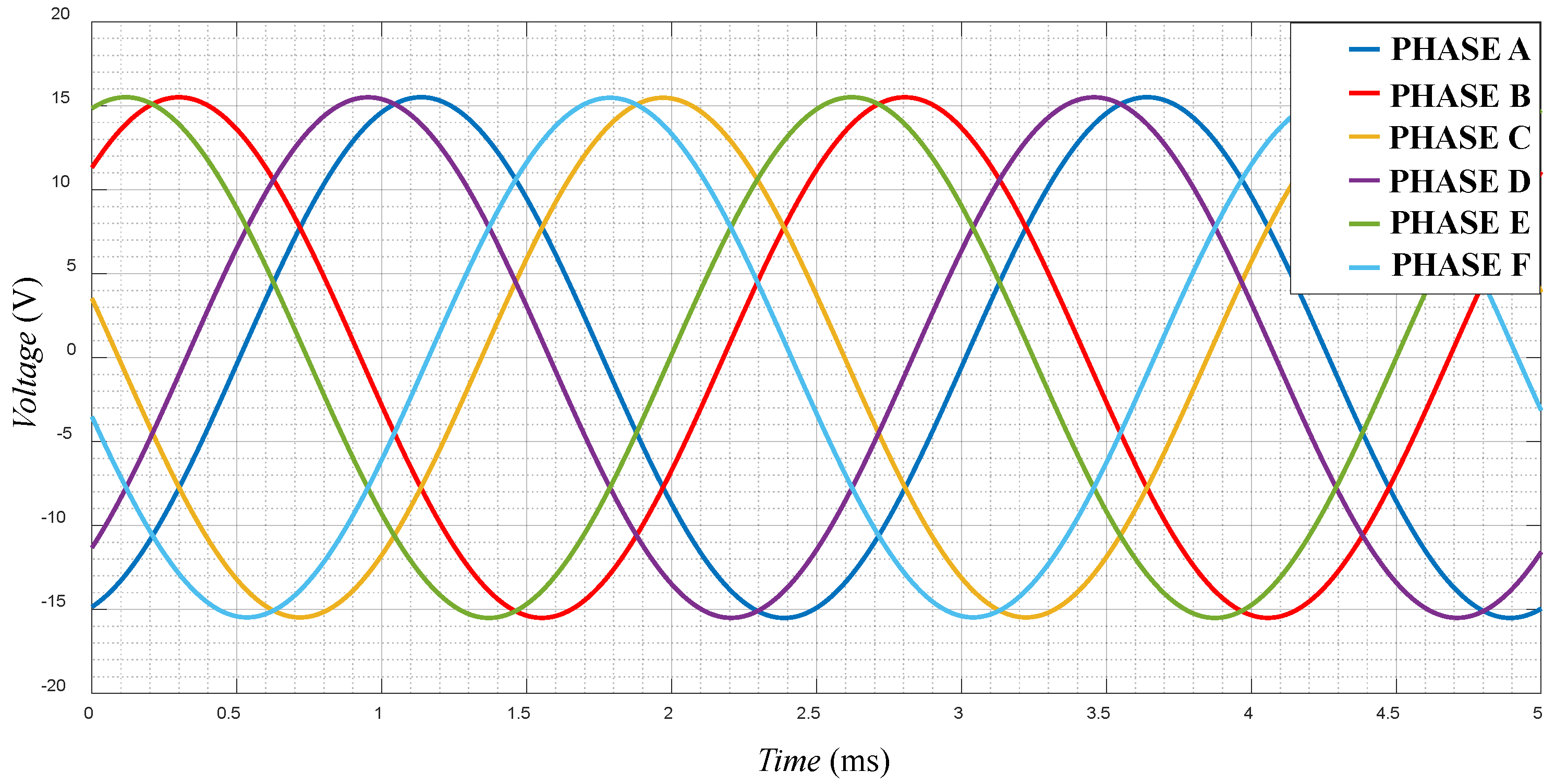
The determined waveforms of the phase back electromotive force are shown in
Figure 14. It can be seen that the frequency of the obtained EMF is equal to 400 Hz, which corresponds to a rotor speed of 12,000 rpm applied in the model.
The obtained waveforms of the induced voltages form a six-phase system, and the phase shifts of the respective voltages agree with the phase shifts predicted at the stage of winding synthesis and voltage star analysis.
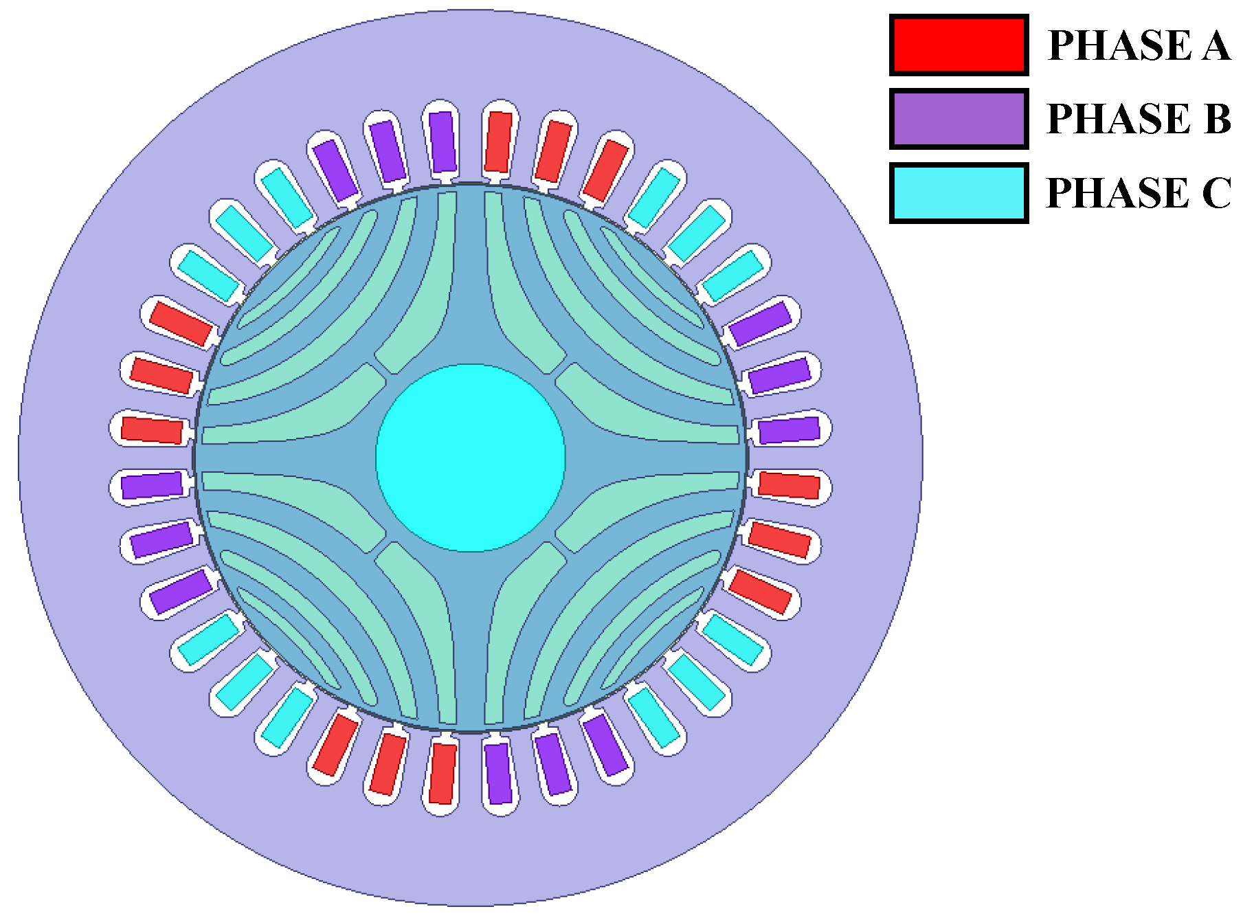
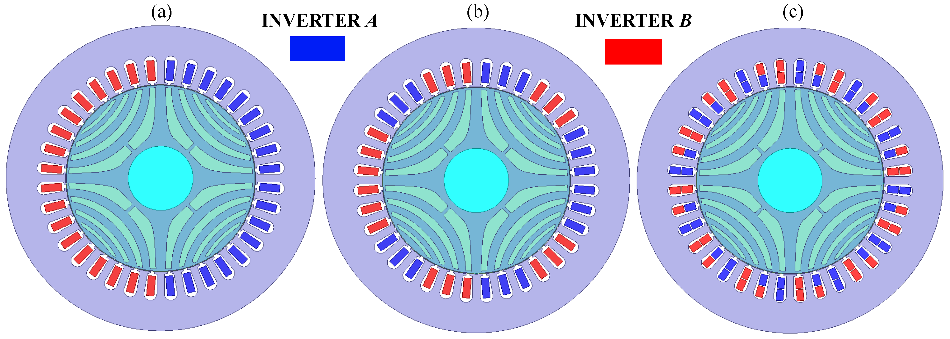
After confirming the correctness of the six-phase winding, the comparative analysis of the performance of the reference three-phase and six-phase SynRMs under inverter-fault conditions was carried out. In the case of the three-phase machine, it has been assumed that the power supply system consists of two jointly controlled three-phase inverters connected to the machine winding. For this purpose, it was necessary to split the three-phase winding so that it would be possible to power the machine from two inverters. The arrangement of the three-phase winding of the reference machine with 36 slots and 4 poles is shown in
Figure 15.
It can be noted that there are two possible ways of connecting the three-phase winding to a two-inverter system (see
Figure 16a,b, respectively) and one way for a six-phase winding (
Figure 16c). The schematic assignment of the coils to individual inverters in the considered connection methods is shown in
Figure 16.
In the first stage, the electromagnetic torque waveforms were analyzed for the considered configurations of the power supply system of three- and six-phase SynRMs. For ease of description, configuration (a) will be referred to as
C1, (b) as
C2, and (c) as
C3, corresponding to power system configurations shown in
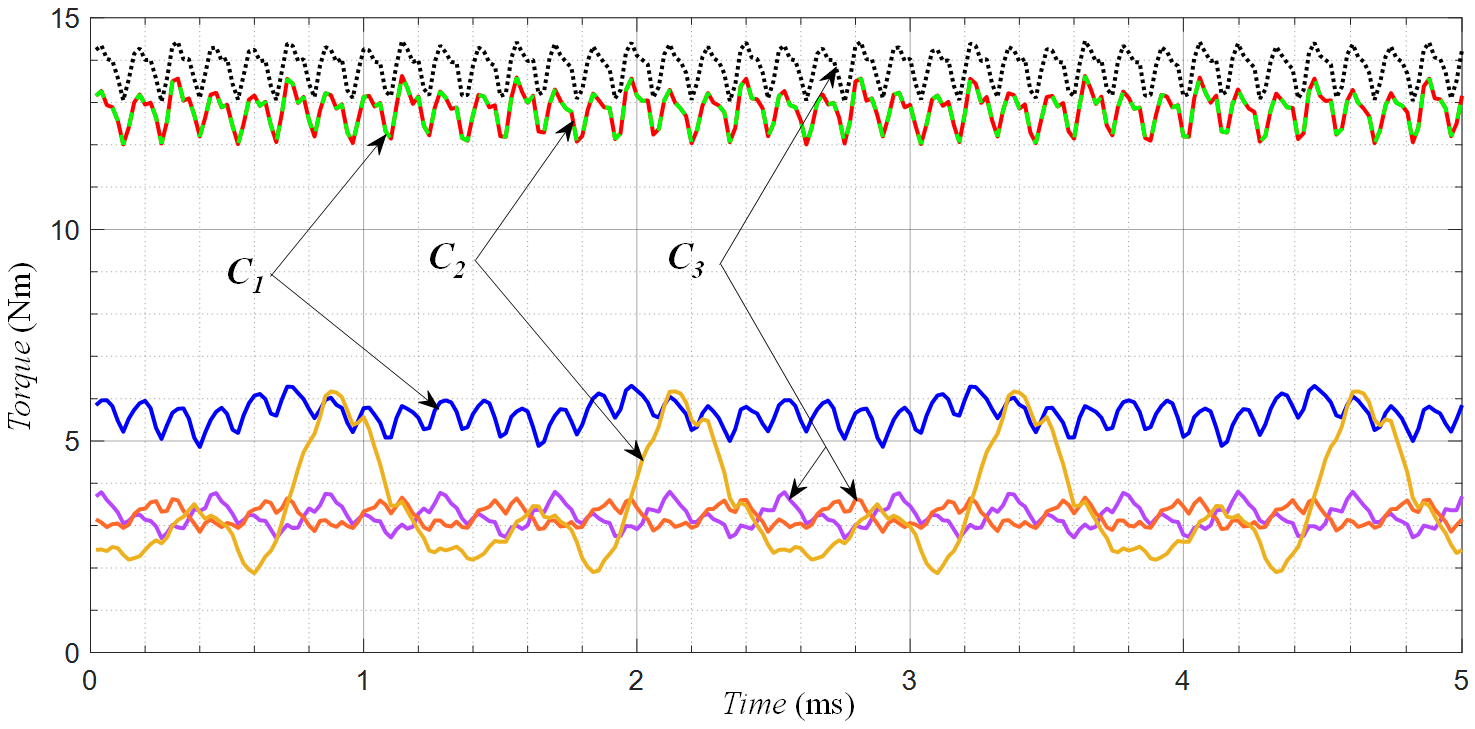
Figure 16a–c, respectively. The calculated electromagnetic torque waveforms are shown in
Figure 17. The dashed lines correspond to the torque waveforms determined in the state of proper operation of the power supply system (defined when the power system operates properly), while the continuous lines correspond to the fault-condition state in which one of the inverters is disconnected from the machine (the output currents are equal to zero in all three phases of one inverter).
Studying the obtained results, it can be concluded that considering the proper operation of the A and B inverters, the machine powered by configuration C1 obviously generates the same torque as the machine powered by configuration C2. However, in the event of failure of one of the inverters, the torque generated by the motor powered by the C1 configuration drops by half compared to the value of the torque generated under normal operation conditions. It should be highlighted that electromagnetic torque ripple slightly increases (to about 25%), allowing for further operation of the machine with the limited value of output torque. The second configuration of the three-phase SynRM supply, C2, shows that the inverter-fault condition prevents further operation of the machine due to extremely large torque ripples.
Considering the six-phase SynRM supplied according to the
C3 configuration of the supply system, it can be observed that under normal operation conditions, the electromagnetic torque is about 7% higher than in the case of the three-phase machine. Looking at the torque ripple level (10.4% for the six-phase and 12.6% for the three-phase machine), no significant reduction can be seen. By studying the operation of the six-phase SynRM under inverter-fault conditions, it can be observed that with the proper operation of both inverters, the torque value drops to 30% of the nominal value. The phase shifts of the torque waveforms related to
C3 under fault conditions (pink and orange curves in
Figure 17) result from the phase shifts between ABC and DEF three-phase systems in an asymmetric six-phase system.
It should be noted that the assessment of the quality of machine operation under fault conditions should not be limited to the analysis of the electromagnetic torque value and ripples. During the normal operation of the electrical machine, beside tangential forces contributing to the electromagnetic torque (as integral of the tangential component of the Maxwell stress tensor over the air-gap circumference), the radial forces are present and have an impact on, among other things, magnetically exited noise and vibrations. In the ideal case, i.e., assuming no eccentricity of the air gap and symmetry of the winding, these radial forces are balanced and the resultant global force acting on the whole rotor is close to zero. The unbalanced power supply caused by the fault of one inverter supplying the machine winding can lead to the asymmetry of the magnetic field distribution in the air gap of the machine. As a result, the asymmetry of radial forces can occur, leading to increased vibration and magnetic pull force acting on the rotor. High values of magnetic pull force can cause mechanical damage to the rotor and machine bearings. The global electromagnetic force
F acting on the rotor under fault conditions of one of the inverters can be determined by the developed FEM model of the machine. Since the rotor of the machine and magnetic field rotate, the
x and
y components of this force will periodically change during machine operation. The waveforms of the determined
Fx and
Fy components of
F are complex in terms of a number of factors influencing their values, such as the spatial distribution of the magnetic field in the air gap as well as slotting of the stator and rotor of the machine [
26,
27]. The effect of the unbalanced magnetic pull force can be observed as an offset of
Fx,
Fy waveforms. The direct analysis of magnetic pull force based on
Fx,
Fy waveforms is difficult. In order to illustrate and study the magnetic pull force, the trajectories of the end of the vector of force
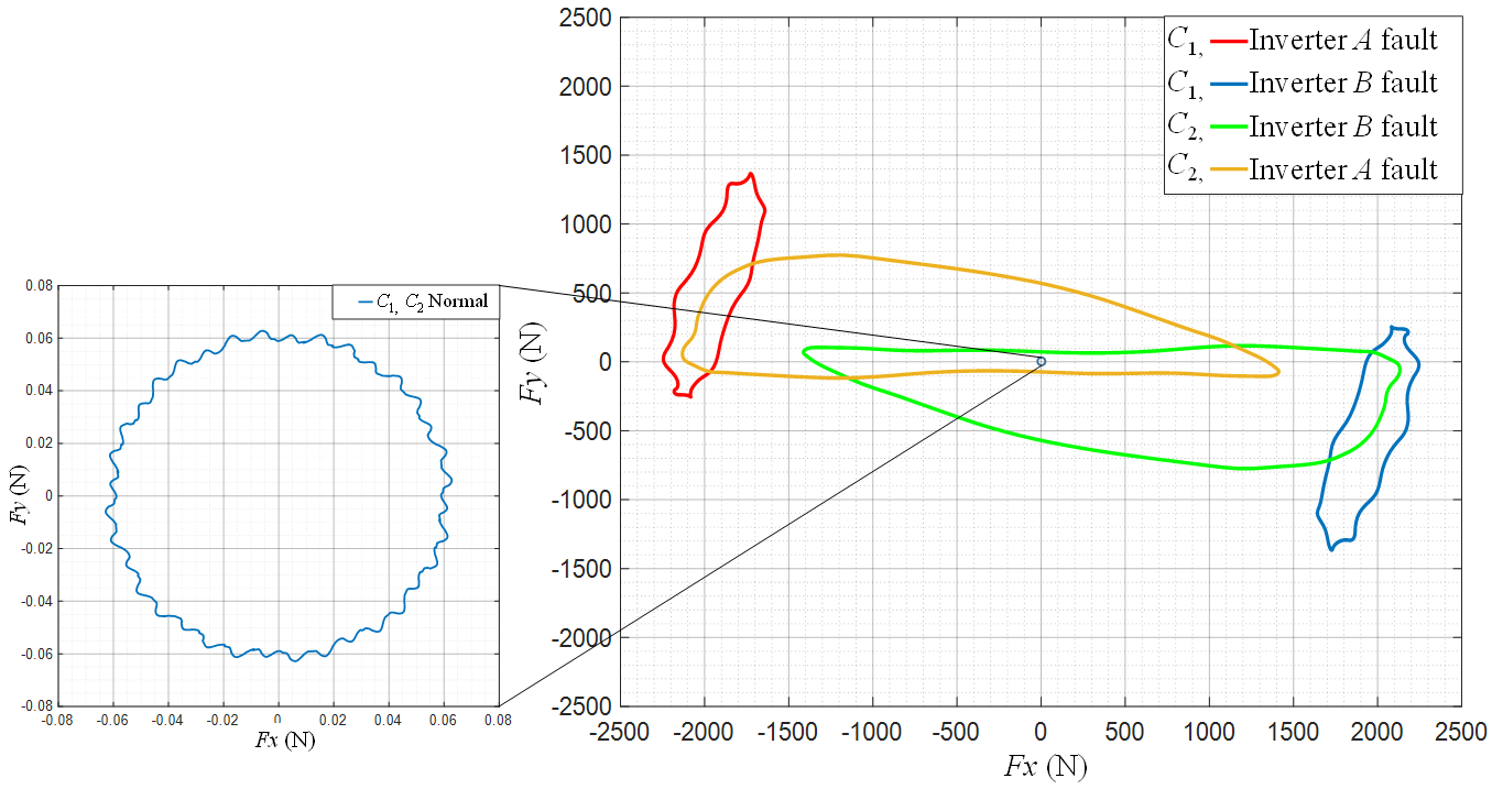
F during one period can be determined. For the studied configurations of the inverter system operation, the determined trajectories of the end of the force
F vector acting on the rotor of the machine over one period of supply current under steady-state conditions are shown in
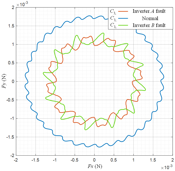
Figure 18 and
Figure 19.
The analysis of the results shows that with proper operation of both inverters, the resultant force acting on the rotor is negligibly small due to the symmetrical distribution of the magnetic field and the balance of radial forces (see
Figure 18 for “
C1,
C2 Normal” and
Figure 19 for “
C3 Normal”). The fault of one of the inverters in the
C1 and
C2 configurations of the three-phase SynRM leads to high asymmetry of the magnetic field distribution and the occurrence of a very large resultant magnetic pull force acting on the rotor exceeding 2 kN—see
Figure 18. Considering configuration
C3, i.e., the SynRM with the proposed six-phase winding, it can be observed that regardless of the operating state of the power supply, the symmetrical distribution of the magnetic field and thus the balance of radial force along the air-gap circumference is achieved—see
Figure 19. This is due to the winding arrangement, which ensures symmetry even when one inverter is operating.
In summary, based on the results of the conducted analysis of electromagnetic torque and magnetic pull forces in the studied SynRMs, it can be stated that only the machine with the proposed six-phase winding is suitable for the operation under fault conditions of one of the inverters, forming the supply system. The decisive factors are the balance of the radial forces and a satisfactory value of the torque, as well as low torque ripples.
5. Preliminary Tests of the Prototype
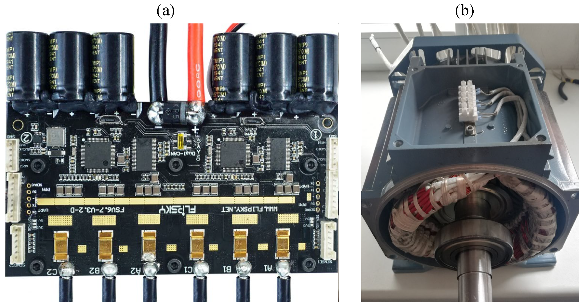
To ensure the correct operation of the proposed six-phase SynRM machine, a control and power supply system enabling the implementation of FOC for the six-phase system is required. Unfortunately, such systems are not available directly on the market. Therefore, the task of adapting the Flipsky 200A ESC Dual FSESC6.7/VESC6 electronic speed controller (ESC) dedicated to controlling two independent
PMSMs was undertaken. The adopted ESC motor and six-phase SynRM prototype are shown in
Figure 20a,b, respectively.
The ESC was chosen mainly due to the availability of six high-current outputs allowing one to power two three-phase motors. This allows the use of structural elements of the controller in the power supply of a six-phase machine by adapting the firmware uploaded to STM32 microprocessors. In this way, the modified system will cooperate with the prototype being constructed. Work has already been undertaken on implementing the six-phase FOC algorithm in the SynRM.
The winding design process of the six-phase winding discussed and defined in
Section 2 and shown in diagram in
Figure 5 was the basis for manufacturing the stator winding of the machine. To confirm the correctness of the winding, EMF was analyzed. The test of the voltage induced in the coils was performed analogously to the approach described in
Section 4. However, an existing rotor with permanent magnets was necessary in this case. For this purpose, a dedicated plastic holder of the magnets in the rotor was designed in the professional CAD package Fusion 360 provided by Autodesk and manufactured by 3D printing technology. The plastic magnet holder after the installation of the permanent magnets is shown in
Figure 21a, while the rotor after its installation in the stator of the machine is shown in
Figure 21b.
The plastic holder of the magnets has 36 flat holes in which neodymium magnets with a dimension of 50 × 5 × 1.6 mm are placed. The rotor has the same axial length as the magnets. To place the rotor in the stator of the machine, it was also necessary to design a shaft and install bearings.
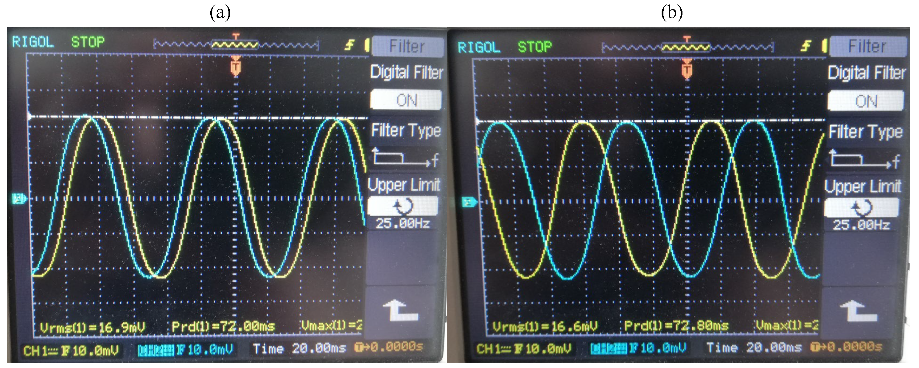
Figure 21b shows the permanent magnet rotor mounted on the shaft and its positioning in the machine stator. After completing the installation of the rotor (the motor installation was completed), the shaft of the machine was driven by the external motor, and the induced voltages were acquired using a digital oscilloscope. The waveforms of the induced voltages recorded by the oscilloscope are shown in
Figure 22.
By analyzing the results of the oscillograms shown in
Figure 22, it can be stated that the winding was wound correctly. In the case of phases
A–D,
C–F, and
B–E, the shift was 30° (
Figure 22a), while between phases
A–B–C and
D–E–F, the shift was 120° (
Figure 22b). This clearly confirms the achievement of the desired asymmetric six-phase system.
6. Conclusions
In this paper, research on the design and analysis of the six-phase winding of a four-pole SynRM is reported. The correctness of the synthesis of the six-phase winding was confirmed by means of finite element analysis as well as measurements of induced voltages on the prototype motor. To facilitate the finite element analysis of the motor performance under load conditions, the extended forward and reverse Clarke transformations enabling the implementation of the FOC algorithm were proposed and validated. The conducted finite element analysis of the motor performance under normal and inverter-fault conditions shows the advantages of the developed six-phase motor in terms of the electromagnetic torque and balance of radial force compared to the reference three-phase SynRM design.
On the basis of the conducted research, it was found that the main advantage of the proposed six-phase winding of the SynRM is better exploitation of the magnetic circuit, showing an increase in torque of 7% compared to the reference machine of the three-phase winding. Additionally, it can be observed that increasing the number of phases slightly reduces the torque ripples.
The analysis of the SynRM performance with a redundant power supply system (enabling redundancy by supplying the machine from two three-phase DC/AC inverters) showed that from the electromagnetic point of view, the proposed six-phase SynRM can properly operate even when one inverter is in a fault state. It has also been demonstrated that in the case of a three-phase machine, due to high torque ripples and the asymmetry of the magnetic field causing an imbalance of radial forces, the operation under inverter-fault conditions is limited. Nevertheless, it should be noted that the studied three-phase SynRM operating under inverter-fault conditions generates greater torque than the machine with the proposed six-phase winding operating under the same inverter-fault conditions.
The SynRM prototype with the developed six-phase winding was built, and a preliminary test was carried out. The measurements of the induced electromotive force using a permanent magnet rotor confirmed the achievement of the asymmetric six-phase system assumed at the winding design stage. The development of a redundant power supply system for the machine, regarding the selection of the dual three-phase electronic speed controller, has been initiated. This is an ongoing task, and the results of the experimental research on the developed machine operation under inverter-fault conditions will be reported in further publications.


