Article

Coordinated Control of Proton Exchange Membrane Electrolyzers and Alkaline Electrolyzers for a Wind-to-Hydrogen Islanded Microgrid

School of Electrical Engineering and Automation, Harbin Institute of Technology, Harbin 150001, China
*
Author to whom correspondence should be addressed.
Energies 2024, 17(10), 2317; https://doi.org/10.3390/en17102317
Submission received: 26 March 2024 / Revised: 29 April 2024 / Accepted: 9 May 2024 / Published: 11 May 2024

Abstract

:
In recent years, the development of hydrogen energy has been widely discussed, particularly in combination with renewable energy sources, enabling the production of “green” hydrogen. With the significant increase in wind power generation, a promising solution for obtaining green hydrogen is the development of wind-to-hydrogen (W2H) systems. However, the high proportion of wind power and electrolyzers in a large-scale W2H system will bring about the problem of renewable energy consumption and frequency stability reduction. This paper analyzes the operational characteristics and economic feasibility of mainstream electrolyzers, leading to the proposal of a coordinated hydrogen production scheme involving both a proton exchange membrane (PEM) electrolyzer and an alkaline (ALK) electrolyzer. Subsequently, a coordinated control based on Model Predictive Control (MPC) is proposed for system frequency regulation in a large-scale W2H islanded microgrid. Finally, simulation results demonstrate that the system under PEM/ALK electrolyzers coordinated control not only flexibly accommodates fluctuating wind power but also maintains frequency stability in the face of large disturbances. Compared with the traditional system with all ALK electrolyzers, the frequency deviation of this system is reduced by 25%, the regulation time is shortened by 80%, and the demand for an energy storage system (ESS) is reduced. The result validates the effectiveness of MPC and the benefits of the PEM/ALK electrolyzers coordinated hydrogen production scheme.

1. Introduction

Currently, to reduce the carbon intensity of electricity production and accelerate the development of a renewable-based power system, there is a significant increase in the number of renewable-energy generation units [1]. Among them, wind energy is receiving considerable attention and is regarded as one of the most promising methods for obtaining environmentally clean energy [2]. However, the current power systems face challenges with insufficient capacity to consume renewable energy generation, leading to wind power curtailment and other phenomena. Hydrogen, as a new type of energy carrier, possesses advantages such as cleanliness, scalable long-term storage capability, and versatile applications [3]. Utilizing renewable energy for hydrogen production can effectively improve the renewable energy consumption [4].
Therefore, renewable-energy-based hydrogen has promising applications in many fields. They have been widely researched for applications such as telecom-tower power supply needs [5], aviation [6], metallurgy decarbonization [7], and chemical production [8]. On the other hand, without the additional costs and risks of grid connection, offshore wind power and high-proportion wind power island microgrids are being utilized to produce hydrogen on a large scale [9]. Therefore, the W2H microgrid has become highly promising.
However, compared with the traditional grids, the W2H microgrid has a higher proportion of renewable energy installed capacity and electricity, leading to reduced inertia [10], insufficient standby capacity of frequency modulation [11], and increased disturbance power [12], which are important reasons for the frequency stability of the grid. As a controllable load, electric hydrogen production shows excellent potential in restraining power fluctuation of renewable energy sources and participating in power grid regulation [13]. Therefore, studying how to fully leverage the regulation capability of renewable-energy-based hydrogen production systems and optimizing system control strategies is currently a research hotspot.
In [14], a two-level hierarchical control is designed for the autonomous wind-based hydrogen production system. It aims to increase the hydrogen production as much as possible without reducing the operative life of the battery bank. In [15], a coordinated control strategy is presented for a hydrogen production system considering the regulation characteristics of the electrolyzer, maintaining power balance in the renewable-based power systems, and mitigating the DC voltage wave motion. In [16], a novel energy dispatching based on MPC is presented for off-grid hybrid systems composed of photovoltaic systems/wind turbines/hydrogen/batteries. In [17], a methodology is presented for multi-objective optimization of wind turbine/battery/electrolyzer systems for decentralized clean hydrogen production, which adapts to low wind speed conditions. It achieves reliable hydrogen supply demand under intermittent wind power generation with minimal production cost and environmental impact. Meng et al. analyzed the operating characteristics of the electrolyzers and fuel cells in depth, then formulated the system energy management strategy, comprehensively considering the operating characteristics of each device [18]. In [19], a control strategy based on segmented fuzzy control is proposed to solve the issue of the low hydrogen production efficiency from wind power, along with the establishment of an optimal scheduling model for W2H systems considering hydrogen production efficiency. The main focus of the cited literature is on the energy management of renewable-based hydrogen production systems on the long-term operational scale, achieving the highest efficiency of the electrolyzer operation, the highest energy utilization rate of the renewable energy, and the lowest hydrogen production cost.
Currently, the research on the renewable-based hydrogen production systems mainly covers two time scales. The research on a short-term operational scale mainly considers the balance of the system power, and the voltage and frequency stability of the renewable-based hydrogen production systems. I.A. Razzhivin et al. investigated the influence of synthetic inertia on the dynamic stability of electric power systems and the transient process as a whole, and proposed a method to enhance the stability of the W2H system by utilizing the synthetic inertia of wind turbines [20]. Jinho Kim maintains system stability by employing grid-forming control on the wind turbines and the DC side of the W2H system. The system achieves maximum efficiency by providing synergistic control between the hydrogen systems and the grid-forming wind-turbine-generator [21]. In [22], a power management method is proposed for a DC microgrid. This method aims to achieve smooth power sharing, reduce current ripple, and ensure system stability under uncertainties arising from renewable energy sources and loads.
In reality, the large-scale electrolyzers used in production are primarily ALK electrolyzers, which have slow dynamic responses. Some studies have taken this characteristic into consideration. In [23], a power allocation and alternate control method is proposed for the electrolyzer array of an off-grid W2H system, considering the operational characteristics of ALK electrolyzers. The control strategy allocates the different electrolytic cells to the specific operation mode based on the fluctuation of wind power prediction to maintain the cell working consistency. In [24], when discussing the strategy of improving the efficiency of hydrogen production based on wind energy through electrolytic cells, the start–stop conditions of ALK electrolyzers are considered. On the other hand, the currently commercially used PEMs do not have the aforementioned drawbacks and are very helpful for supporting grid stability. R.S. et al. analyzed the dynamic hydrogen production characteristics of a PEM electrolyzer coupled with wind power and affirmed the rapid electrical response characteristics of a PEM electrolyzer and its superior matching characteristics with fluctuating power sources [25]. Kang and Duan utilized the characteristics of PEM electrolyzers to enhance the stability and efficiency of the photovoltaic hydrogen production system [26]. In [27], a power management system architecture to achieve voltage stability was designed for a DC microgrid consisting of PEM and ALK electrolyzers, ESS, and a photovoltaic system. There have been numerous studies aimed at maintaining the stability of W2H systems. But, challenges persist, such as system complexity, inefficiency, or the mismatch of dynamic characteristics, which hinder the practical application of large-scale hydrogen production.
The purpose of this study is to realize the renewable energy consumption and support frequency stability of the hydrogen production system, so this study focuses on the coordinated control of multiple units in a short time scale. Many mature control methods are used in hydrogen production systems. In [28], the strategy based on state machine control (SMC) is proposed to achieve coordinated control of the renewable-based hydrogen production systems, which is both simple and reliable. The MPC proposed in [29] effectively handles uncertainties and constraints in the hydrogen production systems. The fuzzy control proposed in [30] simplifies the model design process of the hydrogen production system. Considering that SMC will become complicated with the increase in the scale of a hydrogen production system and fuzzy control depends on actual engineering data [31], MPC was adopted in this study.
This paper fully utilizes the adjustable capability of the electrolyzers and combines the dynamic response characteristics of PEM and ALK electrolyzers. It proposes a coordinated control scheme for PEM and ALK electrolyzers in the W2H islanded microgrid. Considering actual production conditions, utilizing the advantages of MPC in handling constraints ensures the system operates within a safe and efficient operational range. This scheme achieves flexible integration of wind energy resources into the hydrogen production system and enhances the frequency support capability of a high-penetration, renewable energy source islanded microgrid. This scheme can help absorb wind power, reduce the ESS investment for supporting the stability of grid and wind power consumption, which is of scientific interest and has practical application value to the large-scale green hydrogen industry.
The remainder of this paper is organized as follows: the design of the W2H islanded microgrid is given in Section 2, the simulation results are given in Section 3, and the conclusion is given in Section 4.

2. Materials and Methods

2.1. Electrolyzer

At present, ALK and PEM electrolyzer technologies have matured and are poised to become the mainstream choices for large-scale renewable hydrogen production. The performance and economic characteristics of ALK and PEM electrolyzers are shown in Table 1 [32,33,34,35].
It can be observed that the overall technical indicators of ALK and PEM electrolyzers are quite close, with a PEM electrolyzer exhibiting better dynamic response speed, enabling it to dampen the power change in a renewable-energy-based system. The dynamic response speed of ALK electrolyzers is slow, and it is basically difficult to play the same role. However, both the equipment and operational costs of PEM electrolyzers are higher than those of ALK, and PEM electrolyzers also have worse durability than ALK electrolyzers. Considering the performance and economics of ALK and PEM electrolyzers mentioned above, the synergistic hydrogen production using both ALK and PEM electrolyzer technologies can achieve flexible integration of renewable energy, provide frequency support capabilities, and simultaneously reduce the ESS cost for supporting the stability of the grid and wind power consumption. At present, the promising vanadium flow batteries used in the large-scale ESS cost EUR 700–1200 €/kWh [36], which also affects the cost of hydrogen production. Therefore, the scheme can also reduce the cost of the hydrogen production system when the cost of an ESS is higher than the cost difference between PEM and ALK electrolyzers. This scheme will likely emerge as the optimal route for large-scale renewable hydrogen production in the future.
The coordinated control strategy of PEM/ALK electrolyzers employed in this paper considers the dynamic response characteristics of both electrolyzers. It assumes that the PEM load has real-time response capability within the system, while the ALK electrolyzer load has a dynamic response rate of 5%/s. The rapid response capability of a PEM electrolyzer allows it to adapt to rapid changes in system power and provide frequency regulation, thus prioritizing the use of the PEM electrolyzer load for power balance. In practice, the cessation of electrolyzers can impact the safety and economy of industrial production, so this study set the electrolyzers to work at a power range of 20–120%. Theoretically, if a PEM electrolyzer can effectively mitigate system power fluctuations with a higher proportion of ALK electrolyzers, the system’s hydrogen production cost would be lower, making the solution more favorable. However, this paper only investigates the effectiveness of PEM/ALK electrolyzers coordinated control scheme. To simplify matters, the power of PEM and ALK electrolyzers is assumed to be the same.

2.2. Microgrid System Overview

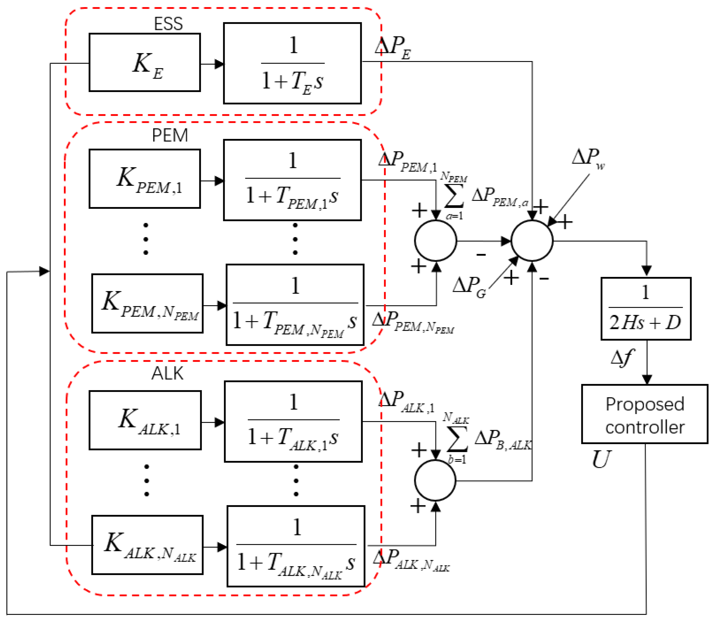
As is shown in Figure 1, this paper investigates a W2H islanded microgrid composed of a micro-generator, wind farms, ALK electrolyzers, PEM electrolyzers, and an ESS. The information and control signals of each unit are accepted and transmitted by the control center. The mathematical schematic of the W2H islanded microgrid is illustrated in Figure 2. In the system studied in this paper, hydrogen production is mainly supplied by wind energy and participates in the load frequency control. Considering the maximum utilization of wind power, wind turbines do not participate in the load frequency control. Instead, their intermittent and fluctuating output is treated as a disturbance variable in the islanded microgrid. When the hydrogen production cannot consume the renewable energy in time, or the renewable energy output is not enough to meet the minimum working conditions of the hydrogen production, the ESS will play a role. Additionally, this study mainly focuses on the supporting capability of load frequency control for the islanded microgrid. Therefore, the generator mainly provides inertia in the system and does not actively respond to power disturbances.
The system is assumed to contain one micro-generator, one ESS, N w wind farms, N A L K ALK electrolyzers, and N P E M PEM electrolyzers. The dynamic of frequency deviation of this system can be described as follows [37]:
Δ f ˙ = D 2 H Δ f 1 2 H ( Δ P G Δ P E Δ P w + a = 1 N P E M Δ P P E M , a + b = 1 N A L K Δ P A L K , b )
where Δ P G , Δ P E , Δ P w , Δ P P E M , a , and Δ P A L K , b represent the variation in the generator, ESS, wind power, PEM electrolyzers, and ALK electrolyzers, respectively; H and D represent the inertia constant of the generator and the load-damping coefficient, respectively.
The system mainly contributes to the control of load frequency through the coordinated control of the ALK electrolyzers, PEM electrolyzers, and ESS. The power variations of these three components exhibit similar dynamic characteristics within the system, as represented in the frequency domain below [38]:
Δ P E ( s ) = K E 1 + T E s U ( s )
Δ P P E M , a ( s ) = K P E M , a 1 + T P E M , a s U ( s )
Δ P A L K , b ( s ) = K A L K , b 1 + T A L K , b s U ( s )
where, K P E M , a , K A L K , b , and T P E M , a , T A L K , b represent the dynamic response coefficient and time constant of ALK and PEM electrolyzers, respectively; K E and T E denote the charge and discharge coefficient and time constant of the ESS, respectively; U represents the control signal received from the control center.
Assuming we ignore the time delay caused by communication links, the dynamic characteristics in the time domain are described as follows:
Δ P ˙ E = 1 T E Δ P E + K E T E U
Δ P ˙ P E M , a = 1 T P E M , a Δ P P E M , a + K P E M , a T P E M , a U
Δ P ˙ A L K , b = 1 T A L K , b Δ P A L K , b + K A L K , b T A L K , b U

2.3. Model Predictive Control

Model Predictive Control relies on a dynamic model of the system to predict state variables to control output. Combining the optimization process with the ability to deal with constraints within a limited time frame makes MPC a suitable choice for controlling complex systems. The MPC calculates future control signals by optimizing a cost function that includes the system model as well as the current and past signals of the system [39].
This paper utilizes the MPC method to generate control signals for the W2H system, contributing to the frequency regulation while optimizing a suitable cost function. Various constraint conditions are also considered during the optimization of the cost function, such as power constraints and power variation rate constraints of the electrolyzers.
From Equations (1), and (5) to (7), the following discrete-time state-space equation can be derived [40,41]:
{ x ( k + 1 ) = A x ( k ) + B U ( k ) + D Δ P w ( k ) f = C x ( k )
where x ( k ) = [ Δ f , Δ P G , Δ P E , Δ P A L K , 1 , , Δ P A L K , N A L K , Δ P P E M , 1 , , Δ P P E M , N P E M ] T represents the vector of system state variables. A , B , C , and D represent the matrices given as follows:
A = [ D 2 H 1 2 H 1 2 H 1 2 H 1 2 H 1 2 H 1 2 H 1 R * T g 1 T g 0 0 0 0 0 0 0 1 T E 0 0 0 0 0 0 0 1 T A L K , 1 0 0 0 0 0 0 0 1 T A L K , N A L K 0 0 0 0 0 0 0 1 T P E M , 1 0 0 0 0 0 0 0 1 T P E M , N P E M ] ,
B = [ 0 K g K E K A L K , 1 K A L K , N A L K K P E M , 1 K P E M , N P E M ] ,   C = [ 1 0 0 ] ,   D = [ 1 2 H 0 0 ]
The above model is used to predict the system response over three prediction horizons. After receiving the measured value f, the MPC provides a control signal U to ensure that the system output f approaches the reference output fref as closely as possible with the minimum control effort. Then, setting the reference value to zero, the control signal is generated to achieve the optimal value for the following objective function:
min U k = 0 p Q f ( f ( k + 1 ) f r e f ( k + 1 ) ) 2 + k = 0 c Q U ( Δ U ( k ) ) 2
where Qf and QU represent the weighting factors assigned to the input and output of the MPC, respectively; p and c represent the prediction and control horizons, respectively. And, the ESS power, the power, and power variation rate of ALK and PEM electrolyzers are subjected to the following constraints:
P E , min P E P E , max
P P E M , a , min P P E M , a P P E M , a , max
Δ P P E M , a , min Δ P P E M , a Δ P P E M , a , max , a = 1 , 2 , N P E M
P A L K , b , min P A L K , b P A L K , b , max
Δ P A L K , b , min Δ P A L K , b Δ P A L K , b , max , b = 1 , 2 , N A L K
P min < a = 1 N P E M P P E M , a + b = 1 N A L K P A L K , b < P max
where P E , min , P E , max , P P E M , a , min , P P E M , a , max , P A L K , b , min , and P A L K , b , max limit the minimum and maximum values of the ESS, each PEM electrolyzer, and each ALK electrolyzer power output over the prediction and control horizons, respectively; Δ P P E M , a , min , Δ P P E M , a , max , Δ P A L K , b , min and Δ P A L K , b , max limit the minimum and maximum values of each PEM electrolyzer and each ALK electrolyzer power variation within each control and prediction horizon, used to constrain the power variation rate, respectively. Each PEM and ALK electrolyzer independently establish their upper and lower limits for output, as well as constraints on the rate of variation. P min and P max limit the minimum and maximum values of the total power of all electrolytic cells.

2.4. Verification Scenario

To validate the effectiveness of the PEM/ALK electrolyzers coordinated control scheme proposed in this paper, the system simulation model was built as shown in Figure 1 using Matlab/Simulink R2023a. The simulation model contains three PEMs and three ALK electrolyzers, with a rated power ratio of 2:2:1, having different constraint conditions. For details about simulation parameters, see Appendix A.
In the simulation, the disturbances are classified into two categories: the power consumed by loads and the power generated by wind farms. Both are randomly generated. To disturb the system highly, two opposing square wave signals are added in the load disturbance. Subsequently, simulation analysis will be conducted separately for the two types of interference in the system.

3. Results

3.1. Results under Wind Power Disturbance

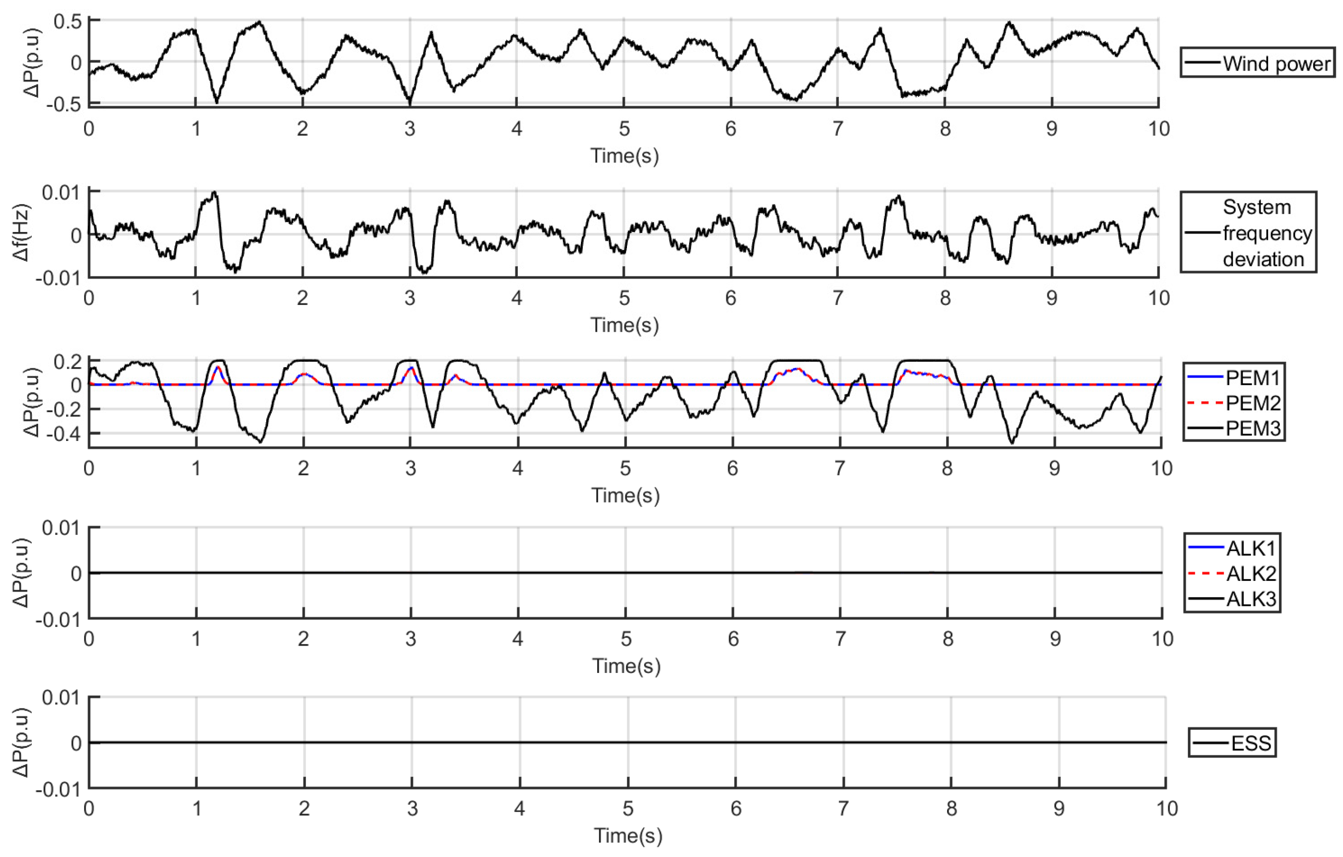
The simulation results under wind power disturbances are presented in Figure 3, illustrating the wind power disturbance, the frequency deviation of the system, and the power variations of the PEM electrolyzers, ALK electrolyzers, and ESS. The power waveforms shown in the figure are presented relative to the increase or decrease in system power. Therefore, in the wind power waveform, positive values indicate insufficient system power, meaning a decrease in wind power generation, requiring a corresponding decrease in power for hydrogen production loads. Negative values indicate surplus system power, meaning an increase in wind power generation, requiring a corresponding increase in power for hydrogen production loads. Throughout the entire simulation period of 0–10 s, the wind power fluctuates between −0.4 and 0.4 p.u. When the wind power fluctuates between −0.2 and 0.4 p.u, PEM3 responds promptly, dampening the power fluctuations and maintaining system frequency stability. When the wind power fluctuates between −0.4 and −0.2 p.u, PEM3 reaches its maximum operating power limit and still cannot absorb the excess system power. At this point, PEM1 and PEM2 increase their operating power to collectively dampen the system power fluctuations and maintain system frequency stability. Throughout the process, as the PEM electrolyzer is sufficient to dampen wind power fluctuations, the ALK electrolyzers and ESS experience minimal power changes, still keeping the maximum frequency deviation of the system below 0.01 Hz, maintaining system stability.
As a comparison, replacing the PEM electrolyzers with ALK electrolyzers in the system while maintaining other conditions as the same, the system response is shown in Figure 4. It can be observed that in the face of wind power fluctuations, due to its limited dynamic response speed, the ALK electrolyzers cannot dampen power fluctuations. The participation of the ESS is required to maintain the frequency stability of the system. During this process, the maximum frequency deviation of the system exceeds 0.02 Hz, and the maximum power of ESS reaches 0.5 p.u. Compared with Figure 3, the ability of the all-ALK-electrolyzer W2H system to dampen wind power fluctuations is poorer, and the system frequency stability is also inferior. To enhance the frequency stability of the system, it is necessary to increase the ESS capacity or replace the ALK electrolyzers with more flexible controllable loads. Considering hydrogen production efficiency and system responsiveness, replacing some ALK electrolyzers with PEMs is evidently beneficial.

3.2. Results under Large Load Disturbance

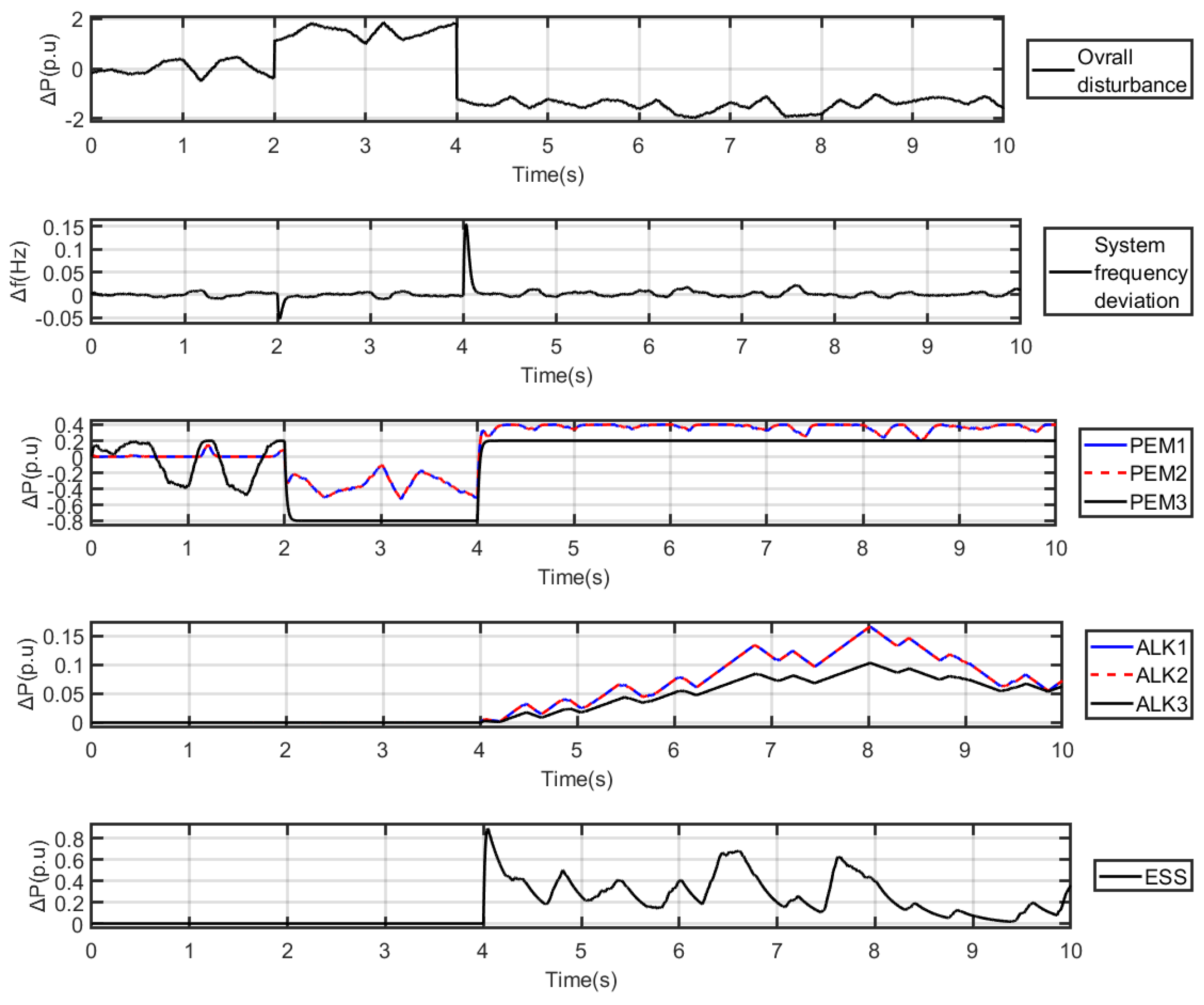
On top of the wind power disturbance, step load disturbances of ±1.5 p.u are introduced at 2 s and 4 s, respectively. The simulation results, shown in Figure 5, illustrate the overall disturbances, frequency deviations, and the power variations of the PEM electrolyzers, ALK electrolyzers, and ESS. From 0 to 2 s, during disturbances caused by wind power fluctuations, the power of PEM3, with its lower rated power, varies accordingly to maintain system frequency stability. At this point, the PEM electrolyzer responds promptly to mitigate the impact of wind power fluctuations, thereby essentially maintaining the system frequency deviation, while the power of the other PEM electrolyzers, ALK electrolyzers, and ESSs remain relatively constant. At 2 s, there is a sudden increase in system load power, resulting in a drop in system frequency. The power of all three PEMs decreases accordingly, with the power of PEM3 reduced to the minimum operating level. Consequently, the system frequency stabilizes within a short time. From 2 to 4 s, to maintain system frequency stability, PEM1 and PEM2 will adjust their power output in response to the wind power disturbance, as PEM3 has reached its minimum operating power. At 4 s, the system load power suddenly decreases, causing the system frequency to rise. The power of all three PEMs quickly increases to the upper limit of their operating power, yet they are unable to suppress the system’s power variations. At this point, the power of all three ALK electrolyzers increases slowly due to dynamic response speed limitations, while ESS charges to consume excess system power, maintaining system frequency stability. As the power of the ALK electrolyzers increase, the power of the ESS decreases accordingly until ESS stops charging. From 4 to 10 s, facing wind power disturbance, the operating power of PEMs reach their upper limit, thus, mainly relying on the ALK electrolyzers and ESS to dampen system power fluctuations, effectively maintaining system frequency stability. During these events, the power variation limits for PEM1 and PEM2 range from +0.4 to −1.6, and for PEM3 from +0.2 to −0.8, allowing for immediate response to system changes. The power variation limits for ALK1 and ALK2 range from +0.4 to −1.6, with a power variation rate below 0.1 per second, while for ALK3, the limits range from +0.2 to −0.8, with a power variation rate below 0.05 per second. Throughout the process, the maximum frequency deviation of the system remains below 0.15 Hz, with a frequency regulation time of less than 0.2 s.
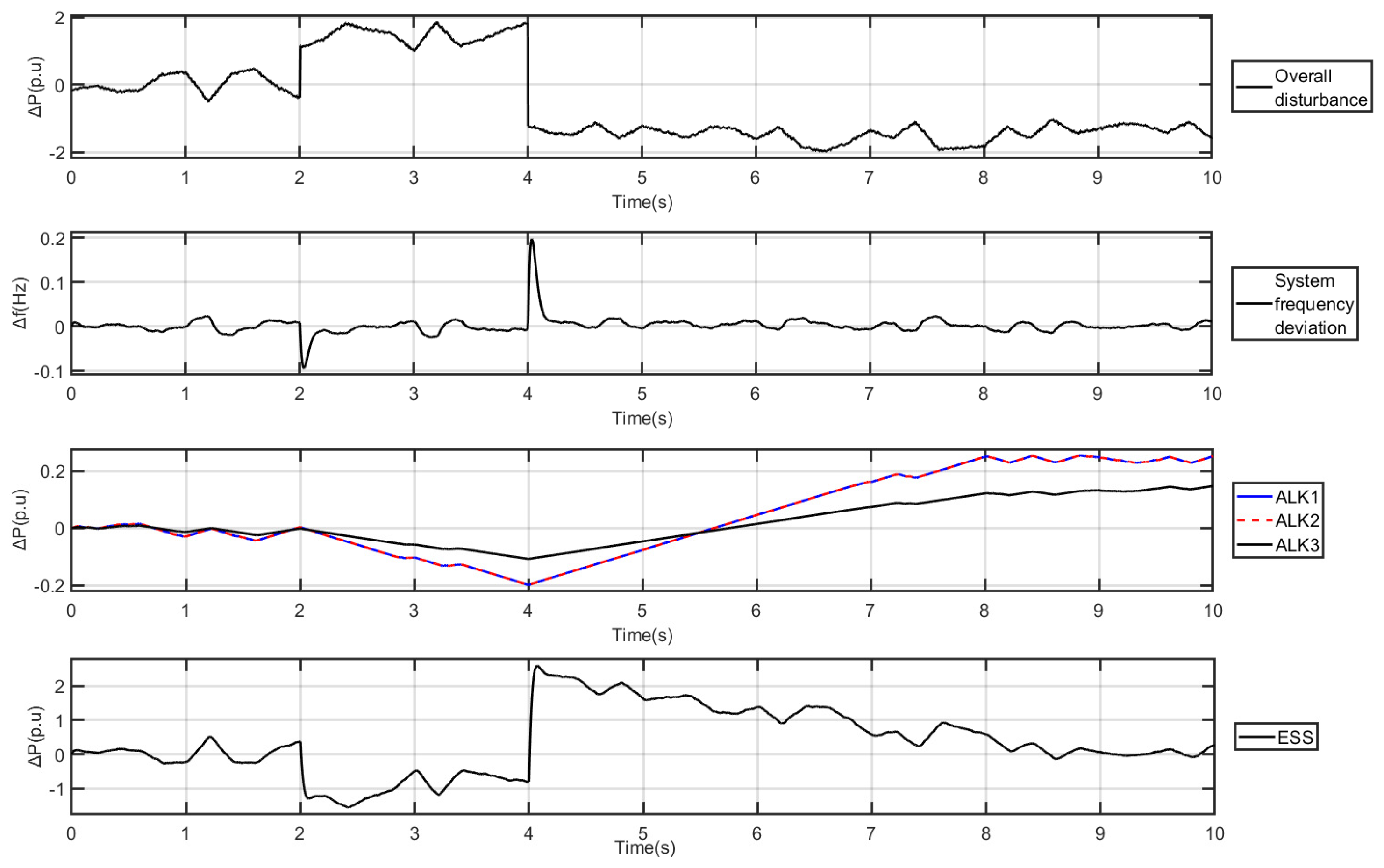
Similarly, when replacing the PEM electrolyzers with ALK electrolyzers for comparison, the system response is shown in Figure 6. It can be observed that, when encountering wind power disturbances, the ALK electrolyzers and ESS can mitigate the power variations in the system, maintaining the system frequency as stable. However, when large load disturbances occur, such as at 4 s, when the system load power suddenly drops, due to the limited dynamic response speed of the ALK electrolyzers, their power can only increase slowly. To absorb the excess power in the system and maintain system frequency stability, the charging power of the ESS quickly rises, followed by a slow decline as the power of the ALK electrolyzers increases. During this process, the maximum frequency deviation of the system reaches 0.2 Hz, and the frequency regulation time exceeds 1 s, indicating that the frequency stability of the system is not as good, as shown in Figure 5. Moreover, to maintain system stability, the maximum charging power of the ESS reaches 2.5 p.u, significantly higher than the 0.8 p.u shown in Figure 5. Compared with Figure 5, the all-ALK-electrolyzer W2H system has inferior ability to face the load step disturbance frequency, and the frequency stability of the system is also poor. The conclusions drawn can be similarly derived in Section 3.1 after comparison.

4. Discussion

The simulation results in Figure 3, Figure 4, Figure 5 and Figure 6 demonstrate the effectiveness and benefit of the proposed PEM/ALK electrolyzer coordinated control scheme in stabilizing the W2H islanded microgrid. By leveraging the dynamic response characteristics of the PEM and ALK electrolyzers [3,33], the system can consume wind power in time while maintaining frequency stability in the face of both small disturbances and large disturbances caused by wind power and loads in the system. Some parameters of the results are shown in Table 2. Compared with the traditional system with all ALK electrolyzers, the frequency deviation of PEM/ALK electrolyzer coordinated control is reduced by 25% and the regulation time is shortened by 80%, showing that PEM/ALK electrolyzer coordinated control has better dynamic response capability and can better support the frequency stability of the system. In addition, the system using PEM/ALK electrolyzer coordinated control requires less ESS power than the conventional systems, indicating that this control can reduce the ESS investment in the W2H system. If the cost of the ESS is higher than the cost difference between the PEM and ALK electrolyzers, further optimization of PEM and ALK electrolyzer configurations in this simulation will result in lower hydrogen production costs.
Considering the complexity of the electrolyzer’s start–stop process, the safety of the hydrogen production process, and its impact on the system’s economy [2,3], it is commonly assumed that all electrolyzers in the system are operating normally and are kept running continuously [15]. Therefore, upper and lower limits are set for the power variation of the electrolyzers and the ESS is added to ensure the stable operation of the system. Since operating the electrolyzers at the rated power maximizes hydrogen production efficiency, and repeated fluctuations in electrolyzer power can reduce hydrogen production efficiency, the optimal control in the result is to initiate power changes in the electrolyzers with smaller ratings first. These conditions are all derived from comprehensive consideration of actual production and reflected in simulation, thus possessing practical reference value for production.

5. Conclusions

In this paper, through analyzing the performance and economic characteristics of different electrolyzers, a coordinated hydrogen production scheme of PEM and ALK electrolyzers is proposed by leveraging the superior dynamic response characteristics of PEM electrolyzers and the lower hydrogen production cost of ALK electrolyzers. This scheme aims to realize wind power consumption and frequency regulation through electrolyzers, which have more advantages in efficiency and cost in hydrogen production than schemes relying on the ESS and wind power standby. Based on the PEM/ALK electrolyzer coordinated control and considering the advantages and disadvantages of different controls, MPC for a large-scale W2H islanded microgrid is defined for system frequency regulation, and the operating conditions and constraints of each component are considered. The results of this study show that the system with the PEM/ALK electrolyzer coordinated control can not only flexibly accommodate fluctuating wind power but also support the system’s frequency in the face of disturbances. Compared with the traditional system with all ALK electrolyzers, the frequency deviation of this system is reduced by 25%, the regulation time is shortened by 80%, and the demand for the ESS is reduced. The simulation result validates the effectiveness of MPC and the benefits of the PEM/ALK electrolyzer coordinated hydrogen production scheme.
This proposed hydrogen production system can help absorb wind power and respond quickly, directly supporting grid stability and indirectly improving the efficiency and cost of hydrogen production. The ESS power demand of the solution is lower than that of other solutions. Therefore, when the frequency regulation capacity is equal and the PEM/ALK electrolyzer configuration is optimal, this scheme can reduce the scale of the ESS in the system, and lower the investment cost of the ESS, thus reducing the overall cost of hydrogen production if the ESS cost is higher than the PEM/ALK electrolyzer differential. Moreover, considering the actual production conditions, such as the minimum supply demand for hydrogen, each module is constrained, which is of scientific significance and has practical application value for the safe and economical production of the large-scale green hydrogen industry.
As future work, optimization of PEM and ALK electrolyzer configuration in the system and improvements to MPC will be investigated to achieve the best economic and control performance while fulfilling the functions mentioned above. On the other hand, by approaching the actual production situation more closely, such as integrating areas like hydrogen storage and chemical production, we can research hydrogen production strategies in more complex systems.

Author Contributions

Conceptualization, Z.L., Z.T., Z.Y. and Y.X.; methodology, Z.L., Z.T., Z.Y. and Y.X.; software, Z.L., Z.T. and Z.Y.; validation, Z.L., Z.T. and Z.Y.; formal analysis, Z.L., Z.T. and Z.Y.; resources, Y.X., Z.Y. and Z.T.; writing—original draft preparation, Z.L., Z.T., Z.Y. and Y.X.; writing—review and editing, Z.L., Z.T., Z.Y. and Y.X.; supervision, Z.Y. and Y.X.; project administration, Y.X. All authors have read and agreed to the published version of the manuscript.

Funding

This study is supported by science and technology project of the State Grid Corporation of China (5100-202399366A-2-2-ZB).

Data Availability Statement

The data are not publicly available due to confidentiality reasons.

Conflicts of Interest

The authors declare no conflicts of interest.

Nomenclature

SymbolName Unit
f System frequency
Δ f Frequency deviation
H Generator inertia constant
D Load-damping coefficient
Δ P G Generator power deviation
Δ P E Energy storage system power deviation
Δ P w Wind power deviation
Δ P P E M , a PEM electrolyzer power deviation
Δ P A L K , b ALK electrolyzer power deviation
K E Charge and discharge coefficient
K P E M , a Dynamic response coefficient of PEM electrolyzers
K A L K , b Dynamic response coefficient of ALK electrolyzers
T E Time constant of energy storage system
T P E M , a Time constant of PEM electrolyzers
T A L K , b Time constant of ALK electrolyzers
U Control signal
Q f Weight on the input signal
Q U Weight on the output signal
p Prediction horizons
c Control horizons

Appendix A. System Parameters

ParametersValueParametersValue
D 1 T A L K 1 ,   T A L K 2 ,   T A L K 3 0.02
H 0.1 K g 1
R 2.5 K E 20
T g 1 K P E M 1 ,   K P E M 2 ,   K P E M 3 30
T E 0.03 K A L K 1 ,   K A L K 2 ,   K A L K 3 30
T P E M 1 ,   T P E M 2 ,   T P E M 3 0.02 T s 0.001

References

  1. Saint Akadiri, S.; Alola, A.A.; Akadiri, A.C.; Alola, U.V. Renewable Energy Consumption in EU-28 Countries: Policy toward Pollution Mitigation and Economic Sustainability. Energy Policy 2019, 132, 803–810. [Google Scholar] [CrossRef]
  2. Ameyaw, B.; Li, Y.; Ma, Y.; Agyeman, J.K.; Appiah-Kubi, J.; Annan, A. Renewable Electricity Generation Proposed Pathways for the US and China. Renew. Energy 2021, 170, 212–223. [Google Scholar] [CrossRef]
  3. Li, Z.; Guo, P.; Han, R.; Sun, H. Current Status and Development Trend of Wind Power Generation-Based Hydrogen Production Technology. Energy Explor. Exploit. 2019, 37, 5–25. [Google Scholar] [CrossRef]
  4. Trattner, A.; Höglinger, M.; Macherhammer, M.; Sartory, M. Renewable Hydrogen: Modular Concepts from Production over Storage to the Consumer. Chem. Ing. Tech. 2021, 93, 706–716. [Google Scholar] [CrossRef]
  5. Aliberti, P.; Sorrentino, M.; Califano, M.; Pianese, C.; Capozucca, L.; Cristiani, L.; Lops, G.; Mancini, R. Modelling Methodologies to Design and Control Renewables and Hydrogen-Based Telecom Towers Power Supply Systems. Energies 2023, 16, 6316. [Google Scholar] [CrossRef]
  6. Hoelzen, J.; Silberhorn, D.; Zill, T.; Bensmann, B.; Hanke-Rauschenbach, R. Hydrogen-Powered Aviation and Its Reliance on Green Hydrogen Infrastructure—Review and Research Gaps. Int. J. Hydrogen Energy 2022, 47, 3108–3130. [Google Scholar] [CrossRef]
  7. Shahabuddin, M.; Brooks, G.; Rhamdhani, M.A. Decarbonisation and Hydrogen Integration of Steel Industries: Recent Development, Challenges and Technoeconomic Analysis. J. Clean. Prod. 2023, 395, 136391. [Google Scholar] [CrossRef]
  8. Yang, S.; Peng, S.; Ling, X. Discussion on the Feasibility of the Integration of Wind Power and Coal Chemical Industries for Hydrogen Production. Sustainability 2021, 13, 11628. [Google Scholar] [CrossRef]
  9. Hexu, S.; Zheng, L.; Aibing, C.; Yan, Z.; Chunxiao, M. Current status and development trend of hydrogen production technology by wind power. Trans. China Electrotech. Soc. 2019, 34, 4071–4083. [Google Scholar] [CrossRef]
  10. Xie, X.; He, J.; Mao, H.; Li, H. New issues and classification of power system stability with high shares of renewables and power electronics. Proc. CSEE 2021, 41, 461–475. [Google Scholar] [CrossRef]
  11. Heylen, E.; Teng, F.; Strbac, G. Challenges and Opportunities of Inertia Estimation and Forecasting in Low-Inertia Power Systems. Renew. Sustain. Energy Rev. 2021, 147, 111176. [Google Scholar] [CrossRef]
  12. Eftekharnejad, S.; Vittal, V.; Heydt, G.T.; Keel, B.; Loehr, J. Small Signal Stability Assessment of Power Systems with Increased Penetration of Photovoltaic Generation: A Case Study. IEEE Trans. Sustain. Energy 2013, 4, 960–967. [Google Scholar] [CrossRef]
  13. Eichman, J.; Harrison, K.; Peters, M. Novel Electrolyzer Applications: Providing More Than Just Hydrogen; No. NREL/TP-5400-61758; National Renewable Energy Lab. (NREL): Golden, CO, USA, 2014; p. 1159377.
  14. Valenciaga, F.; Evangelista, C.A. Control Design for an Autonomous Wind Based Hydrogen Production System. Int. J. Hydrogen Energy 2010, 35, 5799–5807. [Google Scholar] [CrossRef]
  15. Guo, X.; Kang, P.; Zhang, J.; Song, P.; Yang, G. Coordinated Control Strategy for System of Hydrogen Production from Renewable Energy Considering Regulating Characteristics of Electrolyzers. J. Phys. Conf. Ser. 2023, 2659, 012029. [Google Scholar] [CrossRef]
  16. Torreglosa, J.P.; García, P.; Fernández, L.M.; Jurado, F. Energy Dispatching Based on Predictive Controller of an Off-Grid Wind Turbine/Photovoltaic/Hydrogen/Battery Hybrid System. Renew. Energy 2015, 74, 326–336. [Google Scholar] [CrossRef]
  17. Tebibel, H. Methodology for Multi-Objective Optimization of Wind Turbine/Battery/Electrolyzer System for Decentralized Clean Hydrogen Production Using an Adapted Power Management Strategy for Low Wind Speed Conditions. Energy Convers. Manag. 2021, 238, 114125. [Google Scholar] [CrossRef]
  18. Meng, Z.; He, Q.; Shi, X.; Cao, D.; Du, D. Research on Energy Utilization of Wind-Hydrogen Coupled Energy Storage Power Generation System. Sep. Purif. Technol. 2023, 313, 123439. [Google Scholar] [CrossRef]
  19. Hong, Z.; Wei, Z.; Han, X. Optimization Scheduling Control Strategy of Wind-Hydrogen System Considering Hydrogen Production Efficiency. J. Energy Storage 2022, 47, 103609. [Google Scholar] [CrossRef]
  20. Razzhivin, I.A.; Andreev, M.V.; Kievec, A.V. Increasing the Stability of Hydrogen Production in the Wind Energy-Hydrogen System through the Use of Synthetic Inertia of the Wind Turbine. Int. J. Hydrogen Energy 2022, 47, 38495–38505. [Google Scholar] [CrossRef]
  21. Kim, J.; Muljadi, E.; Nelms, R.M. Modelling and Control Coordination Scheme of a Wind-to-hydrogen Set for Future Renewable-based Power Systems. IET Renew. Power Gener. 2020, 14, 3317–3326. [Google Scholar] [CrossRef]
  22. Zhang, M.; Xu, Q. An MPC Based Power Management Method for Renewable Energy Hydrogen Based DC Microgrids. In Proceedings of the 2023 IEEE Applied Power Electronics Conference and Exposition (APEC), Orlando, FL, USA, 19–23 March 2023; IEEE: Piscataway, NJ, USA, 2023; pp. 577–581. [Google Scholar]
  23. Zhao, Y.; Zhu, Z.; Tang, S.; Guo, Y.; Sun, H. Electrolyzer Array Alternate Control Strategy Considering Wind Power Prediction. Energy Rep. 2022, 8, 223–232. [Google Scholar] [CrossRef]
  24. Garcia-Torres, F.; Valverde, L.; Bordons, C. Optimal Load Sharing of Hydrogen-Based Microgrids with Hybrid Storage Using Model-Predictive Control. IEEE Trans. Ind. Electron. 2016, 63, 4919–4928. [Google Scholar] [CrossRef]
  25. Sarrias-Mena, R.; Fernández-Ramírez, L.M.; García-Vázquez, C.A.; Jurado, F. Electrolyzer Models for Hydrogen Production from Wind Energy Systems. Int. J. Hydrogen Energy 2015, 40, 2927–2938. [Google Scholar] [CrossRef]
  26. Kang, Z.; Duan, F. A Flexible Load Adaptive Control Strategy for Efficient Photovoltaic Hydrogen Generation System. Sol. Energy 2023, 266, 112150. [Google Scholar] [CrossRef]
  27. K/bidi, F.; Damour, C.; Grondin, D.; Hilairet, M.; Benne, M. Power Management of a Hybrid Micro-Grid with Photovoltaic Production and Hydrogen Storage. Energies 2021, 14, 1628. [Google Scholar] [CrossRef]
  28. Villa Londono, J.E.; Mazza, A.; Pons, E.; Lok, H.; Bompard, E. Modelling and Control of a Grid-Connected RES-Hydrogen Hybrid Microgrid. Energies 2021, 14, 1540. [Google Scholar] [CrossRef]
  29. Kumar, K.; Alam, M.; Dutta, V. Energy Management Strategy for Integration of Fuel Cell-Electrolyzer Technologies in Microgrid. Int. J. Hydrogen Energy 2021, 46, 33738–33755. [Google Scholar] [CrossRef]
  30. Abadlia, I.; Bahi, T.; Bouzeria, H. Energy Management Strategy Based on Fuzzy Logic for Compound RES/ESS Used in Stand-Alone Application. Int. J. Hydrogen Energy 2016, 41, 16705–16717. [Google Scholar] [CrossRef]
  31. Pei, W.; Zhang, X.; Deng, W.; Tang, C.; Yao, L. Review on Operation Control Strategy of DC Microgrid with Electric-Hydrogen Hybrid Storage System. CSEE J. Power Energy Syst. 2022, 8, 329–346. [Google Scholar] [CrossRef]
  32. Buttler, A.; Spliethoff, H. Current Status of Water Electrolysis for Energy Storage, Grid Balancing and Sector Coupling via Power-to-Gas and Power-to-Liquids: A Review. Renew. Sustain. Energy Rev. 2018, 82, 2440–2454. [Google Scholar] [CrossRef]
  33. Shen, X.; Zhang, X.; Li, G.; Lie, T.T.; Hong, L. Experimental Study on the External Electrical Thermal and Dynamic Power Characteristics of Alkaline Water Electrolyzer. Int. J. Energy Res. 2018, 10, 3244–3257. [Google Scholar] [CrossRef]
  34. Brauns, J.; Turek, T. Alkaline Water Electrolysis Powered by Renewable Energy: A Review. Processes 2020, 8, 248. [Google Scholar] [CrossRef]
  35. Miller, H.A.; Bouzek, K.; Hnat, J.; Loos, S.; Bernäcker, C.I.; Weißgärber, T.; Röntzsch, L.; Meier-Haack, J. Green Hydrogen from Anion Exchange Membrane Water Electrolysis: A Review of Recent Developments in Critical Materials and Operating Conditions. Sustain. Energy Fuels 2020, 4, 2114–2133. [Google Scholar] [CrossRef]
  36. Yu, Z.; Jia, X.; Cai, Y.; Su, R.; Zhu, Q.; Zhao, T.; Jiang, H. Electrolyte Engineering for Efficient and Stable Vanadium Redox Flow Batteries. Energy Storage Mater. 2024, 69, 103404. [Google Scholar] [CrossRef]
  37. Bevrani, H.; Feizi, M.R.; Ataee, S. Robust Frequency Control in an Islanded Microgrid: H∞ and μ-Synthesis Approaches. IEEE Trans. Smart Grid 2015, 7, 706–717. [Google Scholar] [CrossRef]
  38. Xing, L.; Mishra, Y.; Tian, Y.-C.; Ledwich, G.; Su, H.; Peng, C.; Fei, M. Dual-Consensus-Based Distributed Frequency Control for Multiple Energy Storage Systems. IEEE Trans. Smart Grid 2019, 10, 6396–6403. [Google Scholar] [CrossRef]
  39. Mayne, D.Q.; Rawlings, J.B.; Rao, C.V.; Scokaert, P.O.M. Constrained Model Predictive Control: Stability and Optimality. Automatica 2000, 36, 789–814. [Google Scholar] [CrossRef]
  40. Oshnoei, A.; Kheradmandi, M.; Muyeen, S.M. Robust Control Scheme for Distributed Battery Energy Storage Systems in Load Frequency Control. IEEE Trans. Power Syst. 2020, 35, 4781–4791. [Google Scholar] [CrossRef]
  41. Sockeel, N.; Gafford, J.; Papari, B.; Mazzola, M. Virtual Inertia Emulator-Based Model Predictive Control for Grid Frequency Regulation Considering High Penetration of Inverter-Based Energy Storage System. IEEE Trans. Sustain. Energy 2020, 11, 2932–2939. [Google Scholar] [CrossRef]
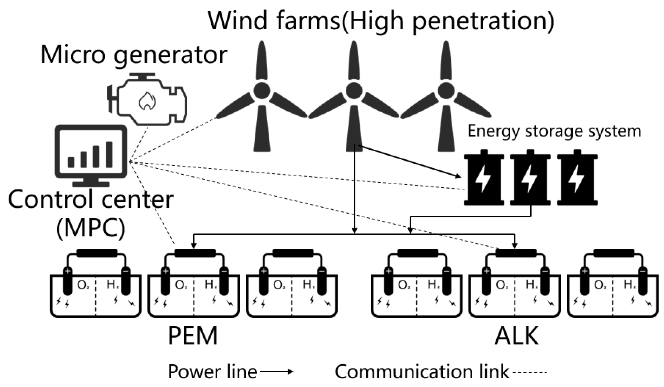
Figure 1. Schematic of the W2H islanded microgrid.
Energies 17 02317 g001
Figure 2. Frequency response model of the W2H islanded microgrid.
Energies 17 02317 g002
Figure 3. Dynamic response of the deviation of wind power, system frequency, PEM electrolyzer power, ALK electrolyzer power, and ESS power under wind power disturbance.
Energies 17 02317 g003
Figure 4. Replacing PEM electrolyzers with ALK electrolyzers dynamic response of the deviation of wind power, system frequency, ALK electrolyzer power, and ESS power under wind power disturbance.
Energies 17 02317 g004
Figure 5. Dynamic response of the deviation of wind power, system frequency, PEM electrolyzer power, ALK electrolyzer power, and ESS power under large load disturbance.
Energies 17 02317 g005
Figure 6. Replacing PEM electrolyzers with ALK electrolyzers, dynamic response of the deviation of wind power, system frequency, ALK electrolyzer power, and ESS power under large load disturbance.
Energies 17 02317 g006
Table 1. Comparison of ALK and PEM electrolyzers, and classification by advantages.
Performance and Economic CharacteristicsALKPEM
ALK BetterLifetime (kh)55–12060–100
Efficiency degradation (%/a)0.25–1.50.5–2.5
Investment costs (€/kW)800–15001400–2100
Maintenance costs (% of investment costs per year)2–33–5
Nominal stack efficiency (%)63–7160–68
PEM BetterLoad flexibility (% of nominal load)20–1200–120
Cell area (m2)<3.6<0.13
Typical pressure (bar)10–3050–80
Hydrogen purity (%)99.8>99.99
System responseSecondsMilliseconds
Operating temperature (°C)60–8050–80
Table 2. Comparison of the parameters of PEM/ALK electrolyzers and all-ALK- electrolyzer control schemes in the two scenarios.
ScenarioParametersPEM/ALKAll ALK
Under wind power disturbanceMax frequency deviation (Hz)0.010.02
Max absolute ESS power (p.u)00.5
Under large load disturbanceMax frequency deviation (Hz)0.150.2
Max absolute ESS power (p.u)0.82.5
Max regulation time (s)0.21
Disclaimer/Publisher’s Note: The statements, opinions and data contained in all publications are solely those of the individual author(s) and contributor(s) and not of MDPI and/or the editor(s). MDPI and/or the editor(s) disclaim responsibility for any injury to people or property resulting from any ideas, methods, instructions or products referred to in the content.