1. Introduction
Methods of increasing the efficiency of the heat exchange process include a wide range of procedures, which are mainly focused on different approaches in terms of the choice and modification of the properties of the working medium [
1,
2], the material composition and configuration of the individual parts of the technologies [
3,
4], or changes in the geometric parameters of the elements involved in the heat exchange process [
5]. The basic connecting feature is the effort to increase the heat flux while minimising the negative effects on the operating parameters, for example, in the form of an increase in the pressure drop, an increase in external work, or a change in the strength characteristics of the structural parts, as well as parameters related to the economics of operation and its environmental parameters. These principles are applied in the whole spectrum of technologies in terms of the size of their spatial differences, heat flux, or the range of industrial-scale applications [
6,
7].
Key areas for increasing the efficiency of the heat exchange process include increasing the heat exchange surface area, which is directly involved in heat transfer. A larger heat exchange area allows heat to be transferred between hot and cold media over a larger surface area; also, the parameter of the surface area enters the calculation of thermal resistance, a reduction of which will increase the total heat flux transferred through the surface area, as described by Mousa et al. [
8], Kanojiya et al. [
9], and Leal et al. [
10]. The enlargement is mainly done by modifying the geometrical parameters in the form of introducing different forms of fins, plates, and slotting [
11,
12] or by introducing a porous heat-conducting element [
13,
14], for example, in the form of a three-dimensional lattice, honeycomb structure, or metal foam [
15,
16,
17,
18].
The presented paper focuses on the evaluation of the possibility of using the concept of a three-dimensional element increasing the heat exchange surface of heat exchangers, heat accumulators, heat sinks, etc. The basic idea of the concept is to design a configurable element of the heat exchanger, which allows efficient heat flow conduction in the entire volume of the heat transfer medium and, at the same time, allows the adaptation of the geometrical parameters according to the required fluid characteristics. An equally important part of the design was the requirement for the heat exchanger element to be manufacturable by available additive manufacturing technologies.
The result of the above requirements is materialised in a three-dimensional structure, which is designed using a combination of two specific approaches to the creation of three-dimensional geometric solid bodies. It is a combination of the triply periodic minimal surfaces and the recursive principle of object creation. By combining these approaches, it is possible to achieve relatively significant values of the specific surface area (the area involved in the heat exchange) with respect to the small bulk volume of the heat exchange element.
A minimal surface is defined in mathematics as the area with the smallest possible area for a given boundary. Basically, it is a surface that is shaped to minimise the surface tension, i.e., it tries to achieve the smallest possible area while maintaining a given form or boundary [
19]. More precisely specified, a triply periodic minimal surface represents a mathematical concept that defines a surface with a minimal area in a three-dimensional space under the condition of triply periodic symmetry. That is, the surface repeats at regular intervals in three independent directions. In particular, in terms of the basic properties characterising triply periodic minimal surfaces, the following are key: surface minimality, periodicity, and symmetry. Triply periodic minimal surfaces minimise their area within given symmetry constraints, and thus, for a given volume, they have a smaller area compared to any other surface with identical symmetry. These objects repeat periodically in three independent directions, a property that gives these geometric figures their characteristic structure consisting of infinite, intertwined surfaces. Since triply periodic minimal surfaces satisfy the requirement of triply periodic symmetry, their surface is thus invariant to shifts of periodic length in each of the three directions. Triply periodic minimal surfaces are the subject of intensive research and development, which focuses on understanding their mathematical properties, creating new models, and applying them in practice. Despite their apparent complexity, they have the potential to transform various branches of science and technology and lead to the discovery of new materials and technologies with revolutionary potential. Some of the best-known examples include the gyroid, Schwarz P, Schwarz D (see
Figure 1), and many others, each with its own unique symmetries and properties [
20].
The second principle that has been applied in the creation of the described geometry is the creation of a three-dimensional solid using a recursive function. A recursive three-dimensional object is a mathematical concept that defines a three-dimensional object that is partially defined by itself. This definition leads to an infinite structure in a three-dimensional space that consists of smaller copies of the object itself. Among the most well-known examples of a recursive three-dimensional object is the so-called Sierpinski tetrahedron [
21], which is shown in
Figure 2.
The use of triply periodic minimal surfaces in the form of heat exchangers to increase the specific heat transfer surface area is currently an extensively researched topic. Moradmand and Sohankar [
22] compared heat exchangers with different internal structures for fluid flow and heat transfer. The authors focused on two types of structures, Schwarz P and gyroid, and observed how well they perform at different flow rates. The results presented highlighted the fact that gyroid structures with many small channels improve heat transfer more than traditional tubular grids, while Schwarz P did not yield any improvement. Three-dimensional printing was used to create prototypes for testing, and the gyroid design showed better performance in the experiments. Yan et al. [
23] investigated the thermal performance of a novel heat exchanger with a gyroid structure made of 316L stainless steel fabricated by 3D printing. The heat exchanger was tested with water and compared with other types of heat exchangers. The experimentally measured heat transfer efficiency and pressure loss deviated slightly from the theoretical values. Nevertheless, this heat exchanger achieved a better heat transfer capacity at the same pressure drop than conventional heat exchangers. Bonner-Hutton et al. [
24] analysed heat exchangers with a gyroid structure in a counter-current arrangement. The aim was to quantify their performance at low temperatures using cryogenic fluids in superconducting electric motors. The simulation results of the gyroids were compared with a conventional tubular exchanger in a counter current. The comparison demonstrated the effectiveness of the gyroids in optimising the heat transfer from the fluids and minimising the pressure losses in the flow.
Chen et al. [
25] proposed a triply periodic minimum surface heat exchanger which thickness varies over the surface area, controlling its efficiency. The results showed that the heat transfer in this model increased by 26–60% and the pressure drop decreased by 9–18% compared to the standard model. The best results were obtained for the model with a thickness of 0.2 mm to 0.3 mm and at a Reynolds number of 100–125. Changing the thickness of the heat transfer element to a ratio of 2:4:6 versus 6:4:2 resulted in a 30% increase in the heat transfer efficiency. A significant increase in the heat transfer efficiency of the heat exchanger was observed by Lesman et al. [
26], who investigated a method of hydrogen storage through metal hydrides using reactors made of materials that have the shape of a gyroid. It was experimentally shown that, at low hydrogen pressure (0.5 MPa) and room temperature, such a LaNi5 reactor can store 0.6% by weight of hydrogen and reach full capacity in 1020 s. Thanks to the built-in heat exchanger in the structure, the hydrogen charging and discharging process is accelerated up to 450% and 240%, respectively. Tang et al. [
27] proposed a new method to improve the heat transfer in gyroid-type structures. The method consists of modifying the parameter α, which affects the shape of the structure. Increasing α increases the area for heat transfer and, at the same time, decreases the fluid flow resistance. Simulations showed an increase in heat transfer of 20–29%, a slight increase in Nusselt number (0.3–4.5%), and a reduction in friction of 13–20%. Tang et al. [
28] studied heat transfer in three types of triply periodic minimal surface—gyroid, diamond, and Iwp. The geometries were compared with heat transfer in a classical fin heat exchanger through numerical simulation. In terms of Nusselt number increase, the diamond structure achieved a 9–196% increase over the classical heat exchanger. Qian et al. [
29] used additive manufacturing techniques to create heat exchangers based on gyroid and Fischer-Koch S geometry from copper with high thermal conductivity. The results of tests with coolant and coolant mixture showed that the Fischer-Koch S structure outperformed traditional heat exchangers by up to 358%. Compared to previous research, all three structures achieved a higher heat transfer capacity per unit volume, with Fischer-Koch S achieving up to 47.8% higher heat transfer capacity per unit volume. The results of Samson et al. [
30] investigated the effect of the cell size and porosity on heat transfer for triply periodic minimal surfaces with different densities. They found that cell size does not affect heat transfer, but porosity does. Compared to conventional finned heat sinks, triply periodic minimal surfaces structures achieved up to 53% better heat dissipation and up to 42% better efficiency.
The presented paper deals with the design of the geometry of a heat exchange element that combines a triply periodic minimal surface with the recursive principle and the analysis of its influence on the fluid characteristics of the flowing heat transfer medium by means of numerical simulation. The proposed geometry of the heat exchange element was compared with a pair of geometries based on the basic gyroid shape but with different channel size parameters.
2. Materials and Methods
The basis of the numerical simulation was the creation of three geometric solids using a gyroid-based structure that was mathematically definable using Equation (1).
In SolidWorks 2018 CAD software, a primary gyroid surface with final dimensions of 20 × 20 × 20 mm was created in the first step according to Equation (1), which was then replicated on three axes until the final cubic shape of the object with dimensions of 40 × 40 × 40 mm. The second step was to create a secondary gyroid surface with final dimensions of 10 × 10 × 10 mm, which was subsequently replicated on three axes, until the final cubic object shape of 40 × 40 × 40 mm. The resulting surfaces were transformed into the form of a three-dimensional solid by applying the wall thickness to create a solid body. These solids were not only used as a comparison in the numerical simulation but also served as the basis for the creation of the proposed heat exchange element. The authors’ proposed heat exchange element was created by combining a pair of objects with each other, where the wall surface of the primary gyroid with the larger diameter of the channel was formed by the area of the gyroid with the smaller diameter of the channel, thus satisfying the recursion condition, since the mathematical definition of the surface geometry was equal. In this way, it would be possible to modify the final shape in an infinite number of iterations. Due to the computational complexity and available hardware capacity, the geometry used was the result of only two iterations. The different stages of the geometry creation, as well as the final geometry, are shown in
Figure 3, where on the left is the primary geometry, in the middle the secondary geometry, and on the right is the final shape of the designed heat exchanger element with dimensions of 40 × 40 × 40 mm.
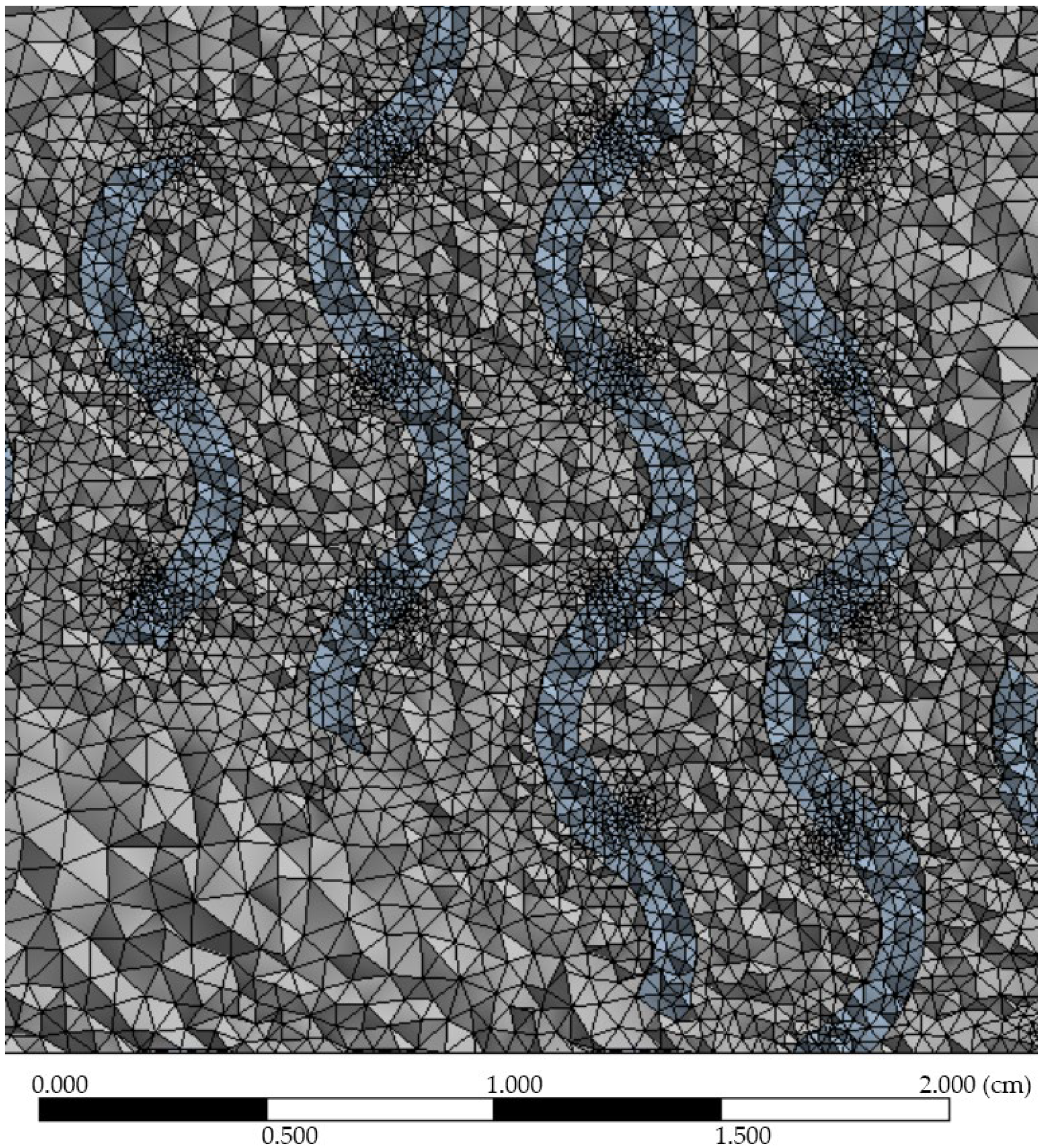
For numerical simulation and comparison purposes, volumes representing the flowing fluid were defined using this triplet of solids, which formed the basic element of the numerical simulation in Ansys Fluent 2020 R1 software. Given the need for flow steadiness prior to fluid entry into the three-dimensional structure, and to understand the emergence of turbulent regions after fluid exit from the three-dimensional structure, the resulting computational domain was designed to include a fluid flow at a distance of 20 mm prior to entry into the structure and 120 mm after fluid exit from the structure. The resulting objects representing the volume of the flowing fluid were transformed into a computational tetrahedral grid (see
Figure 4), while the area of the fluid inlet and fluid outlet of the computational domain were also defined.
Water was defined as the flow medium, with properties related to the temperature of 20 °C and flow velocity with values of 0.01, 0.025, 0.05, 0.075, 0.1, 0.25, and 0.5 m.s
−1 based on the intended use of the proposed structure in the heat storage unit of the internal combustion engine. The SST k-omega flow model was used to solve the numerical simulations, which was characterised by the robustness of the numerical model and the convergence of the results even for porous structures and low fluid flow velocities at the boundary of the laminar and turbulent flow [
31,
32,
33]. The calculation of the considered parameters in the form of pressure drop, flow velocity, or turbulent kinetic energy values was based on the Navier-Stokes system of equations describing the three-dimensional fluid flow and the Darcy–Weisbach equation, which quantifies the fluid friction, viscosity, density, and the associated pressure drop of the flowing fluid. The exact version of the mathematical model is available in the technical documentation of Ansys Fluent software (version 2020 R1) [
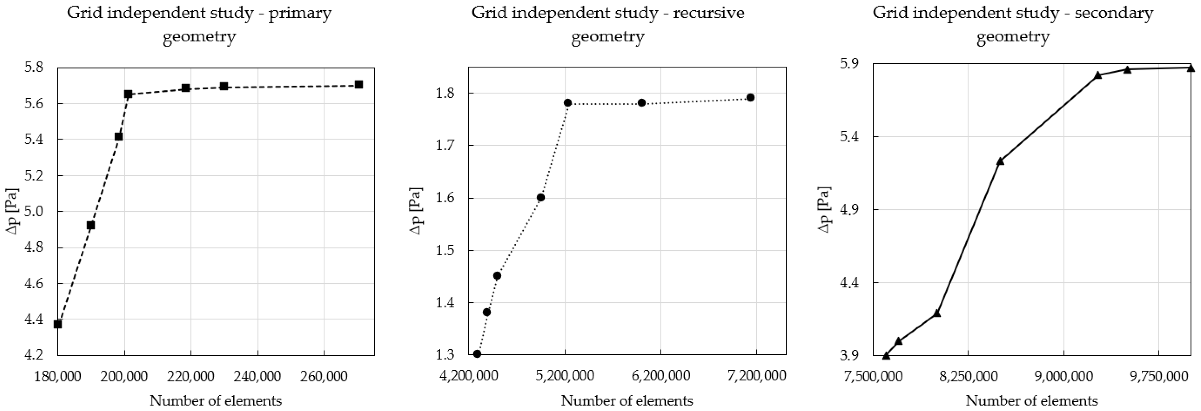
34]. The used geometric models or computational grids were subjected to a grid independent study before numerical simulation, which evaluates the influence of the quality of the computational grid on the resulting observed parameters of the numerical simulation. In the grid independent study, all three geometries were tested at the lowest flow velocity considered, while the change in the pressure drop value as a function of the change in the number of elements of the computational grid was monitored. The steady state of the observed parameter occurred when using a computational grid with approximately 220,000, 5,200,000, and 9,200,000 elements for the primary, recursive, and secondary gyroid geometries, respectively. The results of the grid independent study are summarised in
Figure 5, and the specific values of the computational grids used for each geometry are shown in
Table 1.
In terms of describing the influence of the three different structures on the fluid characteristics of the flowing medium, the pressure drop (Δp) and Fanning friction factor (fH) parameters were documented, respectively, calculated, and evaluated for the selected flow velocities (v) and associated Reynolds number (ReDh) values. The value of the pressure loss was determined by the pressure difference of the flowing medium upstream and downstream of the geometry under consideration, i.e., in the inlet and outlet planes. To visualise the influence of the structure on the formation of turbulent regions, sections with increased flow velocity, or locations with characteristic pressure reduction, the parameters turbulence kinetic energy (TKE), velocity, and pressure were monitored and visualised through contour map and volume rendering.
The Reynolds number based on the hydraulic diameter of the porous gyroid structure was calculated based on Equation (2) [
35].
where
Dh is the hydraulic diameter, characterising the size of channel that is open to the flowing medium, v is the flow velocity, and
ρ is the density of the flowing fluid. The
Dh parameter can be defined using various relations that relate the cross-sectional area of the channel and the wetted diameter. However, in the case of porous structures, as is the case of the gyroid structure presented here, the preferred approach is to calculate the hydraulic diameter using the porosity (
ϵ) and the specific surface area (
Ss) [
35]. Porosity is defined as the ratio of the volume of the voids (volume of channels open to flow) to the bulk volume of the structure (volume of the solid, which is characterised by the outer walls of the geometry, so, in this case, it is a cube with dimensions of 40 × 40 × 40 mm). The specific surface area is defined as the size of the wall area of the formed channels to the bulk volume of the structure. These geometric parameters were determined using Solidworks 2018 software allowing the analysis of the object’s surface area or volume. The
Dh parameter can then be defined as follows [
35].
The last monitored parameter is the Fanning friction factor (
fH), which characterises the dimensionless pressure loss or flow resistance in the channels of the gyroid structure and which is defined according to Equation (4) [
36].
where
Δp is the pressure drop,
L is the length of the three-dimensional geometric structure,
ϵ is the porosity of the structure,
Dh is the hydraulic diameter,
ρ is the density of the flowing medium, and
v is its velocity.
3. Results and Discussion
The effect of porous structures on the flow medium was analysed from the results of a numerical simulation involving a combination of three types of three-dimensional geo-metric solids and seven values of the working fluid flow velocity; thus, twenty-one cases covering the full range of expected working conditions of the proposed heat exchange element were used for comparison.
In particular, the possible negative effects of the proposed geometry on the fluid flow characteristics could be quantified by analysing the pressure drop data of the flow medium in the channel containing the porous structure. A reduction in the cross-sectional size of the channel through which the fluid can flow causes a change in the velocity parameters and associated changes in the fluid pressure. The increase in pressure or pressure loss of the flowing medium must then be taken into account in technical applications not only in the design of the hydraulic system in terms of its dimensions but especially in the design of the performance of the devices ensuring the circulation of the flowing medium.
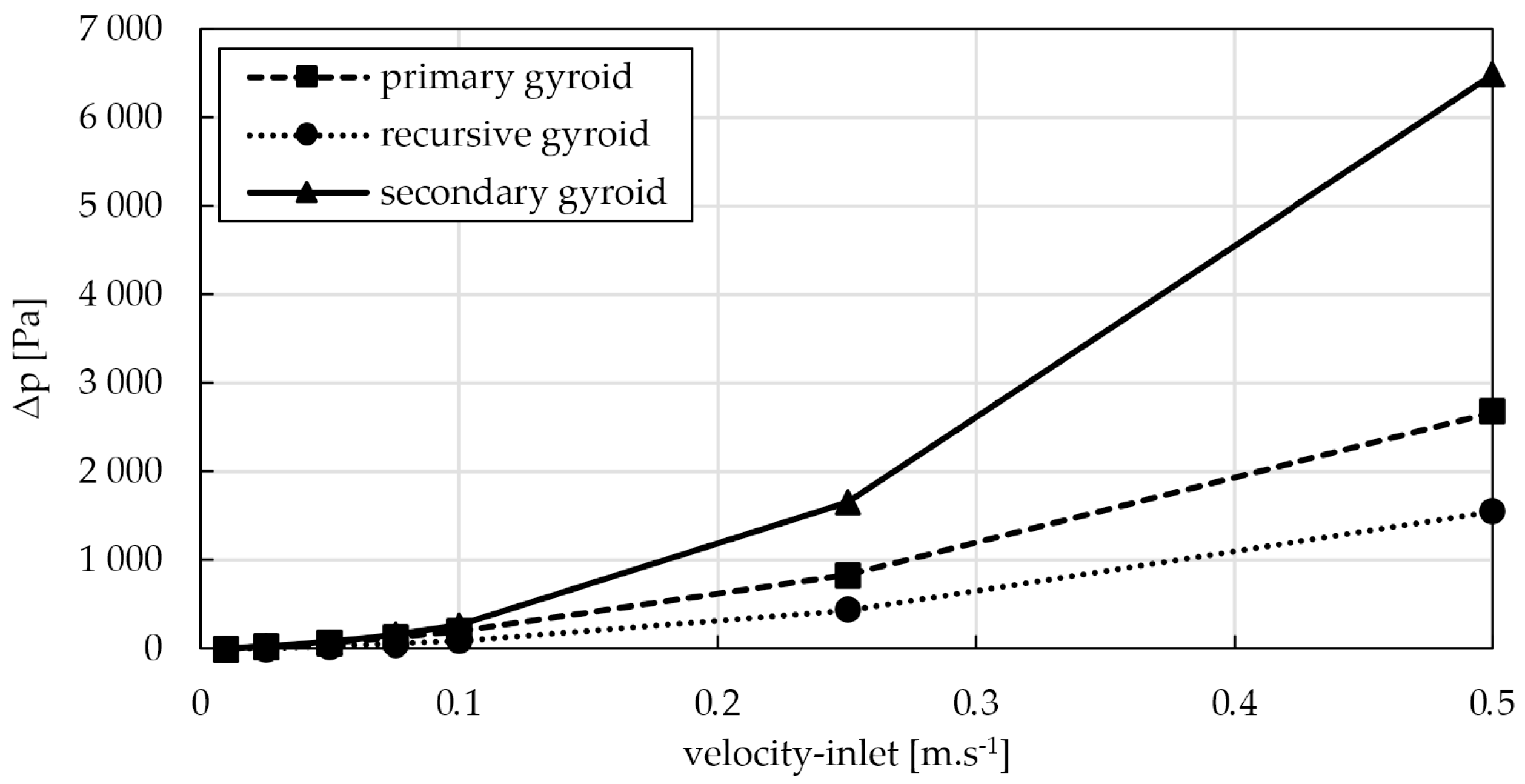
The specific pressure drop values are shown in
Figure 6. The graph shows the pressure drop results against the full range of media flow velocities used, ranging from 0.01 m.s
−1 to 0.5 m.s
−1. In terms of the overall assessment, it is evident that the largest pressure loss values are achieved by the secondary geometry, which is characterised by the smaller hydraulic diameter of the resulting channels, which, in the overall scale of the geometry, represent a significant obstacle reducing the effective channel cross-section, resulting in a maximum pressure loss value of 6 485 Pa for a flow velocity of 0. 5 m.s
−1, which is more than double the pressure loss values for the same flow velocity for the primary geometry and more than four times that of the recursive geometry proposed by the authors.
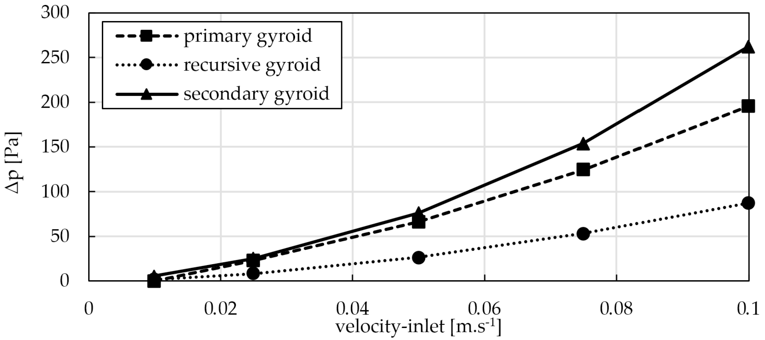
Due to the wide range of values of the resulting pressure loss of the flowing medium, ranging to thousands of Pascals, for better illustration, the pressure losses at lower flow velocities are shown in
Figure 7, where plots of the pressure losses up to a velocity of 0.1 m.s
−1 can be seen. In this display, which is focused, in terms of the numerical simulation performed on the lower flow velocity regions, the same trend can be seen, where the highest pressure loss parameters are achieved by the secondary structure, followed by the primary geometric structure, and the lowest pressure loss values are achieved by the recursive gyroid structure proposed by authors. The resulting pressure drop values in this region also indicate a partial balancing of the values for the primary and secondary structures and a slight rebound in the values of the recursive gyroid structure. The value of the pressure drop increases as the effective diameter of the flow channel decreases, which is related to the increase in total resistance due to the flow through the porous structure. The increase in pressure drop is accompanied not only by an increase in the flow velocity in the channels but also by an associated increase in friction. Thus, in the cases considered, these effects are most evident for the secondary geometry and least evident for the primary geometry. The numerical data are presented in
Table 2.
When comparing the effects of the geometry or changes in the selected device parameter on the overall fluid characteristics of the flowing medium, it is, in some cases, advantageous to compare the pressure losses against the Reynolds number values, which can be used to define whether the results presented are for a laminar, turbulent type of flow or for a transient laminar, turbulent flow regime.
Figure 8 shows the results of the pressure drop values presented against the Reynolds number for porous structures characterised by the hydraulic diameter described in Equations (2) and (3). When evaluating the Reynolds number for fluid flow in porous media, the region of laminar flow is up to the value of 10, and the region of turbulent flow is above the value of 200; then, between the values of 10 and 200, there is a transition region where we can speak of a combination of laminar and turbulent flow or a not fully developed turbulent flow [
37].
Taking a closer look at the Reynolds number values calculated from the input parameters of the individual geometries and the flow velocities used, it is evident that the numerical simulation covers a wide range of Reynolds numbers up to values characterising a highly turbulent flow. For a clearer display of the pressure drop values for low values,
Figure 8 is divided into two parts, where the right part shows the pressure drop values only up to the Reynolds number value at the 500 level.
From the results of the numerical analysis and with the use of the data correlation method, the relationship between the Reynolds number and the pressure drop for the considered cases can be written in the form of a power function. For the secondary geometry in the following form: Δ
p = 0.0094 Re
1.8034, R
2 = 0.9990; for the primary geometry in the form Δ
p = 0.0086 Re
1.564, R
2 = 0.9994; and for the recursive gyroid geometry proposed by the authors in the form Δ
p = 0.0013 Re
1.7265, R
2 = 0.9995. The numerical data are presented in
Table 3.
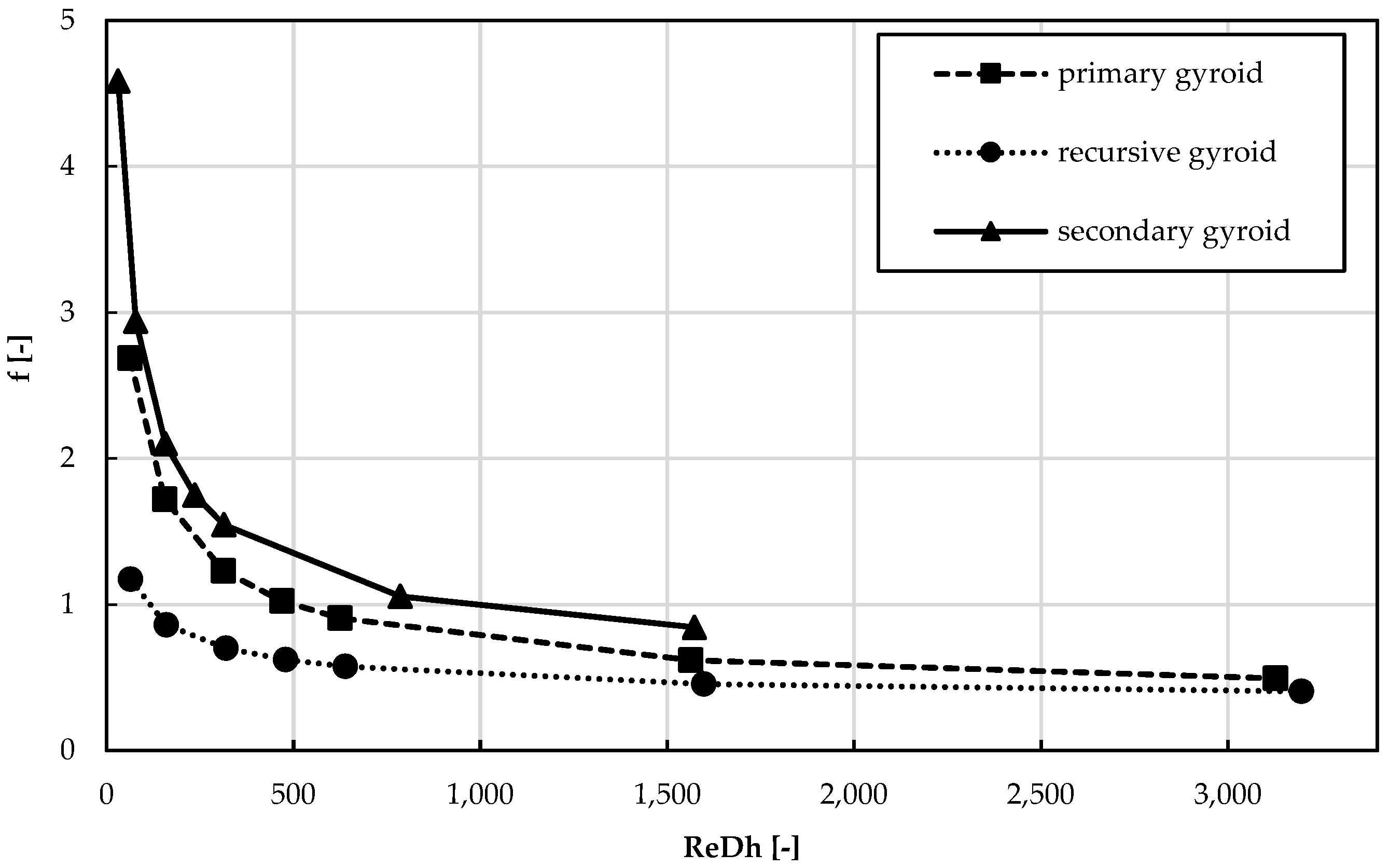
The last parameter investigated to characterise the effect of porous structures on the flow medium was the Fanning friction factor, which characterises the energy loss of the flow medium due to friction between the channel wall and the medium itself. Therefore, for the geometries studied, the channel wall was considered to be the surface defining the inner surface of the proposed gyroid structures. A graphical expression of the resulting values can be seen in
Figure 9, where the trend is confirmed, with the secondary geometry having the greatest negative influence on the flow, followed by the primary and, finally, the recursive gyroid geometry. The numerical data are presented in
Table 4.
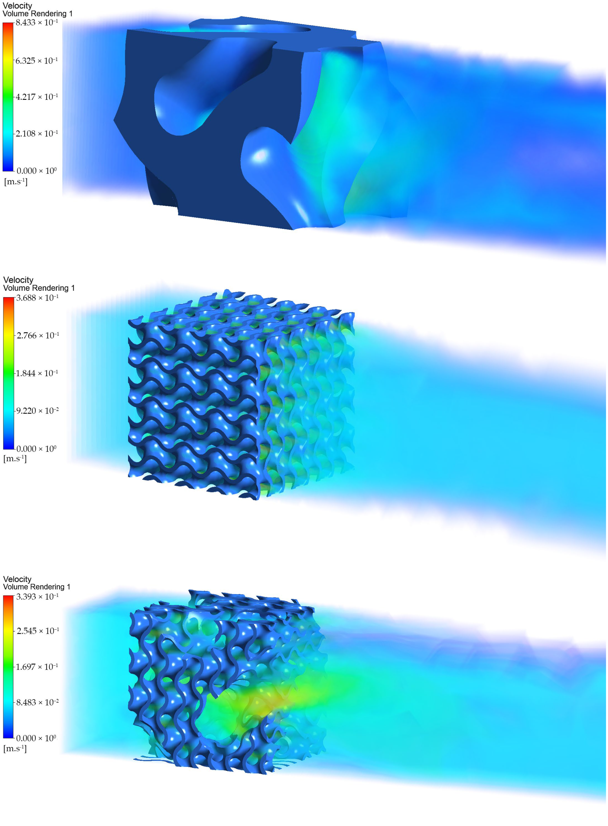
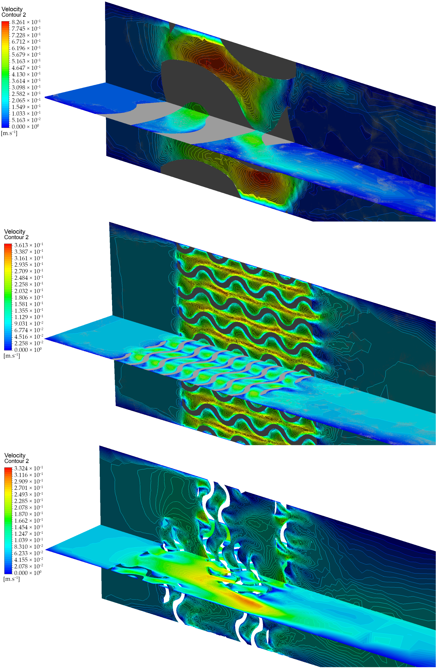
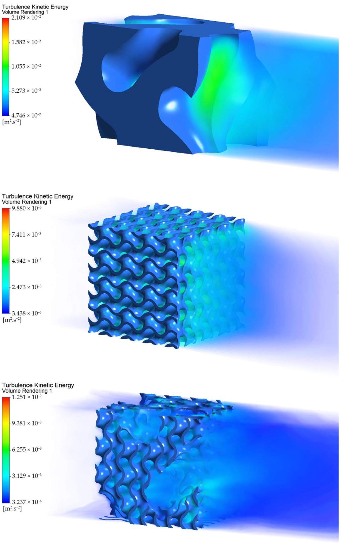
In addition to the outputs in the form of the presented data, the numerical simulation formed the basis for the visualisation of the selected flow parameters in two-dimensional, as well as three-dimensional, views for the creation of velocity and pressure maps, flow trajectory maps, and turbulent regions in channels affected by the considered geometric structures. For the sake of clarity of the presented paper, and due to the complexity or the amount of data of the compared variations of the combination of the flow velocity and types of geometrical structures, only the comparison of three geometrical structures at a mean velocity of 0.075 m.s
−1 will be graphically analysed in the text; however, the individual descriptions of the processes, as well as the conclusions, can also be applied to the comparison of geometries at other flow velocities. The results summarised in
Figure 10,
Figure 11 and
Figure 12 is generated by grouping the primary, secondary, and recursive geometries, respectively, and due to the significant differences in the values of the observed physical parameters, a separate scale of the displayed physical parameter is used for each geometry.
A basic idea of the three-dimensional nature of the flow of the medium through the compared structures can be obtained from
Figure 10, which shows all three structures in an isometric view, as well as a portion of the channel upstream and downstream of the structure. The flow velocities are visualised using volume rendering, showing the influence of the structure on the overall flow in the space occupied by the used geometries but also the downstream channel space in the direction of the medium flow, where the reaction of the fluid to the obstacle that is admittedly permeable on the one hand but, on the other hand, reduces the effective cross-sectional area of the channel is visible.
The fluid flow velocity parameter is also shown in
Figure 11, but in this case, a representation in two mutually perpendicular planes passing through the centre of the compared structures is used. In this case, however, the volumes of the compared geometric solids are no longer visible, being represented by the grey areas in the generated velocity maps. While, in the first case, for the primary geometry, there is a significant increase in the flow velocity in the gradually narrowing channel, for the secondary geometry, we see a steady but stepwise increase in the flow velocity through the entire uniform structure formed by the narrowed channels. For a recursive gyroid structure, a mutual combination of these processes can be identified, where both uniform flow through channels with smaller effective cross-sections and through channels with larger effective cross-sections is applied. This results not only in a reduction of the pressure loss but also in ensuring contact of the flowing medium with the maximum possible surface area of the geometric structure, which, in the case of its application as a heat exchanger element, will ensure a higher efficiency of the heat exchange process throughout the volume.
An equally important parameter describing the nature of the flow is the turbulence kinetic energy, which quantifies and describes the average kinetic energy per unit mass of the flowing medium. An increase in the value indicates the occurrence of eddy motions, which increases the mixing of the medium but also the friction between the fluid layers, leading to energy loss and pressure reduction. An increase in the value of the turbulent kinetic energy does not necessarily mean only a negative impact on the flow of the medium; in the field of the application of heat exchangers, the increased value of the turbulent kinetic energy helps the heat exchange process between the heat exchanger wall and the flowing fluid.
By analysing the flow of the medium, which is influenced by the recursive gyroid structure proposed by the authors, it is possible to identify quite interesting flow structures with different values of turbulent kinetic energy. Looking at
Figure 12, it can be seen at the bottom of the geometry the mutual influence of the flow by both the larger cross-section channel and, to a greater extent, by the more uniform smaller cross-section channels. The increased flow velocity in the main channel helps to magnify the flow, and the change in pressure acts on the flow trajectories in the uniform part of the geometry. On the outlet side of the geometry, the regions created by the combination of larger and smaller flow channels also cause turbulent regions to form, which aid in mixing the fluid even in the part where the flow medium is no longer in contact with the porous structure, again increasing the overall efficiency of the heat exchange process of the device.
The numerical simulation results showed a reduction in the negative impacts on the fluid flow characteristics of the flow medium when using the proposed recursive gyroid geometry compared to conventional geometries based on triply periodic minimal surfaces. However, this needs to be anchored in a broader context, including other parameters affecting the heat transfer process. As it has been mentioned several times in the presented text, one of the key parameters is the size of the heat exchange surface or the value of the specific surface area, which relates the heat exchange surface and the bulk volume of the element. These values for the three geometries considered are summarised in
Table 5.
The largest heat exchange surface is the secondary geometry, which is characterised by a uniform channel structure with a small value of the effective cross-sectional area of the channels. Compared to the proposed geometry, it is more than 50% larger, which represents a non-negligible influence on the efficiency of the heat exchange process. Compared to the primary geometry, the proposed recursive geometry has a 160% larger heat transfer area but with a substantial reduction in the negative impact on the fluid characteristics.
The use of geometric objects based on triply periodic minimal surfaces in industrial applications has been a significant challenge until recently, particularly in terms of the manufacturability of complex three-dimensional structures. These challenges were exacerbated when attempting to create such structures from metals or thermally conductive materials in general. Only significant technological advancements in additive manufacturing have enabled not only broader possibilities in the scientific research of triply periodic minimal surfaces but also their actual deployment in technologies involving heat exchangers, radiators, or thermal accumulators.
Gabrieli et al. [
20] addressed 3D printing using stereolithographic techniques to create triply periodic minimal surfaces in the form of Schwarz P and gyroid. Although the authors did not use thermally conductive material, the methods employed yielded highly accurate products. Zhao et al. [
18], in their study on media flow and heat exchange processes using 3D printing, created an octahedral lattice frame of porous material from aluminium alloy (AlSi
10Mg). Choong et al. [
38] provided an overview of possibilities for creating lattice structures from a highly thermally conductive material, copper, using various methods based on laser-based powder bed fusion. Anwajler et al. [
39] focused on the use of specific additive manufacturing technologies such as SLA (laser beam curing resin printing) and SLS (laser sintering of powdered plastics) in the process of creating triply periodic minimal surfaces objects and examining their thermal properties.
The range of complexity of 3D printing techniques is significant, and despite substantial technical progress, individual technologies are not automatically accessible to scientific or development teams in various parts of the world. One way to create these shape-complex objects is by using the so-called FFF/FDM methods of 3D printing (Fused Filament Fabrication/Fused Deposition Modelling). However, a fundamental issue in this case is the low availability of thermally conductive materials suitable for this printing method, as well as their thermodynamic parameter values, such as thermal conductivity and thermal capacity. One promising direction of research in the field of FFF/FDM methods is the utilisation of high thermal conductivity polymer composites, which employ high loadings (>25 wt%) of thermally conductive carbon fibres, carbon powder, ceramics, heat conducting nanomaterials, and other thermally conductive fillers to enhance thermal conductivity in thermoplastic composite materials [
40]. The other disadvantage of FFF/FDM 3D printing is the creation of a three-dimensional object by gradually building up thin layers of material. This fact results in different properties of the resulting object depending on the direction of physical processes (such as tension, pressure, direction of heat flow, etc.). This fact must be taken into account both in the design of the object itself and in its orientation relative to the printing plane during the 3D printing preparation process.
While this method of 3D printing and materials may not achieve the thermal conductivity values obtained with metals and alloys, their widespread economic availability enables the production of heat exchangers with complex geometric parameters of triply periodic minimal surfaces in areas where metallic heat exchange elements have been traditionally used, albeit with simpler geometries featuring simple plates or fins. When utilising 3D-printed heat exchangers made from thermoplastic polymers with lower thermal conductivity, their more complex geometric structure can compensate for the lower thermal conductivity values and paradoxically enhance the effectiveness of the heat exchange process.
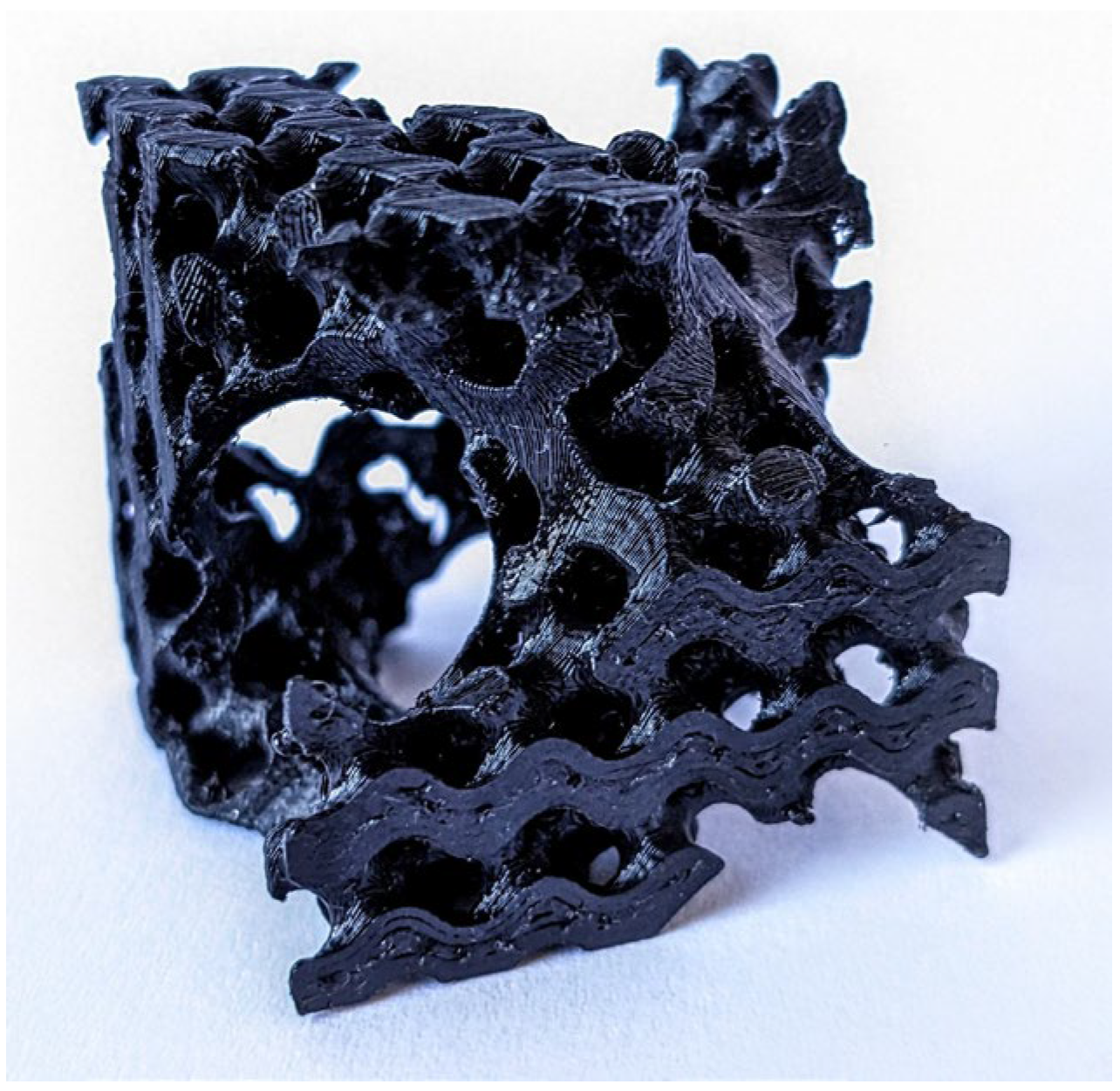
The above-mentioned methods and materials were used to create a sample of the recursively designed gyroid geometric structure proposed by the authors, which is depicted in
Figure 13. A commercially available FFF/FDM 3D printer, Prusa MK3S (manufacturer Prusa, Prague, Czech Republic), with a 0.8 mm extruder was used for printing, along with a thermally conductive filament from the company TC-Poly, which achieves a thermal conductivity value of 6 W.m
−1.K
−1 in the printing plane.
The resulting object accurately replicates the intended recursive gyroid structure. However, a closer examination reveals deformations in the wall quality, potentially leading to increased friction. Eliminating these microscopic wall irregularities can be achieved by fine-tuning the printing parameters. This may involve adjusting the extruder temperature, print bed temperature, or the ambient environment within the printer. Additionally, modifications to the filament flow through the printing nozzle or the speed of the print head during individual layer creation could be explored. In general, it can be concluded that the fabrication of complex geometries of triply periodic minimal surfaces from thermally conductive materials using available FFF/FDM 3D printers is feasible, and the authors anticipate that their use in the creation of heat exchange elements of heat exchangers will increase in the future.
4. Conclusions
Increasing the heat exchange surface area is an important element in improving the efficiency of the heat exchange process of equipment such as heat exchangers or heat accumulators. In the presented paper, a geometrical structure has been proposed which geometry combines two specific approaches to the formation of a three-dimensional solid—triply periodic minimal surfaces and a recursive function. The result is a gyroid structure replicating the geometrical parameters forming the basic surface of the heat exchange element. The main objective of the presented study was to map the influence of the porous structure thus formed on the flowing medium, while the values of pressure drop and friction coefficient, as well as changes in the velocity, pressure, and turbulent kinetic energy, were monitored at flow rates simulating the intended use of the heat exchange element in the heat accumulator of an internal combustion engine. The numerical simulation results in Ansys Fluent 2020 R1 software demonstrated a reduction in the negative impact of the authors’ proposed structure on the flow medium compared to other geometries that are also gyro-based but do not use a recursive approach to geometry creation. Based on the visualisation of the values of the working medium flow velocities, or values of its turbulent kinetic energy, it is also possible to point out the increased ability to mix the working medium in the channel downstream of the heat exchanger element, which also helps to increase the heat flux from the heat exchanger element to the working medium.
The presented idea of utilising a gyroid recursive structure stems from an ongoing pursuit of maximising heat exchange processes by increasing the heat exchange surface area of the device while simultaneously maintaining its outer dimensions, thus increasing the ratio of the specific heat exchange surface area to the bulk volume. Addressing this issue requires considering a series of technical obstacles arising from the geometric essence of the heat exchanger itself, which directly influence the operational parameters. The results presented in this study are applicable in seeking the optimal geometry to eliminate the negative consequences of pressure loss increase in the device or to maximise the mixing of the heat transfer medium in a wide range of heat exchange devices. The achieved results quantify specific values of pressure loss and highlight fundamental differences in the flow characteristics of the various assessed structures, clearly indicating the structure with the greatest potential for use in thermal engineering.
The analysis and results of the fluid characteristics, or the influence of the proposed structure on the flow medium, pointed to the applicability of this geometry in further research, which, in this case, will already be focused on the thermodynamic properties of the geometry and the quantification of selected characteristics of the heat exchange process, both in the form of numerical simulations, as well as in the form of prototype production and physical measurements using an experimental measuring apparatus.
An important factor in the conception of the presented three-dimensional geometrical element was also the condition of necessity of its manufacturability by widely available means of additive manufacturing, which was verified in the production of the sample geometry from thermally conductive printing material. According to the authors, the presented geometry of the heat exchange element represents not only an interesting research area in the future, from the point of view of investigating thermodynamic parameters, but also an application area for a wide range of technologies.


