Article

Hybrid Z-Source Circuit Breaker with Thomson Coil for MVDC

1
Department of Social Safety System Engineering, Hankyoung National University, 327 Chungang-ro, Anseong-si 17579, Gyeonggi-do, Republic of Korea
2
Department of Electrical Engineering, Bucheon University, 25 Sinheung-ro, 56 Beon-gil, Buchen-si 14632, Gyeonggi-do, Republic of Korea
3
School of Social Safety System Engineering, Research Center for Safety and Health, Hankyoung National University, 327 Chungang-ro, Anseong-si 17579, Gyeonggi-do, Republic of Korea
*
Authors to whom correspondence should be addressed.
Energies 2024, 17(1), 69; https://doi.org/10.3390/en17010069
Submission received: 23 November 2023 / Revised: 15 December 2023 / Accepted: 19 December 2023 / Published: 21 December 2023
(This article belongs to the Section F: Electrical Engineering)

Abstract

:
Hybrid circuit breakers are the most promising circuit breakers among DC circuit breakers. Conventional hybrid circuit breakers complete fault current isolation by converting current to IGBT when fault current occurs. However, in this case, the fault current continues to increase, so the IGBT must be large enough to withstand this current. In addition, in the case of a method of detecting and operating a fault, a delay time of up to hundreds of microseconds occurs, and in a hybrid circuit breaker, this delay time is a very large value. To solve this problem, this paper proposes a hybrid Z-source circuit breaker that operates without delay for low-impedance faults. The proposed breaker is designed to reduce stress on IGBTs and mechanical switches by generating a current zero crossing, as well as to enable the breaker to trip quickly in high-risk cases such as low-impedance fault circuits. Due to the limited environment of the laboratory, we performed 600 V fault isolation experiments. As a result of the experiment, it was confirmed that the proposed circuit breaker successfully isolated the fault within 1.6 ms. The current limiting feature of the Z-source appears to reduce stress on the IGBTs and MOVs used, and it allows for faster fault isolation.

1. Introduction

Medium voltage direct current (MVDC) has various advantages such as flexibility, controllability, high power quality, and large transmission capacity [1,2]. However, when a fault occurs, direct current causes the fault current to rise rapidly [3,4]. Failure to isolate and eliminate faults quickly can result in damage to critical components, such as power converters used in the grid. Also, because the power distribution system has several lines connected, even lines that are not faulty can be affected. Therefore, it is very important to contain the fault current and clear the fault quickly.
Typically, there are three types of DC breakers [5,6,7]: mechanical switch circuit breakers (MCB) [8,9], semiconductor switch circuit breakers (SSCB) [10,11,12], and hybrid circuit breakers (HCB) [13,14,15,16,17]. The MCB is composed of a pure mechanical switch, with low loss and large breaking capacity, but with low speed. The SSCB is capable of arc-free fault isolation and is fast but has large normal state losses, and semiconductors require a large number of serial and parallel configurations. The HCB is a circuit breaker that increases the fault isolation speed by using a mechanical switch with low loss in normal state and a fast semiconductor switch in fault isolation.
Among them, Z-source topology is proposed as a SSCB [18,19,20,21,22,23,24]. A Z-source network consisting of an inductor and a capacitor is used to create a current zero-crossing in a switch from direct current with no current zero-crossing. SCR is naturally turned off at current zero crossing to isolate a fault current. A mechanical switch Z-source circuit breaker was proposed to increase the efficiency of the circuit breaker and to control on/off control by the user [25]. This circuit breaker uses a Thomson coil actuator (TCA), which is a high-speed switch. In addition, a model that improves fault isolation speed and actively operates in low-impedance fault circuits is proposed. In this model, a Thomson coil is put into a circuit, and when a low-impedance fault occurs and a high current flows, the TCA operates immediately without a driving circuit [26]. However, a problem that still exists is the limit of the fault isolation rate due to the arc generated at the contact point.
The arc generated at the breaker contact will extinguish spontaneously as the arc cannot be maintained near the current zero point. However, the arc may not be extinguished even after the current zero-crossing point, and the breaker contacts will be damaged until the arc is extinguished. As a result, it shortens the life of the breaker. Even if the arc is turned off, a re-ignition phenomenon may occur depending on the insulation recovery time between the circuit breaker contacts and the applied voltage immediately after fault isolation. Re-ignition is a phenomenon in which insulation is destroyed and energized when a voltage higher than the dielectric recovery voltage of the circuit breaker is applied, which means fault isolation failure. Hybrid circuit breakers have been introduced to address these issues. Hybrid circuit breakers are capable of isolating faults without arcing, minimizing, or eliminating the arcing generated by mechanical switch contacts. Hybrid circuit breakers increase efficiency by using mechanical switches with low power loss in a steady state. When a fault occurs, the contacts of the mechanical switch separate and the resistance increases accordingly, allowing the fault current to flow into the relatively low resistance IGBT. When the IGBT turns off after the current has fully switched, the remaining energy is absorbed by nonlinear elements such as varistors or thermistors to isolate the fault. However, this method increases the number and cost of the IGBTs due to the high current that the IGBTs must sustain in the case of failure. In addition, as the IGBT cut-off current increases, a metal oxide varistor (MOV) must absorb a large amount of energy, increasing the volume, capacity, and cost of the MOV.
In order to solve the aforementioned problem, this paper proposes a new hybrid Z-source circuit breaker (HZCB) model. This creates a forced current zero crossing across the switch through the Z-network. Similar to the fault isolation method of a mechanical switch, the IGBT is also turned off when the current is near 0 or the current decreases, so the current that the IGBT and MOV can handle is reduced compared to the existing hybrid method. This approach speeds up the breakers and reduces the stress on IGBTs and MOVs. The main contributions of the paper are as follows:
  • A new bi-directional hybrid DC circuit breaker topology.
  • No or minimal arc operation.
  • High reliability through fault isolation at current zero crossing.
  • Fast fault detection in low impedance fault.
  • IGBT, MOV stress, and size reduction.
This paper is organized as follows. Section 2 describes the operating process of the proposed HZCB. The design and simulation results of the TCA to improve the circuit breaker speed are presented in Section 3. Section 4 empirically evaluates what has been said in Section 2 and Section 3. Finally, Section 5 is the conclusion.

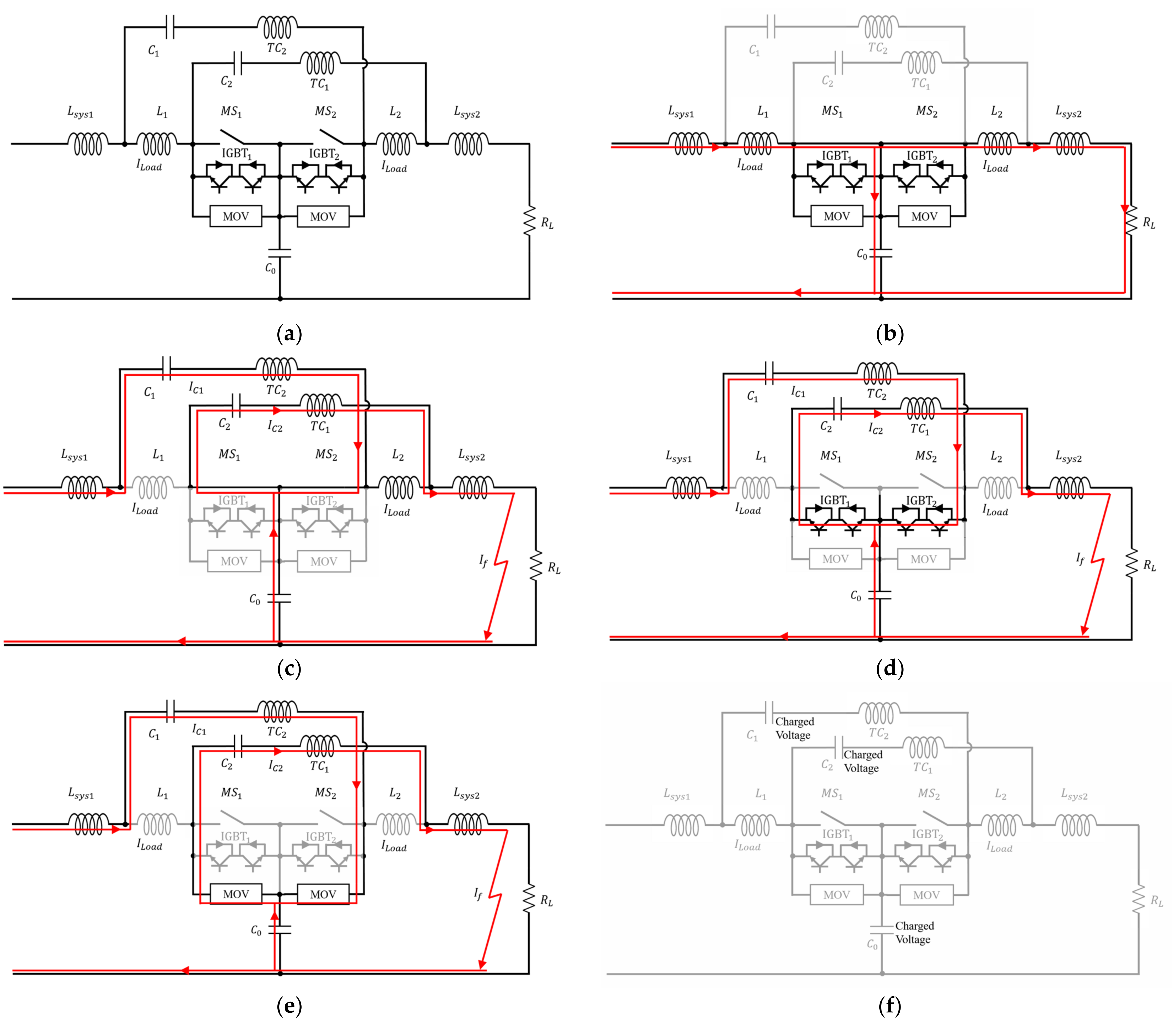
2. Proposed Hybrid Z-Source Circuit Breaker

The proposed topology of the DC circuit breaker is shown in Figure 1a, which is composed of a TCA (MS1, MS2), system inductor (Lsys1, Lsys2), opening Thomson coil (TC1, TC2), impedance network inductor (L1, L2), impedance network capacitor (C0, C1, C2), IGBTs, and MOV. The proposed hybrid circuit breaker is designed so that MS1 acts as the main circuit breaker in case of a fault on the load side and MS2 acts as a main circuit breaker in case of a fault in the power supply side. Through this double fault isolation structure, the circuit breaker is designed to complete its operation more safely, and through this, it can be equipped with high reliability.

2.1. Operating Principle

The proposed HZCB is shown in Figure 1b in normal conduction mode. In DC, consider the inductance as a fault circuit and the capacitor as an open circuit, and use a high-efficiency mechanical switch. When the breaker is first applied to the circuit, C0 is charged with the power supply voltage and maintains the power supply voltage thereafter. At this time, the current flow is LSYS1-L1-MS1-MS2-L2-LSYS2-RL.
When a fault occurs, the circuit breaker current flow is as shown in Figure 1c. Due to load fluctuations under fault conditions, direct current has a frequency like alternating current. According to Equation (1), the inductor L suppresses the rise of the fault current by increasing the impedance, and the capacitor has a low impedance, so the current flows through the capacitor path. At this time, a current is applied to the Thomson coil, and the MS starts to separate its contacts. At the same time, the fault current causes LC resonance of LSYS and C. That current and the discharge current of C0 flow through the switch in the reverse direction of the load current, and the switch experiences a forced current zero crossing. Current zero crossings can be created twice or more. After the first current zero crossing, the MS has a high resistance because the contacts are separated. If the IGBT is operated at this timing, current flows through the IGBT as shown in Figure 1d. Then, when the IGBT is turned off, current flows into the MOV as shown in Figure 1e. MOV prevents burnout due to the overvoltage of IGBT and safely isolates DC faults by consuming the remaining energy. After fault isolation, the impedance network capacitor is charged with the supply voltage. This voltage can be a problem when re-closing the breaker. Therefore, it must be re-closed after discharging through a resistor or other device at re-closing.
Figure 2 is the fault current waveform flowing through the switch of the proposed HZCB. When a fault occurs at t0, the current flows in the path of Figure 1c. Current flows through the switch in the opposite direction to the load current. When IC2 = ILOAD, the first current zero point t1 is created. The drive Thomson coil that operates the TCA is put into the circuit, so when there is a low impedance fault, the current flows and operates. When the force of the magnetic field of the Thomson coil exceeds a certain value, the pushing force of the magnetic field is greater than the force of the spring. Therefore, at t2, the contact is disconnected, and at t3, the IGBT operates. At this time, the current flow is shown in Figure 1d. At t4, when the IGBT is turned off, the current becomes zero, and the MOV absorbs energy. At this time, the second current zero crossing point is t5, and the current flow is as shown in Figure 1e.
Since the Z-source topology creates a current zero crossing in the breaker switch, it is possible to avoid the problem that the MOV absorbs a lot of energy due to the IGBT breaking at a large current. Since the MOV absorbs less energy than before, not only does the breaking speed decrease, but also the volume and capacity may decrease. The breaking speed reduction is detailed in Section 2.3.

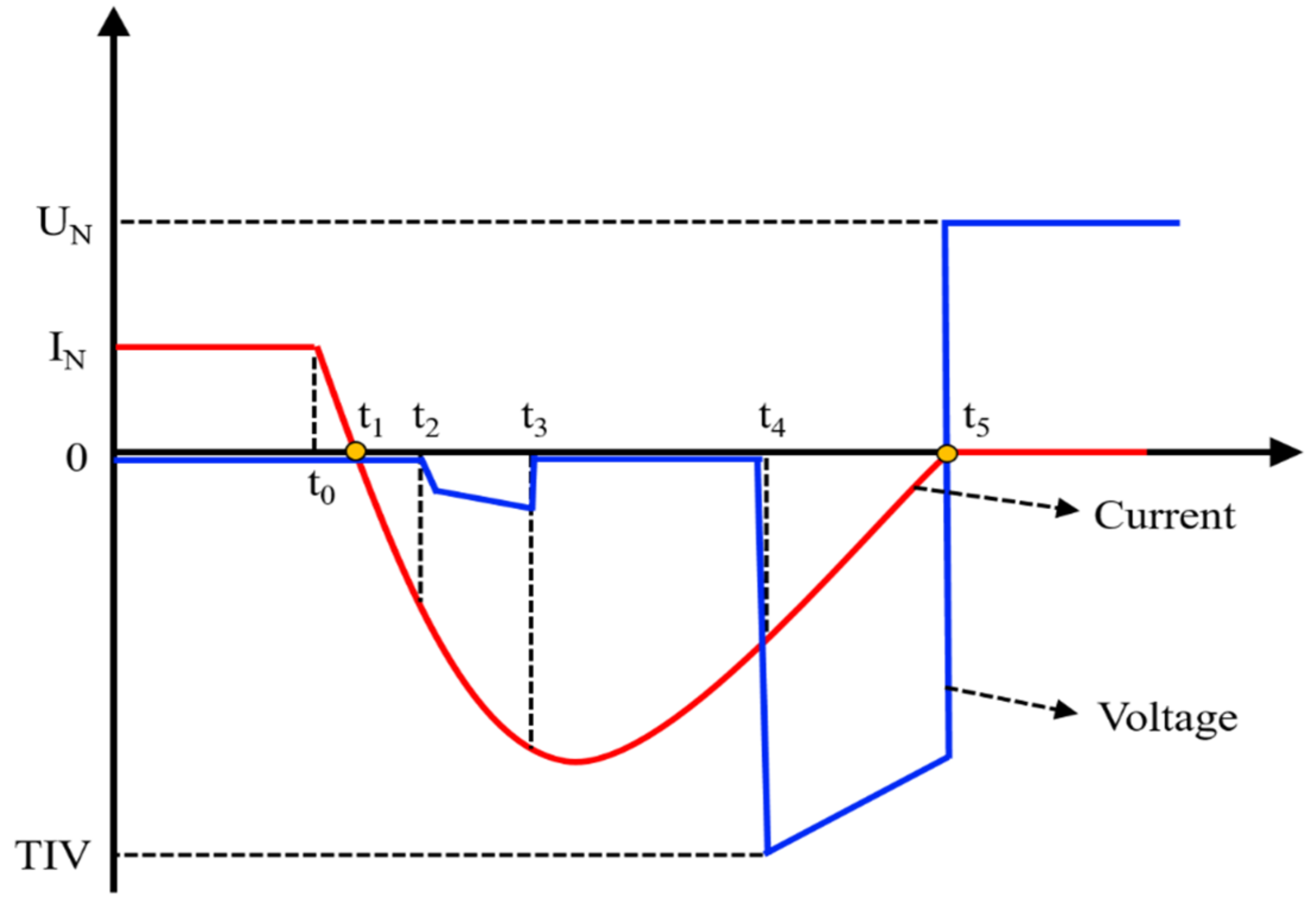
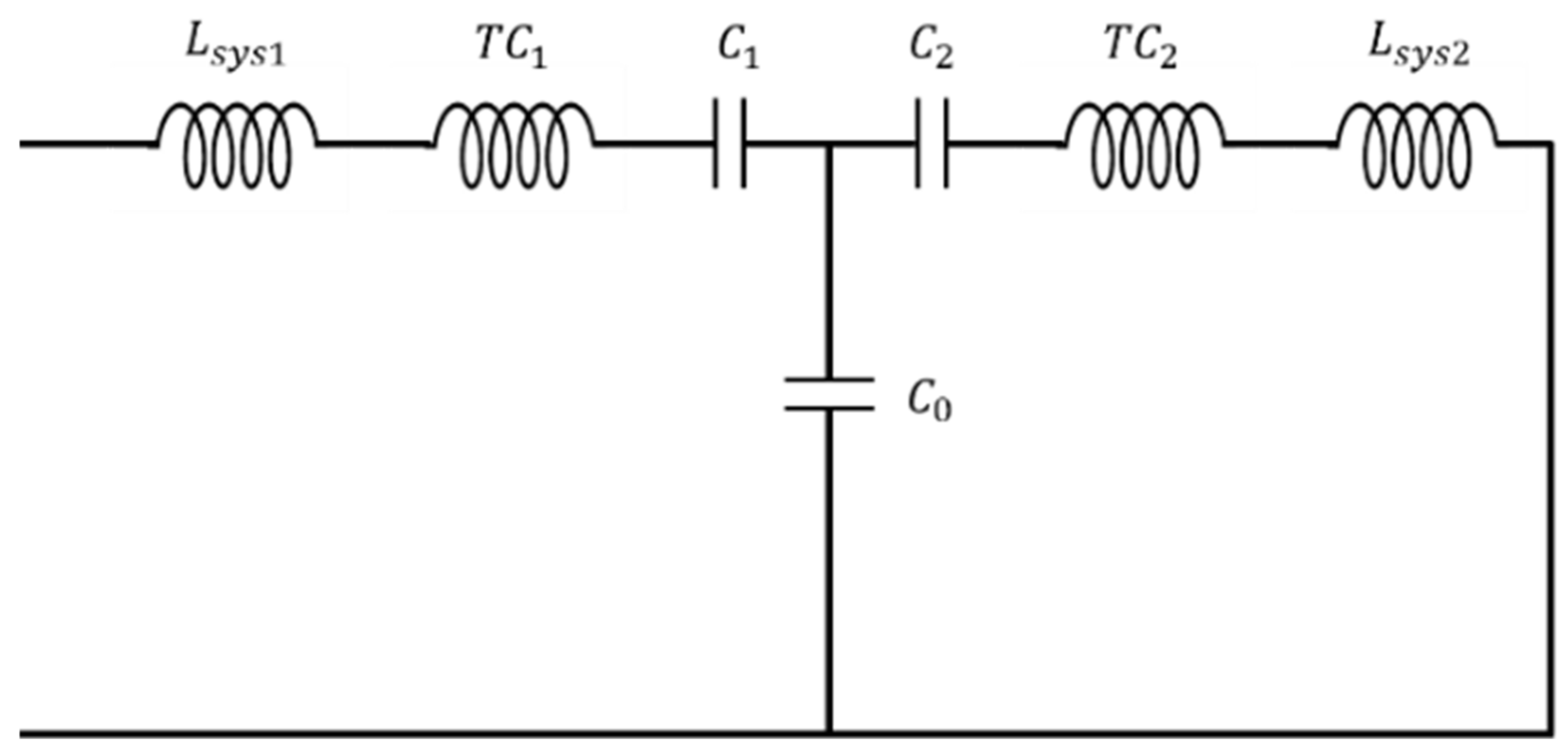
2.2. Current Zero Crossing Time

The current zero crossing time design in fault isolation is expressed mathematically. When the circuit shown in Figure 1 fails, the equivalent circuit is as shown in Figure 3. Assume that C0 = C1 = C2 = C, LSYS = L, and TC is very low and does not affect the circuit.
At this time, if the circuit is analyzed through Kirchhoff’s law and Laplace transform, the current flowing through C1 and C2 is as follows:
I C 1 = V S C 4 L sin t LC 1 3 sin 3 LC t I C 2 = V S C 4 L sin t LC + 1 3 sin 3 LC t
where IC2 is the sum of the discharge currents of C0 and fault current IC1.
This current makes a current zero crossing on MS1. When the current flowing through the IMS is 0, it experiences zero current crossing, so it is as follows:
I M S = I L o a d I C 2 0 = I L o a d I C 2 I L o a d = I C 2
I Load = V S C 4 L sin t LC + 1 3 sin 3 LC t
The current zero crossing times t1 and t5 derived using Equation (3) are as follows:
t 1 = LC 4 sin 1 L C × I Load V S + LC 12 sin 1 3 L C × I Load V S
t 5 = LC 4 π - sin 1 L C × I Load V S + LC 12 π - sin 1 3 L C × I Load V S
The above time t5 assumes that the magnetic field of the impedance network inductor is maintained without collapsing according to the equivalent circuit. In practice, however, this value must be taken into account because the magnetic field of the impedance network inductors L1 and L2 collapses during the transient period. Therefore, the time of t5 changes and can be expressed as the ratio of the inductor as follows:
t 5 = t 5 × 1 L SYS L All
t 5 = LC 4 π - sin 1 L C × I Load V S + LC 12 π - sin 1 3 L C × I Load V S

2.3. Breaking Time

If only MS is used for fault isolation, the fault current is isolated at t5. However, in HZCB, the IGBT isolates the fault current faster than the current zero crossing point. After the IGBT is turned off, the current of the MOV is rapidly reduced and the fault current isolation is completed faster than the time of t5. Therefore, the total fault isolation time is as follows:
t all = t MS + t IGBT + t MOV = t 4 + t MOV
where tMS is the operating time of the mechanical switch, tIGBT is the operating time of the IGBT, and tMOV is the energy absorption time of the MOV until the IGBT turns off and the current becomes zero.
MS and IGBT satisfy the existing Equations (1)–(8), but MOV is closely related to the current, power supply voltage, and system inductance when the IGBT is turned off. Therefore, as proposed by Peng’s research team, it can be expressed as a value considering the system inductance and current [27]:
t mov = L S × i V C V S
where LS is system inductance, i is current at IGBT turn off, VC is clamping voltage, and VS is source voltage.

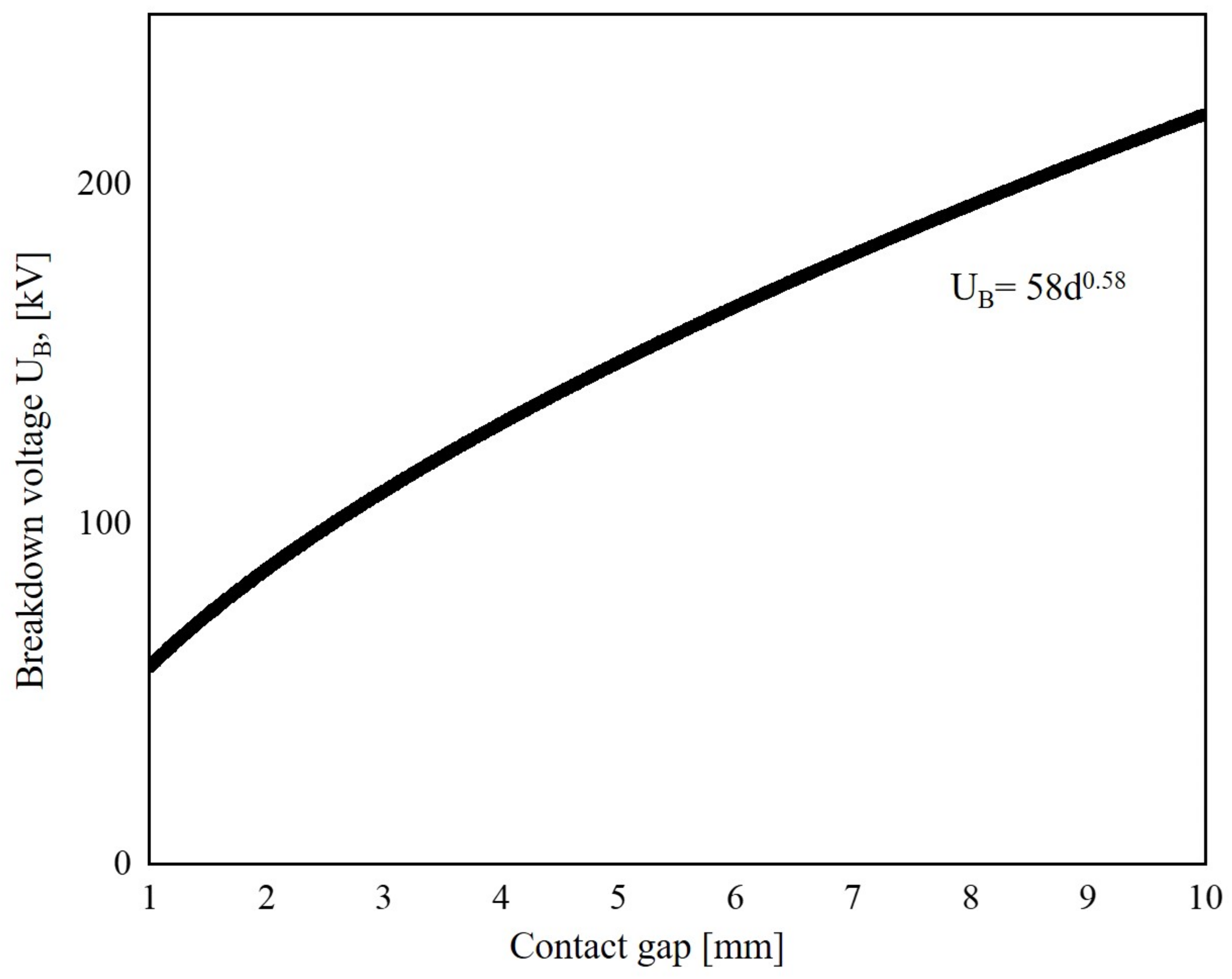
2.4. Prevention of Re-Ignition and Insulation Breakdown

The IGBT should be turned off after the contacts of the MS are wide enough and insulation is restored. If this is not done, insulation breakdown or re-ignition may occur. The minimum time to turn off the IGBT according to the power supply voltage and the insulation strength of the vacuum so that the insulation of the vacuum interrupter is not destroyed can be obtained using the graph below and the breakdown formula. Looking at the curve of dielectric strength in vacuum, the dielectric breakdown voltage between 1 mm and 10 mm is as shown in Figure 4 [28].
In addition, the re-ignition phenomenon of the circuit breaker may occur due to a recovery voltage greater than the dielectric strength. However, in the case of the hybrid method, fault isolation with almost no arc is possible, so only a certain amount of time was secured through the dielectric breakdown formula, and no other analysis was conducted.

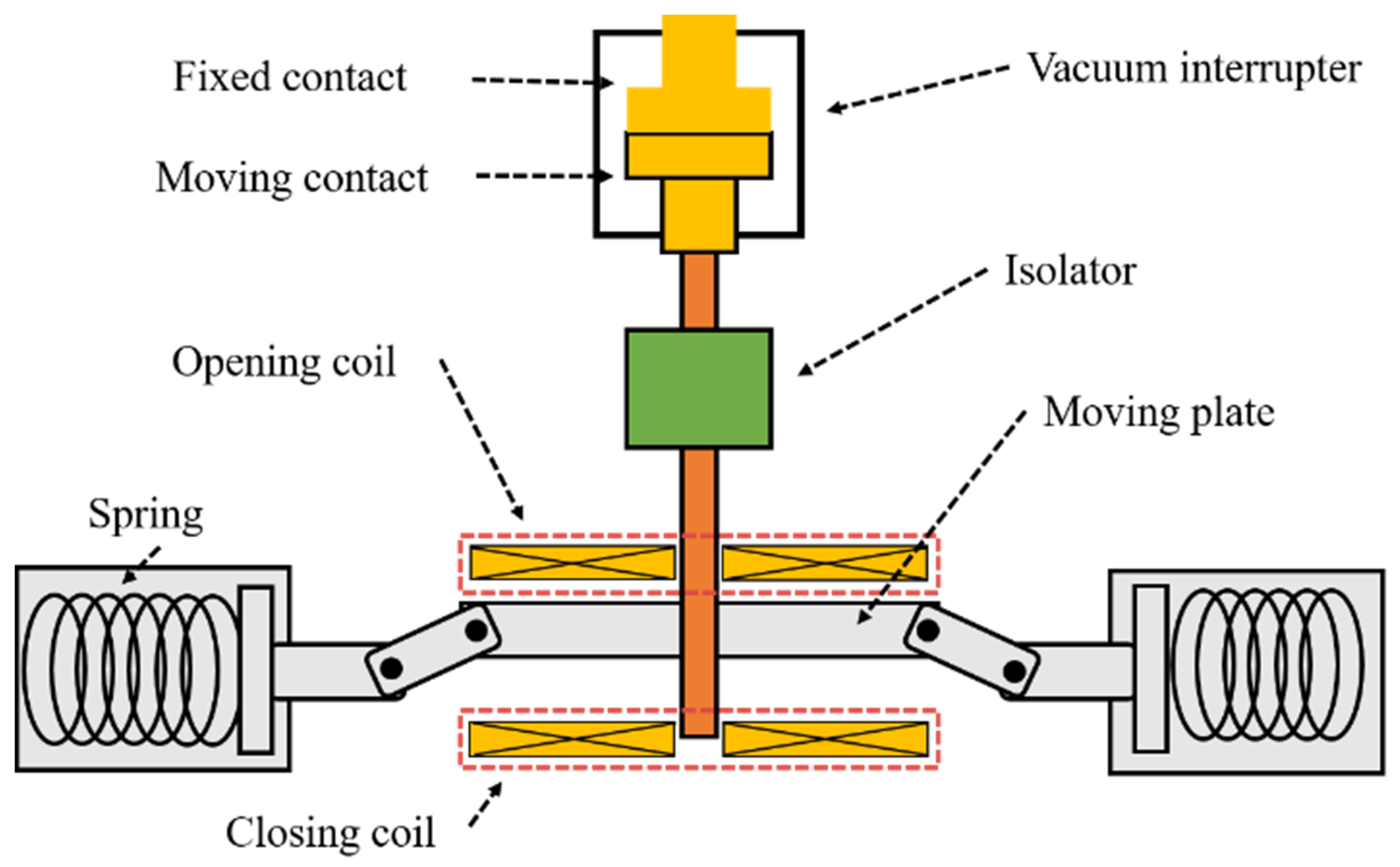
3. Thomson Coil Actuator Operation Design

3.1. Thomson Coil Actuator Overview and Construction

TCA is an ultra-fast switch, and it is used in hybrid circuit breakers and various applications [29,30,31,32,33]. A Thomson coil has a spiral shape and operates by flowing a pulse current of several kA through a capacitor bank. When a large current is momentarily applied to the coil, a large repulsive force is generated between the coil and the moving plate. Through this force, the contact of the vacuum interrupter connected to the moving plate is quickly separated. The components of TCA are as follows: a vacuum interrupter that isolates the fault current, a Thomson coil (opening coil and closing coil) that gives power to move the moving plate through current flow, a spring that fixes the position of the contact point, and an isolator that insulates the current flowing in VI and the Thomson coil. The configuration used in the white paper is shown in Figure 5. Several papers say that Thomson coils have a delay until they operate [27]. Therefore, in this white paper, a model in which a Thomson coil is put into the circuit was adopted to minimize this time. In this model, the current flows into the Thomson coil as soon as a fault occurs, minimizing the delay time. In this section, several designs are presented so that the TCA can operate only with high-fault currents such as low-impedance fault.

3.2. Finite Element Modeling and Operating

The force acting on the operation of the TCA should consider various physical factors. Therefore, it was designed using the finite element method (FEM) of multi-physics simulation. The simulation was conducted using the materials of the COMSOL program 5.6, magnetic field, dynamic mesh, electric circuit, magnetic field, and mesh. The Thomson coil used ideal copper as a material; aluminum was selected as the moving disk, and vacuum was selected as the surrounding atmosphere. The force of the magnetic field and the speed of the moving disk generated when current flows from the coil were derived using the coil, Lorentz force, and electric circuit of the magnetic field item.
The fault current provided by the Z-source topology in the system with the power supply voltage in Table 1 is shown in Figure 6 according to Equation (1).
At this time, the Thomson coil actuator should be selected so that it can operate only in threatening fault circuits such as low impedance. The load of the spring that plays the role of fixing the TCA can be calculated with the basic spring force formula. In order to design this value to operate only when the low impedance fault occurs, force, gravity, and self-closing force of the contact must all be considered when current flows in the Thomson coil. When the current in Figure 6 flows through the TC, the force was derived through FEM analysis. At this time, the simulation result was as shown in Figure 7.
The force pushing the plate is composed of Fg (gravity) + Fe (electromagnetic force)—Fcs (contact shielding force)—Fs (spring force), and it must be set not to operate at a force smaller than this value. The contact self-closing force of the vacuum interrupter used is 157 N, and the force due to gravity is negligible due to the contact self-closing force. At this time, since the spring load must be large enough to withstand the contact self-closing force, the spring force must be greater than the contact self-closing force. The force pushing the plate is Fe-Fs, and a force large enough to overcome the enduring force of the spring must be applied to the moving plate. As a result of FEM analysis, the speed and distance of the moving plate are as shown in Figure 8.
When the current shown in Figure 6 flows through the Thomson coil actuator, the contact moves 15 mm within 2 ms. The current in Figure 6 is designed to be similar to the fault current when a device using a 10 kV DC power source fails with a resistance of 1 mohm. This means that when a fault occurs, the Thomson coil operates immediately, and the contact speed is fast enough to isolate the fault.

4. Experiment Analysis

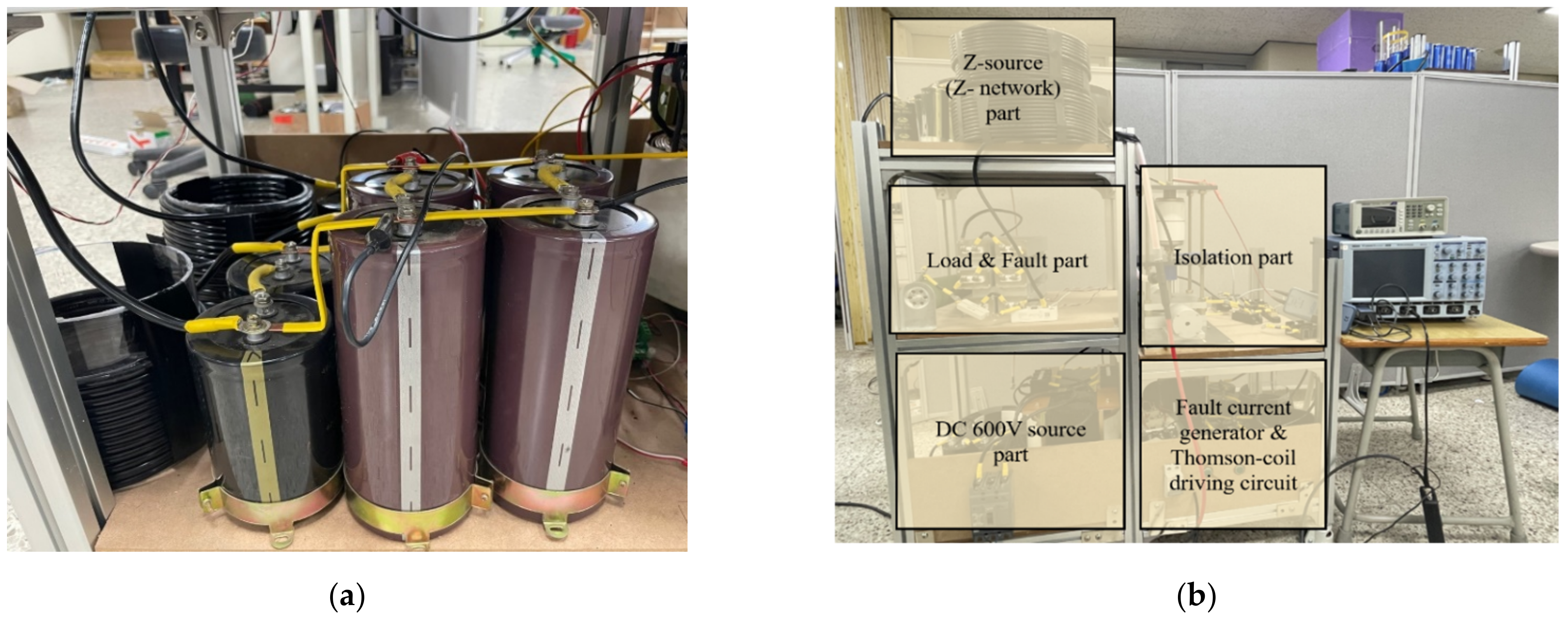
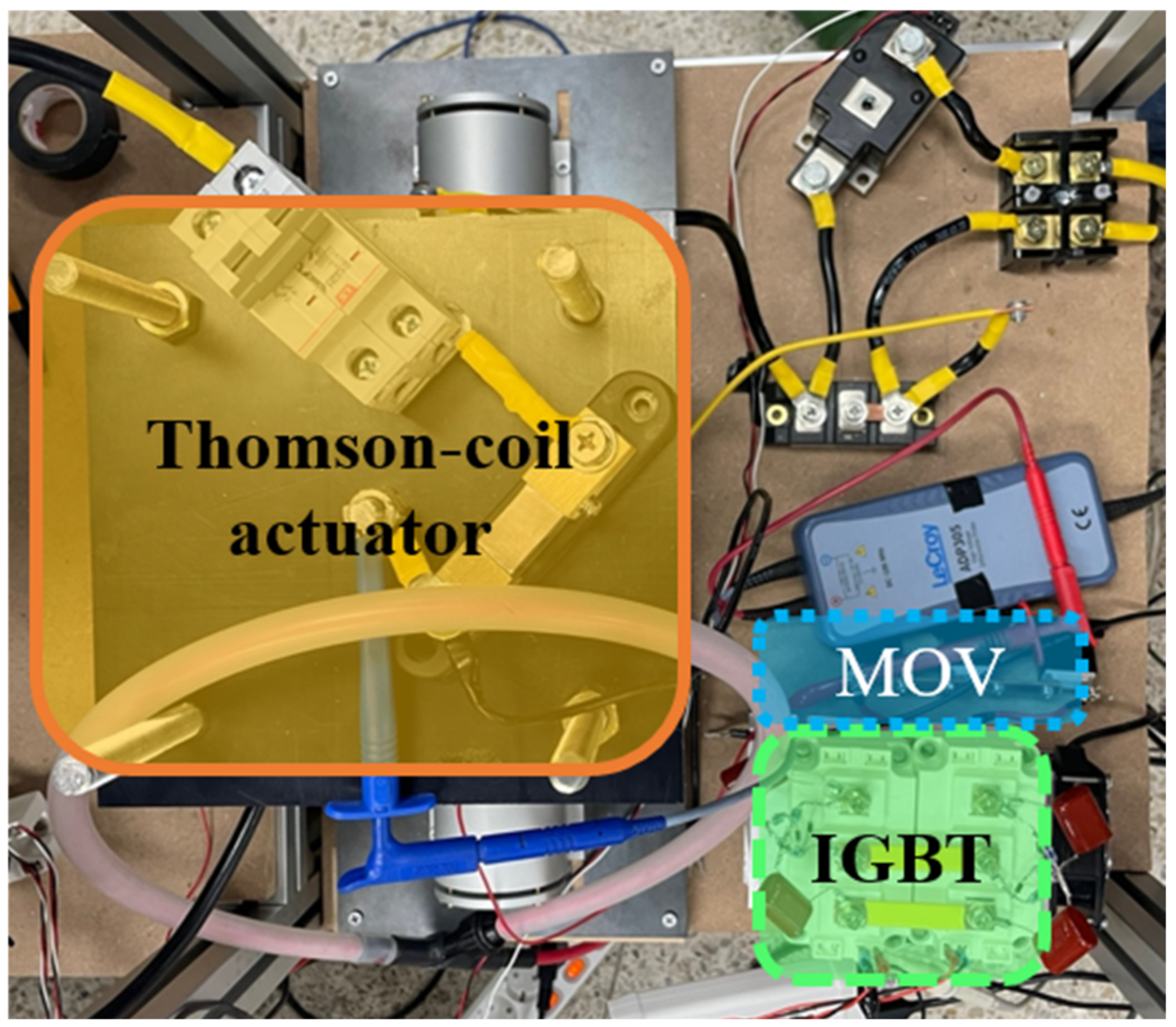
4.1. Experimental Setup

The proposed bidirectional HZCB was tested on a 600 V DC power supply due to limited conditions in the laboratory. However, in order for the Thomson coil actuator to operate as designed, a current of 7 kA must be passed, so the driving circuit was constructed using a capacitor in Figure 9a. In order to simulate that the circuit breaker operates immediately when a fault occurs, the current discharge and fault circuit in the driving circuit were set to occur simultaneously. This is described in Section 4.2. The load current was 2.5 A, and the fault circuit resistance was selected as 1 ohm. At this time, the parameters of the experimental components are shown in Table 2, and the overall configuration of the experimental device is shown in Figure 9b.
Figure 10 is the isolation part of HZCB. The isolation part consists of the Thomson coil actuator, which is a high-speed switch; IGBT; and MOV that limits overvoltage and absorbs energy. The IGBT used a SKM400GB12T4 of 1200 V 400 A, and the MOV was used by connecting MOVs with an operating voltage of 680 V and limit voltage of 1120 V in parallel. Since IGBTs are connected in series with different directions, the current flows through one diode and one transistor. Therefore, as shown in Figure 11, the experiment was conducted by connecting the diode and the IGBT in series.

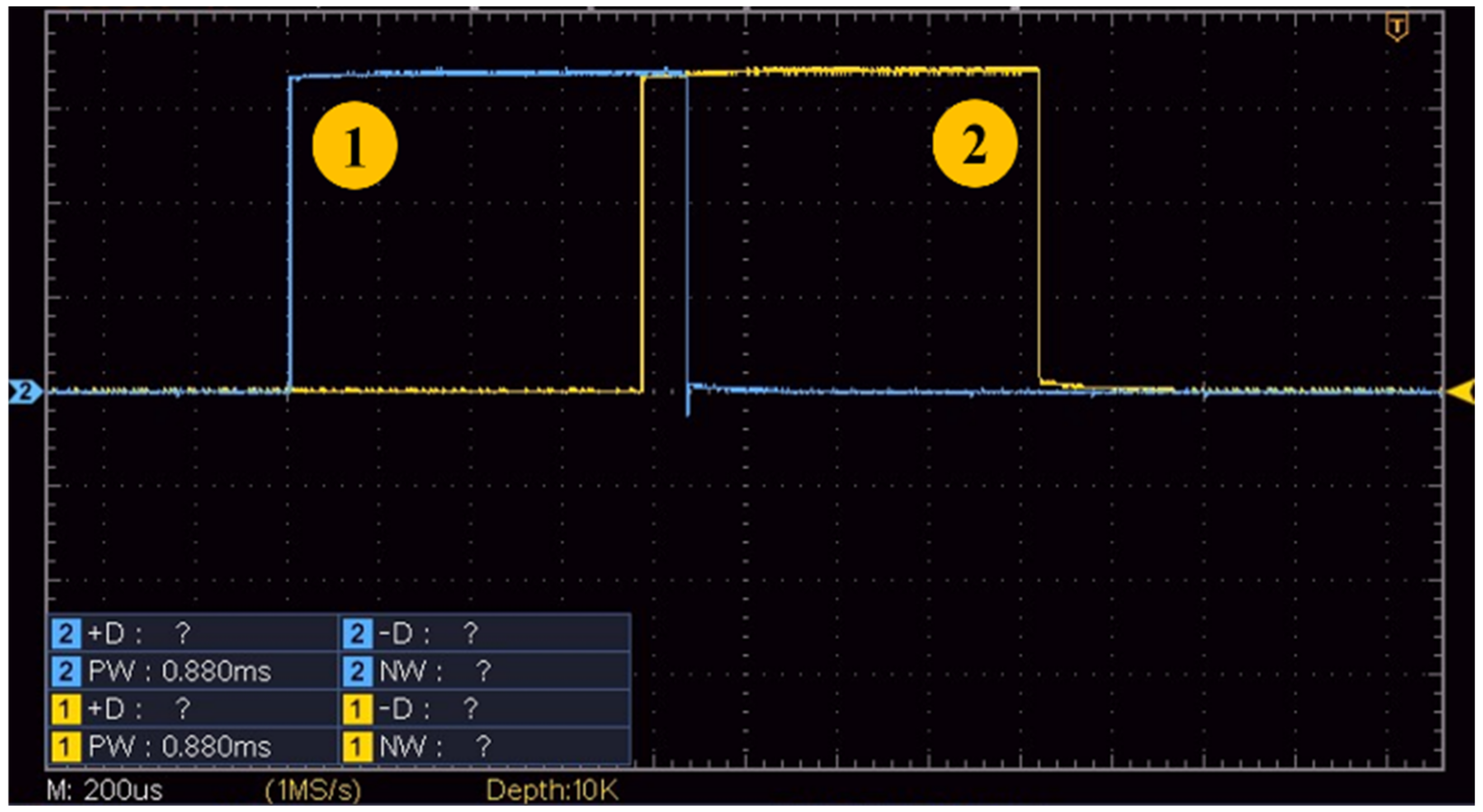
4.2. Experimental Control

Control of the experiment was controlled using a DSP. The DSP was set to output two different waveforms with one-shot pulses. As mentioned in Section 3, the Thomson coil is instantaneous with a 10 kV supply low impedance fault. In order to simulate that the circuit breaker operates immediately upon fault, a fault circuit signal and a Thomson coil operation signal were input at the same time. Waveform No. 1 was used as a signal for circuit failure and discharge of the Thomson coil drive circuit, and Waveform No. 2 was used as the operating waveform of the IGBT. The waveform is shown in Figure 11.

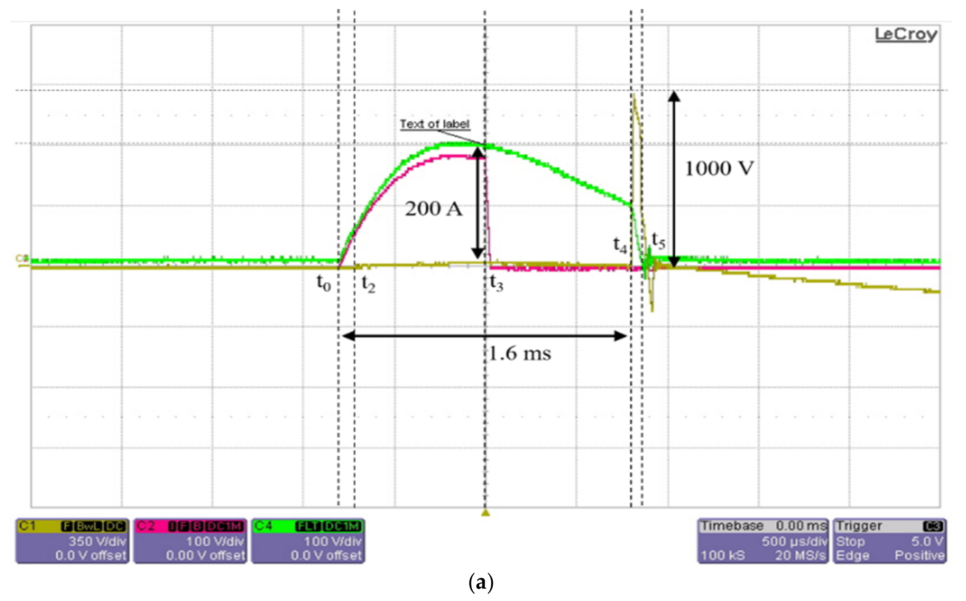
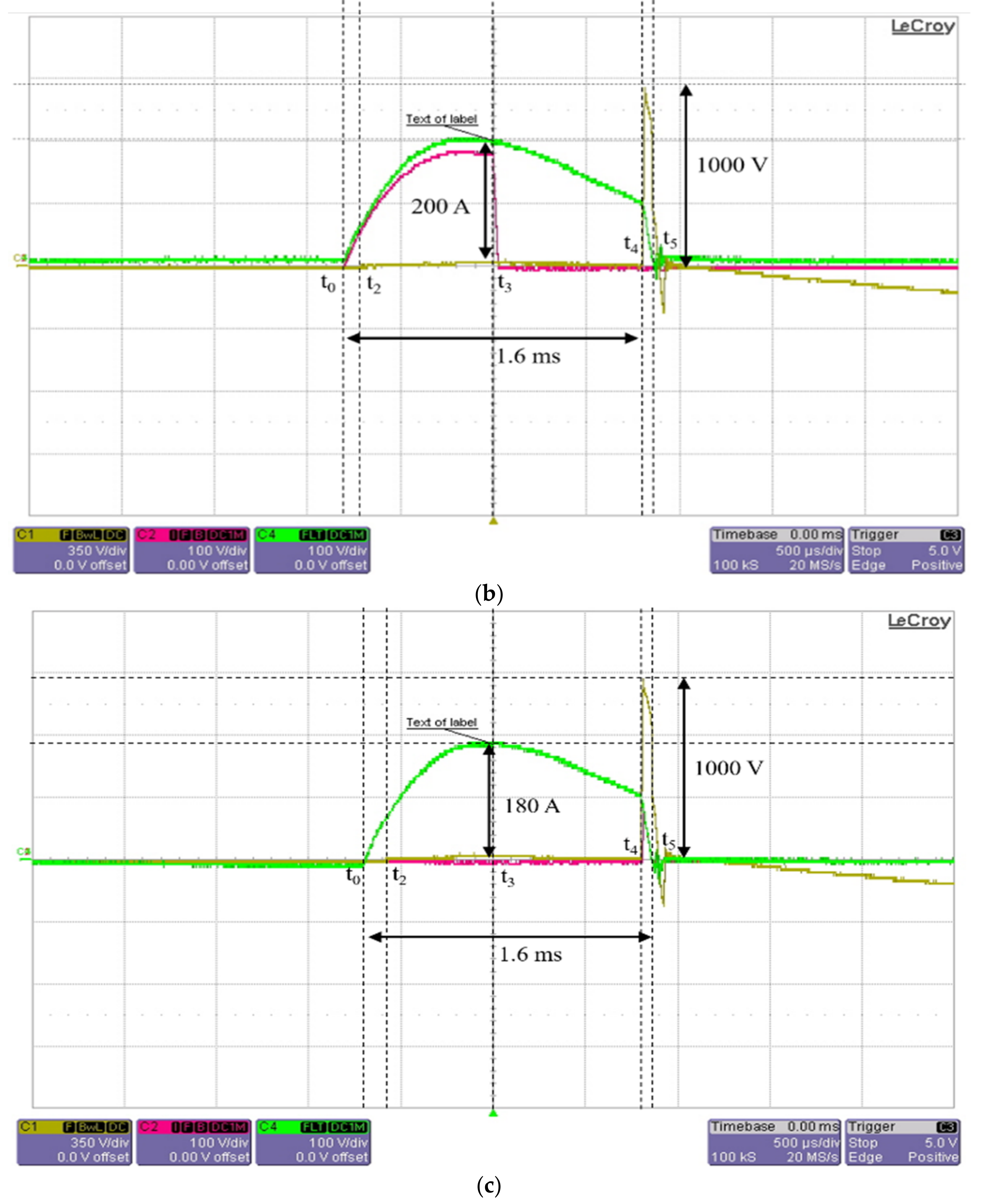
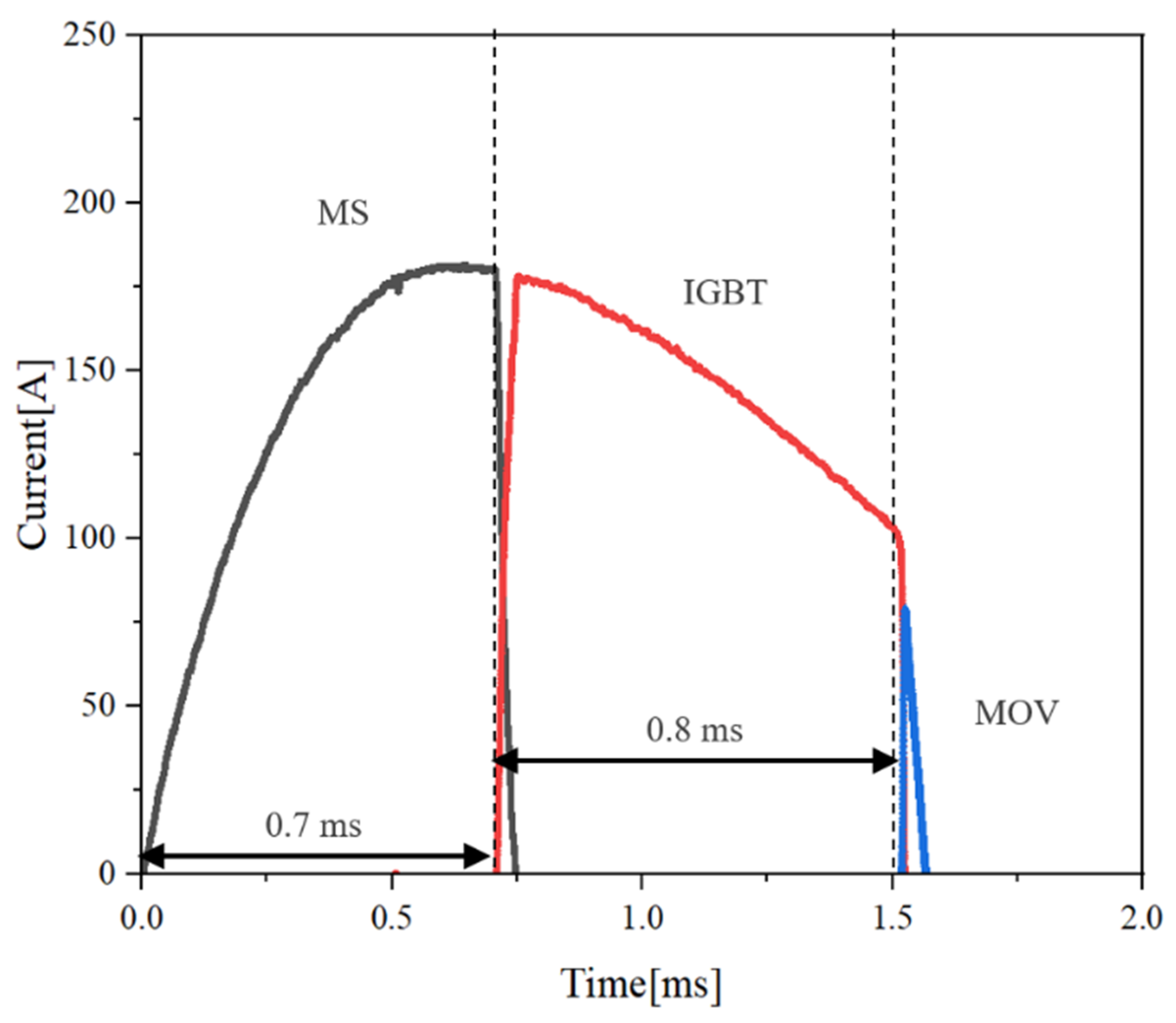
4.3. Experimental Results

The waveform measured as a result of the 600 V experiment is shown in Figure 12. The parameters of the test circuit are shown in Table 2. The green line is the total current measured by the Rogowski coil; the red line is the current flowing through MS, IGBT, and MOV measured by the Pearson coil; and the yellow line is the voltage across the switch.
Figure 12a is the current and total current flowing through the MS, Figure 12b is the current and total current flowing through the IGBT, and Figure 12c is the current and total current flowing through the MOV. The blue line in Figure 12b is the measured voltage of the IGBT’s control signal.
A fault is provided at t0, and the current flows directly into the capacitor path. At this time, the current flows through the Thomson coil and the contacts begin to separate, and the current is commuted to the IGBT. At t4, the IGBT is turned off, and after the MOV takes on the remaining current, the current becomes zero to isolate the fault. Looking at the measured waveforms, there is a difference between the measured values of the Rogowski coil and the Pearson coil. The reason is that the Rogowski coil can measure a maximum of 10 kA, so a relatively low current of about 200 A seems to be less accurate. On the other hand, the Pearson coil seems to have been measured more precisely because it used equipment up to 500 A.
After the IGBT turns off, the voltage across the breaker rises very significantly. A total of 1000 V, about 1.7 times the power supply voltage, was measured. Since the IGBT was turned off in the period where the current was lowered, it was seen that the voltage rose lower than the MOV’s clamping voltage of 1100 V. This means that the HZCB’s fault isolation method can reduce the MOV’s stress and reduce the MOV’s configuration capacity and size.
The proposed circuit breaker was tested a total of 20 times, and the fault isolation current waveform was measured six to seven times for each part. The total current flow as a result of measurement with the Pearson coil is shown in Figure 13 below.
The proposed circuit breaker successfully isolated the fault within 1.6 ms. After fault isolation, the short-term IGBT isolation recovery voltage was measured, and the voltage of the switch rose along with the supply voltage. Here, the fault isolation was set to be completed within 1.6 ms considering the safety factor of insulation recovery. However, it seems that this time can be further shortened because the voltage of the contact did not rise rapidly along the power supply voltage after fault isolation, but instead rose gently.
In the case of the two waveforms, the system inductance was limited to 1 mH, the power voltage was 600 V, and the short-circuit resistance was limited to 1 ohm. As shown in Figure 14, in the case of HZCB, a current zero point was created, so that the circuit breaker can block faster. In addition, it seems that the capacity and volume of the MOV could be reduced by reducing the burden current of the MOV.

5. Conclusions

The HZCB that can perform breaking operations in MVDC class systems is presented in this white paper. The presented scheme completed the breaking at the current zero point, minimizing the stress and reducing the volume of IGBTs and MOVs. In addition, in order to improve the breaking speed, the Thomson coil actuator was designed to operate immediately only in dangerous fault circuit currents such as low impedance fault. It is very important to consider that re-ignition or insulation breakdown did not occur when the hybrid circuit breaker operated. A detailed description of this design was presented. The proposed circuit breaker was verified experimentally. However, in reality, the volume and size of the inductor and capacitor in the Z-source method in a large-capacity system are limited by the length of the line. In addition, it is necessary to study the problem of transient voltage that occurs after the IGBT is turned off and the re-close method. Therefore, future research will proceed with large-capacity fault isolation research that can solve these problems.

Author Contributions

Conceptualization, H.-S.L.; methodology, H.-S.L.; formal analysis, H.-S.L.; investigation, H.-W.K.; software, H.-S.L. resources, H.-W.K., J.-H.R. and K.-A.L.; writing—original draft, H.-S.L.; writing—review and editing, K.-A.L. and J.-H.R.; supervision, K.-A.L.; funding acquisition, J.-H.R. All authors have read and agreed to the published version of the manuscript.

Funding

This work was supported by the National Research Foundation of Korea (NRF) grant funded by the Korean government (MSIT) (no. RS-2022-00166064).

Institutional Review Board Statement

Not applicable.

Informed Consent Statement

Not applicable.

Data Availability Statement

The data supporting the findings of this study are available from the first author or corresponding author upon reasonable request.

Conflicts of Interest

The authors declare no conflict of interest.

References

  1. Liao, J.; Zhou, N.; Qin, Z.; Purgat, P.; Wang, Q.; Bauer, P. Coordination control of power flow controller and hybrid DC circuit breaker in MVDC distribution networks. IEEE Mod. Power Syst. Clean Energy 2021, 9, 1257–1268. [Google Scholar] [CrossRef]
  2. He, Z.; Hu, J.B.; Lin, L. Pole-to-ground Fault Analysis for HVDC Grid Based on Common-and Differential-mode Transformation. J. Mod. Power Syst. Clean Energy 2020, 8, 521–530. [Google Scholar] [CrossRef]
  3. Xu, J.; Zhao, X.; Han, N. A thyristor-based DC fault current limiter with inductor inserting-bypassing capability. IEEE J. Emerg. Sel. Top. Power Electron. 2019, 7, 1748–1757. [Google Scholar] [CrossRef]
  4. Hategekimana, P.; Ferre, A.J.; Bernuz, J.M.R.; Ntagwirumugara, E. Fault Detecting and Isolating Schemes in a Low-Voltage DC Microgrid Network from a Remote Village. Energies 2022, 15, 4460. [Google Scholar] [CrossRef]
  5. Franck, C.M. HVDC Circuit Breakers: A Review Identifying Future Research Needs. IEEE Trans. Power Deliv. 2011, 26, 998–1007. [Google Scholar] [CrossRef]
  6. Pei, X.; Cwikowski, O.; Vilchis-Rodriguez, D.S.; Barnes, M.; Smith, A.C.; Shuttleworth, R. A review of technologies for MVDC circuit breakers. In Proceedings of the IECON 2016—42nd Annual Conference of the IEEE Industrial Electronics Society, Florence, Italy, 23–26 October 2016; pp. 3799–3805. [Google Scholar]
  7. Mokhberdoran, A.; Carvalho, A.; Leite, H.; Silva, N. A review on HVDC circuit breakers. In Proceedings of the 3rd Renewable Power Generation Conference (RPG 2014), Naples, Italy, 24–25 September 2014; pp. 1–6. [Google Scholar]
  8. Wu, Y.; Hu, Y.; Wu, Y.; Rong, M.; Yi, Q. Investigation of an active current injection DC circuit breaker based on a magnetic induction current commutation module. IEEE Trans. Power Deliv. 2018, 33, 1809–1817. [Google Scholar] [CrossRef]
  9. Shi, Z.; Zhang, Y.; Jia, S.; Song, X.; Wang, L.; Chen, M. Design and numerical investigation of a HVDC vacuum switch based on artificial current zero. IEEE Trans. Dielectr. Electr. Insul. 2015, 22, 135–141. [Google Scholar] [CrossRef]
  10. Beheshtaein, S.; Cuzner, R.; Savaghebi, M.; Guerrero, J.M. Review on microgrids protection. IET Gener. Transm. Distrib. 2019, 13, 743–759. [Google Scholar] [CrossRef]
  11. Mokhberdoran, A.; Carvalhoa, A.; Silva, N.; Leite, H.; Carrapatoso, A. Design and implementation of fast current releasing DC circuit breaker. Electr. Power Syst. Res. 2017, 151, 218–232. [Google Scholar] [CrossRef]
  12. Miao, Z.; Sabui, G.; Roshandeh, A.M.; Shen, Z.J. Design and Analysis of DC Solid-State Circuit Breakers Using SiC JFETs. IEEE J. Emerg. Sel. Top. Power Electron. 2016, 4, 863–873. [Google Scholar] [CrossRef]
  13. Mohammadi, F.; Nazri, G.-A.; Saif, M. A New Topology of a Fast Proactive Hybrid DC Circuit Breaker for MT-HVDC Grids. Sustainability 2019, 11, 4493. [Google Scholar] [CrossRef]
  14. Shukla, A.; Demetriades, G.D. A Survey on Hybrid Circuit-Breaker Topologies. IEEE Trans. Power Deliv. 2014, 30, 627–641. [Google Scholar] [CrossRef]
  15. Mokhberdoran, A.; Van Hertem, D.; Silva, N.; Leite, H.; Carvalho, A. Multiport hybrid HVDC circuit breaker. IEEE Trans. Ind. Electron. 2018, 65, 309–320. [Google Scholar] [CrossRef]
  16. Nguyen, V.-V.; Son, H.-I.; Nguyen, T.-T.; Kim, H.-M.; Kim, C.-K. A novel topology of hybrid HVDC circuit breaker for VSC-HVDC application. Energies 2017, 10, 1675. [Google Scholar] [CrossRef]
  17. Khalid, S.; Raza, A.; Alqasemi, U.; Sobahi, N.; Yousaf, M.Z.; Abbas, G.; Jamil, M. Technical Assessment of Hybrid HVDC Circuit Breaker Components under M-HVDC Faults. Energies 2021, 14, 8148. [Google Scholar] [CrossRef]
  18. Corzine, K.A.; Ashton, R.W. Structure and analysis of the Z-source MVDC breaker. In Proceedings of the 2011 IEEE Electric Ship Technologies Symposium, Alexandria, VA, USA, 10–13 April 2011; pp. 334–338. [Google Scholar]
  19. Corzine, K.A.; Ashton, R.W. A new Z-source DC circuit breaker. IEEE Trans. Power Electron. 2012, 27, 2796–2804. [Google Scholar] [CrossRef]
  20. Maqsood, A.; Overstreet, A.; Corzine, K.A. Modified Z-Source DC Circuit Breaker Topologies. IEEE Trans. Power Electron. 2016, 31, 7394–7403. [Google Scholar] [CrossRef]
  21. Chang, A.H.; Sennett, B.R.; Avestruz, A.T.; Leeb, S.B.; Kirtley, J.L. Analysis and design of DC system protection using Z-source circuit breaker. IEEE Trans. Power Electron. 2015, 31, 1036–1049. [Google Scholar] [CrossRef]
  22. Savaliya, S.G.; Fernandes, B.G. Analysis and Experimental Validation of Bidirectional Z-Source DC Circuit Breakers. IEEE Trans. Ind. Electron. 2019, 67, 4613–4622. [Google Scholar] [CrossRef]
  23. Ryan, D.J.; Torresan, H.D.; Bahrani, B. A bidirectional series Z-source circuit breaker. IEEE Trans. Power Electron. 2017, 33, 7609–7621. [Google Scholar] [CrossRef]
  24. Shu, J.; Wang, S.; Ma, J.; Liu, T.; He, Z. An Active Z-Source DC Circuit Breaker Combined with SCR and IGBT. IEEE Trans. Power Electron. 2020, 35, 10003–10007. [Google Scholar] [CrossRef]
  25. Mackey, L.; Rachi, M.R.K.; Peng, C.; Husain, I. Optimization and control of a z-source, ultrafast mechanically switched, high-efficiency dc circuit breaker. IEEE Trans. Ind. Appl. 2020, 56, 2871–2879. [Google Scholar] [CrossRef]
  26. Hyunseung, L.; Young, C.; Kuna, L.; Jaeho, R. Fast Fault Detection and Active Isolation of Bidirectional Z-Source Circuit Breaker with Mechanical Switch. Energies 2022, 15, 8899. [Google Scholar]
  27. Peng, C.; Song, X.; Huang, A.Q.; Husain, I. A Medium-Voltage Hybrid DC Circuit Breaker—Part II: Ultrafast Mechanical Switch. IEEE J. Emerg. Sel. Top. Power Electron. 2017, 5, 289–296. [Google Scholar] [CrossRef]
  28. Slade, P.G. The Vacuum Interrupter, 1st ed.; CRC Press: Boca Raton, FL, USA, 2018. [Google Scholar]
  29. Vilchis-Rodriguez, D.S.; Shuttleworth, R.; Barnes, M. Finite element analysis and efficiency improvement of the Thomson coil actuator. In Proceedings of the 8th IET International Conference on Power Electronics, Machines and Drives (PEMD 2016), Glasgow, UK, 19–21 April 2016. [Google Scholar]
  30. Zhu, Z.; Yuan, Z.; Chen, L.; He, J.; Zhu, Z. Vibration Characteristics of Thomson Coil Actuator Based on Simulation and Experiments. IEEE Trans. Energy Convers. 2020, 35, 1228–1237. [Google Scholar] [CrossRef]
  31. Wu, Y.; Wu, Y.; Rong, M.; Yang, F.; Zhong, J.; Li, M.; Hu, Y. A new Thomson coil actuator: Principle and analysis. IEEE Trans. Compon. Packag. Manuf. Technol. 2015, 5, 1644–1655. [Google Scholar]
  32. Vilchis-Rodriguez, D.S.; Shuttleworth, R.; Smith, A.C.; Barnes, M. Design, Construction, and Test of a Lightweight Thomson Coil Actuator for Medium-Voltage Vacuum Switch Operation. IEEE Trans. Energy Convers. 2019, 34, 1542–1552. [Google Scholar] [CrossRef]
  33. Lequesne, B.; Holp, T.; Schmalz, S.; Slepian, M.; Wang, H. Frequency-Domain Analysis and Design of Thomson-Coil Actuators. In Proceedings of the 2021 IEEE Energy Conversion Congress and Exposition (ECCE), Vancouver, BC, Canada, 10–14 October 2021; pp. 4081–4088. [Google Scholar]
Figure 1. Schematic of the proposed hybrid Z-source circuit breaker. (a) Schematic; (b) normal conduction; (c) fault conduction in MS; (d) fault conduction in IGBT; (e) fault conduction in MOV, energy dissipation; and (f) fault isolation complete.
Energies 17 00069 g001
Figure 2. Current and voltage of a hybrid Z-source DC circuit breaker during the interruption.
Energies 17 00069 g002
Figure 3. Equivalent circuit of the Z-source circuit breaker during the interruption.
Energies 17 00069 g003
Figure 4. Vacuum breakdown voltage.
Energies 17 00069 g004
Figure 5. Thomson coil actuator.
Energies 17 00069 g005
Figure 6. Z-source circuit breaker fault current.
Energies 17 00069 g006
Figure 7. Simulation result of Thomson coil force and inject current.
Energies 17 00069 g007
Figure 8. FEM simulation result, plate displacement and speed at 7 kA.
Energies 17 00069 g008
Figure 9. Experimental setup. (a) Thomson coil drive circuit. (b) Full device configuration.
Energies 17 00069 g009
Figure 10. HZCB experimental setup, isolation part.
Energies 17 00069 g010
Figure 11. DSP output wave form control signal.
Energies 17 00069 g011
Figure 12. HZCB experimental waveform. Red line is (a) MS current, (b) IGBT current, and (c) MOV current; green line is all currents; blue line is the IGBT control signal; and yellow line is voltage.
Energies 17 00069 g012aEnergies 17 00069 g012b
Figure 13. HZCB fault current measurement waveform.
Energies 17 00069 g013
Figure 14. Comparison of fault current isolation between HZCB and HCB. (a) Fault current flow of HZCB. (b) Fault current flow of HCB.
Energies 17 00069 g014
Table 1. Parameters of the simulation circuit.
SymbolQuantityValue
VSSource voltage10 kV
C0, C1, C2Impedance network capacitance1 mF
RLLoad resistance1 kΩ
RfFault resistance1 mΩ
L1, L2Impedance network inductance4 mH
LSYS1, LSYS2System inductance1 mH
Table 2. Parameters of the test circuit.
SymbolQuantityValue
VSSource voltage600 V
C0, C1, C2Impedance network capacitance1 mF
RLLoad resistance250 Ω
RfFault resistance1 Ω
L1, L2Impedance network inductance4 mH
LSYS1, LSYS2System inductance1 mH
Disclaimer/Publisher’s Note: The statements, opinions and data contained in all publications are solely those of the individual author(s) and contributor(s) and not of MDPI and/or the editor(s). MDPI and/or the editor(s) disclaim responsibility for any injury to people or property resulting from any ideas, methods, instructions or products referred to in the content.

