Abstract
The International Maritime Organization are introducing more and more stringent requirements concerning increasing ships’ energy efficiency. They are becoming a huge challenge for design engineers. This article proposes a method to increase the energy efficiency of mechatronic drive systems in ship systems via the use of highly efficient electric permanent magnet synchronous motors (PMSMs). An innovative control strategy is suggested. It is based on the modification of the classic PMSM control and ensuring energy optimization through a reduction in reactive power in the Active Converter–PMSM system. Analytical and simulation studies using the Matlab–Simulink program are presented. They confirm the possibility of reducing reactive power in a PMSM drive system. A verification of the results of analytical and simulation examinations was conducted at a laboratory station with the use of the Speedgoat module operating in the Rapid Control Prototyping mode. Both the simulation and experimental research results indicate the effectiveness of the proposed PMSM control method. This method has good prospects for application in energy-saving marine drive systems.
1. Introduction
80% of world trade is carried by sea. Maritime transport produces approximately 29% of global CO2 emissions [1]. According to the Marine Environmental Protection Committee (MEPC), the target is to reduce CO2 emissions generated by ships by 50% by 2050 [2]. Energy efficiency is becoming increasingly important in the current global economic and environmental scenario. In this context, the International Maritime Organization (IMO) has presented rigorous regulations regarding the design of ship systems by introducing the Energy Efficiency Design Index (EEDI). This index is a measure of energy efficiency for newly built ships [3,4,5,6]. EEDI is calculated on the basis of the ship’s design values and used to determine its energy efficiency during design. The EEDI is defined in the following way [7,8,9,10]:
CO2 emission is calculated on the basis of fuel consumption, which results from the power used for the main drive and auxiliary equipment of the ship, measured under specific design assumptions. The work performed to transport cargo is estimated by multiplying the design tonnage and the ship’s speed measured for the corresponding draft. The IMO determined a time sequence for tightening global regulations in terms of EEDI [9] (Figure 1), posing huge challenges to designers and engineers due to technological limitations (e.g., the possibility of increasing the efficiency of the ship’s main propulsion engines).
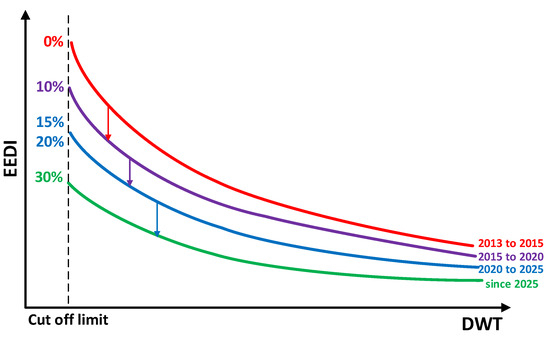
Figure 1.
Regulations regarding EEDI level requirements in subsequent years.
As presented in many works [11,12,13,14,15], the effectiveness of the determined EEDI is not fully adequate for an improvement in the ship’s carbon footprint. However, it is certain that a real increase in the energy efficiency of ship systems (by reducing losses) will reduce the emission of air pollution by ships while improving the economic effect.
In this article, the authors propose increasing ships’ energy efficiency by:
- Replacing the commonly used synchronous motor with electromagnetic excitation with a PMSM on ships with an electric main drive (diesel–electric [16]). In this case, a PMSM’s efficiency is higher by 3–6%, especially at low speeds [17]. The use of a PMSM for the ship’s main drive is possible thanks to the development of the technology of synchronous machines with permanent magnets. Currently, obtaining a PMSM power of several MW is not a problem [18].
- Replacing the commonly used squirrel cage motor on ships in the auxiliary systems of the ship’s power plant and onboard systems with a PMSM. In this case, the efficiency of a PMSM is higher by 5–18%, especially at low speeds [19,20]. An example is a mooring winch system (on large ships, there may be 7–9 winches working simultaneously with a power of several dozen kW each), where, among other things, it is necessary to control the electric drive with high torque at low speeds.
- Modifying the classic PMSM control in order to reduce reactive power Q in the Active Converter (AC)–PMSM system (Q = 0). The increase in efficiency in this case results from a reduction in losses in the AC-PMSM system. For example, in the “Shore To Ship” system [21], losses in transmission lines (between the AC and the machine) and losses in the AC (switching losses in the AC and losses in the AC related to the fundamental harmonic), when reducing reactive power to zero (Q = 0), were reduced by several percent [22].
At this point, it should be explained that in recent years, there have been considerations and testing of the use of PMSMs as the main propulsion for ships due to the technological development of these machines in terms of nominal power (for example, PMSMs with a power of 36 MW have been tested on military ships [23]). PMSMs are attractive due to their energy efficiency, performance, as well as smaller dimensions and mass compared to traditional diesel engines, and they can be particularly beneficial in applications where energy savings and emission reduction are crucial [24,25]. The scientific literature on the possibilities of using PMSMs in propulsion systems is broad, especially in the context of PMSM control [26]. Currently, permanent magnet machines on ships are used primarily in mechatronic power plant systems (shaft generators) and to drive low-power ships (1–2 MW).
The authors did not find publications regarding the use of PMSMs in auxiliary devices on ships. In a ship’s engine room and onboard equipment, the number of commonly installed induction motors can reach several hundred, but not all systems can be replaced by PMSMs. This is primarily due to economic conditions (the price of PMSMs is several times higher than that of induction motors) and the complex control system of a PMSM. However, there are systems in which the use of PMSMs is justified due to their favorable mechanical properties (high starting torque and the ability to maintain high electromagnetic torque at low speeds). An example of such a system could be an air start compressor system or the previously mentioned windlass and anchor winch system.
A separate problem is improving the efficiency of a PMSM drive by reducing the reactive power during energy conversion (popularly called power factor correction—PFC). Reducing reactive power in the system allows for a decrease in losses associated with this power.
There are many methods for reducing reactive power in PMSM drive systems, but the scientific literature primarily focuses on the active rectifier circuit (power supply circuit) of the mechatronic system [27,28,29,30,31] (Figure 2).
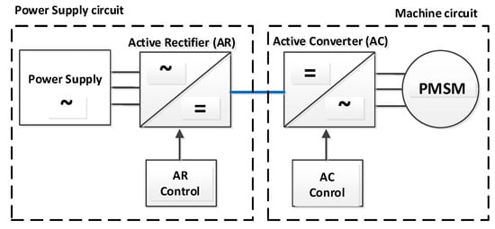
Figure 2.
Mechatronic drive system with PMSM.
In this article, the authors present a method for reducing reactive power in the AC-PMSM circuit (machine circuit). Reducing reactive power in the machine circuit helps to decrease losses in the AC, in the PMSM, and in the usually short transmission line. The literature on reducing reactive power in the machine circuit is limited, and the presented methods are characterized by complex control algorithms and are not fully optimal in terms of efficiency [32,33].
The purpose of the analysis and research presented by the authors in the article is to confirm the effectiveness of the proposed AC control method in reducing reactive power in the PMSM circuit while ensuring good mechanical properties in the machine.
It is worth mentioning that there are known methods of maintaining cos φ = 1, i.e., reactive power Q = 0 in drive systems, but in the context of synchronous machines with electromagnetic excitation (with adjustable excitation current) [34].
2. Methods
A substitute diagram of the AC–PMSM circuit (machine circuit) is presented in Figure 3.
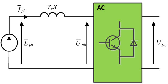
Figure 3.
Substitute diagram of the AC–PMSM circuit (machine circuit).
The mathematical description of a PMSM was performed in a synchronously rotating coordinate system (d, q), using the generalized vector method [35,36,37] and the “fundamental harmonic” method [38]. In the coordinate system, the d axis coincides with the axis of the rotor’s magnetic flux, and the perpendicular q axis coincides with the axis of the electromotive force. The mathematical description is as follows:
where:
—fundamental harmonic of phase voltage and current vectors (the AC output voltage and current contain many harmonics (especially voltage); analysis is only concerned with the fundamental harmonic);
—the flux vector of PMSM excitation;
p—the number of pairs of magnetic poles;
ωm—the angular speed of PMSM rotor rotation (this is so-called mechanical speed);
ω—the angular speed of sinusoidal state variables in the machine (this is so-called electric speed),
Te—PMSM electromagnetic torque;
TL—load torque;
—moment of inertia;
r, L—resistance and inductance of phase stator windings.
The control method proposed in this article—field-oriented control (FOC)—is commonly used for machines with permanent magnets, using it mainly as a torque regulator.
The mathematical analysis of the FOC control of the PMSM was carried out in a steady state. Then, Equation (2) can be presented as follows:
where:
—PMSM electromotive force (called back EMF induced in the stator windings originating from rotating permanent magnets).
For speeds below the nominal speed ω < ωN, the current set in the d axis is equal to 0 (Id = 0) in order to maximize the torque [34,37,39]. For speed ω > ωN, it is possible to weaken the field by reducing the stator flux in the d axis in different ways (e.g., [40]) in order to operate above the nominal speed, but this case is not considered in this article.
Assuming that Id = 0 current and Iph(1) = Iq, Equation (3) will take the following form:
Figure 4a presents a vector diagram for the AC-PMSM system with the classic FOC control. The reactive power in such a system is determined by the phase shift between the current Iph and voltage Uph ().
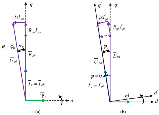
Figure 4.
Vector diagram of the AC-PMSM system (a) with the classic FOC control—phase angle between Uph and Iph ; (b) with energy optimized control (Q = 0)—phase angle between Uph and Iph .
The article proposes a change in control by shifting the d, q coordinate system by the angle . In the new coordinate system (d′, q′), the phase shift between the current I′ph and voltage Uph was equal to zero ( = 0), i.e., the reactive power Q in the AC-PMSM circuit was equal to zero (Q = 0) [41].
Determination of the angle results from simple trigonometric relationships (Figure 4b):
What is very important and results from Formula (5) is that the value of reactive power Q in the AC-PMSM system depends on the stator current Iph and PMSM parameters (L, ).
In marine systems, in which asynchronous squirrel cage motors are commonly installed, the power factor is on average approx. cosϕ = 0.8 [42].
Table 1 shows the nominal parameters of machines with permanent magnets of different power ratings with the calculated or indicated power factor (cosϕN) [43,44,45,46,47]. The PMSM is marked in green, and it will be subjected to analytical, simulation, and experimental tests later in the article.

Table 1.
Parameters of selected PMSM machines. The motor used in analytical, simulation and experimental studies is marked in green [43,44,45,46,47].
3. Results
3.1. The Results of Analytical Studies
Active and reactive power in the AC—PMSM circuit can be presented in the following form [16]:
Assuming that the PMSM control will be implemented for a speed of , the current in the d axis will be equal to zero (Id = 0), and Equation (6) will be simplified to the following form:
The current in q and d axes can be determined from the equations:
On the basis of Equations (4), (5), (7) and (8), Figure 4, and the PMSM parameters (the values marked in green in Table 1), the dependencies between active power P and reactive power Q and the speed ωm and the electromagnetic moment Te (Figure 5) can be determined in an analytical way.
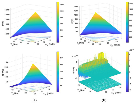
Figure 5.
Energy characteristics of active power P and reactive power Q, depending on the speed ωm and electromagnetic torque Te in the AC-PMSM system (obtained analytically in Matlab) with the classic FOC control (a) and with energy-optimized FOC control (b).
The analytical test results presented in Figure 5 prove the correctness of the assumptions and the analysis. With energy-optimized control, the reactive power Q in the AC-PMSM system is reduced to zero while maintaining the static properties connected with the active power P.
3.2. The Results of Simulation Studies
The presented control strategy was validated in simulation studies. The PMSM control model with the possibility of energy optimization in the AC-PMSM system was implemented in the Matlab–Simulink program (Figure 6).
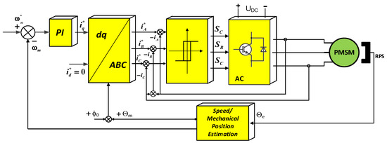
Figure 6.
PMSM control system according to the FOC method with the possibility of energy optimization in the AC-PMSM system (Q = 0) implemented in the Matlab–Simulink program.
FOC method control: both classical and modified according to the energy criterion use rotor position information, which ensures the synchronous operation of the AC and PMSM so that the motor cannot “fall out” of synchronism.
In the topology of the control system presented in Figure 6 using the FOC method with hysteresis current controllers, it is necessary to transform the current components in the d, q axes of the rotating coordinate system to the stationary ABC coordinate system. The relationship between the d, q system and ABC is defined using the Clarke–Park transformation [36,37]. It should be noted that the FOC method provides a decoupling of state variables: the flux and electromagnetic torque of the motor. The current Iq is the stator current component responsible for the torque Te and, consequently, for the speed (within the range ωm < ωmN Id = 0). The rotation angle Q of the d, q coordinate system is essential for determining the position of the coordinate system relative to the rotor flux. The reactive power Q in the AC-PMSM circuit under such control (using the classical FOC method) depends on the machine parameters and the stator current (Figure 4).
To reduce reactive power Q, it is proposed that the coordinate system be rotated by a small angle, ϕ0, determined from simple trigonometric relationships (Figure 4). This is equivalent to zeroing the reactive power (Q = 0) in the AC-PMSM circuit, as the angle between the voltage and phase current will be ϕ = 0 (Figure 4b).
Simulation tests were carried out at = 0 (without energy optimization) and at , determined automatically in accordance with the adopted idea (with energy optimization). A modification of the inverse Clarke–Park transform (dq/ABC) by adding the d, q coordination system of the optimization angle to the rotation angle enabled obtaining reactive power at zero level (Q = 0). Figure 5 and Figure 6 present the results of simulation tests comparing the system operation with the classic and modified FOC control at a given constant speed ω* and load change.
The results of PMSM performance with classical FOC control (Figure 7a) and with energy-optimized FOC control (Figure 7b) were compared for cases when the set speed ω* is kept constant and when, at t = 0.5 s, the load is activated stepwise.
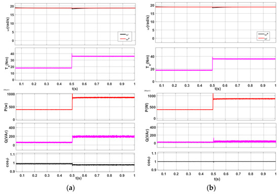
Figure 7.
PMSM simulation tests at constant set speed and variable load. Mechanical characteristics of rotational speed (ω—actual speed; ω*—set speed) and electromagnetic torque Te as well as energetic characteristics of power P, reactive power Q, and cosϕ in the AC–PMSM system (a) obtained with the classic FOC control and (b) with energy-optimized FOC control.
It should be noted that the adopted step change in the load while maintaining a constant speed can be considered a negative impact on the system (an example of such a situation could be the submergence of a ship propeller from the water when a ship is sailing in severe weather conditions). With classical FOC control (Figure 7a), the closed-loop system is stable, and the state of the system simply tracks the changing equilibrium point (the speed is maintained at a constant preset level). Energy characteristics (P = f(t), Q(f(t)) and power factor (PF = cosϕ) show the value and ratio of active and reactive power in the machine circuit. The change in active and reactive power is due to the change in load (that is, the change in Te).
With energy-optimized control (modification of the FOC method) (Figure 5b), the mechanical characteristics (speed, w, and electromagnetic torque, Te) are similar to those with classical FOC control. The mechatronic system does not lose its static and dynamic characteristics. Energy characteristics (P = f(t), Q(f(t)) and power factor (PF = Cos ϕ) show that the value of active power P is the same as with classical FOC control, and reactive power is reset to Q = 0 (PF = 1).
The results of PMSM operation with classical FOC control (Figure 8a) and with energy-optimized FOC control (Figure 8b) were compared for the case when the set speed ω* and load are increased stepwise at t = 0.5 s. It should be noted that the assumed step change in load when the set speed is changed can be considered the hardest (worst) impact on the system. Such extreme conditions allow us to confirm that the system will work properly under all conditions.
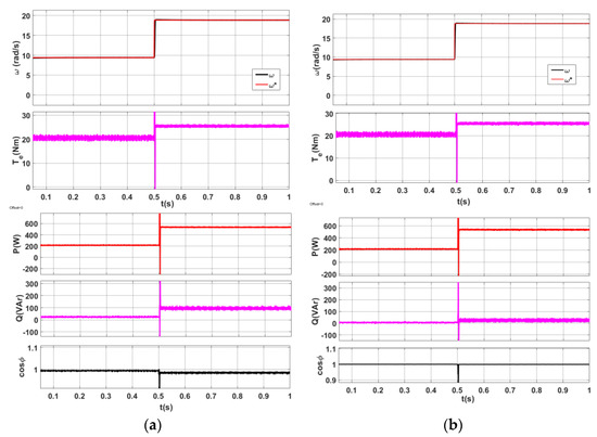
Figure 8.
PMSM simulation tests when changing the set speed and the load. Mechanical characteristics of rotational speed (ω—actual speed; ω*—set speed) and electromagnetic torque Te as well as energetic characteristics of active power P, reactive power Q, and cosϕ in the AC-PMSM system (a) obtained with the classic FOC control and (b) with energy-optimized FOC control.
As in Figure 7a, the PMSM mechatronic system with classical FOC control tracks the set speed and responds correctly to the increase in load (mechanical characteristics) (Figure 8a). Energy and power factor characteristics show the value and ratio of active and reactive power in the machine circuit, which changes with speed and torque. With energy-optimized control (a modification of the FOC method) (Figure 8b), the mechanical characteristics (speed, w, and electromagnetic torque, Te) are similar to those with classical FOC control. The mechatronic system does not lose its static and dynamic properties, and the energy characteristics of active and reactive power P, Q and power factor PF (PF = cosϕ) show that the reactive power is reset to Q = 0 (PF = 1), similarly to the first case.
3.3. The Results of Experimental Studies
In order to validate the results of analytical and simulation tests, a laboratory station for PMSM studies was built. An important element of the laboratory station is the Speedgoat module, which serves as a programmable AC controller, operating in real time with the use of the Matlab–Simulink package.
Here, it should be stressed that the model developed in the Matlab–Simulink environment used in the simulation studies could be easily utilized during experimental research, because the Speedgoat module is 100% compatible with Matlab–Simulink. The Rapid Control Prototyping (RCP) mode enables accelerating the process of developing control strategies and quickly performing experimental iterations in order to identify and solve potential problems. Mathworks and Speedgoat’s huge library facilitates design tasks. An examination of the control model in Matlab–Simulink paired in the Simulink Real-Time Target mode allows for a broad visualization of electrical, energy, and mechanical dependencies during the examination of the AC-PMSM system. Figure 9 presents the experimental test stand. On this stand, the PMSM drive was tested.
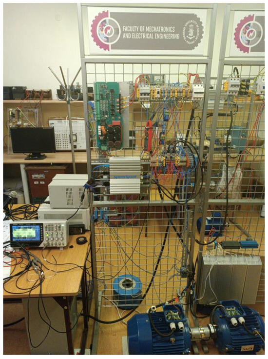
Figure 9.
Experimental test stand.
The main components of the experimental test stand were as follows:
- A Speedgoat Baseline Real-Time Target machine—2 GHz quad-core processor and I/O module with programmable FPGA and configurable digital TTL I/O functionality (PWM, encoders, SPI, I2C, SENT, etc.), plus eight single-ended/four differential analog inputs and four single-ended analog outputs;
- Three-phase inverter power unit based on an intelligent module with IGBT transistors (Mitsubishi PM50RLA120);
- A PMSM with a PMSG loaded with resistors (the machine parameters are in Table 1);
- A PC with the Matlab–Simulink program (ver.2021b);
- A Hall sensor (TLE4905L)—an amplifier and Schmitt trigger on one chip;
- An incremental encoder (Lika C82—Pulses Per Revolution (PPR): 1024).
A block diagram of the laboratory station is presented in Figure 10.
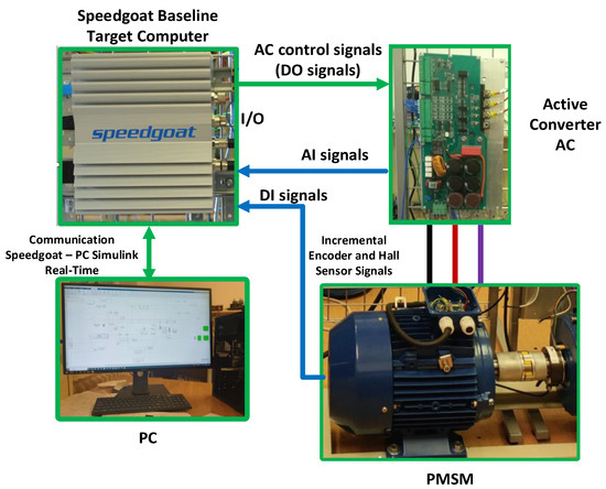
Figure 10.
Block diagram of the laboratory stand for PMSM testing.
3.3.1. Determination of the Rotor Position
A precise determination of the rotor position (determining the position of the d axis in the d, q coordinate system) is necessary for the PMSM drive system to operate in a stable and reliable manner.
Any error in determining the rotor position will result in an increase in the stator current Iph for obtaining a specific torque Te and in the creation of high reactive power in the AC-PMSM circuit.
In the first stage of experimental research, the authors installed a Hall effect sensor in the PMSM stator (Figure 11a), which enabled determining the position of the rotor in a simple and inexpensive way. This solution required a time correction due to the influence of the armature. Moreover, the resolution was insufficient for the tested PMSM (10 PPR); this resulted in a pulsation of rotational speed during measurement.
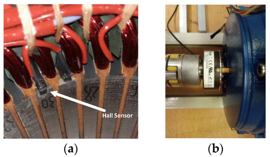
Figure 11.
Sensors allowing determination of the rotation angle of the d, q system, position of the d rotor axis and rotational speed ωm: (a) Hall effect sensor; (b) incremental encoder.
Therefore, in the second stage, an incremental encoder was installed (Figure 11b). Its resolution was 1024 PPR. In practice, the use of an incremental encoder is connected with a complex algorithm that estimates the approximate absolute position of the rotor when it is launched. After the initial analysis and starting the motor, the position is corrected to the precise setting [48].
The authors propose a different solution using a Hall effect sensor installed in the PMSM. The algorithm for determining the rotor position uses the Quadrature Decoder from the Speedgoat library. Its angle Θ for rotating the d, q coordinate system is zeroed with the use of a Hall effect sensor.
The motor is started without load at a specified speed according to the classic PWM control method. After zeroing the rotation angle Θ, the motor is switched to FOC for testing. It is possible to stop the motor and start it in a direct way—in accordance with the FOC method. Figure 12 presents a fragment of the PMSM control system model in the Matlab–Simulink program specifying the rotor’s position (in the d axis), rotation angle, and speed.

Figure 12.
The section of the control system model for PMSM in the Matlab–Simulink program determining the rotor position (in the d-axis), rotation angle, and speed.
3.3.2. The Results of Experimental Tests
Experimental studies of the PMSM were conducted following the procedure outlined in the simulation studies. The control system was developed based on Figure 6, utilizing the simulation-derived model implemented in the Matlab–Simulink program. Figure 13 shows a block diagram of the control system model implemented in Matlab–Simulink compiled into a Speedgoat processor unit running in real-time.
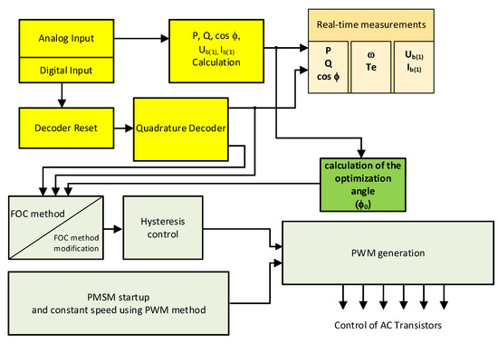
Figure 13.
The block diagram of the control system model implemented in Matlab–Simulink compiled into a Speedgoat processor unit running in real-time.
Figure 14 shows the results of the experimental tests with the classic FOC control and control with energy optimization at a given constant speed ω* and change in load.
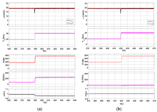
Figure 14.
Experimental tests of PMSM at constant set speed and variable load. Mechanical characteristics of rotational speed (ω—actual speed; ω*—set speed) and electromagnetic torque Te as well as energetic characteristics of active power P, reactive power Q, and cosϕ in the AC-PMSM system (a) obtained with the classic FOC control and (b) with energy-optimized FOC control.
Figure 15 presents the time courses of the fundamental harmonics of current and voltage of one phase with the classic FOC control and optimized control for the case indicated in Figure 12.
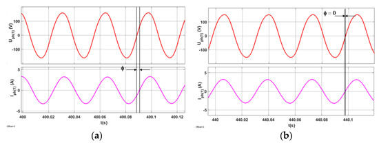
Figure 15.
Experimental tests of PMSM at constant set speed and variable load. Time characteristics of the fundamental harmonic of the phase voltage Uph(1) and the fundamental harmonic of the current Iph(1) in the AC-PMSM system (a) obtained with the classic FOC control and (b) with energy-optimized FOC control.
Comparing the results of experimental tests of PMSM operation with the classic FOC control (Figure 14a) and with energy-optimized FOC control (Figure 14b) for the case when the set speed ω* is maintained at a constant level and the load is activated in steps, the system with optimized control did not lose its static and dynamic properties. Simultaneously, reactive power was Q = 0 (cosϕ = 1). Comparing the time courses of the fundamental harmonics of current and voltage in the FOC control and optimized control (Figure 15), the effectiveness of optimization can be observed (angle ϕ = 0).
Figure 16 shows the results of experimental tests with the classic FOC control and optimized control obtained when changing the speed ω* and changing the load.
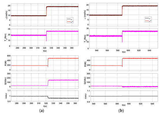
Figure 16.
Experimental tests of PMSM with changing set speed and variable load. Mechanical characteristics of rotational speed (ω—actual speed; ω*—set speed) and electromagnetic torque Te, as well as energetic characteristics of active power P, reactive power Q, and cosϕ in the AC-PMSM system (a) obtained with the classic FOC control and (b) with energy-optimized FOC control.
Figure 17 presents the time courses of the first harmonic of current and voltage with the classic FOC control and optimized control for the case indicated in Figure 14.
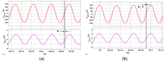
Figure 17.
Experimental tests of PMSM with changing set speed and variable load. Time characteristics of the fundamental harmonic of the phase voltage Uph(1) and the fundamental harmonic of the current Iph(1) in the AC-PMSM system (a) obtained with the classic FOC control and (b) with energy-optimized FOC control.
Comparing the results of the experimental tests of PMSM operation with the classic FOC control (Figure 16a) and with energy-optimized FOC control (Figure 16b) for the case when the set speed ω* and the load are increased in steps, the system with optimized control did not lose its static and dynamic properties. Simultaneously, reactive power was Q = 0 (cosϕ = 1). Comparing the time courses of the fundamental harmonic of current and voltage with the FOC control and optimized control (Figure 17), the effectiveness of the optimization can be observed (angle ϕ = 0).
4. Discussion and Conclusions
Continuous searches in ship systems to reduce losses and (consequently) to increase the ship’s energy efficiency pose great challenges for engineers.
The replacement of commonly used squirrel cage asynchronous motors (in ship auxiliary systems) and synchronous motors with electromagnetic excitation (in diesel–electric ships)—recommended by the authors—directly increases energy efficiency.
The article proposes an innovative method that enables a reduction in reactive power and, consequently, reduces losses in the AC-PMSM system. There are solutions that reduce the reactive power when powering the PMSM from power electronic converters, but these involve complicated control methods or modifications to the motor’s design [40,49,50,51]. The control system presented by the authors of this work is simple and easy to achieve.
The PMSM studies were conducted under the most unfavorable conditions, i.e.:
- A sudden change in load while maintaining a constant motor speed (Figure 7 in the simulation studies and Figure 14 in the experimental studies). The system response was fast. The transient state was associated with the FOC method that was applied (the method is based on a steady state). Such conditions apply, for example, to the main propulsion drive and are typical for a ship navigating in challenging weather conditions.
- A sudden change in the set speed with a simultaneous abrupt change in load was also examined (Figure 8 in the simulation studies and Figure 16 in the experimental studies). The system response was also fast. These conditions, for instance, apply to the operation of an electrically driven mooring winch.
The results of simulation tests presented in the article confirmed the results of the assumptions and analytical tests.
The validations were conducted in the experimental studies.
The contribution of the solution proposed in this article is therefore as follows:
- In marine electric drives, the replacement of commonly used electric machines with PMSMs is proposed. As the main electric propulsion of synchronous motors is electromagnetic excitation, and considering the electric propulsion of auxiliary equipment such as squirrel cage motors, this would significantly increase the efficiency of ship propulsion systems.
- The development of a PMSM control algorithm, which allows energy optimization according to the criterion of reactive power zeroing in an AC–PMSM system (Q = 0). The PMSM control algorithm developed and presented in the article makes it possible to achieve very good static and dynamic characteristics in the motor’s operation.
It should also be emphasized that the proposed solution to increase the energy efficiency of electric ship drives can also be used in electric propulsion systems on land, especially high-power ones, where energy optimization is important.
As mentioned earlier, during transient states, oscillations in torque and power at the moment of speed change were most noticeable in both simulation studies (Figure 5) and experimental investigations (Figure 14). This resulted from the principles of the FOC method, which is based on steady-state analysis. The authors are currently finalizing their work using a PMSM control method based on the “I/O linearization” technique with a nonlinear machine model and energy optimization (Q = 0). They are testing this method on the described laboratory setup. This approach will enable the control of PMSMs in transient states, which was not achievable with the FOC control.
One limitation discussed in the article was the use of an incremental encoder in experimental studies in conjunction with a Hall sensor. Despite accurately determining the rotor position (essential in the FOC method), motor startup required the use of PWM. In subsequent experimental studies, the authors plan to explore the possibility of using an absolute encoder, allowing the system to have information about the rotor position even when the motor is stationary.
5. Patents
German-Galkin, S.; Tarnapowicz, D.; and Staude, M. Method and speed control system for a permanent magnet synchronous motor (PMSM). Polish Patent Office. Patent application: 439070, 00-950 Warsaw, Niepodleglosci 188/192, Warsaw, 29 September 2021.
Author Contributions
Conceptualization, D.T., T.Z., Z.M. and M.J.; methodology, D.T. and T.Z.; software, D.T.; validation, D.T., T.Z., Z.M. and M.J.; formal analysis, D.T. and T.Z.; writing—original draft preparation, D.T.; writing—review and editing, visualization, D.T. All authors have read and agreed to the published version of the manuscript.
Funding
This research received no external funding.
Data Availability Statement
The data presented in this study are available from the corresponding authors upon reasonable request.
Conflicts of Interest
The authors declare no conflict of interest.
References
- EPA. Sources of Greenhouse Gas Emissions; EPA: Washington, DC, USA, 2016. Available online: https://www.epa.gov/sites/default/files/2016-08/documents/print_us-ghg-emissions-2016.pdf (accessed on 1 May 2023).
- Ancona, M.A.; Baldi, F.; Bianchi, M.; Branchini, L.; Melino, F.; Peretto, A.; Rosati, J. Efficiency improvement on a cruise ship: Load allocation optimization. Energy Convers. Manag. 2018, 164, 42–58. [Google Scholar] [CrossRef]
- IMO. RESOLUTION MEPC.203(62) Adopted on 15 July 2011. Available online: https://wwwcdn.imo.org/localresources/en/KnowledgeCentre/IndexofIMOResolutions/MEPCDocuments/MEPC.203(62).pdf (accessed on 5 May 2022).
- Polakis, M.; Zachariadis, P.; Kat, J.O. The Energy Efficiency Design Index (EEDI). In Sustainable Shipping; Springer: New York, NY, USA, 2019; pp. 93–135. [Google Scholar] [CrossRef]
- International Maritime Organization. IMO Train the Trainer (TTT) Course on Energy Efficiency Ship Operation. In Module 2—Ship Energy Efficiency Regulations and Related Guidelines; International Maritime Organization: London, UK, 2016; Available online: https://wwwcdn.imo.org/localresources/en/OurWork/Environment/Documents/Air%20pollution/TTT%20trainers%20manual%20final2.pdf (accessed on 5 May 2022).
- Grljušić, M.; Medica, V.; Radica, G. Calculation of Efficiencies of a Ship Power Plant Operating with Waste Heat Recovery through Combined Heat and Power Production. Energies 2015, 8, 4273–4299. [Google Scholar] [CrossRef]
- IMO. Annex 5, Resolution MEPC.245(66), Guidelines on the Method of Calculation of the Attained Energy Efficiency Design Index (EEDI) for New Ships; IMO: London, UK; EU: London, UK, 2014. [Google Scholar]
- IMO. MEPC 76, International Maritime Organization (IMO) Adopts Key Mandatory Measures to Reduce Ships’ Carbon Intensity; Establishes Ship Rating System. 2021. Available online: https://www.imo.org/en/MediaCentre/PressBriefings/pages/MEPC76.aspx (accessed on 11 March 2023).
- IMO. Ship Energy Efficiency Regulations and Related Guidelines. 2015. Available online: https://wwwcdn.imo.org/localresources/en/OurWork/Environment/Documents/Air%20pollution/M2%20TTT%20course%20Posters%20final1.pdf (accessed on 11 March 2023).
- Kang, J.-G.; Kim, M.-C.; Shin, Y.-J. Study on Compact Pre-Swirl Duct for Slender Aft-Body Crude Oil Carrier. J. Mar. Sci. Eng. 2022, 10, 396. [Google Scholar] [CrossRef]
- Trivyza, N.L.; Rentizelas, A.; Theotokatos, G. A Comparative Analysis of EEDI Versus Lifetime CO2 Emissions. J. Mar. Sci. Eng. 2020, 8, 61. [Google Scholar] [CrossRef]
- Lin, Y.; Yu, Y.; Guan, G. Research on energy efficiency design index for sea-going LNG carriers. J. Mar. Sci. Appl. 2014, 13, 430–436. [Google Scholar] [CrossRef]
- Ekanem Attah, E.; Bucknall, R. An analysis of the energy efficiency of LNG ships powering options using the EEDI. Ocean Eng. 2015, 110, 62–74. [Google Scholar] [CrossRef]
- Vladimir, N.; Ančić, I.; Šestan, A. Effect of ship size on EEDI requirements for large container ships. J. Mar. Sci. Technol. 2018, 23, 42–51. [Google Scholar] [CrossRef]
- Ancic, I.; Sestan, A.; Vladimir, N.; Klisaric, V. Influence of new power sources on the Attained EEDI. In Proceedings of the International Conference on Influence on Ship Design, London, UK, 24–25 September 2014. [Google Scholar]
- Zwierzewicz, Z.; Tarnapowicz, D.; German-Galkin, S.; Jaskiewicz, M. Optimal Control of the Diesel–Electric Propulsion in a Ship with PMSM. Energies 2022, 15, 9390. [Google Scholar] [CrossRef]
- Jamieson, P. Innovation in Wind Turbine Design; John Wiley & Sons, Ltd.: Hoboken, NJ, USA, 2011; ISBN 9780470699812. [Google Scholar] [CrossRef]
- Puranen, J. Permanent Magnet Machine vs. Induction Machine for In-Line Shaft Generator System. Theswitch, Version 1, 9/2021. Available online: https://theswitch.com/wp-content/uploads/2022/02/Marine_Talking_point_EN_PMM_IM_SG_comparison_20210929.pdf (accessed on 12 March 2023).
- Dambrauskas, K.; Vanagas, J.; Zimnickas, T.; Kalvaitis, A.; Ažubalis, M. A Method for Efficiency Determination of Permanent Magnet Synchronous Motor. Energies 2020, 13, 1004. [Google Scholar] [CrossRef]
- Deusinger, B.; Lehr, M.; Binder, A. Determination of efficiency of permanent magnet synchronous machines from summation of losses. In Proceedings of the 2014 International Symposium on Power Electronics, Electrical Drives, Automation and Motion, Ischia, Italy, 18–20 June 2014; pp. 619–624. [Google Scholar] [CrossRef]
- Tarnapowicz, D. Synchronization of national grid network with the electricity ships network in the “Shore to Ship” system. Manag. Syst. Prod. Eng. 2013, 3, 9–13. [Google Scholar]
- German-Galkin, S.; Tarnapowicz, D. Energy Optimization of the ‘Shore to Ship’ System-A Universal Power System for Ships at Berth in a Port. Sensors 2020, 20, 3815. [Google Scholar] [CrossRef] [PubMed]
- Corey, C.; Castles, G.; Wilgress-Pipe, C.; Moon, H. Electric Propulsion for Modern Naval Vessels. In Proceedings of the Conference: MADEX 2021, International Maritime Defense Industry Exhibition, Busan, Republic of Korea, 9–12 June 2021. [Google Scholar]
- The Switch. The Sound of Silence: Permanent Magnet Machines for Silent Vessels. Available online: https://theswitch.com/articles-2018/permanent-magnet-machines-for-silent-vessels/ (accessed on 10 December 2023).
- Bogomolov, M.D. Concept Study of 20 MW High-Speed Permanent Magnet Synchronous Motor for Marine Propulsion; The Department of Electrical Engineering of the Eindhoven University of Technology: Eindhoven, The Netherlands, 2023; ISBN 978-90-444-1191-1. Available online: https://pure.tue.nl/ws/portalfiles/portal/4285340/750674.pdf (accessed on 10 December 2023).
- Jia, Q.; Liua, G. A Starting Method of Ship Electric Propulsion Permanent Magnet Synchronous Motor. Procedia Eng. 2011, 15, 655–659. [Google Scholar] [CrossRef][Green Version]
- Vimal, M.; Sojan, V. Vector controlled PMSM drive with power factor correction using zeta converter. In Proceedings of the 2017 International Conference on Energy, Communication, Data Analytics and Soft Computing (ICECDS), Chennai, India, 1–2 August 2017; pp. 289–295. [Google Scholar] [CrossRef]
- Tau, J.-H.; Tzou, Y.-Y. PFC control of electrolytic capacitor-less PMSM drives for home appliances. In Proceedings of the IEEE 26th International Symposium on Industrial Electronics (ISIE), Edinburgh, UK, 19–21 June 2017; pp. 335–341. [Google Scholar] [CrossRef]
- Gokulapriya, R.; Pradeep, J. Shunt based active power factor correction circuit for direct torque controlled PMSM drive. In Proceedings of the Third International Conference on Science Technology Engineering & Management (ICONSTEM), Chennai, India, 23–24 March 2017; pp. 517–521. [Google Scholar] [CrossRef]
- Ho, T.-Y.; Chen, M.-S.; Chen, L.-Y.; Yang, L.-H. The design of a PMSM motor drive with active power factor correction. In Proceedings of the 2nd International Conference on Artificial Intelligence, Management Science and Electronic Commerce (AIMSEC), Dengfeng, China, 8–10 August 2011; pp. 4447–4450. [Google Scholar] [CrossRef]
- Cimini, G.; Ippoliti, G.; Orlando, G.; Pirro, M. PMSM control with power factor correction: Rapid prototyping scenario. In Proceedings of the 4th International Conference on Power Engineering, Energy and Electrical Drives, Istanbul, Turkey, 13–17 May 2013; pp. 688–693. [Google Scholar] [CrossRef]
- Moussa, M.F.; Helal, A.; Gaber, Y.; Youssef, H.A. Unity Power Factor control of permanent magnet motor drive system. In Proceedings of the 12th International Middle-East Power System Conference, Aswan, Egypt, 12–15 March 2008; pp. 360–367. [Google Scholar] [CrossRef]
- Fazai, R.; Jalili-Kharaajoo, M. High performance speed control of interior permanent magnet synchronous motors with maximum power factor operation. In Proceedings of the 10th IEEE International Conference on Electronics, Circuits and Systems, ICECS 2003, Sharjah, United Arab Emirates, 14–17 December 2003; Volume 3, pp. 1125–1128. [Google Scholar] [CrossRef]
- Kaczmarek, T.; Zawirski, K. Drive Systems with Synchronous Motor; Poznan University of Technology Publishing House: Poznań, Poland, 2000; ISBN 978-83-7348-401-6. [Google Scholar]
- Kovacs, K.P.; Racz, I. Transient Processes in Alternating Current Machines (Transiente Vorgänge Wechselstrommaschinen, Bd. I–II); Akadémiai Kiadó: Budapest, Hungary, 1959. (In German) [Google Scholar]
- Park, R.H. Two-reaction theory of synchronous machines-II. Trans. Am. Inst. Electr. Eng. 1933, 52, 352–354. [Google Scholar] [CrossRef]
- Quang, N.P.; Dittrich, J.-A. Vector Control of Three-Phase AC Machines; Springer: Berlin/Heidelberg, Germany, 2015; ISBN 978-3-662-46914-9. [Google Scholar]
- Bulgakov, A.A. New Theory of Controlled Rectifiers; Science: Moscow, Russia, 1970; p. 326. [Google Scholar]
- Zawirski, K. Permanent Magnet Synchronous Motor Control; Poznan University of Technology Publishing House: Poznań, Poland, 2005; ISBN 83-7143-337-9. [Google Scholar]
- Prajzendanc, P.; Paplicki, P. Performance Evaluation of an Axial Flux Machine with a Hybrid Excitation Design. Energies 2022, 15, 2733. [Google Scholar] [CrossRef]
- German-Galkin, S.; Tarnapowicz, D.; Staude, M. Method and Speed Control System for a Permanent Magnet Synchronous Motor (PMSM). Polish Patent 439070, 29 September 2021. [Google Scholar]
- Nicewicz, G.; Sosinski, M.; Tarnapowicz, D. Identification of power factor in marine electrical grid. In Proceedings of the 14th International Multidisciplinary Scientific Geoconference (SGEM), 2014 Geoconference on Energy and Clean Technologies, Albena, Bulgaria, 17–26 June 2014; Volume II, pp. 391–398, ISBN 978-619-7105-16-2. [Google Scholar]
- Renato Rizzo, R.; Del Pizzo, A.; Spina, I. A novel Control Algorithm Expressions Set for not Negligible Resistive Parameters PM Brushless AC Motors. Leonardo Electron. J. Pract. Technol. 2012, 11, 1–14. [Google Scholar]
- Borkowski, D. Average-value model of energy conversion system consisting of PMSG, diode bridge rectifier and DPC-SVM controlled inverter. In Proceedings of the 2017 International Symposium on Electrical Machines (SME), Naleczow, Poland, 18–21 June 2017; pp. 1–6. [Google Scholar] [CrossRef]
- Gajewski, P.; Pienkowski, K. Performance of Sensorless Control of Permanent Magnet Synchronous Generator in Wind Turbine System. Power Electron. Drives 2016, 1, 165–174. [Google Scholar] [CrossRef]
- Wang, L.-X.; Zhang, X.; Zhang, C.-W.; Tu, Y.-W.; Cao, R.-X.; Fang, J.-G. Research on the complex vector control strategy for MW level permanent magnet synchronous wind-driven generator. In Proceedings of the 2nd International Symposium on Power Electronics for Distributed Generation Systems, Hefei, China, 16–18 June 2010; pp. 873–877. [Google Scholar] [CrossRef]
- Wu, B.; Lang, Y.; Zargari, N.; Kouro, S. Appendix B: Generator Parameters. In Power Conversion and Control of Wind Energy Systems; John Wiley & Sons: Hoboken, NJ, USA, 2011; pp. 319–326. ISBN 9781118029008. [Google Scholar] [CrossRef]
- MathWorks. Quadrature Encoder Offset Calibration for PMSM. Available online: https://www.mathworks.com/help/mcb/gs/quadrature-encoder-offset-calibration-pmsm-motor.html (accessed on 20 March 2023).
- Jianbo, C.; Yuwen, H.; Wenxin, H.; Yong, L.; Jianfei, L.; Mingjin, W. Direct active and reactive power control of PMSM. In Proceedings of the 2009 IEEE 6th International Power Electronics and Motion Control Conference, Wuhan, China, 17–20 May 2009; pp. 1808–1812. [Google Scholar] [CrossRef]
- Xiaotan, Z.; Chongjian, L.; Yaohua, L.; Chengsheng, W. Analysis of a large power PMSM using different control methods. In Proceedings of the 2005 International Conference on Electrical Machines and Systems, Nanjing, China, 27–29 September 2005; Volume 1, pp. 416–421. [Google Scholar] [CrossRef]
- Wu, F.; Wan, S.; Huang, S. Unity power factor control for PMSM position sensorless drive. In Proceedings of the 2008 International Conference on Electrical Machines and Systems, Wuhan, China, 17–20 October 2008; pp. 1618–1620. [Google Scholar]
Disclaimer/Publisher’s Note: The statements, opinions and data contained in all publications are solely those of the individual author(s) and contributor(s) and not of MDPI and/or the editor(s). MDPI and/or the editor(s) disclaim responsibility for any injury to people or property resulting from any ideas, methods, instructions or products referred to in the content. |
© 2023 by the authors. Licensee MDPI, Basel, Switzerland. This article is an open access article distributed under the terms and conditions of the Creative Commons Attribution (CC BY) license (https://creativecommons.org/licenses/by/4.0/).