Article

Flue Gas Recirculation System for Biomass Heating Boilers—Research and Technical Applications for Reductions in Nitrogen Oxides (NOx) Emissions

by
Bartosz Ciupek
1,*,
Rafał Urbaniak
2,
Dobrosława Kinalska
1 and
Zbigniew Nadolny
3,*
1
Department of Fuels and Renewable Energy, Faculty of Environmental Engineering and Energy, Institute of Thermal Energy, Poznan University of Technology, 60-965 Poznan, Poland
2
Department of Mechanics and Mechanical Engineering, Polytechnic Faculty, University of Kalisz, 62-800 Kalisz, Poland
3
Department of High Voltage and Electrotechnical Materials, Faculty of Environmental Engineering and Energy, Institute of Power Engineering, Poznan University of Technology, 60-965 Poznan, Poland
*
Authors to whom correspondence should be addressed.
Energies 2024, 17(1), 259; https://doi.org/10.3390/en17010259
Submission received: 8 November 2023 / Revised: 28 December 2023 / Accepted: 2 January 2024 / Published: 4 January 2024

Abstract

:
The paper discusses the results of investigations of the change in thermal and emission-related parameters of a heating boiler fueled with biomass after a modification with a proprietary flue gas recirculation system made for this type of equipment. The results provide insight into the combustion process with a multistage flue gas recirculation that materially affected the boiler operation: a reduction in the mass concentration of nitrogen oxides (NOx) by reducing the combustion temperature. The authors also observed a reduction in the emission of particulate matters (PM) and carbon monoxide (CO). For the investigations, the authors used a heating boiler fitted with an automatic fuel feed (timber pellets) and a proprietary patented flue gas recirculation system (Polish patent Pat. 243395) for low power solid fuel heating boilers. Aside from the measurement of the mass concentration of the emitted pollutants, the research focused on the measurements of the temperature inside the combustion chamber, the temperature of the flue gas and the level of oxygen in the flue gas. The aim of the research was to confirm the validity of using the flue gas recirculation technique to reduce emissions of harmful substances from biomass heating boilers, as a technique not previously used for this group of devices. Moreover, the aim of the research was to test an original engineering solution, in the form of a flue gas distribution valve, and investigate its effect on reducing NOx emissions and improving other thermal and emission parameters of the boiler. The obtained research results confirm the validity of the chosen actions and provide a positive premise for the practical use of this technology in solid fuel heating boilers.

1. Introduction

In the mid-XX century, scientists observed that nitrogen oxides (NOx) are the main component of California smog. NOx participate in a chain of reactions that disturb the ozone balance in the atmosphere and are the main greenhouse gas. From observations and research, the results show that, within recent decades, depending on the location, the average temperature in Europe has increased [1,2]. Among the current assumptions and prospects for the coming years by the European Union, an aim is to reduce the growth of global warming to a max. of 1.5 °C. Hence, the minimization of the emission of NOx is one of the most fundamental tasks in the design and operation of fuel burning equipment [3,4].
The flue gas generated by household heating boilers and similar industrial equipment contains nitrogen oxides in two main forms: nitric oxide (NO) and nitrogen dioxide (NO2). The other oxides, such as nitrous oxide (N2O), dinitrogen trioxide (N2O3) and dinitrogen pentoxide (N2O5), occur in scarce amounts and do not play an important role in environmental pollution. In the flue gas generated by a typical solid fuel heating boiler, the volumetric share of NO amounts to a min. of 95%, while the rest is NO2 [2]. Within nitrogen oxides (NOx), we may distinguish a sum 1.533·NO + NO2; therefore, the main component in the NOx emission of a heater is nitrogen oxide (NO). The content of NO and NO2 in the equation results from measurements, which is why NOx is the emission converted to NO2. This results from the chemical equilibrium that, under flue gas temperatures (Tf) below 1500 K, prefers the formation of nitric oxide (NO). Nitric oxide (NO) is the main source of NOx emissions, because, when it is emitted to the atmosphere, it is oxidized to NO2 in the outside UV radiation [2].
Out of all nitrogen oxides, the most harmful is nitrogen dioxide (NO2). It has a red brown color, causes lung irritation and edema, reduces blood pressure by expanding the blood vessels and has a narcotic effect on the nervous system. In the presence of water vapor, it forms nitric acid, which is one of the components of acid rain [3].
When analyzing the current state of knowledge, one may observe that there exist four mechanisms of NO and one mechanism of NO2 formation. In the case of NO, we may distinguish the following mechanisms: thermal, instantaneous, N2O-assisted and fuel-related. The most obvious source of nitrogen in the reaction is molecular nitrogen from the air, or nitrogen derived from fuel as its organic combustible component [4].
Biomass as an energy carrier has been used ever since fire was controlled by man. Until the XIX century, it was the fundamental source of energy and fuel, later replaced by fossil fuels. In heat production, the most frequently used biomass is solid. For energy-producing purposes, engineers use lignocellulose biomass. It is divided into three groups: timber and its waste, straw and grass, and shells and scales [5,6]. Current research indicates that, in the near future, the use of biomass for energy production will grow significantly. One of the more significant trends in the research on the improvement in the technical parameters of biomass as a fuel focus on its torrefaction and gasification [5,6,7,8,9]. It results from the fact that biomass, as the only renewable energy carrier competing with fossil fuels, allows an easy replacement of the latter without costly mechanical and functional modifications. Besides, the use of biomass for energy production does not contribute to the greenhouse effect, as the CO2 balance in the energy cycle of biomass production equals zero [10,11,12,13,14,15]. An important aspect is also the fact that the combustion of biomass results in a much lower emission of NOx and SO2 compared to fossil fuels (hard coal/brown coal) and the fact that biomass is defined by the EU legislation as a renewable source of energy, which makes this energy carrier part of the zero-emission policy and allows its use in closed loop energy systems [16,17,18,19].
The reduction in the emission of nitrogen oxides during combustion is a primary method of a general NOx reduction, which consists of interfering in the process of combustion while it still lasts in the combustion chamber [20,21,22,23,24,25,26]. Nitrogen, as opposed to sulfur, may take a form that is neutral for the environment (molecular nitrogen N2) [27,28]. When controlling the combustion process, one may cause a significant number of nitrogen compounds to appear in the flue gas in the form of N2 rather than NO or NO2. The most common methods of NOx reduction during combustion are:
combustion staging [23],
a supply of ammonia or urea to the combustion chamber of a heating boiler [29],
a reduction in the flame temperature [30].
The energy necessary to initiate the mechanism of the thermal formation of NOx is substantial, which means that the amount of formed NO is heavily dependent on the temperature and the duration of the presence of the reagents in the high-temperature zone. The temperature dependence of the NOx emission is of an exponential nature and the time dependence is logarithmic. The reduction in the temperature in technical solutions is most often realized through:
the injection of water or water vapor into the combustion or the afterburner chamber [19,30],
a reduction in the thermal load of the combustion chamber [20,21,22],
flue gas recirculation [31],
combustion in excess air [27].
Flue gas recirculation is a primary method of nitrogen oxide reduction and is realized by returning some of the flue gas and reintroducing it to the flame area (the reduction in the emissions, particularly NOx, is commonplace; it is widely applied in the industry [28,32,33] and is analyzed both technically [34,35,36] and in its technological aspect [37,38]). In energy systems, this solution is referred to as FGR. Such solutions are commonly applied in large heaters or industrial boilers [39,40,41]. Another popular solution is EGR (exhaust gas recirculation), used in the automotive industry in combustion engines. Such a system is fitted with an additional valve controlling the flow of exhaust gas to the intake air [42,43,44,45]. The flow of recirculated gas referred to the total flow of the substrates (fuel + air) is the recirculation rate ‘r’, described with the following equation:
r = V ˙ ret V ˙ tot V ˙ ret
where V ˙ ret is the flue redirected for combustion [m3·h−1], and V ˙ tot is the total flue evacuated from the boiler [m3·h−1].
When analyzing the research [46,47,48,49,50], we may observe that an increase in the rate of the flue gas recirculation reduces the temperature of the combustion process; hence, the greater the drop in the emission of NOx, the greater the amount of excess oxygen in the intake air. Further analysis hints that increasing the ‘r’ rate above 0.3 results in a slight reduction in the emission of NOx [47]. Based on the above, we may infer that flue recirculation impacts the emission of NOx in two ways: by lowering the temperature, thus limiting the thermal mechanism [48] and by reducing the local oxygen concentration in the flame. In the case of biomass heating boilers, whose calorimeter temperature of biomass combustion does not exceed 1500 K (Tf < 1500 K), the highest efficiency is ensured by a reduction in the oxygen concentration in the flame. This results from the significantly lower parameters of the biomass combustion process, compared to the temperatures responsible for the intensification of the thermal phenomena that form NOx [51,52].
SGR (semilar gas recycling) systems, with a recirculation rate of r = 0.2, allow for a reduction in NOx emissions of up to 35% of the base value. In gas boilers, with a recirculation rate of r = 0.2, the emission of NOx may drop up to 65% of the base emission value. HTAC (high temperature air combustion) systems are popular too, which are based on very intense heat-ups of the initial air intake to the value of approx. 800–1300 °C, with a simultaneous recirculation of hot flue gas [50]. These technologies are also known as EEC (excess enthalpy combustion), FLOX (flameless oxidation) or CO (colorless oxidation). GAFT (gasdynamic abated flame temperature) burner technologies are also used in heating boilers incorporating flue gas recirculation, although these operate contrary to HTAC technology; i.e., they are based on the preheating of the substrates to a max. temperature of 520 °C.
The subject of the investigation was a proprietary system of flue gas recirculation (Polish patent Pat. 243395) for biomass-heating boilers utilizing an adjustable sensing three-way valve for a reduction in the amount of generated nitrogen oxides. The conducted tests indicated that the application of flue gas recirculation in solid fuel combustion has a positive effect on the reduction in not only nitrogen oxides but also carbon monoxide and volatile organic compounds. The solution developed based on this technology can be applied in heating boilers with nominal power values from 10 kW to 800 kW. This technology is based on taking the flue gas from the flue and redirecting it to the combustion chamber beneath the combusted fuel, which mixes the returned flue gas with the air–fuel mixture. Such a process generates a lean air–fuel mixture and a reduced combustion temperature, which contributes to the reduction in NOx emissions. The investigated technical solution (flue gas recirculation) combined with the application of the innovative control valve allows for its application in a wide variety of heating devices, particularly biomass-fueled boilers. The possibility of reducing the harmful components using this method will improve the boilers’ environmental performance, which is of fundamental importance, given that low-temperature boilers are the main source of pollution in Poland.

2. Materials and Methods

The performed investigations were based on 16 measurement stages. The authors tested the emissions from a low-temperature water heating boiler (BIOVERT 21, Pleszew, Poland), operating at a 100% power setting of 21 kW and a minimum 30% power setting of 6.3 kW, fueled with automatically fed pinewood and beechwood pellets. The authors tested the operation of the boiler at its nominal and minimum power settings, fueled with automatically fed pinewood and beechwood pellets, without recirculation (r = 0.0) and with the recirculation rates of r = 0.1, r = 0.2 and r = 0.3. Each of the stages continued for 6 h and was divided into 30 min substages, for which averaged values were calculated. For these 30 min substages, treated as separate measurements, average values were calculated, for which the levels of uncertainty were calculated with a 95% level of confidence. The investigations were carried out according to the assumptions of the standard [53,54,55]. The research program is presented in Table 1.
The measurement data were recorded on a test stand equipped with a desktop and a measurement system manufactured by National Instruments. The desktop collected the data from the flue gas analyzers, and the measurement system (LabVIEW 2019 environment) recorded the temperature inside the combustion chamber and in the flue, with a resolution of 5 s. The flue gas temperature was an average value of the measurements made by five K-type (NiCr–Ni) thermoelectric sensors fitted in the flue. The consumption of fuel by the boiler was determined by measuring the weight of the biomass input before and after the tests. Based on the amount of the fuel combusted during the tests, the fuel mass flow was determined. The mass concentrations of NOx were converted to mg/m3 for 10% O2 in the flue gas, according to the measurement method for low-temperature heating boilers described in the standard [53,54,55]. The authors additionally measured the content of particulate matter (PM), carbon monoxide (CO) and oxygen (O2) in the flue gas, in order to better illustrate the boiler emissions. Figure 1 presents an example of a research stand equipped with the exhaust gas distribution valve (Pat. 243395).

2.1. Heating Devices

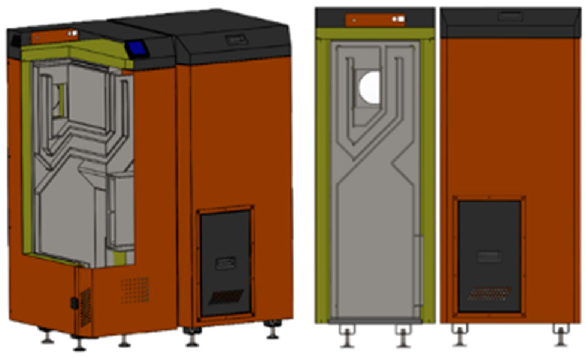
The tested biomass heating boiler (BIOVERT 21, automatic fuel feed) of the nominal power output of 21 kW was manufactured by Walendowscy, Pleszew, Poland (Figure 2). The heating boiler was fueled with biomass pellets with a minimum grain size of 5 mm, operating in the power range of 6.3 to 21.0 kW. The boiler met the fifth class requirements, according to the PN-EN 303-5:2021-09 [53,54,55] standard. A microchip controller governed the operation of the heating boiler. The boiler was fitted with a standard combustion chamber. For the operation with the nominal power setting (21 kW), the recorded fuel consumption was approximately 2.53 kg·h−1, and the intake air demand was recorded at approximately 18.94 m3·h−1. For the operation with the minimum power setting (6.3 kW), the fuel consumption was approximately 0.75 kg·h−1, and the intake air demand was approximately 5.68 m3·h−1. Figure 2 presents the tested object [56].

2.2. Flue Gas Distribution Valve

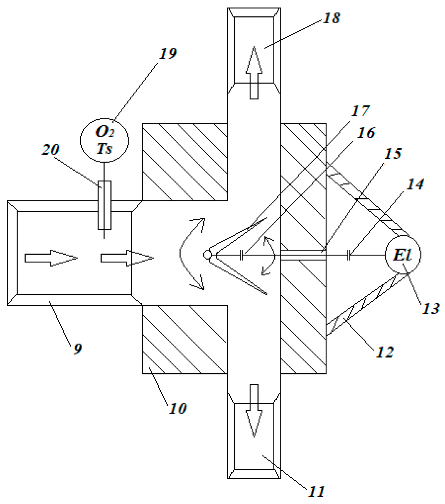
The proprietary flue gas recirculation system for biomass-fueled heating boilers has an adjustable flue gas distribution valve fitted in the boiler conduit. The flue gas distribution valve is equipped with a temperature and oxygen level sensor. The distribution valve is connected to the tall flue and the flue gas return duct. At the end of the return duct, a fan is fitted, reintroducing the flue gas to the combustion chamber above the combusted fuel. The flue gas distribution valve has an intake duct permanently fixed in the valve body which also houses two flue gas ducts: a flue gas return duct, leading to the boiler, and the proper flue duct. An electric motor is attached to the valve body, with a clip driving the geared propeller shaft, passing through an airtight sleeve and connecting with the differential gear used for opening/closing the flue gas ducts when the flue gas distributor is active. The opening angle of the distributor is set based on the flue gas temperature and the level of oxygen in the flue gas, as sensed by the temperature and oxygen level sensors fitted inside the flue gas intake through an airtight sleeve connected with the valve controller.
The recirculation of the flue gas is performed in the range of 0% to 100% of the fresh mass flow of flue gas through an adjustable flue gas distribution valve. The adjustment of the recirculation is based on a continuous measurement of the flue gas temperature and the level of oxygen by the measuring probe, and the results of the measurements enable the control of the distributor opening between 0% and 100% (directing the gas either for recirculation or to the flue). The recirculation of the flue gas generated from the combustion of biomass is possible in the excess air coefficient range of λ = 1.0–4.5, with a simultaneous recirculation of 0% to 100% of the fresh flue gas mass flow. The distribution valve is presented in Figure 3 (Pat. 243395).

2.3. Chemical Parameters of the Fuel

The biomass used in the tests (pinewood and beechwood pellets) was subjected to a technical analysis according to the standard [57,58,59,60,61]. The results of the analysis of biomass types and their higher caloric value (Qs) and lower calorific value (Qi) are presented in Table 2.

2.4. Emission Measurement Devices

The measurements were carried out with the use of portable exhaust gas analyzers fitted with electrochemical measuring cells. The first device was a Testo 350-S (Testo SE & Co. kGaA, Titisee-Neustadt, Germany) in a two-component configuration (controller and analyzer). The analyzer was fitted with an O2 sensing cell with a volume measurement range of 0–25% and an error margin of ±0.8%, which allowed the level of oxygen in the flue gas and H2 sensing cell to be recorded in the measurement range of 0–1000 ppm and with a margin of error of ±0.5 ppm. The Testo 350-S was fitted with an NO sensing cell with a measurement range of 0–3000 ppm and a margin of error of ±1.5 ppm. Additionally, the temperature of the flue gas was measured to an accuracy of ±1 °C.
The other device used in the tests was a Testo 380 particle analyzer (Testo SE & Co. kGaA, Titisee-Neustadt, Germany) coupled with a Testo 330-2 LL flue gas analyzer (Testo SE & Co. kGaA, Titisee-Neustadt, Germany), serving the purpose of controllers equipped with a display. The Testo 380 was used to measure particulate matter within the range of 0–300 mg/m3 and with a margin of error of ±5 mg/m3. The use of both devices at the same time, in the form of a combined unit, allowed the authors to measure both the concentration of carbon monoxide (CO) (0–8000 ppm), with a margin of error of ±10 ppm for the measure point (0–200 ppm) and ±20 ppm for measure point (201–2000 ppm), and the concentration of nitrogen oxides (NOx) (0–3000 ppm) with a margin of error of ±5 ppm (0–100 ppm) [62]. Figure 4 presents the aforementioned measurement devices.

3. Results and Discussion

The analysis of individual flue gas components (NOx, PM and CO) was ordered according to the boiler power setting, type of fuel and the flue gas recirculation rate ‘r’. The emissions of individual flue gas components were as follows:
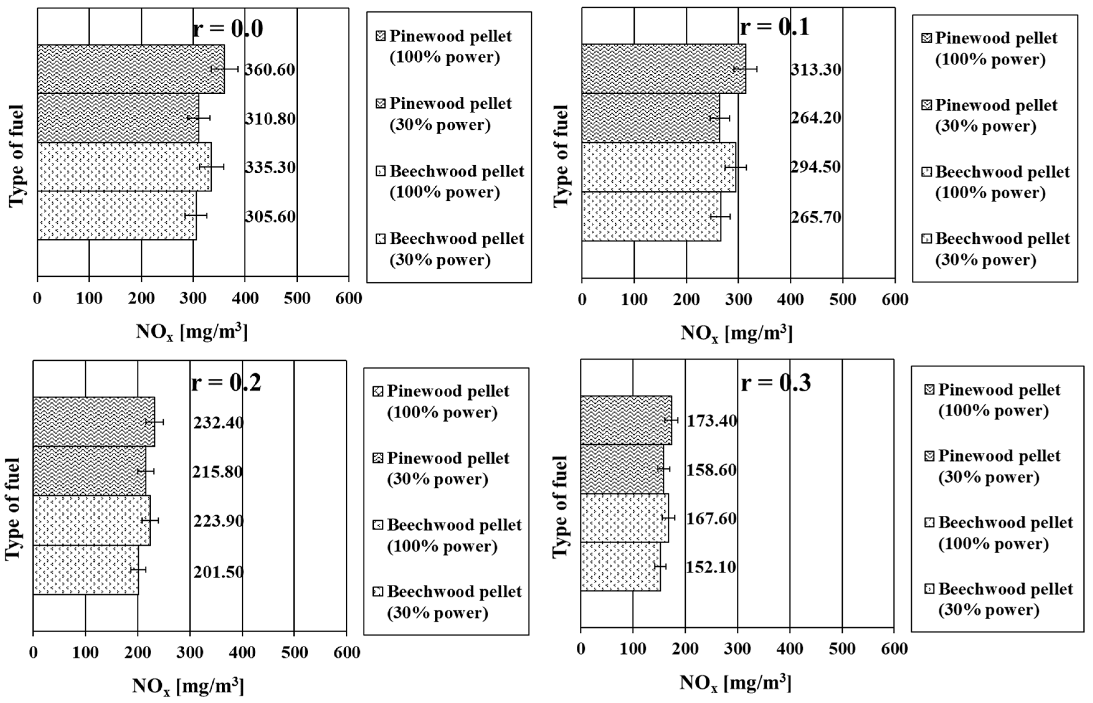
The content of NOx in the flue gas, for the recirculation rate r = 0.0 and the boiler power settings of 100% and 30%, were 360.60 mg/m3 and 310.80 mg/m3 for the pinewood pellets and 335.30 mg/m3 and 305.60 mg/m3 for the beechwood pellets, respectively. The values obtained for the lower power setting of the boiler are clearly lower for both types of biomass; yet, we may observe a greater disproportion for the measurements performed for the pinewood pellets.
For the recirculation rate r = 0.1, the NOx level for the pinewood pellets was 313.30 mg/m3 (100% power setting) and 264.20 mg/m3 (30% power setting), while, for the beechwood pellets, these values were 294.50 mg/m3 and 265.70 mg/m3, respectively. We may observe the same relation as the one recorded at r = 0.0; however, the differences between the measured values for the same type of fuel were slightly reduced.
Increasing the recirculation rate to r = 0.2 resulted in a further reduction in the NOx values. For this measurement series, the content of nitrogen oxides for the pinewood pellets reached 232.40 mg/m3 for the power setting of 100% and 215.80 mg/m3 for the power setting of 30%. For the beechwood fuel, these values were 223.90 mg/m3 and 201.50 mg/m3, respectively. The differences between the values recorded for the same fuel diminished in both cases by almost half of the value of their previous difference.
For the recirculation rate r = 0.3, the following values were measured: the NOx levels for pinewood pellets, at the 100% and 30% power settings, were 173.40 mg/m3 and 158.60 mg/m3, while, for the beechwood pellets, these values were 167.60 mg/m3 and 152.10 mg/m3. Despite the fact that, for the same type of fuel, the disproportions between the two values, occurring due to the power setting of the boiler, were diminishing, the original trend is still observable.
For all recirculation rates, we may observe a relation between the boiler power settings and the level of NOx in the flue gas—a lower power setting resulted in a lower NOx content in the flue gas. The content of NOx was reduced gradually as the recirculation rate increased, similarly to the disproportions between the measurements for a given fuel recorded for different boiler power settings (reduced not only in terms of quantity but also in terms of % content). The data collected during the tests performed on the pinewood fuel for each measurement were characterized by higher values of the analyzed parameter, compared to the values obtained under the same conditions for the beechwood fuel. Figure 5 presents the changes in NOx emissions in relation to the type of fuel, power setting and flue gas recirculation rate.
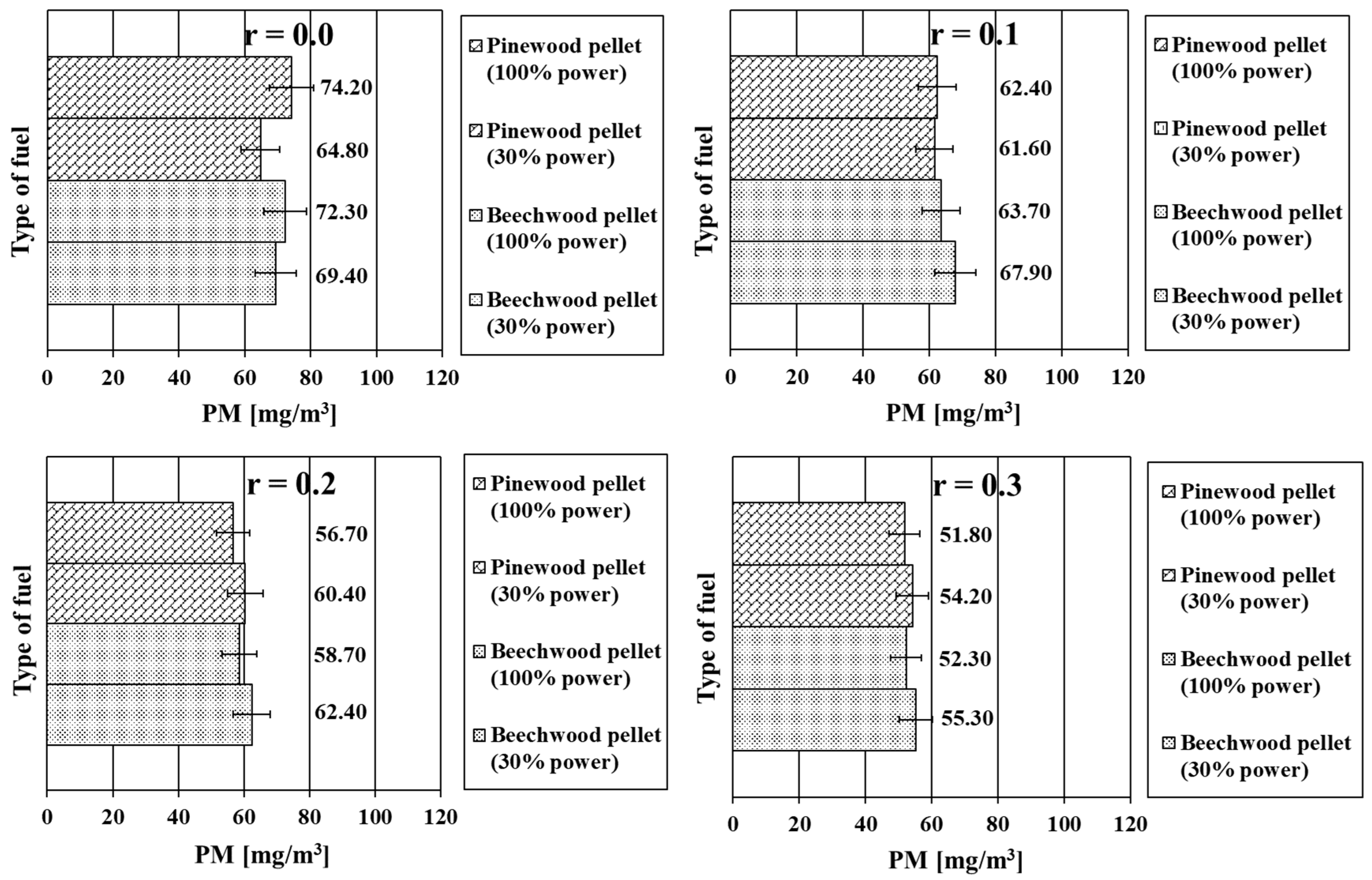
When analyzing the changes in the emission of PM, the authors observed that, for a recirculation rate of r = 0.0 (with pinewood pellets), the values were 74.20 mg/m3 for the 100% power setting and 64.80 mg/m3 for the 30% power setting. A similar relation was observed for the beechwood pellets, where the PM values were 72.30 mg/m3 and 69.40 mg/m3, respectively. The analysis of these values allows for the conclusion that lower power settings resulted in lower PM parameters. Additionally, the beechwood fuel exhibited a lower decrease in these values compared to pinewood.
For a recirculation rate of r = 0.1, the values obtained for the pinewood pellets were 62.40 mg/m3 for the 100% power setting and 61.60 mg/m3 for the power setting reduced to 30%. Also, in this case, we may observe a diminishing trend of the PM parameter as the power setting of the boilers was decreased; however, for higher recirculation rates, the change was less significant (0.8 mg/m3). The beechwood fuel exhibited an opposite and contrary trend: the measured value of PM was 63.70 mg/m3 for the power setting of 100% and 67.90 mg/m3 for the setting of 30%. Reducing the power setting resulted in an increased PM parameter.
When the recirculation rate gradually increased to r = 0.2, the PM values reached 56.70 mg/m3 for the 100% power setting and 60.40 mg/m3 for the 30% power setting (for pinewood). In the case of the beechwood pellets, these values were 58.70 mg/m3 and 62.40 mg/m3, respectively. For the variable ‘r’ analyzed during the measurements, we could observe a trend already recorded during earlier measurements: the relation was based on the increasing PM level with the reduced power setting.
This correlation was also reflected in the values collected in the measurements when the recirculation rate was r = 0.3. In this measurement trial, the values measured for pinewood were 51.80 mg/m3 (with the 100% power setting) and 54.20 mg/m3 (with the 30% power setting). For the beechwood pellets, the values were 52.30 mg/m3 and 55.30 mg/m3.
We may therefore conclude the zero recirculation rate was characterized by the highest recorded PM values out of all the measurement trials. A drop in these values, along with the increase in the recirculation rate, was observed not only for both types of fuel but also for both analyzed boiler power settings. This relationship, however, connected to the correlation of the PM level and the recirculation rate; although, at r = 0.0, a higher power setting denoted greater emissions of PM. For r = 0.1, the beechwood fuel began to show an increasing trend as the ‘r’ parameter grew and, from r = 0.2 onward, both fuels had higher PM values obtained at lower power settings. The change in the emission of PM, depending on the type of fuel, power setting and recirculation rate, is shown in Figure 6.
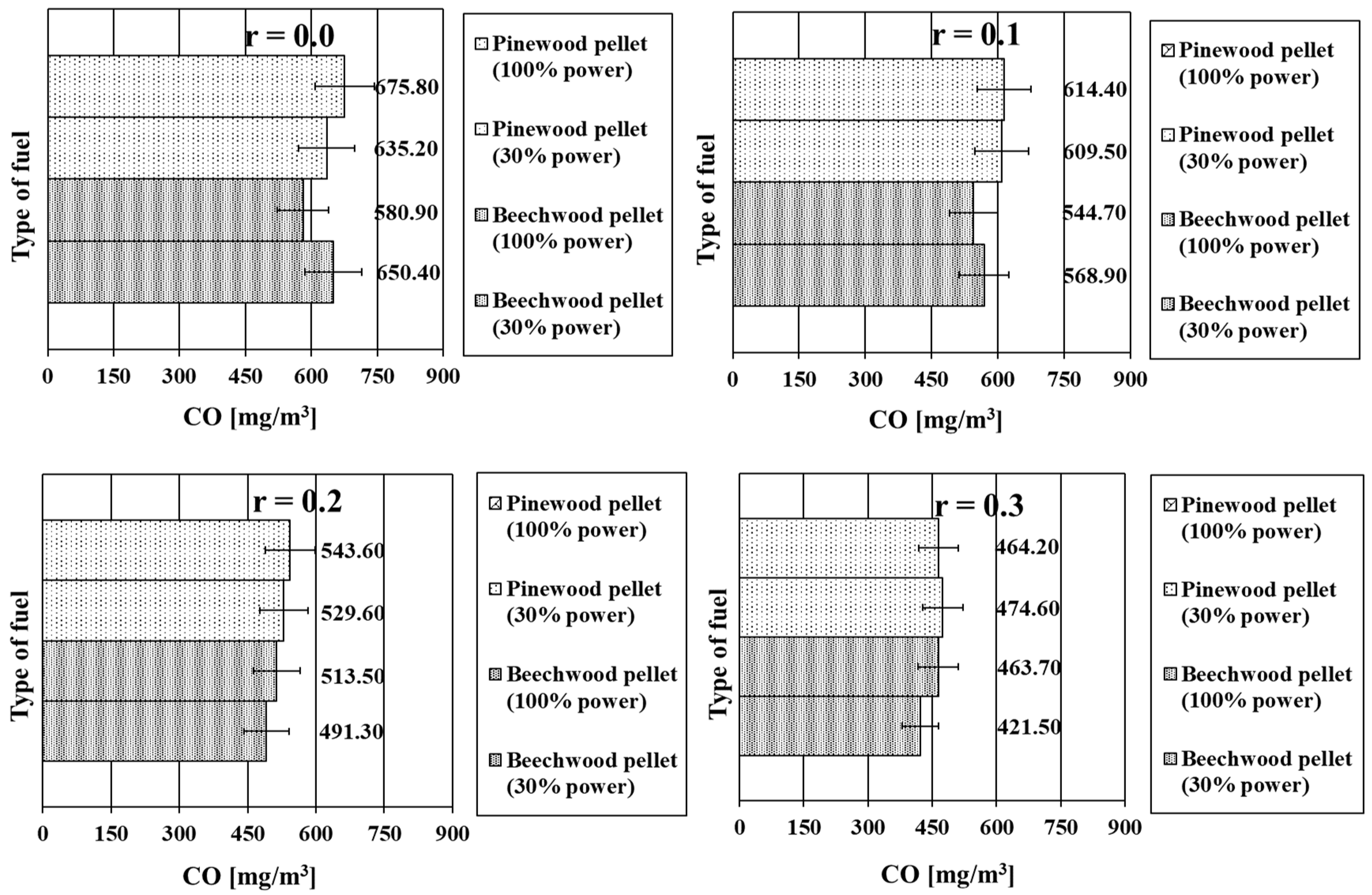
In the case of the emission of CO with a recirculation rate of r = 0.0, the recorded value oscillated around 580–680 mg/m3. For the pinewood fuel and the 100% power setting, the value of CO was 675.80 mg/m3, and, for the 30% power setting, it was 635.20 mg/m3. For the beechwood fuel, the values were 580.90 mg/m3 and 650.40 mg/m3. Collating the values allowed us to observe the differences in the correlations of the CO level and the power setting of the boiler, depending on the type of investigated fuel—for the pinewood pellets, the values were convergent, and, for the beechwood pellets, they were inversely proportional.
Even though the recirculation rate r = 0.1 rendered similar relations, the differences between the measured values were significantly smaller. The pinewood-based fuel generated CO emissions of 614.40 mg/m3 for the 100% power setting and 609.50 mg/m3 for the 30% power setting, while, for the beechwood-based fuel, these values were 544.70 mg/m3 and 568.90 mg/m3, respectively. For both types of fuel, a noticeable drop in the emissions of CO in the flue gas was observed.
Increasing the recirculation rate to r = 0.2 resulted in values of 543.60 mg/m3 and 529.60 mg/m3 for pinewood and 513.50 mg/m3 and 491.30 mg/m3 for beechwood (for the 100% and 30% power settings, respectively). A comparison of the results indicates a decreasing trend in CO emissions in the flue gas at the same time, showing a relationship between the amount of generated CO and the power setting of the boiler: this time, the analyzed values decreased, in correlation with both analyzed fuel types.
For the highest recirculation rate, r = 0.3, the lowest values of CO emissions were recorded. The pinewood pellets generated 464.20 mg/m3 (100% power setting) and 474.60 mg/m3 (30% power setting). In the case of beechwood, the values were 463.70 mg/m3 and 421.50 mg/m3, respectively. However, in the case of the beechwood fuel, we could again observe lower CO values at the lower power setting of the boiler, and, for the pinewood pellets, at r = 0.3, higher CO levels were observed at the 30% power setting of the boiler.
For both fuel types under analysis, we may observe a significant drop in the content of CO in the flue gas, continuing along the increase in the recirculation rate ‘r’. However, the impact of the boiler power setting leads to different results. For pinewood, originally, the higher power setting resulted in an increased CO content in the flue gas. The disproportions between the 100% and 30% power settings gradually decreased as the recirculation rate increased from r = 0.1 to r = 0.2. For the highest investigated recirculation rate, r = 0.3, this relation differed: the lower power setting of the boiler was characterized by higher CO emissions. As for beechwood, we may observe a consistent drop in the CO values for both power settings. The decreasing process of this parameter continued much more rapidly for the lower power setting, which resulted in the reduction of the disproportion between r = 0.0 and r = 0.1, a change to the original relationship for r = 0.2, and finally the obtaining of the highest difference between the measurements for the 100% and the 30% power settings at r = 0.3. The CO emission parameters are presented in Figure 7.
According to the standard [53], a fifth class, eco-design-compliant biomass-burning boiler should have the following emission levels: NOx emissions below 200 mg/m3, CO emissions below 500 mg/m3 and PM emissions below 40 mg/m3. The results for individual harmful components were averaged from all fuels and performed tests within a given test configuration. The results are shown in Figure 8. Additionally, the authors performed an approximation of the course of the function of emissions of a given harmful component. The approximation was performed for the second order multinomial function (due to this being the nearest representation of the actual course). The equation describing the course of the emission changes depending on the flue gas recirculation rate, and the sensitivity of this representation fell in the 99% percentile of representation sensitivity.
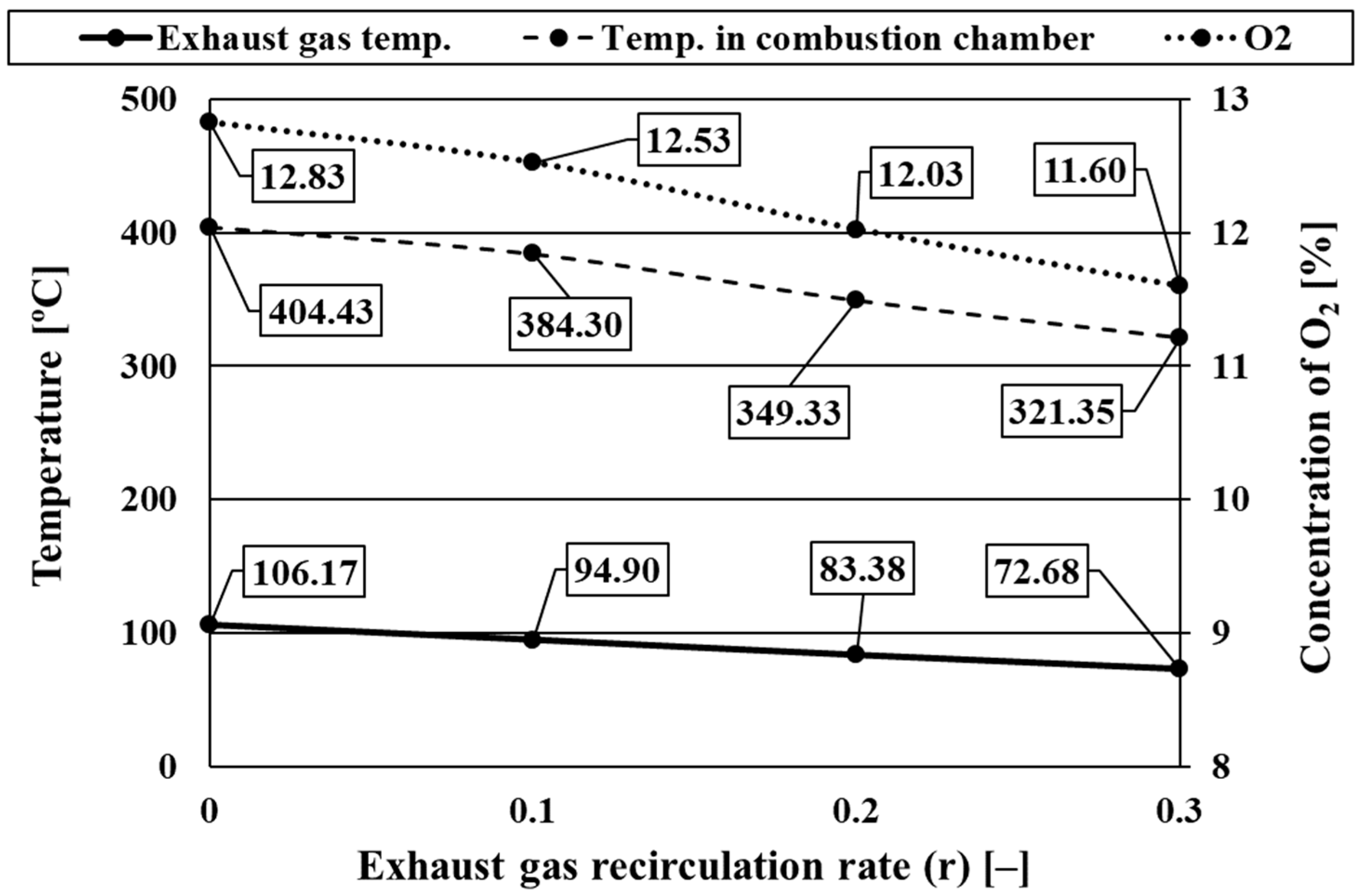
The averaged results for the flue gas temperature, the temperature inside the combustion chamber and the concentration of O2 in the flue gas are shown in Figure 9.
By synthesizing observations and conclusions from the conducted research and analyzing the literature [19,20,21,22,23,27,29,31,39,40,41,42,43,44,45,46,47,48,49,50,51,52] regarding flue gas recirculation in industrial combustion processes, the following points are observed:
The temperature to which the recirculated flue gases are heated should be higher than the initial temperature of the flue gases, in order to prevent the formation of thermal nitrogen oxides, mainly when temperature peaks appear (Tf < 1500 K);
The recirculation of flue gases at temperatures up to 1073 K should be carried out to prevent the local concentration of oxygen in the area of high-temperature combustion. In the developed flue gas distribution valve solution, when the recirculation rate ‘r’ is increased, the emissions of NOx, PM and CO decrease, and, at the same time, decreases in both the flue gas temperature and the temperature in the combustion chamber are observed. In the solution under consideration, the appearance of thermal and immediate nitrogen oxides is not visible, due to the use of precise regulation of the recirculation rate based on the oxygen content in the flue gases and their temperature;
The main problem in the case of flue gas recirculation systems used in industrial solutions is the occurrence of excessive CO and PM emissions during radical flue gas recirculation. In the case of high-temperature and flameless combustion, low NOx and CO emissions are observed only in the case of gaseous fuels. In the case of solid fuels, which include biomass, in the case of low-temperature combustion, typical of heating boilers, flameless combustion is impossible; therefore, from analyzing the obtained test results, it can be assumed that, for this group of devices, a regulated flue gas recirculation system, implemented by a system of valves with full automation control, is the right step for further research and industrial implementations;
Special attention should be paid to flue gas recirculation rates greater than r = 0.3 in the case of low-temperature biomass combustion in heating boilers, due to the close proximity of the flue gas dew point temperature, and the possibility of moisture condensation in the system recirculation channels. This problem may have the opposite effect than that intended and will manifest itself in a significant amount of carbon monoxide emissions, with an observed decline in nitrogen oxide emissions. More information on emissions during combustion in a humid atmosphere can be found in [30].

4. Conclusions

Based on the observations made during the analysis of the impact of the flue gas recirculation rate on the values of PM, we may observe that the increase in the former parameter results in the regression of the latter. At a recirculation rate of zero, the highest PM values were recorded, which gradually decreased as the ‘r’ parameter grew. Even though this trend was clear for all measurement trials, changes in the relations between the PM values and the power setting of the boiler were observed—at r = 0.0, the higher power setting resulted in higher values of PM; at r = 0.1, beechwood started exhibiting increasing PM emissions as the ‘r’ parameter increased; and, from r = 0.2 upward, both types of fuel generated higher PM values, which were obtained at the lower power setting of the boiler.
The analysis of the content of CO in the flue gas has shown a significant drop with an increased recirculation rate. Also, in this case, despite the maintained correlation for all measurements, gradual changes occurred, which were related to the impact of the power setting of the boiler on the results. In the case of pinewood, for the first measurements, the higher power setting resulted in an increased value of CO. The increase in the recirculation rate to r = 0.1 and r = 0.2 resulted in a reduction in the recorded disproportion between the 100% and the 30% power setting. Only at r = 0.3 did this relationship begin to differ—the lower power setting of the boiler resulted in a higher value of CO. For beechwood, we observed a consistent drop in the value of CO for both power settings. The regression of this parameter took place more rapidly for the lower power setting, which resulted in the reduction of the disproportion between r = 0.0 and r = 0.1, a change to the original relationship for r = 0.2, and, consequently, the highest difference between the values for the 100% and the 30% power settings of the boiler at r = 0.3.
All flue gas recirculation rates were characterized by the same relations between the power setting of the boiler and the emission of NOx: a lower setting of the former resulted in lower values of the latter. The content of NOx decreased gradually as the recirculation rate increased. The reduction in the disproportion between the measurements for a given fuel at different power settings of the boiler (reduced not only in terms of quantity but also in % content) occurred in a similar way. The measurements performed for beechwood in each measurement trial had lower values than those recorded for pinewood under the same combustion conditions.
In conclusion, the obtained research results for the industrial application of the authors’ exhaust gas recirculation system for biomass heating boilers show the possibility of reducing the emissions of NOx and other harmful substances (CO and PM) and reducing the emission of waste heat in the form of hot flue gases, which, in the case of using this technology in boilers, should result in an increase in the efficiency of the device and also an improvement in air quality [32,36].

Author Contributions

Conceptualization: B.C. and R.U.; methodology: B.C.; software: B.C.; validation: B.C., R.U. and D.K.; formal analysis: B.C., R.U. and D.K.; investigation: B.C., R.U. and Z.N.; resources: B.C., R.U. and D.K.; data curation: B.C., R.U. and D.K.; writing—original draft preparation: B.C., R.U. and D.K.; writing—review and editing: B.C., R.U. and D.K.; visualization: B.C., R.U. and Z.N.; supervision: B.C., R.U. and Z.N.; project administration: B.C. and Z.N.; funding acquisition: B.C., R.U. and Z.N. All authors have read and agreed to the published version of the manuscript.

Funding

The research was financed by the Poznan University of Technology’s financial resources for statutory activity. Number of project: 0712/SBAD/5224. The publication was financed by the University of Kalisz’s financial resources.

Institutional Review Board Statement

Not applicable.

Informed Consent Statement

Not applicable.

Data Availability Statement

Data are contained within the article.

Conflicts of Interest

The authors declare no conflicts of interest.

Nomenclature

COcarbon monoxide, colorless oxidation
CO2carbon dioxide
EECexcess enthalpy combustion
EGRexhaust gas recirculation
FGRflue gas recirculation
FLOXflameless oxidation
GAFTgasdynamic abated flame temperature
HTAChigh temperature air combustion
NOnitric oxide
NO2nitrogen dioxide
N2Onitrous oxide
N2O3dinitrogen trioxide
N2O5dinitrogen pentoxide
NOxnitrogen oxides
O2oxygen
PMparticulate matters
SGRsemilar gas recycling
Tfexhaust gas temperature

References

  1. Judt, W.; Ciupek, B.; Urbaniak, R. Numerical study of a heat transfer process in a low power heating boiler equipped with afterburning chamber. Energy 2020, 196, 117093. [Google Scholar] [CrossRef]
  2. Ciupek, B.; Judt, W.; Urbaniak, R.; Kłosowiak, R. The emission of carbon monoxide and nitrogen oxides from boilers supplied by a pellet under the influence of changes in the air-fuel equivalence ratio. J. Ecol. Eng. 2019, 20, 34–38. [Google Scholar] [CrossRef] [PubMed]
  3. Ciupek, B.; Janeba-Bartoszewicz, E.; Urbaniak, R. Effect of fineness and increased humidity of carbonaceous fuels on the chemical composition of exhaust gases. Chem. Ind. 2019, 1, 8. [Google Scholar] [CrossRef]
  4. Ciupek, B. Study on hard coal combustion in heating boilers equipped with a steam-fed afterburning chamber. Chem. Ind. 2020, 99, 8. [Google Scholar] [CrossRef]
  5. Szufa, S.; Wielgosiński, G.; Piersa, P.; Czerwińska, J.; Dzikuć, M.; Adrian, Ł.; Lewandowska, W.; Marczak, M. Torrefaction of Straw from Oats and Maize for Use as a Fuel and Additive to Organic Fertilizers—TGA Analysis, Kinetics as Products for Agricultural Purposes. Energies 2020, 13, 2064. [Google Scholar] [CrossRef]
  6. Dudek, M.; Adamczyk, B.; Grzywacz, P.; Lach, R.; Sitarz, M.; Leśniak, M.; Gajek, M.; Mech, K.; Wilk, M.; Rapacz-Kmita, A.; et al. The Utilisation of Solid Fuels Derived from Waste Pistachio Shells in Direct Carbon Solid Oxide Fuel Cells. Materials 2021, 14, 6755. [Google Scholar] [CrossRef] [PubMed]
  7. Godzisz, K.; Dzikuć, M.; Kułyk, P.; Piwowar, A.; Kuryło, P.; Szufa, S. Selected Determinants of Sustainable Transport in the Context of the Development of a Low-Carbon Economy in Poland. Energies 2021, 14, 5418. [Google Scholar] [CrossRef]
  8. Wilk, M.; Gajek, M.; Śliz, M.; Czerwińska, K.; Lombardi, L. Hydrothermal Carbonization Process of Digestate from Sewage Sludge: Chemical and Physical Properties of Hydrochar in Terms of Energy Application. Energies 2022, 15, 6499. [Google Scholar] [CrossRef]
  9. Zardzewiały, M.; Bajcar, M.; Saletnik, B.; Puchalski, C.; Gorzelany, J. Biomass from Green Areas and Its Use for Energy Purposes. Appl. Sci. 2023, 13, 6517. [Google Scholar] [CrossRef]
  10. Ciupek, B.; Gołoś, K. Concentration of Nitrogen Oxides When Burning Wood Pellets of Various Origins. J. Ecol. Eng. 2020, 21, 229–233. [Google Scholar] [CrossRef]
  11. Kačániová, M.; Vukovic, N.L.; Čmiková, N.; Galovičová, L.; Schwarzová, M.; Šimora, V.; Kowalczewski, P.Ł.; Kluz, M.I.; Puchalski, C.; Bakay, L.; et al. Salvia sclarea Essential Oil Chemical Composition and Biological Activities. Int. J. Mol. Sci. 2023, 24, 5179. [Google Scholar] [CrossRef] [PubMed]
  12. Aleksiejczuk, A.; Teleszewski, T.J. Estimation of Sulfur Dioxide Emissions in an Automatic Boiler with a Retort Burner for Coal and Biomass in a Single-Family House Based on the Measurement of the Heat Consumed. Environ. Sci. Proc. 2022, 18, 10. [Google Scholar] [CrossRef]
  13. Kraszkiewicz, A.; Przywara, A.; Parafiniuk, S. Emission of Nitric Oxide during the Combustion of Various Forms of Solid Biofuels in a Low-Power Heating Device. Energies 2022, 15, 5960. [Google Scholar] [CrossRef]
  14. Kraszkiewicz, A.; Przywara, A.; Anifantis, A.S. Impact of Ignition Technique on Pollutants Emission during the Combustion of Selected Solid Biofuels. Energies 2020, 13, 2664. [Google Scholar] [CrossRef]
  15. Graham, S.; Ogunfayo, I.; Hall, M.R.; Snape, C.; Quick, W.; Weatherstone, S.; Eastwick, C. Changes in mechanical properties of wood pellets during artificial degradation in a laboratory environment. Fuel Process. Technol. 2016, 148, 395–402. [Google Scholar] [CrossRef]
  16. Obernberger, I.; Brunner, T.; Bärnthaler, G. Chemical properties of solid biofuels–significance and impact. Biomass Bioenergy 2006, 30, 973–982. [Google Scholar] [CrossRef]
  17. García, R.; Pizarro, C.; Lavín, A.G.; Bueno, J.L. Spanish biofuels heating value estimation. Part II: Proximate analysis data. Fuel 2014, 117, 1139–1147. [Google Scholar] [CrossRef]
  18. Boman, C.; Pettersson, E.; Westerholm, R.; Boström, D.; Nordin, A. Stove performance and emission characteristic in residential wood log and pellet combustion. Part 1: Pellet stoves. Energy Fuels 2011, 25, 307–314. [Google Scholar] [CrossRef]
  19. Liu, H.; Chaney, J.; Li, J.; Sun, C. Control of NOx emissions of a domestic/small-scale biomass pellet boiler by air staging. Fuel 2013, 103, 792–798. [Google Scholar] [CrossRef]
  20. Bhattu, D.; Zotter, P.; Zhou, J.; Stefenelli, G.; Klein, F.; Bertrand, A.; Temime-Roussel, B.; Marchand, N.; Slowik, J.G.; Baltensperger, U.; et al. Effect of stove technology and combustion conditions on gas and particulate emissions from residential biomass combustion. Environ. Sci. Technol. 2019, 53, 2209–2219. [Google Scholar] [CrossRef]
  21. Fachinger, F.; Drewnick, F.; Gieré, R.; Borrmann, S. How the user can influence particulate emissions from residential wood and pellet stoves: Emission factors for different fuels and burning conditions. Atmos. Environ. 2017, 158, 216–226. [Google Scholar] [CrossRef]
  22. Mitchell, E.J.S.; Lea-Langton, A.R.; Jones, J.M.; Williams, A.; Layden, P.; Johnson, R. The impact of fuel properties on the emissions from the combustion of biomass and other solid fuels in a fixed bed domestic stove. Fuel Process. Technol. 2016, 142, 115–123. [Google Scholar] [CrossRef]
  23. Houshfar, E.; Skreiberg, Ø.; Løvås, T.; Todorovic, D.; Sorum, L. Effect of excess air ratio and temperature on NOx emission from grate combustion of biomass in the staged air combustion scenario. Energy Fuels 2011, 25, 4643–4654. [Google Scholar] [CrossRef]
  24. Malico, I.; Pereira, R.N.; Gonçalves, A.C.; Sousa, A.M.O. Current status and future perspectives for energy production from solid biomass in the European industry. Renew. Sustain. Energy Rev. 2019, 112, 960–977. [Google Scholar] [CrossRef]
  25. Bogusz, M.; Matysik-Pejas, R.; Krasnodębski, A.; Dziekański, P. The Concept of Zero Waste in the Context of Supporting Environmental Protection by Consumers. Energies 2021, 14, 5964. [Google Scholar] [CrossRef]
  26. Ozgen, S.; Cernuschi, S.; Caserini, S. An overview of nitrogen oxides emissions from biomass combustion for domestic heat production. Renew. Sustain. Energy Rev. 2021, 135, 110113. [Google Scholar] [CrossRef]
  27. Nussbaumer, T. Combustion and Co-combustion of Biomass: Fundamentals, Technologies, and Primary Measures for Emission Reduction. Energy Fuels 2003, 17, 1510–1521. [Google Scholar] [CrossRef]
  28. Demirbas, A. Potential applications of renewable energy sources, biomass combustion problems in boiler power systems and combustion related environmental issues. Prog. Energy Combust. Sci. 2005, 31, 171–192. [Google Scholar] [CrossRef]
  29. Speth, K.; Murer, M.; Spliethoff, H. Experimental investigation of nitrogen species distribution in wood combustion and their influence on NOx reduction by combining air staging and ammonia injection. Energy Fuels 2016, 30, 5816–5824. [Google Scholar] [CrossRef]
  30. Ciupek, B.; Gołoś, K.; Jankowski, R.; Nadolny, Z. Effect of Hard Coal Combustion in Water Steam Environment on Chemical Composition of Exhaust Gases. Energies 2021, 14, 6530. [Google Scholar] [CrossRef]
  31. Khodaei, H.; Guzzomi, F.; Yeoh, G.H.; Regueiro, A.; Pati, D. An experimental study into the effect of air staging distribution and position on emissions in a laboratory scale biomass combustor. Energy 2016, 118, 1243–1255. [Google Scholar] [CrossRef]
  32. Gołoś, K.; Ciupek, B.; Judt, W.; Urbaniak, R. Impact of replacement of solid fuel heating boilers on air quality in Poland in 2000–2020. Chem. Ind. 2021, 100, 96–99. [Google Scholar] [CrossRef]
  33. Kurc, B.; Lijewski, P.; Rymaniak, Ł.; Fuć, P.; Pigłowska, M.; Urbaniak, R.; Ciupek, B. High-Energy Solid Fuel Obtained from Carbonized Rice Starch. Energies 2020, 13, 4096. [Google Scholar] [CrossRef]
  34. Krzyżaniak, M.; Stolarski, M.J.; Szczukowski, S.; Tworkowski, J. Thermophysical and chemical properties of biomass obtained from willow coppice cultivated in one- and three-year rotation cycles. J. Elem. 2014, 1, 161–175. [Google Scholar] [CrossRef]
  35. Obaidullah, M.; Bram, S.; Verma, V.K.; De Ruyck, J. A Review on Particle Emissions from Small Scale Biomass Combustion. Int. J. Renew. Energy Res. 2012, 2, 147–159. [Google Scholar]
  36. Ciupek, B.; Judt, W.; Gołoś, K.; Urbaniak, R. Analysis of Low-Power Boilers Work on Real Heat Loads: A Case of Poland. Energies 2021, 14, 3101. [Google Scholar] [CrossRef]
  37. Pełka, G.; Wygoda, M.; Lubo’n, W.; Pachytel, P.; Jachimowski, A.; Paprocki, M.; Wyczesany, P.; Kotyza, J. Analysis of the Efficiency of a Batch Boiler and Emissions of Harmful Substances during Combustion of Various Types of Wood. Energies 2021, 14, 6783. [Google Scholar] [CrossRef]
  38. Lisowski, A.; Dąbrowska-Salwin, M.; Ostrowska-Ligęza, E.; Nawrocka, A.; Stasiak, M.; Świętochowski, A.; Klonowski, K.; Sypuła, M.; Lisowska, B. Effects of the biomass moisture content and pelleting temperature on the pressure-induced agglomeration process. Biomass Bioenergy 2017, 107, 376–383. [Google Scholar] [CrossRef]
  39. Andersen, V.; Solheim, I.; Gaertner, H.; Sægrov-Sorte, B.; Einarsrud, K.E.; Tranell, G. Pilot-Scale Test of Flue Gas Recirculation for The Silicon Process. J. Sustain. Metall. 2023, 9, 81–92. [Google Scholar] [CrossRef]
  40. Kim, H.K.; Kim, Y.; Lee, S.M.; Ahn, K.Y. NO reduction in 0.03–0.2 MW oxy-fuel combustor using flue gas recirculation technology. Proc. Combust. Inst. 2007, 31, 3377–3384. [Google Scholar] [CrossRef]
  41. Fan, X.; Wong, G.; Gan, M.; Chen, X.; Yu, Z.; Ji, Z. Establishment of refined sintering flue gas recirculation patterns for gas pollutant reduction and waste heat recycling. J. Clean. Prod. 2019, 235, 1549–6526. [Google Scholar] [CrossRef]
  42. Cholewiński, M.; Pospolita, W. Application of Biomass Swirl Burners in High-Power Boilers. Tech. Issues 2016, 2, 3–10. [Google Scholar]
  43. Ladommatos, N.; Abdelhalim, S.; Zhao, H. The effects of exhaust gas recirculation on diesel combustion and emissions. Int. J. Engine Res. 2000, 1, 107–126. [Google Scholar] [CrossRef]
  44. Abd-Alla, G.H. Using exhaust gas recirculation in internal combustion engines: A review. Energy Convers. Manag. 2002, 43, 1027–1042. [Google Scholar] [CrossRef]
  45. Wei, H.; Zhu, T.; Shu, G.; Tan, L.; Wang, Y. Gasoline engine exhaust gas recirculation—A review. Appl. Energy 2012, 99, 534–544. [Google Scholar] [CrossRef]
  46. ElKady, A.M.; Evulet, A.; Brand, A.; Ursin, T.P.; Lynghjem, A. Application of Exhaust Gas Recirculation in a DLN F-Class Combustion System for Postcombustion Carbon Capture. J. Eng. Gas Turbines Power 2009, 131, 034505. [Google Scholar] [CrossRef]
  47. Cairns, A.; Blaxill, H. The Effects of Combined Internal and External Exhaust Gas Recirculation on Gasoline Controlled Auto-Ignition; SAE Technical Paper; SAE International: Warrendale, PA, USA, 2005. [Google Scholar]
  48. Guethe, F.; de la Cruz García, M.; Burdet, A. Flue Gas Recirculation in Gas Turbine: Investigation of Combustion Reactivity and NOX Emission. In Proceedings of the ASME Turbo Expo 2009: Power for Land, Sea, and Air. Volume 2: Combustion, Fuels and Emissions, Orlando, FL, USA, 8–12 June 2009; ASME: New York, NY, USA, 2009; pp. 179–191. [Google Scholar]
  49. Baltasar, J.; Carvalho, M.G.; Coelho, P.; Costa, M. Flue gas recirculation in a gas-fired laboratory furnace: Measurements and modelling. Fuel 1997, 76, 919–929. [Google Scholar] [CrossRef]
  50. Liuzzo, G.; Verdone, N.; Bravi, M. The benefits of flue gas recirculation in waste incineration. Waste Manag. 2007, 27, 106–116. [Google Scholar] [CrossRef]
  51. Diego, L.F.; de las Obras-Loscertales, M.; Rufas, A.; García-Labiano, F.; Gayán, P.; Abad, A.; Adánez, J. Pollutant emissions in a bubbling fluidized bed combustor working in oxy-fuel operating conditions: Effect of flue gas recirculation. Appl. Energy 2013, 102, 860–867. [Google Scholar] [CrossRef]
  52. Haryanto, A.; Hong, K.S. Modeling and simulation of an oxy-fuel combustion boiler system with flue gas recirculation. Comput. Chem. Eng. 2011, 35, 25–40. [Google Scholar] [CrossRef]
  53. EN 303-5:2012; Heating Boilers—Part 5: Heating Boilers for Solid Fuels, Manually and Auto-Matically Stocked, Nominal Heat Output of up to 500 kW—Terminology, Requirements, Testing and Marking. Polish Committee for Standardization: Warsaw, Poland, 2012.
  54. 2009/125/EC; Establishing a Framework for the Setting of Ecodesign Requirements for Energy-Related Products. European Parliament: Warsaw, Poland, 2009.
  55. 2015/1189; Implementing Directive 2009/125/EC of the European Parliament and of the Council with Regard to Ecodesign Requirements for Solid Fuel Boilers. Commision Regulation (EU): Brussels, Belgium, 2015.
  56. Available online: https://www.walsc.pl/kociol-klasy-5,12 (accessed on 3 November 2023).
  57. EN ISO 18122:2016; Solid Biofuels—Determination of Ash Content. Polish Committee for Standardization: Warsaw, Poland, 2016.
  58. EN ISO 18125:2017; Solid Biofuels. Determination of Calorific Value. Polish Committee for Standardization: Warsaw, Poland, 2017.
  59. EN ISO 16127:2012; Solid Biofuels. Determination of Length and Diameter of Pellets. Polish Committee for Standardization: Warsaw, Poland, 2012.
  60. EN ISO 18134-2:2017; Solid Biofuels. Determination of Moisture Content. Oven Dry Method. Polish Committee for Standardization: Warsaw, Poland, 2017.
  61. EN ISO 18123:2015; Solid Biofuels. Determination of Volatile Matter. Polish Committee for Standardization: Warsaw, Poland, 2015.
  62. Available online: https://www.testo.com (accessed on 3 November 2023).
Figure 1. Diagram of the test stand: 1—solid fuel heating boiler, 2—boiler duct, 3—boiler flue, 4—flue gas distribution valve, 5—exhaust gas collector, 6—fan, 7—flue duct, and 8—boiler combustion chamber.
Energies 17 00259 g001
Figure 2. BIOVER 21 boiler used in the tests.
Energies 17 00259 g002
Figure 3. Diagram of the flue gas distribution valve: 9—flue gas intake duct, 10—valve housing, 11—boiler return duct, 12—clamp, 13—electric motor, 14—gearbox, 15—sleeve, 16—differential gear, 17—flue gas distributor, 18—flue duct, 19—probe measuring the flue gas temperature and the oxygen content, and 20—sleeve.
Energies 17 00259 g003
Figure 4. Flue gas analyzers used in the tests. On the left: Testo 350 S; on the right: Testo 380 and Testo 330-2 LL.
Energies 17 00259 g004
Figure 5. NOx emissions, in relation to the flue gas recirculation rate.
Energies 17 00259 g005
Figure 6. PM emissions, in relation to the flue gas recirculation rate.
Energies 17 00259 g006
Figure 7. CO emissions, according to the flue gas recirculation rate.
Energies 17 00259 g007
Figure 8. Averaged emissions of NOx, CO and PM for a given recirculation rate, ‘r’.
Energies 17 00259 g008
Figure 9. Averaged flue gas temperature, combustion chamber temperature and concentration of O2 for a given recirculation rate, ‘r’.
Energies 17 00259 g009
Table 1. Program of the conducted research.
Stage of TestingType of BoilerPower SettingType of Fuel
(Pellets)
Exhaust Gas
Recirculation Rate
1.BIOVERT 21100%pinewoodr = 0.0 V ˙ ret = 0.00  [m3·h−1]
2.beechwood
3.30%pinewood
4.beechwood
5.100%pinewoodr = 0.1 V ˙ ret = 1.95  [m3·h−1]
6.beechwood
7.30%pinewood V ˙ ret = 0.75  [m3·h−1]
8.beechwood
9.100%pinewoodr = 0.2 V ˙ ret = 3.58  [m3·h−1]
10.beechwood
11.30%pinewood V ˙ ret = 1.37  [m3·h−1]
12.beechwood
13.100%pinewoodr = 0.3 V ˙ ret = 4.96  [m3·h−1]
14.beechwood
15.30%pinewood V ˙ ret = 1.89  [m3·h−1]
16.beechwood
Table 2. Analysis of the biomass used during the research.
Type of MeasurementPinewood PelletsBeechwood Pellets
Hygroscopic moisture content (Wh) %1.933.63
Excess moisture content (Wex) %3.146.61
Total moisture content (Wt) %5.0010.00
Volatile matter %73.6177.53
Ash content %0.470.41
C %54.7452.19
S %0.090.08
H2 %4.974.77
N2 %0.190.82
O2 %34.5431.73
High calorific value (Qs) MJ/kg14.9317.38
Low calorific value (Qi) MJ/kg14.3216.06
Disclaimer/Publisher’s Note: The statements, opinions and data contained in all publications are solely those of the individual author(s) and contributor(s) and not of MDPI and/or the editor(s). MDPI and/or the editor(s) disclaim responsibility for any injury to people or property resulting from any ideas, methods, instructions or products referred to in the content.