Abstract
A full electrification of many local railway lines is often not feasible or sustainable in terms of construction and maintenance costs or alternatively for the presence of additional constraints and limitations deriving from environmental or infrastructural limitations. Battery Operated or other kind of hybrid solutions powertrains are currently proposed as sustainable alternatives to Internal combustion engines for the propulsion of rolling stock on not electrified lines. In this work, authors propose the adoption of a partial electrification of lines to assure higher performances and reliability of battery-operated rolling stock designed to be recharged and feed using standard technologies such as pantographs gathering power from suspended catenaries. This innovative solution is designed and sized for a vehicle inspired from an existing one and simulated for two different existing lines, also proposing an optimal distribution of electrified sections dedicated to train recharge. This Case Study is simulated considering some possible applications to some existing railway lines in Italy.
1. Introduction
About a half of European railway lines is not electrified [1]. Not electrified lines are quite common on railway networks of many countries such as Germany [2]. Not electrified lines are diffused also in many extra-European railway networks. This situation is justified by construction and maintenance costs of electrified lines which are not affordable for low traffic intensities. Electrification is also penalized by the orography of crossed territories and by the availability of infrastructures such as connections to power grids or to local energy sources.
Rolling stock for both passenger and freight service on not electrified lines is powered by internal combustion engines with Hydraulic or Electric transmission systems.
The substitution of ICEs (Internal Combustion Engines) with other electric power sources or storages is proposed to increase sustainability an environmental impact in terms of direct emissions of CO2. Also, a simple hybridization of a Diesel-Electric locomotive as investigated by Magelli [3] can reduce emissions.
Proposed alternatives [4] are electric storages such as batteries [5,6] or hybrid hydrogen fuel cell systems [7,8]. Both technologies are affected by limitations that have been studied in comparative studies such as the ones of Zenith [8] and Cole [9]. Conclusions of these comparative studies are affected by technological improvements of key components like batteries and fuel cells [10]. As investigated by Zhang [11], usage of hybrid hydrogen fuel cells is currently limited by their poor dynamical performances and reliability especially on partial loads.
Dynamical limitations of fuel cells are compensated adopting a power buffer.
As investigated by Fragiacomo [12], batteries, capacitors, or hybrid systems, can be employed as power buffers.
The small size of power buffers involves a limited or null application of regenerative braking that penalize the efficiency of the whole system especially for mission profiles with frequent decelerations or strong altitude gradients.
Commercial fuel cell trains, such as Alstom Coradia [13], currently exhibit a far higher autonomy respect to corresponding battery-operated solutions. A further increase of autonomy is limited by the current technology of pressurized hydrogen tanks whose maximum operating pressures cannot exceed 350–700 bar [14,15].
High energy consumptions needed to pressurize hydrogen penalize “from well to wheel” efficiency and sustainability [16].
Specific energy density of Batteries [17] adopted for railway applications is still low (less than 100–120 Wh/kg).
Performances of cells and batteries proposed for automotive market [18,19] are growing thanks to huge investments needed for a large-scale production so a rapid growth of energy density for batteries is expected (200–300% in the next 30 years).
Batteries are reversible storages that allow an extensive use of regenerative braking on railway vehicles. So, it can be concluded that in a short-medium term scenario battery operated rolling stock will be a valid and competitive solution for not electrified lines.
Partially electrified lines represent a quite common scenario of employment: a part of the mission is performed along a route for which cost of line electrification is tolerable while the remaining part of the mission is performed on a not electrified one.
This scenario has been studied since 2013 by Hoffrichter et al. [20] which proposed a multi-modal solution in which propulsion of electric unit is alternatively granted by diesel units or collected from the overhead line. Recent studies of Abdurahman [21] demonstrate that the environmental impact of battery-trains on partially electrified line can be more sustainable respect to conventional solutions.
In the last two-three years, multimodal trains have been proposed for different applications such as tramways, suburban [22] and conventional railways [23,24]; so this topic is still very important for the community of railway researchers.
In this work, author has proposed the design of a multimodal passenger BEMU (Battery Electric Multiple Unit) also introducing some criteria to optimize the distribution of electrified sections along the line. Aim of the work is to improve autonomy respect to expected mission profiles. For proposed BEMU a mountain line is investigated. A Line with appreciable slopes/elevation gradients is deliberately chosen to emphasize the importance of regenerative braking. Optimal location of recharging infrastructure along the line is also investigated.
The aim is to demonstrate that a proper synergic design of both BEMU and partially electrified lines can make this solution interesting and competitive even in a short-term scenario in which progress of storage technology is still modest.
A particular attention is focused on the following aspects which also represent the innovative and more significant contributions of this work:
- Investigated BEMU train is inspired to existing industrial products. These solutions are interesting for some applications such as local passenger lines. The considerations in terms of energy management control are introduced.
- The dynamic recharging of the onboard batteries is performed using a conventional railway pantograph under a standard 3 kV catenary. The whole system is designed and simulated considering the power and current limits imposed by current regulations [25].
- The proposed solutions are verified by considering the stress on mission profiles on a mountain line. The consumption of auxiliaries is considered.
- A partial electrification of the line is introduced to improve the autonomy and reliability of the service. The disposition of the electrified sections is optimized with simple methodologies that can be easily extended to different case studies.
The discussion is organized as follows:
- Investigated BEMU Train: The main features of the investigated BEMU train are introduced.
- Modeling of the Proposed BEMU: This section describes the methodological aspects concerning the modeling of the train, sizing of the onboard storage system and energy management.
- Partial Electrification of Firenze–Faenza line: an unelectrified line (Firenze–Faenza) is introduced. Criteria for optimal positioning of electrified sections are discussed.
- Simulation Results: The proposed BEMU is simulated along the Firenze–Faenza line and the results obtained are discussed.
- Conclusions and Future Developments.
2. Investigated BEMU Train
There is significant interest in improving the environmental impact of local passenger service that is currently performed with DMU (Diesel Multiple Unit). The attention of stakeholders has motivated industrial investments for the development of HDMU (Hybrid Diesel Multiple Units), FCHMU (Fuel Cell Hybrid Multiple Unit) and BEMU (Battery Electric Multiple Unit). Most of these technologies are often developed on the same product platform adapted to host different kinds of powertrains.
In Table 1, some recent examples of BEMUs are shown; the size and performance of these products are shown to be convergent in terms of speed and loading capacity.
The investigated BEMU is designed, starting from the features of the Hitachi Masaccio train (Masaccio is the name of the HDMU version) [26,27] and some recent developments of Staedler trains [28].
The researchers from Florence University investigated the upgrade of the Masaccio HDMU (Hybrid Diesel Multiple Unit) to FCHMU (Fuel Cell Hybrid Multiple Unit) in previous publications [29,30].
Thanks to these previous activities, the data regarding the internal layout, weight and encumbrances are available for the purposes of this work.

Table 1.
Some Recent Examples of Proposed or Studied BEMU.
Table 1.
Some Recent Examples of Proposed or Studied BEMU.
| BEMU | Hitachi BEMU Masaccio (2021) * (3 coach conf.) | Hitachi BEMU Masaccio (2021) * (4 coach conf.) | Stadler FLIRT Akku 3 (2021–2022) |
|---|---|---|---|
| Max. Speed | 140 [kmh] | 140 [kmh] | 140 [kmh] |
| Max. Power | 580 [kW] | 890 [kW] | 1000 [kW] |
| Autonomy | About 100 km | About 100 km | Declared 150 [km] ** |
| Capacity | About 200–220 [seats] | About 280–300 [seats] | About 160 [seats] |
| Batteries | LTO about 600 kWh | LTO about 800 kWh | LiNMC about 1000 kWh |
| Electr. Standard | DC 3 [kV] | DC 3 [kV] | 15 kV 16&2/3 [Hz] |
* These data are referred to as a preliminary presentation of 2021 [27]. ** In December 2021, the FLIRT Akku [28] set the world record for the longest journey with a battery multiple unit in pure battery mode covering 224 km. This was achieved despite the wintry conditions, snow and sub-zero temperatures. The accolade has been documented in the Guinness Book of World Records.
As shown in Figure 1, the investigated train is like the BEMU version proposed by the manufacturer in 2021. Innovations and modifications are introduced in terms of the adopted batteries and power management layouts that differ from this previous study.
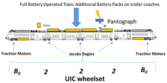
Figure 1.
Investigated BEMU derived from the original Hitachi Masaccio Platform.
Encumbrances available for battery installation are calculated by removing unused components from a Hitachi Masaccio HDMU [30].
Weights and encumbrances of the added storage system, including power converters, were calculated considering the performances of recent battery packs homologated for railway service [31].
Data of the chosen storage system are shown in Table 2: these data are coherent with performances of the BEMU [32] that achieved the last record of autonomy in Berlin (224 km).
Table 2.
Sizing of the installed storage system considering different constraints related to axle loads, available encumbrances, and exchanged power flows.
The size of the installed storage system is evaluated by exploiting the available loading capacity and encumbrances. As shown in Table 2, the chosen battery storage system has a size of about 1 MWh and an approximate weight of 9 tons.
The chosen battery pack fits the available encumbrances (minimal residual volume in a coach is reduced to 50 dm3). The weight, calculated as equivalent axle loads, respects the prescribed specification of 20 tons/axles.
The chosen batteries allow for a maximum charge/discharge rate of 3 C: a complete recharge of the battery can be performed in twenty minutes.
On partially electrified lines, a high charge rate allows for a fast recharge under electrified sections. Battery recharge cannot exceed limitations regarding the maximum power that can be collected from a 3 kV DC line using a standard pantograph.
These limitations, also described in Table 2, are prescribed by interoperability specifications [33].
The power flows associated with traction, regenerative braking and auxiliaries are also shown in Table 2.
3. Modelling of the Proposed BEMU
The adopted model is an extension of a tool that has been introduced to simulate hybrid fuel cell rolling stock [29,30].
Longitudinal equilibrium (1) of the convoy is solved considering applied longitudinal forces T and motion resistances such as Fp (grav. forces due to slope), Fa (distributed friction and aer. resistances), Fc (lumped motion res.), and Fi (inertial force):
The application of traction and braking forces is evaluated considering tabulated saturations of the involved components and plants.
Mixed electric and pneumatic braking is modeled considering adopted blending strategies. Involved power flows are calculated considering a fixed conversion efficiency of 92% for power converters. The efficiency of mechanical transmission is also constant and equal to 94%.
The general layout of a hybrid or electric powertrain is shown in Figure 2. Every source and the storage system are connected to a common DC Bus.
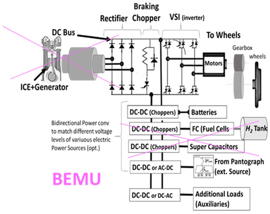
Figure 2.
Generalized powertrain layout for the proposed BEMU.
The connection with the DC bus can be direct, or it can be performed through an intermediate coupling stage (a power converter).
In this way, different solutions ranging from diesel-electric transmissions to hybrid fuel cell or battery-electric solutions can be modeled.
In this study, the DC bus is connected to the pantograph and, consequently, to the overhead line through a DC–DC converter. This converter is an H-bridge that can be used as a reversible chopper under DC lines.
Battery storage, DC Bus, and traction equipment are designed to operate at the same voltage level.
The proposed solution privileges autonomy in battery mode with respect to efficiency when operating under the electrified catenary.
3.1. Generalized Power Management
The adopted power management system is designed for easy customization and tuning. The original approach proposed in this work is a further evolution of a solution [34,35] that was developed for multimodal buses and trucks tested by the University of Florence at the ENEA laboratories of Roma Casaccia (Roma, Italy).
The layout of the proposed solution is shown in Figure 3: the scheme is derived from the one described in Figure 2 after the application of the described simplifications.
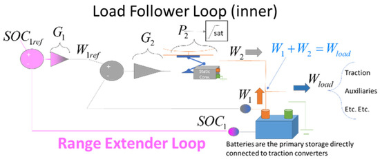
Figure 3.
Layout of the proposed power management system.
The vehicle loads are supposed to be fed by a primary storage system, the battery.
When the train is traveling under an unelectrified section, the primary storage is the only source of power for the train. Power W1 exerted by the battery is equal to the sum of train loads, Wload (2):
When the BEMU is traveling along an electrified line, power collected by the pantograph, W2, is controlled by a multi-quadrant chopper. As shown in Figure 3, the chopper is controlled by a closed loop called “Load Follower Loop”:
- W1ref is a reference value; the aim of the loop is to regulate the power W1 to follow W1ref, rejecting train load Wload as a disturbance. As an example, if W1ref is equal to zero, W2 will be equal to Wload.
- W1 is regulated by adjusting the power collected from the catenary W2 to minimize the error between W1ref and W1. The controller transfer function is called G2. The transfer function P2 has been introduced to model the dynamic response limits of the plant (as an example of the DC–DC converter), but in this work, it is supposed to be a unitary gain.
- In this paper, G2 is a linear PI controller (proportional–integral controller with gains Kp and Ki). The controller output is limited by a variable saturation block to protect the overhead line against excessive currents.
Assuming that the currents are not saturated (required current values are admissible with respect to the limits of connected infrastructure), W1 and W2 can be easily calculated in terms of transfer functions (3) and (4):
By performing a loop-shaping of the G2 controller (calibrating Kp and Ki), it is possible to modify the poles of both transfer functions W1(s) and W2(s).
In the hypothesis of constant W1ref, it is possible to evaluate the frequency response of W2(s) as a function of Kp and Ki: relatively low values of both gains (Kp = 10 Ki = 1) can assure stable behavior of the system and ensure it is performing. Figure 4a shows an example of the simulation where a sudden transition from the maximum traction level to the maximum service braking is simulated. The difference between the power required by the traction system and the response of the loop in terms of the power collected by the pantograph is negligible. Higher gains are possible. In this work, a low gain calibration was preferred to ensure a robust solution.
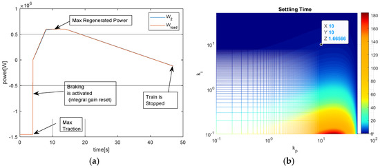
Figure 4.
Calibration of the G2 controller. (a) Response of the calibrated system during a sudden transition from maximum traction to max service braking. (b) Calculated settling time with respect to the proportional and integral gains of the controller.
As shown in Figure 4a, the integrated state of the PI controller is reset every time there is a sudden transition from traction to braking. This reset of the integral gain is performed to avoid delays that are potentially unsafe for braking.
The simulated scenario of Figure 4a is a worst-case condition since the typical behavior of the traction and braking loads is typically much smoother.
The corresponding behavior W2(s) in terms of settling time (time needs to reach 98% of a step excitation) with respect to the imposed values of Kp and Ki is shown. The chosen gains correspond to a settling time of about 1.7 s, as shown in Figure 4b. This response is fast enough since the dynamic behavior of the traction and braking loads is quite slow.
The internal load follower loop (controller G2) is not able to stabilize the state of charge of the battery SOC1. An external loop called the “Range Extender” stabilizes the battery’s state of charge, regulating the desired power flow W1ref.
This loop is called the Range Extender since the implemented functionality is quite similar to the range extender approach used for hybrid road vehicles [36]. The vehicle battery is periodically recharged accordingly to maintain the SOC within an assigned range.
In this study, a nonlinear controller G1 was preferred, as described by (5). The battery is recharged to keep SOC1 within a minimum (SOC1min) and a maximum level (SOC1max). The power flows are limited between two extreme values (W1max, W1min). In this work, the value of the exponent n is equal to 2.
In Table 3, the calibrated values of both controllers are briefly summarized.
Table 3.
Calibration of power management system.
Controller G1, as described by (5), has been calibrated to fully exploit the features of the proposed battery. The allowable state of charge SOC1 was reduced to a range between a minimum value of SOC1min equal to 0.2 and a maximum value, SOC1max, of 0.85. The value of SOC1min was chosen to assure a reasonable margin of robustness against battery aging.
The value of SOC1max was decreased to 0.85 to assure a reasonable safety margin against the risk of overvoltage to which the battery can be subjected during regenerative braking.
A maximum depth of discharge of about 65% helps to extend the life and reliability of the storage system, mitigating accelerated aging due to high recharge rates.
This choice is confirmed by the technical literature for LTO [35], NMC [36].or LiFePO4 [37] cells that are conventionally indicated as well-suited for railway applications.
3.2. Planning of Mission Profiles and High-Level Control of Longitudinal Dynamics
The proposed model calculates the energy consumption of the simulated train.
These results are affected by the adopted driving style. So, the simulated maneuvers must be smooth and realistic.
The mission profile is constrained to respect the same timetable that is currently performed by conventional trains on the same line.
As shown in the scheme of Figure 5, an inverse dynamic problem is solved to iteratively adjust the trajectory of the train according to the “Reduced Maximum Speed” strategy:
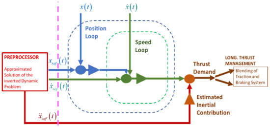
Figure 5.
Adopted approach for the offline generation of planned trajectory and for the high level of driving control of the simulated train.
- A constant acceleration is applied, and the imposed jerk is limited until the maximum speed is reached. The power and torque limitations of braking and traction equipment are considered.
- The maximum speed is optimized by the pre-processor to respect the mission timetable and the known speed limits of the line.
- The top speed is maintained until a braking phase is necessary.
- The maximum service braking begins as late as possible, with respect to the assigned stopping station.
The calculated position xref(t), speed and acceleration profiles are used as reference inputs for a closed-loop control described in Figure 5. The loop is composed of the nested position and speed loops aiming to regulate reference traction torques and braking of the train.
4. Partial Electrification of Firenze–Faenza Line
4.1. Description of Firenze–Faenza Line
The simulated line connects Firenze to Faenza (length of about 100 km), and it is currently unelectrified. As shown in Figure 6, the mean slope of the line is high (about 6 [m/km]).
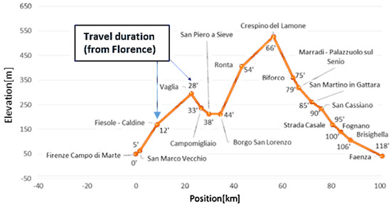
Figure 6.
Firenze–Faenza line, line profile, elevation and arrival time in each station starting from Florence.
The maximum slope of the line is about 15–20 [m/km] for several kilometers.
Thus, this mission profile is quite stressful for the current technology of BEMU.
With limited interventions on both vehicle and infrastructure technology, the performed service can be improved both in terms of autonomy and reliability.
The arrival times in each station taken from a real timetable are shown in Figure 6.
4.2. Partial Electrification of the Line: Optimization Process
The partial electrification of the line is optimized by adopting this methodology:
- Evaluation of Consumed Energy: A complete simulation of a mission profile is performed. To complete the assigned mission profile, the chosen capacity of installed batteries (117 [Wh/kg]) is not sufficient. So, the specific capacity of the battery is iteratively increased to find a value of stored energy that assures the completion of the mission (corresponding to a SOC reduction from 85% to 20%).
- Optimization of Electrified Sections: The energy needed to perform the mission is known, so it is possible to evaluate the minimum number of intermediate electrified sections that should ensure the completion of the mission using the nominal capacity of the train storage. The positioning and extension of the electrified recharge sections are optimized according to some criteria suggested by recent studies [38]. These criteria have been reworked in a form that facilitates system optimization. The main criterion that led to the numerical optimization was the minimization of the maximum DOD (Degree of Discharge) of the battery during the mission profile.
4.2.1. Evaluation of Consumed Energy
The rates of energy consumption are evaluated according to the mission profile shown in Figure 7, where a round trip from Florence to Faenza and return is considered.
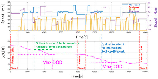
Figure 7.
Simulated mission profile considering the usage of an Intilion high energy storage (about 180 Wh/kg).
The consumption of auxiliaries when the train is stopped at stations is also considered. For the terminus stations of Florence and Faenza, the duration of the stop is increased to 15′ to ensure the preparation of the train. During the whole mission, batteries are recharged only by regenerative braking. To complete the mission, a battery with a minimum specific energy of 180 Wh/kg is needed (minimum state of charge of batteries equal to 20%).
This value is higher with respect to the nominal energy density of the battery (117 Wh/kg), so the amount of energy needed to complete the mission is 150% higher with respect to the nominal installed capacity. This value can currently be reached by installing high-energy lithium cells [31] that are also assessed for railway application. However, high-energy modules are currently limited in terms of charging rate (1 C-complete recharge in one hour). High-energy cells are more sensitive to aging when they are subjected to high power loads. Looking at the results of Figure 7, the following conclusions can be reached:
- The proposed model is able to generate a smooth mission profile that respects the assigned timetable and imposed kinematic constraints.
- Energy consumption is strongly influenced by line slope; in the uphill sections, consumption is much higher. In downhill sections, regenerative braking contributes to sustaining and even recharging onboard storage. Motion sensing influences the shape of the consumed energy, which is represented in Figure 7 in terms of DOD (degree of discharge of the battery).
- The consumed energy is 150% higher than the nominal capacity of the batteries. At least one intermediate recharge section is needed. The maximum recharge rate of batteries is 3 C, so the extension of electrified recharging sections should be 25–35% of the total length of the line. For the two runs from Florence to Faenza and vice versa, the position on which the maximum DOD occurs can be easily calculated. The optimal positioning of the intermediate recharge section corresponds to the position of the line that can be reached by consuming only half of the energy (half of the maximum DOD). The profile of the consumed energy is affected by motion sensing. Thus, the optimal positioning of the intermediate recharge station is different according to the motion sensing of the train.
4.2.2. Optimization of Electrified Sections for Dynamic Recharge
Criteria for the optimal positioning of recharging sections have been widely studied in the literature [39].
In this work, the following criteria are considered:
- Positioning of intermediate recharging stations must minimize the maximum DOD of batteries to maximize train autonomy and reduce battery aging.
- Construction and maintenance costs must be minimized. Electrification must take into account orography and the local availability of power sources.
- Electrification should be performed where high-power flows are statistically recorded. For example, around railway stations, high accelerations and decelerations are statistically more common. The slope of the line is another factor that contributes to increased energy consumption.
- The duration of a dynamic recharge under the catenary is limited by the length of the electrified section. So, the duration of the recharge can be inversely proportional to the mean train speed. It is convenient to electrify sections of the line in which the mean speed is not very high. In standstill conditions, the amount of power that can be collected is about one-tenth.
According to the above-described criteria, the choice of terminus stations of Firenze and Faenza (criteria 1 and 3 are automatically satisfied) is almost mandatory since both stations are connected to pre-existing electrified lines (criterion 2 is satisfied). At the terminus stations, the train will begin/end its service, so in these plants, long periods of time for recharge are available (criterion 4 satisfied).
The total length of a trip is about 100 km, so a total length of electrified sections between 25 and 35 km should be enough. A medium value of about 30 km is considered.
Optimization will be focused on the choice of intermediate recharging sections whose lengths are evaluated to be at least 10–15 km.
This minimum length of the electrified section justifies the cost of additional power stations. If the extension of the electrified section is too long, additional costs for power stations should be evaluated.
The remaining length of recharging sections is obtained by extending the length of the electrified sections around the terminus stations.
A numerical optimization is performed to evaluate the optimal positioning of the intermediate section according to criterion 1, the minimization of battery DOD.
As shown in Figure 8, simulations of roundtrip missions (Florence–Faenza–Florence) are repeated iteratively, shifting the positioning of the intermediate electrified section between the two locations:
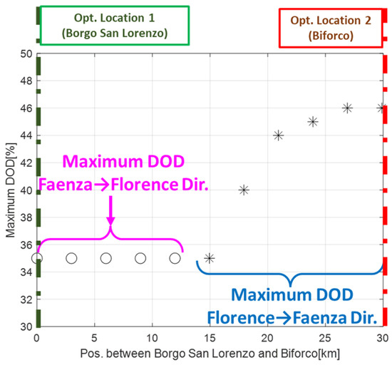
Figure 8.
Maximum DOD of the battery, as a function of the position of the intermediate electrified section.
- The first, Borgo San Lorenzo, corresponds to the location that minimizes the maximum DOD of the battery when the train is traveling in the direction from Florence to Faenza.
- The second, Biforco, is the location that minimizes battery DOD in the return run from Faenza to Florence.
As shown in Figure 8, there is no configuration that minimizes the maximum DOD recorded during a roundtrip mission under 35%. This value is reached when the intermediate recharge section is in Borgo San Lorenzo. In this case, a DOD of 35% is recorded when the train is returning from Faenza to Florence.
As the position of the intermediate recharge station is shifted to Biforco, the maximum recorded DOD increases to 45–46%. This value is recorded when the train is returning from Faenza to Florence. So, it can be concluded that Borgo San Lorenzo is an optimal location for the intermediate recharge location according to criterion 1.
As shown in Figure 9, the chosen location (around Borgo San Lorenzo) is also the most favorable in terms of construction and maintenance costs (criterion 2): the electrified section is located in a flat, accessible area in the Mugello valley between Campomigliaio and Panicaglia, where also connection to the power grid is relatively easy; in the same valley, the local line is adjacent to power stations of the high-speed railway line Firenze-Bologna and to the high-voltage electroduct from Florence to Bologna.
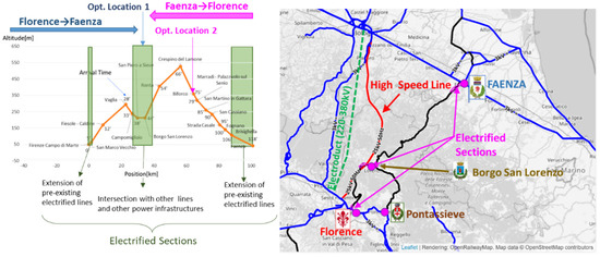
Figure 9.
Distribution of electrified sections along the Firenze–Faenza line.
Near Borgo San Lorenzo, as shown in Figure 9, there is an intersection with another unelectrified line also coming from Florence through Pontassieve.
An electrification in this area should also be synergic for this second railway line.
For concern criteria 3 & 4, along this section of the line, at least three intermediate stations are within a few kilometers, involving frequent stops and accelerations.
The performed choice penalizes onboard batteries during return trips from Faenza, so the electrified section from Faenza was slightly extended to compensate for this drawback partially. The distribution of the electrified sections along the line is shown in Table 4.
Table 4.
Position and length of electrified sections along the line.
5. Simulation Results
A simulation of a roundtrip mission along the Firenze–Faenza line has been performed to verify performances achieved with the partial electrification of the line.
Some results are shown in Figure 10: the train with nominal batteries can complete the roundtrip mission with a maximum DOD (Degree of Discharge of the Battery) of about 35% (0.35).
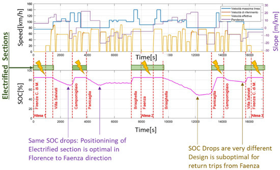
Figure 10.
Simulated mission (high-power batteries on partially electrified line from Florence to Faenza and return).
At each terminus station (Firenze or Faenza) and at the end of the intermediate recharge section, the battery is fully recharged. The system is energetically stable with respect to the proposed mission profile.
When traveling from Florence to Faenza, the maximum DOD is about 18%.
This value of DOD is equal for the two unelectrified sections, so for this motion sensing, the proposed layout of the line is optimal with respect to the features of the chosen train.
For the return trip (from Faenza to Florence), the maximum DOD is almost doubled (about 35%). The proposed solution, in this case, is suboptimal; however, the residual autonomy granted by the storage system is large enough to ensure a reliable service and the robust behavior of the system.
Evaluation of Collected Currents on Added Electrified Sections
The collected currents on the electrified sections are also calculated using the above-described model.
The aim of this calculation is the evaluation of losses along the line.
As shown in Table 5 and Figure 11, the calculation is performed considering the different distributions of the power stations (bilateral or single-sided) and different line impedances.
Table 5.
The parameters of the simulated lines and power stations for both the bilateral and single-sided power stations.
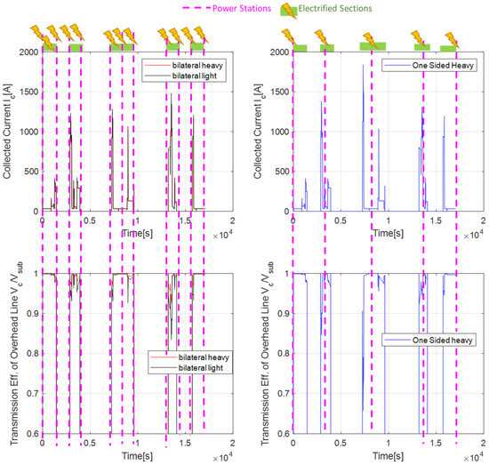
Figure 11.
Simulated behavior of collected current and power transmission efficiency.
The data for what concern simulated lines are taken from previous research activities [39].
The collected currents are compatible with the usage of the standard railway DC pantographs since their peak values are under 2000 [A], which is considered the maximum limit.
The lightest catenary of Table 5 can be adopted but only with bilateral power stations.
A one-sided power station is cheaper, but this solution can be adopted only with heavier catenaries.
By modifying the energy power management of the train, it is possible to add some further limitations on the collected currents, which should allow for lighter infrastructures.
However, the proposed solution seems to be quite robust with respect to the wide variations of impedance of the electrified sections.
6. Conclusions
In this work, the author introduced an example of a complete model that can be used to perform the preliminary sizing, calibration and evaluation of a BEMU considering different mission profiles. The same models can be used to synergically optimize the design of the line with respect to training performances and the adopted mission profile.
In this work, these activities have been performed considering the partial electrification of a mountain line (Firenze–Faenza). The performed design takes count of regenerative braking and consumption of auxiliaries. Optimization is difficult to reach as multiple features must be optimized.
The obtained results demonstrate the flexibility and usability of the proposed approach.
The design procedure of the recharge sections is optimal with respect to the chosen BEMU and mission profile. The modular logic proposed for the energy management of the train is effective and relatively simple to calibrate.
A synergic use of a BEMU train with partially electrified sections can be a feasible alternative to conventional diesel-propelled solutions.
The relative length of partially electrified sections with respect to total line length is currently constrained to be around one-third to one-fourth (25–33% of the total length of the line). The maximum recharge rate of the batteries and the maximum collected power of the pantograph are responsible for these limitations.
The passenger trains investigated in this work are short (about four coaches); further and future research activities will be dedicated to the investigation of longer compositions, such as battery-operated freight trains.
Funding
This study was carried out within the MOST—Sustainable Mobility National Research Center and received funding from the European Union’s NextGenerationEU (PIANO NAZIONALE DI RIPRESA E RESILIENZA (PNRR)—MISSIONE 4 COMPONENTE 2, INVESTIMENTO 1.4—D.D. 1033 17/06/2022, CN00000023). This manuscript reflects only the author’s views and opinions; neither the European Union nor the European Commission can be considered responsible for them.
Data Availability Statement
Data are contained within the article.
Conflicts of Interest
The author declares no conflict of interest.
List of Adopted Symbols and Acronyms
| Longitudinal efforts (traction and braking) applied to the whole railway composition. | |
| Motion resistances due to the altimetric profile of the line (gravitational forces) | |
| Distributed motion resistances due to internal friction and aerodynamic forces | |
| Lumped motion resistance due to line geometry such as curves (as example) | |
| Inertial forces calculated considering the total equivalent inertia of the train. | |
| Power exerted by the first on board storage system. | |
| Total power required by traction loads and auxiliary ones. | |
| Power exerted by the i-th onboard storage or power source. | |
| Transfer functions of the i-th control loop and transfer function of the i-th plant | |
| Desired/reference power profile for the first storage | |
| Proportional and integral gains of the controller (Supposed to be a proportional–integral controller) | |
| , | Maximum and minimum values of power exchanged by the first storage. |
| State of Charge of the first storage and corresponding allowable maximum and minimum values | |
| DOD | Degree of discharge of a battery (DOD = 100-SOC) |
| Exponent of the control law described in Equation (5) | |
| , | Specific energy and power of adopted batteries |
| Nominal power size of the battery | |
| Vsub | Output voltage of the power station |
| Vc | Voltage collected from the overhead line through a pantograph |
| Ic | Collected current from the overhead line |
| ηc | Efficiency of power transmission along the overhead line |
| ICE | Internal combustion engine |
| BEMU | Battery electric multiple unit |
| HDMU | Hybrid diesel multiple unit |
| FCHMU | Fuel cell hybrid multiple unit |
| LTO | Lithium titanate cells |
References
- European Alternative Fuels Observatory. Available online: https://alternative-fuels-observatory.ec.europa.eu/transport-mode/rail#:~:text=Regarding%20main%20lines%2C%2060%25%20of,is%20running%20on%20these%20lines (accessed on 1 June 2023).
- Distribution of Electrified Lines in Germany According Stadler. Available online: https://www.stadlerrail.com/static/img/flirt-akku/Stadler_BRD_Schienennetz_220613_en.jpg (accessed on 25 May 2023).
- Magelli, M.; Boccardo, G.; Bosso, N.; Zampieri, N.; Farina, P.; Tosetto, A.; Mocera, F.; Somà, A. Feasibility study of a diesel-powered hybrid DMU. Railw. Eng. Sci. 2021, 29, 271–284. [Google Scholar] [CrossRef]
- Singh, K.V.; Bansal, H.O.; Singh, D. A comprehensive review on hybrid electric vehicles: Architectures and components. J. Mod. Transp. 2019, 27, 77–107. [Google Scholar] [CrossRef]
- Zenith, F. Battery-powered freight trains. Nat. Energy 2021, 6, 1003–1004. [Google Scholar] [CrossRef]
- Laperrière, Y.; Eng, P. Realize your vision with Bombardier TALENT 3 BEMU. In Proceedings of the APTA 2019 Rail Conference, Toronto, ON, Canada, 24 June 2019; pp. 23–26. [Google Scholar]
- Böhm, M.; Del Rey, A.F.; Pagenkopf, J.; Varela, M.; Herwartz-Polster, S.; Calderón, B.N. Review and comparison of worldwide hydrogen activities in the rail sector with special focus on on-board storage and refueling technologies. Int. J. Hydrogen Energy 2022, 47, 38003–38017. [Google Scholar] [CrossRef]
- Stobnicki, P.; Gallas, D. Adoption of modern hydrogen technologies in rail transport. J. Ecol. Eng. 2022, 23, 84–91. [Google Scholar] [CrossRef]
- Zenith, F.; Isaac, R.; Hoffrichter, A.; Thomassen, M.S.; Møller-Holst, S. Techno-economic analysis of freight railway electrification by overhead line, hydrogen and batteries: Case studies in Norway and USA. Proc. Inst. Mech. Eng. Part F J. Rail Rapid Transit 2019, 234, 791–802. [Google Scholar] [CrossRef]
- Cole, C.; Sun, Y.; Wu, Q.; Spiryagin, M. Exploring hydrogen fuel cell and battery freight locomotive options using train dynamics simulation. Proc. Inst. Mech. Eng. Part F J. Rail Rapid Transit 2023. [CrossRef]
- Zhang, X.; Yang, D.; Luo, M.; Dong, Z. Load profile based empirical model for the lifetime prediction of an automotive PEM fuel cell. Int. J. Hydrogen Energy 2017, 42, 11868–11878. [Google Scholar] [CrossRef]
- Fragiacomo, P.; Piraino, F. Fuel cell hybrid powertrains for use in Southern Italian railways. Int. J. Hydrogen Energy 2019, 44, 27930–27946. [Google Scholar] [CrossRef]
- On Line Report on the First Service Operated by Coradia I-Lint. Available online: https://www.alstom.com/it/press-releases-news/2022/8/anteprima-mondiale-14-coradia-ilint-inizieranno-il-servizio-passeggeri (accessed on 1 July 2022).
- Bosch. Catalogues and Tech. doc. Related to High Pressure Tank from Hexagon™ Official Site. 2023. Available online: https://s3.eu-central-1.amazonaws.com/hexagonpurus/website/HexagonPurus_Brosch%C3%BCre_HighPressureType4.pdf (accessed on 13 July 2023).
- Luxfer. Catalogues and Tech. doc. Related to High Pressure Tank from Luxfer™ Official Site. 2023. Available online: https://www.luxfercylinders.com/ (accessed on 17 July 2023).
- Yilmaz, F.; Ozturk, M.; Selbas, R. Design and thermodynamic modeling of a renewable energy based plant for hydrogen production and compression. Int. J. Hydrogen Energy 2020, 45, 26126–26137. [Google Scholar] [CrossRef]
- Liu, X.; Li, K. Energy storage devices in electrified railway systems: A review. Transp. Saf. Environ. 2020, 2, 183–201. [Google Scholar] [CrossRef]
- Meehan, P.; Knibbe, R. Decarbonising Australian Railway Fleetswith Batteries; School of Mechanical and Mining Engineering, University of Queensland: Brisbane, Australia, 2022. [Google Scholar]
- Frith, J.T.; Lacey, M.J.; Ulissi, U. A non-academic perspective on the future of lithium-based batteries. Nat. Commun. 2023, 14, 420. [Google Scholar] [CrossRef] [PubMed]
- Hoffrichter, A.; Silmon, J.; Schmid, F.; Hillmansen, S.; Roberts, C. Feasibility of discontinuous electrification on the Great Western Main Line determined by train simulation. Proc. Inst. Mech. Eng. Part F J. Rail Rapid Transit 2012, 227, 296–306. [Google Scholar] [CrossRef]
- Abdurahman, B.M.; Harrison, T.; Ward, C.P.; Midgley, W.J.B. An investigation into intermittent electrification strategies and an analysis of resulting CO2 emissions using a high-fidelity train model. Railw. Eng. Sci. 2021, 29, 314–326. [Google Scholar] [CrossRef]
- Jakubowski, A.; Karkosińska-Brzozowska, N.; Karwowski, K.; Wilk, A. Storage electric multiple units on partially electrified suburban railway lines. Przegląd Elektrotechniczny 2020, 1, 158–161. [Google Scholar] [CrossRef]
- Schenker, M.; Kuhlkamp, F. Optimization Model for Operation of Battery Multiple Units on Partly Electrified Railway Lines. In Proceedings of the 2021 Sixteenth International Conference on Ecological Vehicles and Renewable Energies (EVER), Monte-Carlo, Monaco, 5–7 May 2021; pp. 1–8. [Google Scholar] [CrossRef]
- Juston, M.; Vulturescu, B.; Chamaret, A. A statistical approach for the optimal sizing of partial electrification for battery trains. In Proceedings of the 2023 IEEE International Conference on Electrical Systems for Aircraft, Railway, Ship Propulsion and Road Vehicles & International Transportation Electrification Conference (ESARS-ITEC), Venice, Italy, 29–31 March 2023; pp. 1–6. [Google Scholar] [CrossRef]
- IRS 60608-1ed; Conditions to Be Complied with for the Pantographs of Tractive Units Used in International Services. 2019. Available online: https://www.mystandards.biz/standard/irs-60608-1ed--1.7.2019.html (accessed on 14 February 2023).
- Tech Documents Related to Results of the European Research Project FCH2RAIL. Available online: https://verkehrsforschung.dlr.de/public/documents/2022/FCH2RAIL_ProjectOverview_2022.pdf (accessed on 14 February 2023).
- Alessandro Vannucchi, La piattaforma MASACCIO di Hitachi Rail per la Decarbonizzazione dei Treni Regionali, La Transizione Tecnologica Dalla Trazione Diesel ai Nuovi Treni a Batteria e Idrogeno, Presentation Performed on 29th Sept. 2021 at Convegno Webinar at Expo Ferroviaria, available for download at the official site of ANIE. Available online: https://anie.it/ (accessed on 1 March 2023).
- Tech Data from Staedler. Available online: https://www.stadlerrail.com/en/flirt-akku/details/ (accessed on 14 May 2023).
- Pugi, L.; Berzi, L.; Cirillo, F.; Vecchi, A.; Pagliazzi, V. A tool for rapid simulation and sizing of hybrid traction systems with fuel cells. Proc. Inst. Mech. Eng. Part F J. Rail Rapid Transit 2022, 237, 104–113. [Google Scholar] [CrossRef]
- Pugi, L.; Berzi, L.; Spedicato, M.; Cirillo, F. Hydrogen for railways: Design and simulation of an industrial benchmark study. Int. J. Model. Identif. Control. 2023, 43, 43–53. [Google Scholar] [CrossRef]
- Tech Data from Hoppecke. Available online: https://www.hoppecke.com/fileadmin/Redakteur/Hoppecke-Main/Products-Import/rail_hv-modul_data_sheet_de.pdf (accessed on 14 May 2023).
- Information of Stadler AKKU Autonomy Record. Available online: https://youtu.be/MGho18fCZKo (accessed on 3 June 2023).
- Energy TSI (Technical Specifications for Interoperability)|European Union Agency for Railways, Available online at European Railway Agency Site. Available online: https://www.era.europa.eu (accessed on 1 January 2023).
- Pugi, L.; Alessandrini, A.; Barbieri, R.; Berzi, L.; Pierini, M.; Cignini, F.; Genovese, A.; Ortenzi, F. Design and testing of a supercapacitor storage system for the flash recharge of electric buses. Int. J. Electr. Hybrid Veh. 2021, 13, 57–80. [Google Scholar] [CrossRef]
- Tran, M.-K.; Bhatti, A.; Vrolyk, R.; Wong, D.; Panchal, S.; Fowler, M.; Fraser, R. A Review of Range Extenders in Battery Electric Vehicles: Current Progress and Future Perspectives. World Electr. Veh. J. 2021, 12, 54. [Google Scholar] [CrossRef]
- Mathieu, R.; Briat, O.; Gyan, P.; Vinassa, J.-M. Comparison of the impact of fast charging on the cycle life of three lithium-ion cells under several parameters of charge protocol and temperatures. Appl. Energy 2021, 283, 116344. [Google Scholar] [CrossRef]
- Nemeth, T.; Schröer, P.; Kuipers, M.; Sauer, D.U. Lithium titanate oxide battery cells for high-power automotive applications—Electro-thermal properties, aging behavior and cost considerations. J. Energy Storage 2020, 31, 21–34. [Google Scholar] [CrossRef]
- Fedele, E.; Iannuzzi, D.; Del Pizzo, A. Onboard energy storage in rail transport: Review of real applications and techno-economic assessments. IET Electr. Syst. Transp. 2021, 11, 279–309. [Google Scholar] [CrossRef]
- Frilli, A.; Meli, E.; Nocciolini, D.; Pugi, L.; Rindi, A. Energetic optimization of regenerative braking for high speed railway systems. Energy Convers. Manag. 2016, 129, 200–215. [Google Scholar] [CrossRef]
Disclaimer/Publisher’s Note: The statements, opinions and data contained in all publications are solely those of the individual author(s) and contributor(s) and not of MDPI and/or the editor(s). MDPI and/or the editor(s) disclaim responsibility for any injury to people or property resulting from any ideas, methods, instructions or products referred to in the content. |
© 2023 by the author. Licensee MDPI, Basel, Switzerland. This article is an open access article distributed under the terms and conditions of the Creative Commons Attribution (CC BY) license (https://creativecommons.org/licenses/by/4.0/).