Article

Effect of Carboxyl-Doped Graphene Nanoplatelets as an Electrode for Supercapacitors According to Surface Property Changes via the Control of Conditions

1
Department of Chemical Engineering, College of Engineering, Wonkwang University, Iksan 54538, Republic of Korea
2
Nanoscale Sciences and Technology Institute, Wonkwang University, Iksan 54538, Republic of Korea
3
ICT Fusion Green Energy Research Institute, Wonkwang University, Iksan 54538, Republic of Korea
*
Authors to whom correspondence should be addressed.
Energies 2024, 17(1), 102; https://doi.org/10.3390/en17010102
Submission received: 1 December 2023 / Revised: 18 December 2023 / Accepted: 22 December 2023 / Published: 23 December 2023
(This article belongs to the Section D2: Electrochem: Batteries, Fuel Cells, Capacitors)

Abstract

:
Energy storage systems (ESSs) are attracting increasing attention for the development of sustainable and renewable energy technologies owing to limited fossil fuels. Supercapacitors are gaining significant interest as energy storage devices owing to their high-power density and long-term cycle stability. The use of suitable electrode materials affects the performance of supercapacitors. In this study, we fabricated a carboxyl-doped graphene nanoplatelet (CGnP) via a mechanochemical reaction. Additionally, CGnP was activated by controlling parameters such as temperature, flow rate, and maintenance period and evaluated as an electrode material for supercapacitors. The effect of the specific surface area (SSA) and functional groups of the fabricated samples on the capacitance was confirmed by controlling the activation parameters. The activated CGnP with 300 mL/min of CO2 at 1173 K for 4 h exhibited a high SSA of 1300 m2/g. The activated CGnP (180 F/g), with a high SSA, showed an increased capacitance of 46% compared to pristine CGnP (123 F/g). Additionally, activated CGnP1100 demonstrated good wettability and exhibited excellent stability with a low capacitance decrease of 6.1%, even after 10,000 cycles.

1. Introduction

The importance of developing sustainable and renewable energy technologies is increasing to address the challenges of climate change and fossil fuel depletion. The conversion and storage technologies for energy produced from sustainable and renewable energy sources are crucial because they contribute to energy efficiency. Energy storage systems (ESSs) are devices designed for efficient energy use. Lithium-ion batteries and supercapacitors are used as electrical energy storage systems [1,2,3,4]. Among these ESSs, supercapacitors, also known as ultracapacitors, are promising electrochemical energy storage devices with high power density and long-term cycle stability [5,6]. Owing to these characteristics, supercapacitors are used for various applications in fields such as industry, transportation, and portable electronic devices [7,8,9].
Supercapacitors are generally classified into electrical double-layer capacitors (EDLCs) and pseudocapacitors (PCs) based on their charge storage mechanism. PCs store charge through redox reactions at the interface between the electrode and electrolyte [10,11]. PCs usually use metal oxides such as RuO2 [12,13], MnO2 [14,15], NiCo2O4 [16,17], and NiO [18,19] as electrode materials owing to their higher capacitance than EDLCs. However, PCs have a high cost and high equivalent series resistance [20,21].
On the other hand, EDLCs store their charge through charge separation owing to an electric double layer at the interface of the electrode and electrolyte [22]. Moreover, they mainly use carbon materials such as activated carbon [23,24], graphene [25,26,27,28,29], graphene oxide [30,31,32], and carbon nanotubes [33,34] as electrodes (Table 1). EDLCs using carbon materials as electrodes have advantages such as environmental friendliness, low cost, easy availability, and stability [35,36]. The capacitance of EDLCs is influenced by the surface properties of electrode materials [37]. Elisadiki et al. reported that electrode materials with a high specific surface area (SSA) and good wettability contribute to capacitance [38]. Therefore, graphene, which has a high SSA and electric conductivity, is a promising candidate as an electrode material for EDLCs. However, during the fabrication process for electrode applications, graphene often re-stacks and agglomerates, resulting in a decrease in SSA. To address this problem, many researchers have used graphene with different shapes and properties, such as graphene nanoplatelets (GnPs), as electrode materials [39,40,41]. GnPs have a high SSA, uniform pore size, and environmentally friendly characteristics; however, their performance is shorter than that of graphene. Therefore, to use GnPs as the electrode materials, the performance must be improved by optimizing the SSA, appropriate pore size, and wettability. In general, the SSA of carbon materials can be increased via the activation and reaction of carbon materials. Physical activation using CO2 and H2O can increase the SSA of carbon materials more safely, efficiently, and conveniently than chemical activation using chemicals such as phosphoric acid. The activated material develops more pores and shapes through the activation reaction, resulting in a higher SSA, thus optimizing electric double-layer capacitance properties [42,43]. Also, Jeon et al. reported that GnPs can have various functional groups on the edges of GnPs through mechanochemical reactions [44]. Among these functional groups, a hydrophilic carboxyl group on carbon materials can contribute to the stability of the capacitor owing to its good wettability with the electrolyte [45,46].
This study increased the specific surface area of GnPs with functional groups through an activation process that controlled the parameters (temperature, gas flow rate, and maintenance period). In addition, the specific surface area, pore size distribution, and electrochemical performance were confirmed by controlling the activation parameters. As the carboxyl group located at the edge of CGnP was maintained during the activation process, it exhibited good wettability and excellent capacitance. Among them, CGnP1100, which has a high specific surface area, the appropriate development of the pore, and good wettability, showed excellent capacitance and stability, suggesting that it is suitable as an EDLC electrode material.

2. Experimental Section

2.1. Synthesis of Carboxylated Graphene Nanoplatelet (CGnP) and Activated CGnP

CGnP was obtained through the ball milling method [44]. In total, 320 g of the pristine graphite (32 mesh, Sobaek Industry, Inc., Yangsan, Republic of Korea) was placed in a container with 1 kg of 5 mm diameter stainless-steel balls and was completely removed from the air. Next, the stainless-steel container was filled with 4 MPa of CO2 and fixed on a planetary ball milling machine (pulverisette 5, Fritsch). The material was obtained via ball milling at 350 rpm for 48 h and treated with a 1 M HCl aqueous solution to remove metal impurities from the resulting material. Finally, the product was freeze-dried at 153 K for 48 h under a reduced pressure of 0.05 mmHg to obtain 365.6 g of black powder CGnP.
The CGnP activation was conducted by controlling the temperature, gas flow rate, and maintenance period parameters. The CGnP was activated under a high-purity CO2 atmosphere by placing 10 g of CGnP into the tube furnace. The control of the activation parameters was divided into three categories to obtain the activated CGnP (Table 2). Category 1 refers to temperature change, Category 2 refers to the gas flow rate change, and Category 3 refers to maintenance period change.

2.2. Characterization

The morphological observation of CGnP was investigated through field-emission scanning electron microscopy (FE-SEM; S-4800, Hitachi, Tokyo, Japan). The crystal structure of the sample was analyzed via X-ray diffraction (XRD; MiniFlex 600, Rigaku, Tokyo, Japan) using Cu-Kα radiation in the 2θ range. The SSA and pore volume of activated CGnP were determined by applying the Brunauer–Emmett–Teller equation (BET; BELSORP-miniII, MicrotracBEL, Osaka, Japan) from the N2 adsorption/desorption isotherm at 77 K. The chemical bonds of the samples were analyzed using a Fourier-transform-infrared spectroscopy (FT-IR; Spectrum Two, PerkinElmer, Waltham, MA, USA). The hydrophilic nature of CGnP was confirmed through contact angle measurement (Smart Drop, Femtobiomed, Republic of Korea).

2.3. Electrochemical Test

To evaluate the electrochemical performance of EDLCs, galvanostatic charge–discharge (GCD) and electrochemical impedance spectroscopy (EIS) were measured using a battery testing system (BCS-815, Bio-logic, Göttingen, Germany). The electrode slurry comprised 95 wt.% of active material (CGnP), 5 wt.% of the binder (polyvinylidene fluoride), and N-methly-2-pyrrolidone as the solvent. A 6 M KOH aqueous solution was used as the electrolyte, and the area of the electrode made from the electrode slurry was 1 cm2. The slurry was prepared by repeating the pressing and drying process on nickel foil used as a current collector. GCD was measured at a voltage of 0 to 0.9 V and 1 mA/cm2. EIS was measured in the frequency range of 10 kHz to 100 mHz. Through GCD, specific capacitance was calculated using the equation below.
C = ( I · t ) / ( m · V )
C (F/g) obtained from the equation represents the specific capacity. I (mA) is the discharge current, ∆t (s) is the discharge time, m (mg) is the mass of the electrode, and ∆V (V) is the discharge voltage.

3. Results and Discussion

Activated CGnP samples were synthesized by controlling the temperature, gas flow rate, and maintenance period parameters. The controlled activation parameter results were exhibited by the N2 adsorption/desorption isotherm and SSA, calculated using the BET equation at relative pressure P/P0 = 0.990 values. The SSA values are summarized in Table 3, and activated CGnP samples are denoted according to their SSA values: CGnP700, CGnP900, CGnP1100, and CGnP1300, in the order of activation conditions mentioned in the synthesis section earlier.
The SSA of CGnP had a value of 485.56 m2/g, and CGnP700 after CO2 activation had a value of 730.43 m2/g, indicating that SSA increased by developing porosity on the surface of the carbon material during the CO2 activation process [50]. Compared to CGnP700 (973 K), CGnP900 (1173 K), activated with CO2 at a higher temperature, showed a larger specific surface area of 927.69 m2/g. When the activation temperature increased from 973 K to 1173 K, the reaction rate between carbon and CO2 became faster. Therefore, the release rates of volatile matter were higher, resulting in a high specific surface area and an increase in the total pore volume, as shown in Table 3 [51]. In addition, CGnP1100 (300 mL/min) was activated at a higher CO2 flow rate than CGnP900 (100 mL/min), showing a value of 1183.7 m2/g owing to the supply of more activation agents [52]. CGnP1300 (4 h), activated with a longer reaction period than CGnP1100 (2 h), showed a value of 1396.7 m2/g. As shown in Figure 1a, the activated CGnPs exhibited a type IV isotherm with a well-developed hysteresis loop at P/P0 = 0.2–0.9, indicating the formation of mesopores (2–50 nm) [53]. In Figure 1a, the adsorption number of activated samples increased significantly in the low relative pressure region below P/P0 = 0.1, indicating that micropores of approximately 2 nm or less underwent the activation process. Through these results, it can be confirmed that not only mesopores, which facilitate the electrolyte ion diffusion into the carbon materials, but also micropores, which provide abundant adsorbing sites for the ions, develop simultaneously through the activation process. Pore size distribution was analyzed to confirm the changes in the development of micropores and mesopores according to activation conditions. The pore size distribution of all CGnP samples is shown at once in Figure S1. As in the MP plot (Figure 1b–d) and Barrett–Joyner–Halenda (BJH) plot (Figure 1e–g), Figure 1b,e exhibits the micropore and mesopore pore size distributions of CGnP via the activation temperature corresponding to Category 1, respectively. When activation was performed at a high temperature, micropores, mesopores, and macropores (>50 nm) were also well-developed owing to an increased reaction rate between carbon and carbon dioxide, which is an activating medium. In Category 2, which examined the effect of the amount of the activation medium, all types of pores grew better, as shown in Figure 1c,f. However, when the amount of activation medium increased, micropore formation further developed compared to when the activation temperature was increased. In Category 3, where only the activation period was changed at the same temperature and the same amount of activation medium was supplied, the growth of mesopores and macropores was not significantly observed. However, the growth of micropores is confirmed in Figure 1d,f, indicating that before sufficient activation, all types of pores grew simultaneously. However, after the macropores and mesopores grew sufficiently, the micropores grew on the surface of the grown pores. Through the analysis of the nitrogen adsorption and desorption experiment results, a specific surface area with well-developed pores of various sizes was obtained via controlling the activation experiment variables, and the results are summarized in Table 3. Furthermore, all prepared samples showed sufficient surface area and pore characteristics that could be used as electrodes for EDLC.
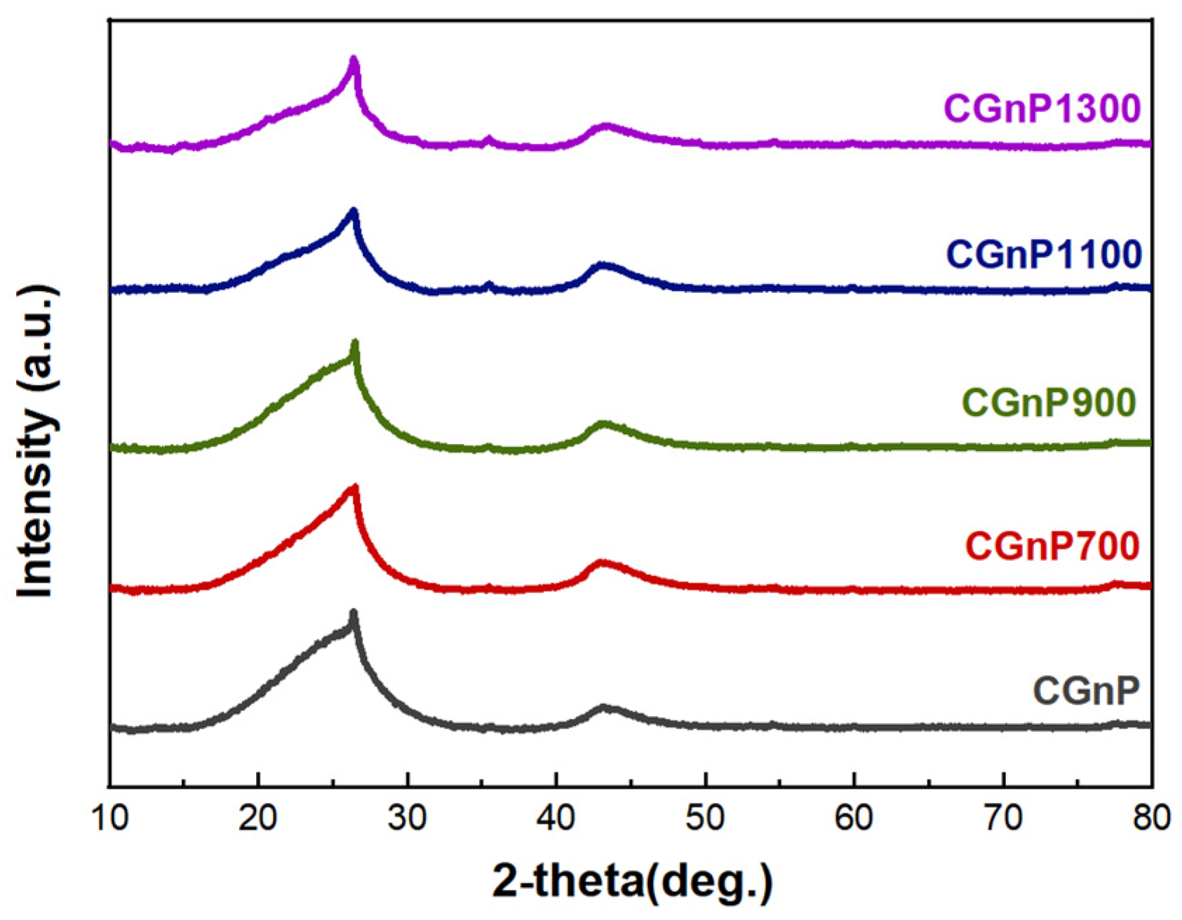
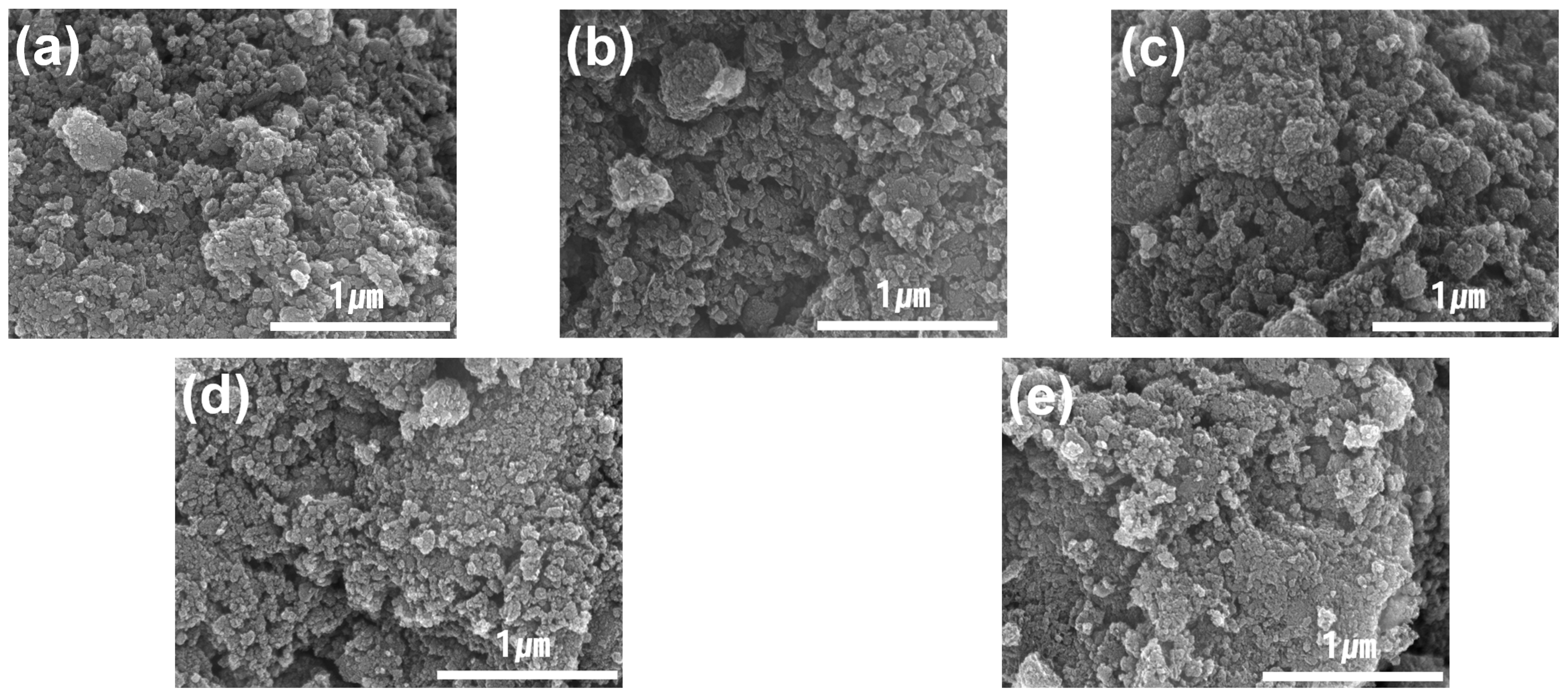
XRD and FT-SEM analysis were conducted to confirm the crystal structure and surface morphology of all samples based on the control of activation conditions. Figure 2 shows the XRD patterns of all samples. The XRD patterns of all the samples exhibit a typical peak in graphene corresponding to an interlayer d-spacing of 0.34 nm associated with hexagonal graphite at approximately 26°. However, no changes in other XRD patterns can be observed with the control of activation conditions. Additionally, it shows a broad XRD peak pattern at 15~30° compared to graphite, indicating the edge expansion of CGnP [54]. Figure 3 shows the surface morphology of the synthesized samples through FT-SEM images. In high-magnification images, all samples have very small particle sizes and rounded edges. The particle shape did not affect the control of activation conditions. Activation based on parameter control does not significantly impact the structure and surface shape of the crystal.
Electrochemical measurements were conducted to compare electrochemical performance according to the activation conditions. As shown in Figure 4a–c, the capacitance of the CGnP electrode was evaluated using GCD in the range of 0~0.9 V and a constant current density of 1 mA/cm2. The GCD curve is shown according to the activation condition temperature control (Figure 4a), flow rate control (Figure 4b), and maintenance period control (Figure 4c). In Figure 4, the specific capacitance of the CGnP electrode shows a value of 123 F/g. The activated samples CGnP700 (973 K) and CGnP900 (1173 K) with a controlled temperature show specific capacitance values of 140 and 152 F/g, respectively (Figure 4a). The capacitance of CGnP700 increased by 13% compared to CGnP. The capacitance of CGnP900 increased by 9% compared to CGnP700, owing to the increased SSA due to the control of the activation temperature. In addition, changes in the flow rate of CO2, the activation medium, also contributed to an increase in charging capacitance. As shown in Figure 4b, CGnP900 (100 mL/min) and CGnP1100 (300 mL/min), based on the CO2 flow rate, showed values of 152 and 176 F/g, respectively, increasing by 19%. The development of mesopores and micropores in CGnP1100, as the CO2 flow rate increased, contributed to the capacitance. On the other hand, CGnP1300, which had a capacitance of 180 F/g, showed an increased rate of 2% compared to CGnP1100 (Figure 4c). Therefore, CGnP1300 did not exhibit a significant improvement in capacitance under the activation period condition owing to the development of micropores compared to other samples. However, CGnP1300 showed a 46% improvement compared to pristine CGnP, owing to its high SSA and the presence of mesopores and micropores. Therefore, the activation condition’s effect on SSA and capacitance can be confirmed. However, the SSA and capacitance values were not proportional, which might have contributed to the low presence of mesopores [55]. Figure 4 exhibits the changes in IR drop related to the activation condition and SSA. CGnP, CGnP700, CGnP900, CGnP1100, and CGnP1300 have IR drop values of 213, 123, 100, 89, and 88 mV, respectively. These values of the IR drop are related to the resistance and conductivity of the electrode material [56]. Impedance analysis was performed to confirm the changes in the charging capacitance and electrical conductivity based on these activation conditions.
The EIS curves of CGnP electrodes are shown in Figure 5a–c. The EIS curve is shown according to the activation conditions of the temperature (Figure 5a), flow rate (Figure 5b), and maintenance time (Figure 5c). Additionally, Figure 5a–c shows the internal resistance (RS), representing the intrinsic electrical resistance of the electrode, and the charge transfer resistance (RCT), which exhibits the electrochemical reaction process when electrons move at the electrode interface [57,58]. CGnP, CGnP700, CGnP900, CGnP1100, and CGnP1300 have RS values of 4.40, 3.58, 3.54, 3.30, and 2.63 Ω and RCT values of 89.81, 47.72, 46.69, 40.76, and 44.89 Ω, respectively. The RS value is related to the IR drop and shows the electrode material’s low resistance and high conductivity upon activation. We suggest that the activation reaction occurs in the internal C=C bond rather than the edge of the C=O bond, resulting in improved conductivity owing to free electrons created from breaking the C=C bond. In addition, the value of RCT showed a small semicircle depending on activation. Owing to the development of micropores and mesopores, small semicircles appeared, owing to the smooth formation of an electric double layer and electrochemical reactions [59]. When comparing CGnP1100 and CGnP1300, the RCT value increased as the activation period increased, indicating that the electrochemical reaction rate of the electrode material changed or affected the formation of an electric double layer owing to changes in the activation maintenance period. In addition, a linear Warburg of CGnP1100 is closer to the ideal linear Warburg of 45°. CGnP, CGnP700, CGnP900, CGnP1100, and CGnP1300 showed a linear Warburg of 58, 50, 50, 47, and 51°, respectively. Compared to CGnP, the activation samples had a value closer to the ideal linear Warburg of 45°. A value similar to 45° improved the wettability between the electrode and the electrolyte through excellent ion diffusion, affecting the capacitance and stability [60,61,62].
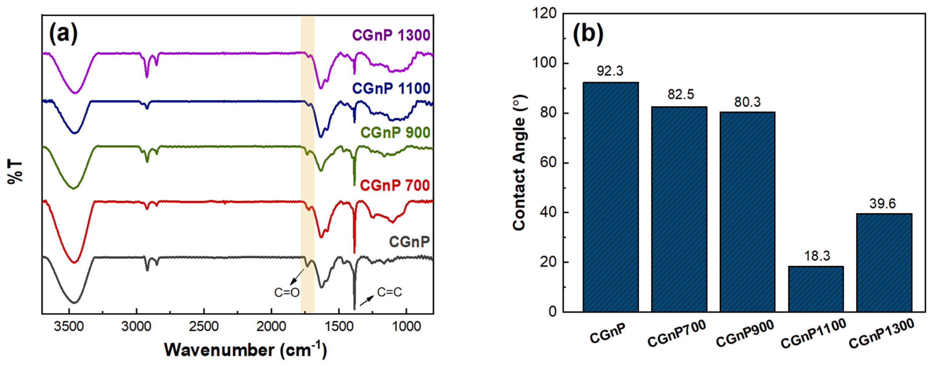
The chemical bond structure was confirmed through the FT-IR measurement to support electrochemical performance. In Figure 6a, all samples show a C=C bond peak at approximately 1383 cm−1 and a C=O bond peak at 1726 cm−1. The rations of C=O/C=C of CGnP, CGnP700, CGnP900, CGnP1100, and CGnP1300 are 0.11, 0.13, 0.17, 0.33, and 0.32, respectively. Therefore, as the activation temperature (from 973 K to 1173 K) and flow rate (from 100 mL/min to 300 mL/min) increase, there are more C=O bonds than C=C bonds. As the activation temperature and CO2 flow rate change, activation becomes more active owing to higher kinetic energy and increased activation media. At this time, an activation reaction occurs at the C=C bonds inside rather than the C=O at the edge of CGnP, breaking the C=C bonds and resulting in relatively more C=O than C=C. The presence of C=O can contribute to improving electrochemical performance and is consistent with the significant increase in capacitance owing to the flow rate control compared to the increase in capacitance owing to the temperature and maintenance period control [63]. Increasing other activation conditions relatively reduced the C=C double bond; however, increasing the activation maintenance period also caused a reduction in the C=O double bond. This means that as the activation maintenance period increases, after the sufficient activation process in the internal C=C bonds, the activation process also appears in the edge of C=O bonds. As shown in Figure 6b and Figure S2, the wettability of the carboxyl group of CGnP identified through FT-IR was identified by measuring the contact angle. The contact angles of CGnP, CGnP700, CGnP900, CGnP1100, and CGnP1300 were 92.3, 82.5, 80.3, 18.3, and 39.6°, respectively. As confirmed by FT-IR, it showed good wettability in proportion to the ratio of hydrophilic carboxyl groups. In addition, contact angle measurements indicated that electrodes with similar values to the ideal linear Warburg values in the EIS curve exhibited good wettability. Furthermore, this good wettability improved the permeability of the electrolyte into the electrode, affecting capacitor performance and increasing cycle stability [64,65].
Figure 7 shows the XPS spectrum of activated CGnP according to activation parameters. As shown in Figure 7a, CGnP samples confirmed the physically adsorbed oxygen peak at 532 eV and the carbon peak at 284.3 eV. In the C 1s spectrum in Figure 7b–f, the C-C, C-OH, and O=C-OH bonds are fitted at about 284.5, 286.1, and 288.6 eV, respectively. The C-C/(C-OH+O=C-OH) ratios of CGnP, CGnP700, CGnP900, CGnP1100, and CGnP1300 exhibit values of 2.66, 2.56, 2.35, 1.51, and 1.90, respectively. The increase in the proportion of carboxyl groups with the increasing activation parameters is consistent with what was seen through FT-IR and contact angles. As the activation parameter increases, the activation reaction occurs at the internal carbon bond rather than the edge C=O, and after a sufficient activation process, it was confirmed through the C 1 XPS spectrum and FT-IR that the activation process also occurred at the edge C=O bond.
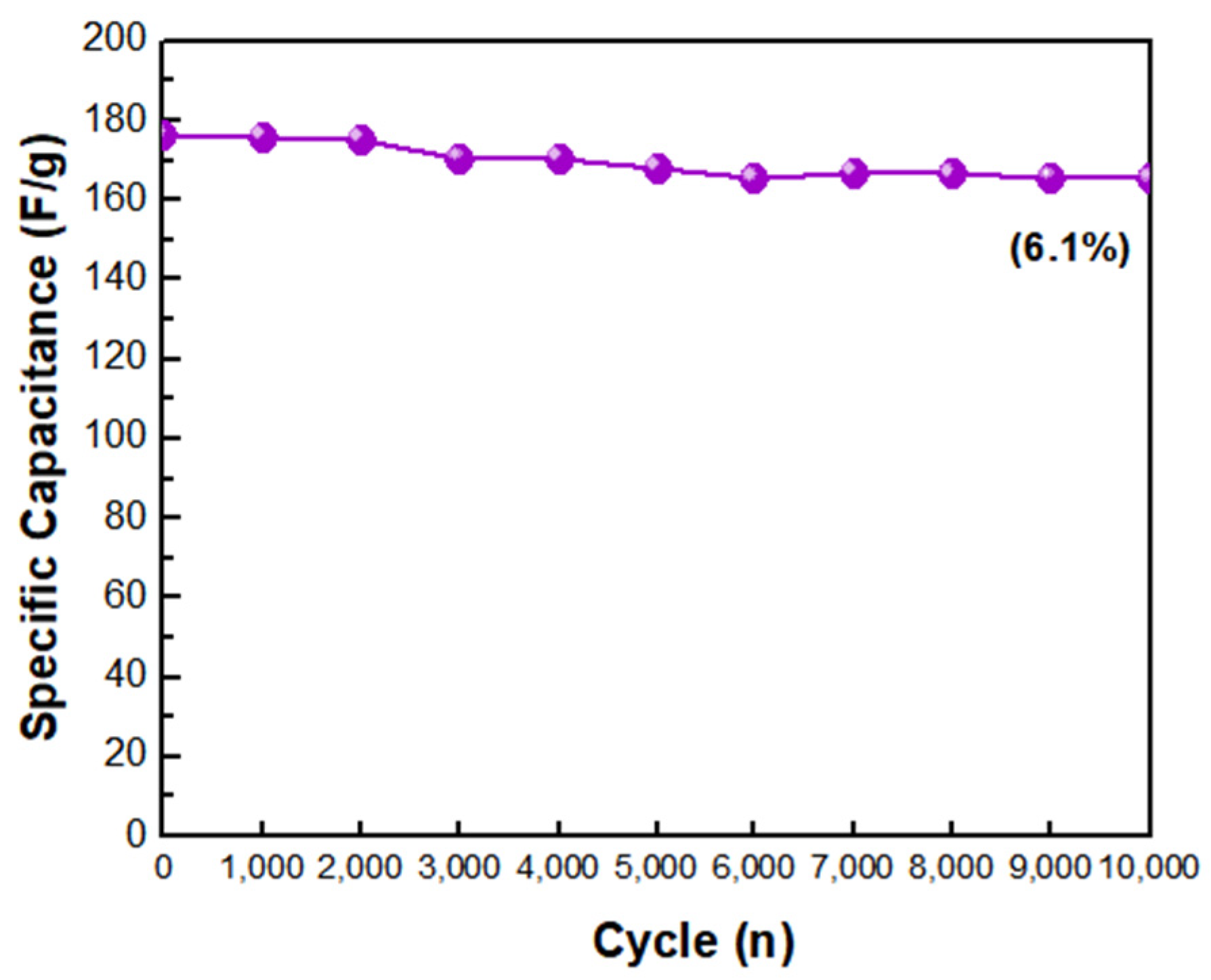
We investigated the performance of the capacitor according to the activation conditions and the cyclic stability of CGnP1100, which showed good wettability. The cycle stability test was conducted at a voltage of 0~0.9 V and a current density of 1 mA/cm2, as shown in the GCD curve, and the stability of the electrode was investigated after 10,000 cycles. As shown in Figure 8, CGnP1100 showed a 6.1% decrease in capacitance after 10,000 cycles, which could be attributed to the activation reaction occurring at the C=C bond rather than the C=O bond (carboxyl group) of the functional group during the activation process. CGnP1100 had relatively more C=O bonds than C=C bonds; therefore, good wettability improved electrolyte permeability to the electrode and showed excellent stability. CGnP1100, which has a high SSA and good wettability, exhibits excellent stability and is suitable as an electrode material for EDLCs.

4. Conclusions

In this study, CGnP was fabricated from graphite via a mechanochemical reaction. The fabricated CGnP was activated with CO2 under various conditions to confirm changes in the sample characteristics according to parameter control. Activated CGnP showed that the SSA value increased according to the control of the activation parameters. After all, sufficient pores were developed during the activation condition control (temperature, gas flow rate), and micropores were further developed with activation according to the maintenance period. The crystal structure and the sample’s surface morphology did not affect the control of activation parameters. Activated samples did not show a proportional increase in capacitance compared to the SSA values. Therefore, capacitance does not depend only on the SSA, and the development of appropriate pores also contributes to improving capacitor performance. The ratio of C=O/C=C increased with higher activation parameters (temperature, flow rate, and maintenance period). Compared to the internal C=C bonds, the C=O bonds remained unbroken at the edges during activation. SSA, appropriate pores, and good wettability owing to the presence of carboxyl groups supported capacitor performance. This good wettability affected the performance and cycling stability of the capacitor. CGnP1100, with a high SSA and good wettability, exhibits a high specific capacitance of 176 F/g owing to the development of appropriate pores (micropores and mesopores) and shows excellent stability with a low reduction rate of 6.1% even after 10,000 cycles. Owing to this SSA, appropriate pore development, and wettability, CGnP1100 is promising as an electrode material for EDLCs.

Supplementary Materials

The following supporting information can be downloaded at: https://www.mdpi.com/article/10.3390/en17010102/s1, Figure S1: (a,b) Pore size distribution of CGnP and activation of CGnP samples; Figure S2: Contact angle image of (a) CGnP, (b) CGnP700, (c) CGnP900, (d) CGnP1100, and (e) CGnP1300.

Author Contributions

Writing—original draft, J.-W.P.; Writing—review and editing, Y.-W.J. and I.-Y.J. All authors have read and agreed to the published version of the manuscript.

Funding

This research was supported by the “Regional Innovation Strategy (RIS)” through the National Research Foundation of Korea (NRF), funded by the Ministry of Education (MOE) (2023RIS-008).

Data Availability Statement

The original contributions presented in the study are included in the article. Further inquiries can be directed to the corresponding author.

Conflicts of Interest

The authors declare that they have no competing financial interest or personal relationships contributing to this article.

References

  1. Yan, J.; Wang, Q.; Wei, T.; Fan, Z. Recent Advances in Design and Fabrication of Electrochemical Supercapacitors with High Energy Densities. Adv. Energy Mater. 2014, 4, 1300816. [Google Scholar] [CrossRef]
  2. Simon, P.; Gogotsi, Y. Materials for electrochemical capacitors. Nat. Mater. 2008, 7, 845–854. [Google Scholar] [CrossRef]
  3. Luo, B.; Wang, B.; Li, X.; Jia, Y.; Liang, M.; Zhi, L. Graphene-Confined Sn Nanosheets with Enhanced Lithium Storage Capability. Adv. Mater. 2012, 24, 3538–3543. [Google Scholar] [CrossRef]
  4. Chien, H.-C.; Cheng, W.-Y.; Wang, Y.-H.; Lu, S.-Y. Ultrahigh Specific Capacitances for Supercapacitors Achieved by Nickel Cobaltite/Carbon Aerogel Composites. Adv. Funct. Mater. 2012, 22, 5038–5043. [Google Scholar] [CrossRef]
  5. Portet, C.; Taberna, P.L.; Simon, P.; Flahaut, E.; Laberty-Robert, C. High power density electrodes for Carbon supercapacitor applications. Electrochimica 2005, 50, 4174–4181. [Google Scholar] [CrossRef]
  6. Raza, W.; Ali, F.; Raza, N.; Luo, Y.; Kim, K.-H.; Yang, J.; Kumar, S.; Mehmood, A.; Kwon, E.E. Recent advancements in supercapacitor technology. Nano Energy 2018, 52, 441–473. [Google Scholar] [CrossRef]
  7. Zhao, Z.; Xia, K.; Hou, Y.; Zhang, Z.; Ye, Z.; Lu, J. Designing flexible, smart and self-sustainable supercapacitors for portable/wearable electronics: From conductive polymers. Chem. Soc. Rev. 2021, 50, 12702–12743. [Google Scholar] [CrossRef]
  8. Hammar, A.; Venet, P.; Lallemand, R.; Coquery, G.; Rojat, G. Study of accelerated of supercapacitors for transport applications. IEEE Trans. Ind. Electron. 2010, 57, 3972–3979. [Google Scholar] [CrossRef]
  9. Chen, T.; Dai, L. Carbon nanomaterials for high-performance supercapacitors. Mater. Today 2013, 16, 272–280. [Google Scholar] [CrossRef]
  10. Burke, A. Ultracapacitors: Why, how, and where is the technology. J. Power Sources 2000, 91, 37–50. [Google Scholar] [CrossRef]
  11. Choudhary, R.B.; Ansari, S.; Majumder, M. Recent advances on redox active composites of metal-organic framework and conducting polymers as pseudocapacitor electrode material. Renew. Sustain. Energy Rev. 2021, 145, 110854. [Google Scholar] [CrossRef]
  12. Xia, H.; Meng, Y.S.; Yuan, G.; Cui, C.; Lu, L. A Symmetric RuO2/RuO2 Supercapacitor Operating at 1.6 V by Using a Neutral Aqueous Electrolyte. Solid-State Lett. 2012, 15, A60. [Google Scholar] [CrossRef]
  13. Wu, Z.-S.; Wang, D.-W.; Ren, W.; Zhao, J.; Zhou, G.; Li, F.; Cheng, H.-M. Anchoring Hydrous RuO2 on Graphene Sheets for High-Performance Electrochemical Capacitors. Adv. Funct. Mater. 2010, 20, 3595–3602. [Google Scholar] [CrossRef]
  14. Toupin, M.; Brousse, T.; Bélanger, D. Charge Storage Mechanism of MnO2 Electrode Used in Aqueous Electrochemical Capacitor. Chem. Mater. 2004, 16, 3184–3190. [Google Scholar] [CrossRef]
  15. Brousse, T.; Toupin, M.; Bélanger, D. A hybrid activated carbon-manganese dioxide capacitor using a mild aqueous electrolyte. J. Electrochem. Soc. 2004, 151, A614. [Google Scholar] [CrossRef]
  16. Pu, J.; Liu, Z.; Ma, Z.; Wang, J.; Zhang, L.; Chang, S.; Wu, W.; Shen, Z.; Zhang, H. Structure design of NiCo2O4 electrodes for high performance pseudocapacitors and lithium-ion batteries. J. Mater. Chem. A 2016, 4, 17394–17402. [Google Scholar] [CrossRef]
  17. Huang, L.; Chen, D.; Ding, Y.; Feng, S.; Wang, Z.L.; Liu, M. Nickel-Cobalt Hydroxide Nanosheets Coated on NiCo2O4 Nanowires Grown on Carbon Fiber Pater for High-Performance Pseudocapacitors. Nano Lett. 2013, 13, 3135–3139. [Google Scholar] [CrossRef]
  18. Yang, M.; Li, J.X.; Li, H.H.; Su, L.W.; Wei, J.P.; Zhou, Z. Mesoporous slit-structured NiO for high-performance pseudocapacitors. Chem. Chem. Phys. 2012, 14, 11048–11052. [Google Scholar] [CrossRef]
  19. Liu, X.; Liu, J.; Sun, X. NiCo2O4@NiO hybrid arrays with improved electrochemical performance for pseudocapacitors. J. Mater. Chem. A 2015, 3, 13900–13905. [Google Scholar] [CrossRef]
  20. Kumar, S.; Saeed, G.; Zhu, L.; Hui, K.N.; Kim, H.; Lee, J.H. 0D to 3D carbon-based networks combined with pseudocapacitive electrode material for high energy density supercapacitor: A review. Chem. Eng. J. 2021, 403, 126352. [Google Scholar] [CrossRef]
  21. Conway, B.E. Transition from “supercapacitor” to “battery” behavior in electrochemical energy storage. J. Electrochem. Soc. 1991, 138, 1539. [Google Scholar] [CrossRef]
  22. Khan, A.; Senthil, R.A.; Pan, J.; Osman, S.; Sun, Y.; Suh, X. A new biomass derived rod-like porous carbon from tea-waste as inexpensive and sustainable energy material for advanced supercapacitor application. Eletrochimica 2020, 335, 135588. [Google Scholar] [CrossRef]
  23. Gamby, J.; Taberna, P.L.; Simon, P.; Fauvarque, J.F.; Chesneau, M. Studies and characterisations of various activated carbons used for carbon/carbon supercapacitors. J. Power Sources 2001, 101, 109–116. [Google Scholar] [CrossRef]
  24. Wei, L.; Yushin, G. Nanostructured activated carbons from natural precursors for electrical double layer capacitors. Nano Energy 2012, 1, 552–565. [Google Scholar] [CrossRef]
  25. Ke, Q.; Wang, J. Graphene-based materials for supercapacitor electrodes—A review. J. Mater. 2016, 2, 37–54. [Google Scholar] [CrossRef]
  26. Wang, Y.; Shi, Z.; Huang, Y.; Ma, Y.; Wang, C.; Chen, M.; Chen, Y. Supercapacitor devices based on graphene materials. J. Phys. Chem. C 2009, 113, 13103–13107. [Google Scholar] [CrossRef]
  27. Sarno, M.; Castaldo, R.; Ponticoryo, E.; Scarpa, D.; Cocca, M.; Ambrogi, V.; Gentile, G. Hyper-cross-linked polymer loaded with graphite nanoplatelets for supercapacitor application. Chem. Eng. 2019, 73. [Google Scholar] [CrossRef]
  28. Thirumal, V.; Sreekanth, T.V.M.; Yoo, K.; Kim, J. Biomass-Derived Hard Carbon and Nitrogen-Sulfur Co-Doped Graphene for High-Performance Symmetric Sodium Ion Capacitor Devices. Energies 2023, 16, 802. [Google Scholar] [CrossRef]
  29. Wang, L.; Zhang, X.; Li, C.; Xu, Y.; An, Y.; Liu, W.; Hu, T.; Yi, S.; Wang, K.; Sun, X.; et al. Cation-deficient T-Nb2O5/graphene Hybrids synthesized via chemical oxidative etching of MXene for advanced lithium-ion capacitors. Chem. Eng. J. 2023, 468, 143507. [Google Scholar] [CrossRef]
  30. Ansari, S.; Choudhary, R.B.; Gupta, A. Nanoflower copper sulphide intercalated reduced graphene oxide integrated polypyrrole nano matrix as robust symmetric supercapacitor electrode material. J. Energy Storage 2023, 59, 106446. [Google Scholar] [CrossRef]
  31. Yu, W.; Sisi, L.; Haiyan, Y.; Jie, L. Progress in the functional modification of graphene/graphene oxide: A review. RSC Adv. 2020, 10, 15328–15345. [Google Scholar] [CrossRef] [PubMed]
  32. Singh, S.B.; Haskin, N.; Dastgheib, S.A. Coal-based graphene oxide-like materials: A comprehensive review. Carbon 2023, 215, 118447. [Google Scholar] [CrossRef]
  33. Pan, H.; Li, J.; Feng, Y. Carbon nanotubes for supercapacitor. Nanoscale Res. Lett. 2010, 5, 654–668. [Google Scholar] [CrossRef] [PubMed]
  34. Afzal, A.; Abuilaiwi, F.A.; Habib, A.; Awais, M.; Waje, S.B.; Atieh, M.A. Polypyrrole/carbon nanotube supercapacitors: Technological advances and challenges. J. Power Sources 2017, 352, 174–186. [Google Scholar] [CrossRef]
  35. Adhyapak, P.V.; Maddanimath, T.; Pethkar, S.; Chandwadkar, A.J.; Negi, Y.S.; Vijayamohanan, K. Application of electrochemically prepared carbon nanofibers in supercapacitors. J. Power Sources 2022, 109, 105–110. [Google Scholar] [CrossRef]
  36. Fang, B.; Binder, L. A novel carbon electrode material for highly improved EDLC performance. J. Phys. Chem. B 2006, 110, 7877–7882. [Google Scholar] [CrossRef] [PubMed]
  37. Borenstein, A.; Hanna, O.; Attias, R.; Luski, S.; Brousse, T.; Aurbach, D. Carbon-based composite materials for supercapacitor electrodes: A review. J. Mater. Chem. A 2017, 5, 12653–12672. [Google Scholar] [CrossRef]
  38. Elisadiki, J.; Kibona, T.E.; Machunda, R.L.; Saleem, M.W.; Kim, W.-S.; Jande, Y.A.C. Biomass-based carbon electrode materials for capacitive deionization: A review. Biomass Convers. Biorefinery 2020, 10, 1327–1356. [Google Scholar] [CrossRef]
  39. Yang, W.; Ni, M.; Ren, X.; Tian, Y.; Li, N.; Su, Y.; Zhang, X. Graphene in supercapacitor applications. Colloid Interface Sci. 2015, 20, 416–428. [Google Scholar] [CrossRef]
  40. Rahim, A.H.A.; Ramli, N.; Nordin, A.N.; Wanhab, M.F.A. Supercapacitor performance with activated carbon and graphene nanoplateles composite electrodes, and insights from the equivalent circuit model. Carbon Trends 2021, 5, 100101. [Google Scholar] [CrossRef]
  41. Cetinkaya, T.; Dryfe, R.A.W. Electrical double layer supercapacitors based on graphene nanoplatelets electrodes in organic and aqueous electrolytes: Effect of binders and scalable performance. J. Power Sources 2018, 408, 91–104. [Google Scholar] [CrossRef]
  42. Raymundo-Pinero, E.; Cazorla-Amoros, D.; Linares-Solano, A.; Delpeux, S.; Frackowiak, E.; Szostak, K.; Beguin, F. High surface area carbon nanotubes prepared by chemical activation. Carbon 2022, 40, 1614–1617. [Google Scholar] [CrossRef]
  43. Blackman, J.M.; Patrick, J.W.; Arenillas, A.; Shi, W.; Snape, C.E. Activation of carbon nanofibers for hydrogen storage. Carbon 2006, 44, 1376–1385. [Google Scholar] [CrossRef]
  44. Jeon, I.-Y.; Shin, Y.-R.; Sohn, G.-J.; Baek, J.-B. Edge-carboxlyated graphene nanosheets via ball milling. Proc. Natl. Acad. Sci. USA 2012, 109, 5588–5593. [Google Scholar] [CrossRef] [PubMed]
  45. Kim, Y.-T.; Mitani, T. Competitive effect of carbon nanotubes oxidation on aqueous EDLC performance: Balancing hydrophilicity and conductivity. J. Power Sources 2006, 158, 1517–1522. [Google Scholar] [CrossRef]
  46. Ghosh, S.; An, X.; Shah, R.; Rawat, D.; Dave, B.; Kar, S.; Talapatra, S. Effect of 1-Pyrene Carboxylic-Acid Functionalization of Graphene on Its Capacitive Energy Storage. J. Phys. Chem. C 2012, 116, 20688–20693. [Google Scholar] [CrossRef]
  47. Lu, Y.; Zhang, F.; Zhang, T.; Leng, K.; Zhang, L.; Yang, X.; Ma, Y.; Huang, Y.; Zhang, M.; Chen, Y. Synthesis and supercapacitor performance studies of N-doped graphene materials using o-phenylenediamine as the double-N precursor. Carbon 2013, 63, 508–516. [Google Scholar] [CrossRef]
  48. Beidaghi, M.; Wang, Z.; Gu, L.; Wang, C. Electrostatic spray deposition of graphene nanoplatelets for high-power thin-film supercapacitor electrodes. J. Solid State Electrochem. 2012, 16, 3341–3348. [Google Scholar] [CrossRef]
  49. Yu, A.; Sy, A.; Davies, A. Graphene nanoplatelets supported MnO2 nanoparticles for electrochemical supercapacitor. Synth. Met. 2011, 161, 2049–2054. [Google Scholar] [CrossRef]
  50. Liu, N.; Shen, J.; Liu, D. Activated high specific surface area carbon aerogels for EDLCs. Microporous Mesoporous Mater. 2013, 167, 176–181. [Google Scholar] [CrossRef]
  51. Guo, S.; Peng, J.; Li, W.; Yang, K.; Zhang, L.; Zhang, S.; Xia, H. Effects of CO2 activation on porous structures of coconut shell-based activated carbons. Appl. Surf. Sci. 2009, 255, 8443–8449. [Google Scholar] [CrossRef]
  52. Yang, K.; Peng, J.; Xia, H.; Zhang, L.; Srinivasakannan, C.; Guo, S. Textural characteristics of activated carbon by single step CO2 activation from coconut shells. J. Taiwan Inst. Chem. Eng. 2010, 41, 367–372. [Google Scholar] [CrossRef]
  53. Singh, S.B.; De, M. Effects of gaseous environments on physicochemical properties of thermally exfoliated graphene oxides for hydrogen storage: A comparative study. J. Porous Mater. 2021, 28, 875–888. [Google Scholar] [CrossRef]
  54. Li, Z.Q.; Lu, C.J.; Xia, Z.P.; Zhou, Y.; Luo, Z. X-ray diffraction patterns of graphite and turbostratic carbon. Carbon 2007, 45, 1686–1695. [Google Scholar] [CrossRef]
  55. Matsui, T.; Tanaka, S.; Miyake, Y. Correlation between the capacitor performance and pore structure of ordered mesoporous carbons. Adv. Powder Technol. 2013, 24, 737–742. [Google Scholar] [CrossRef]
  56. Qiao, W.; Yoon, S.H.; Mochida, I. KOH Activation of Needle Coke to Develop Activated Carbons for High-Performance EDLC. Energy Fuels 2006, 20, 1680–1684. [Google Scholar] [CrossRef]
  57. Liu, W.; Yan, X.; Lang, J.; Xue, Q. Electrochemical behavior of graphene nanosheets in alkylimidazolium tetrafluoroborate ionic liquid electrolytes: Influences of organic solvents and the alkyl chains. J. Mater. Chem. 2011, 21, 13205–13212. [Google Scholar] [CrossRef]
  58. Ju, Y.-W.; Choi, G.-R.; Jung, H.-R.; Lee, W.-J. Electrochemical properties of electrospun PAN/MWCNT carbon nanofibers electrodes coated with polypyrrole. Electrochim. Acta 2008, 53, 5796–5803. [Google Scholar] [CrossRef]
  59. Enterría, M.; Castro-Muñiz, A.; Suárez-García, F.; Martínez-Alonso, A.; Tascón, J.M.D.; Kyotani, T. Effects of the mesostructural order on the electrochemical performance of hierarchical micro-mesoporous carbons. J. Mater. Chem. A 2014, 2, 12023–12030. [Google Scholar] [CrossRef]
  60. Pore, O.C.; Fulari, A.V.; Shejwal, R.V.; Fulari, V.J.; Lohar, G.M. Review on recent progress in hydrothermally synthesized MCo2O4/rGO composite for energy storage devices. Chem. Eng. J. 2021, 426, 131544. [Google Scholar] [CrossRef]
  61. Xia, K.; Li, Q.; Zheng, L.; You, K.; Tian, X.; Han, B.; Gao, Q.; Huang, Z.; Chen, G.; Zhou, C. Controllable fabrication of 2D and 3D porous graphene architectures using identical thermally exfoliated graphene oxides as precursors and their application as supercapacitor electrodes. Microporous Mesoporous Mater. 2017, 237, 228–236. [Google Scholar] [CrossRef]
  62. Cai, J.; Niu, H.; Li, Z.; Du, Y.; Cizek, P.; Xie, Z.; Xiong, H.; Lin, T. High-Performance Supercapacitor Electrode Materials from Cellulose-Derived Carbon Nanofibers. ACS Appl. Mater. Interfaces 2015, 7, 14946–49653. [Google Scholar] [CrossRef] [PubMed]
  63. Park, B.-H.; Choi, J.-H. Improvement in the capacitance of a carbon electrode prepared using water-soluble polymer binder for a capacitive deionization application. Electrochimica 2010, 55, 2888–2893. [Google Scholar] [CrossRef]
  64. Achaby, M.E.; Essamlali, Y.; Miri, N.E.; Snik, A.; Abdelouahdi, K.; Fihri, A.; Zahouily, M.; Solhy, A. Graphene oxide reinforced chitosan/polyvinylpyrrolidone polymer bio-nanocomposites. J. Appl. Polym. 2014, 131. [Google Scholar] [CrossRef]
  65. Sung, K.-W.; Shin, D.-Y.; Ahn, H.-J. Fabrication of Activated Porous Carbon Using Polymer Decomposition for Electrical Double-Layer Capacitors. Korean J. Mater. Res. 2019, 29, 623–630. [Google Scholar] [CrossRef]
Figure 1. Nitrogen adsorption–desorption isotherms (a), pore size distribution of CGnP samples according to activation parameters (b,e) temperature, (c,f) gas flow rate, (d,g) maintenance period.
Energies 17 00102 g001
Figure 2. XRD patterns of CGnP samples.
Energies 17 00102 g002
Figure 3. FE-SEM images of (a) CGnP, (b) CGnP700, (c) CGnP900, (d) CGnP1100, and (e) CGnP1300.
Energies 17 00102 g003
Figure 4. GCD curve of CGnP samples according to activation parameters of (a) temperature, (b) gas flow rate, and (c) maintenance period.
Energies 17 00102 g004
Figure 5. EIS spectra of CGnP samples according to activation parameters of (a) temperature, (b) gas flow rate, and (c) maintenance period.
Energies 17 00102 g005
Figure 6. (a) FT-IR spectra and (b) summary graph of contact angle of CGnP samples.
Energies 17 00102 g006
Figure 7. (a) CGnP samples of the XPS survey spectra, and XPS spectra of C 1s of (b) CGnP, (c) CGnP700, (d) CGnP900, (e) CGnP1100, and (f) CGnP1300.
Energies 17 00102 g007
Figure 8. Cycle stability test of the CGnP1100 electrode after 10,000 cycles.
Energies 17 00102 g008
Table 1. Comparative electrochemical performance of carbon materials.
MaterialElectrolyteC (F/g) Cycle Stability Ref.
Graphene oxide6 M KOH18079.6% (4000 cycle)[47]
GnP1 M Na2SO45594% (5000 cycle)[48]
GnP2 M KCl12592% (1000 cycle)[49]
CGnP6 M KOH17693.9% (10,000 cycle)This work
Table 2. Summary of activation parameter control.
SampleTemperature
(K)
Gas Flow Rate
(mL/Min)
Maintenance Period
(h)
CGnP7009731002
CGnP90011731002
CGnP110011733002
CGnP130011733004
Table 3. The comparison of SSAs, pore volume, and the pore size of CGnP samples.
SampleSpecific Surface Area
(m2/g)
Pore Volume
(cm3/g)
Pore Size
(nm)
CGnP485.560.504.11
CGnP700730.430.754.11
CGnP900927.690.843.63
CGnP11001183.700.993.36
CGnP13001396.701.163.33
Disclaimer/Publisher’s Note: The statements, opinions and data contained in all publications are solely those of the individual author(s) and contributor(s) and not of MDPI and/or the editor(s). MDPI and/or the editor(s) disclaim responsibility for any injury to people or property resulting from any ideas, methods, instructions or products referred to in the content.