Article

Suppression Measures of Partial Discharge at Rod–Plate Connection in Composite Tower

1
State Grid Ningxia Electric Power Research Institute, Yinchuan 750011, China
2
Power Grid Guyuan Electric Power Supply Company, Guyuan 756000, China
3
School of Electrical Engineering and Automation, Wuhan University, Wuhan 430072, China
*
Author to whom correspondence should be addressed.
Energies 2023, 16(9), 3712; https://doi.org/10.3390/en16093712
Submission received: 20 February 2023 / Revised: 17 April 2023 / Accepted: 24 April 2023 / Published: 26 April 2023

Abstract

:
Rods and plates at the connections in composite insulating material towers are commonly fixed to each other by metal bolts, which may cause electrical field distortion at the connections. So, the rod–plate connections are prone to partial discharge under polluted and wet conditions, and the resulting electric field and temperature changes can affect the mechanical and electrical performance of the whole tower. In this paper, an artificial pollution test synchronous observation platform with an infrared and visible light imager, leakage current, and voltage measurement was built to observe the dry band formation and partial discharge at the simplified rod–plate connections in the composite towers. Then, the electric field simulation of the rod–plate connection specimen showed the current density distribution. When combining the test and the simulation, it was concluded that the cause of the partial discharge was the distortion of the current density and, thus, measures to suppress the partial discharge at the rod–plate connections were proposed. Finally, it was verified that the measures can improve the current density distortion phenomenon, delay dry band formation, and effectively suppress the partial discharge at the rod–plate connections under the same test conditions.

1. Introduction

With the increasing voltage level and expanding capacity of power systems, the operational reliability of transmission towers is particularly important. In order to balance reliability, environmental protection, and cost, composite insulating material towers that are light weight, corrosion resistant, and offer good insulation performance are gradually being used in North America and China [1,2,3]. During actual operation, composite insulating material towers need to withstand the tensile force of transmission lines, strong winds, and other external environmental forces. Every component in transmission towers need to be firmly connected to each other, especially the lattice-type composite insulating material towers with a large number of complex node connections. Restricted by the manufacturing process, the transmission towers made completely of composite insulating materials cannot be widely applied, so the current method to fix the connections is still through metal bolts [4,5].
The references [6,7,8] proposed some designs for composite towers from the point of view of the mechanical properties, but did not take the electrical performance of these designs into consideration. However, at operating voltages, the insulating surfaces may suffer from electric field distortion due to uneven wetting pollution [9,10]. Metal bolts at composite tower connections act as float potential metal, which can exacerbate the distortion of the electric field distribution on the surface of the composite insulating materials and lead to partial discharge. Yu et al. [11] found that complex electrothermal processes may occur near the bolts at the connections of the tower under the conditions of moisture and dirt accumulation, which constitutes a potential effect on the mechanical connection and electrical insulation of the tower. Zhijun et al. [12] proposed a method to suppress the partial arcing on the insulator surface and reduce the current in the pollution layer by replacing the insulators with stronger insulation. Although this method can reduce the accumulation of electric charges at the metal bolts, the electric field distribution at the tower connection does not get improved. Lei et al. [13] studied the current density and temperature distribution on the surface of the polluted insulation with float potential metal attached, through tests and simulations. The results showed that the float potential metal has a strong distortion effect on the current density, and it is easy to form a dry band through the contaminated layer, which triggers the arc discharge. Several scholars have carried out experimental and simulation studies on the dry band discharge on the insulator surface [14,15,16,17]. However, there are connections between the composite rod and metal/composite plate in the tower, which may also lead to electric field distortion. In this case, the partial discharge characteristics under the wetting pollution condition need to be supplemented and the suppression measures for partial discharge are still to be proposed.
Due to the different insulation performance and mechanical strength requirements, the connections near the insulator cross-arms need to be connected by the metal plate and composite rod, while the other locations in the tower are connected by the composite plate and composite rod. Therefore, this paper carried out an artificial pollution test on two small-sized rod–plate connection specimens, and complemented the study of the arc discharge at the connections in the composite tower by synchronously observing the visible images, infrared images [18], and the leakage current during the discharge process. Additionally, the electrothermal characteristics of the dry band formation were obtained during the test. According to the electrostatic field simulation of the tower connections at a certain voltage, the suppression measures for partial discharge were proposed and experimentally verified by the validation tests, which provided the theoretical and experimental basis for the suppression measures of the arc discharge near the connections in the composite tower.

2. Artificial Pollution Test

In order to obtain the partial discharge characteristics of the simplified rod–plate connections under wet and polluted conditions, the artificial pollution test was designed for two types of simplified rod–plate connection specimens.

2.1. Test Devices

The artificial pollution test platform for AC voltage is mainly composed of four parts: high-voltage power supply, fog chamber, voltage and current acquisition system, and infrared visible imaging device. The wiring schematic diagram for the test platform is shown in Figure 1.
The high-voltage power supply consists of a test transformer and a voltage regulator. The test transformer rated capacity is 15 kVA, the rated input voltage is 220 V, the rated output voltage is 50 kV, and the rated output current is 0.3 A. T1 represents the primary side of the transformer, and T2 represents the secondary side of the transformer. The rated capacity of the regulator is 20 kVA, the rated input voltage is 220 V, and the rated output voltage is 0~250 V. The current limiting resistance is deionized water resistance and the resistance value is about 35 kΩ.
The fog chamber consists of a plexiglass tank, an ultrasonic fog generator, and an exhaust fan. The plexiglass tank is 70 cm in diameter and 50 cm in height. The output rate of the ultrasonic fog generator is 300 mL/h. The exhaust fan is powered by a 12 V DC power supply and is used to quickly release the water fog after the test.
The voltage and current acquisition system consists of a sampling resistor, a voltage divider, an oscilloscope, and a computer. The sampling resistor is a non-inductive resistor with a resistance of 55 Ω, which is connected in series to the low-voltage end of the specimen to convert the leakage current into the voltage signal at both ends of the resistor. The rated voltage of the resistive voltage divider is 100 kV and the rated ratio is 10,000:1. It is connected in parallel to both ends of the specimen to reduce the test voltage to a low voltage signal. The oscilloscope can synchronously collect signals from multiple channels in real time and transfer them to a computer for storage. The sampling frequency of the oscilloscope is set to 1 kHz.
The infrared visible imager integrates an infrared lens and a visible light lens to capture infrared temperature images and visible light images simultaneously. The measurement range of the infrared temperature is adjustable, from −20 °C to 800 °C or from −20 °C to 100 °C. The infrared lens has an accuracy of ±1.5 °C below 95% relative air humidity, a resolution of 640 × 480, and a frame rate of 9 Hz. The visible lens has a resolution of 5 Mp.

2.2. Test Procedure

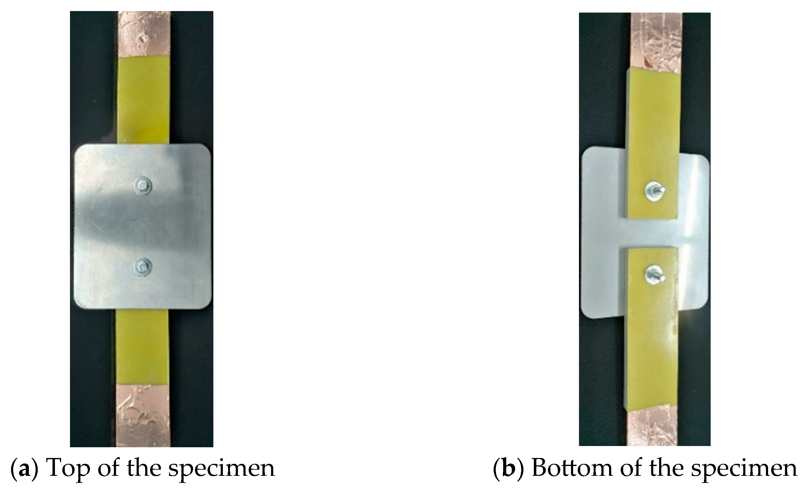
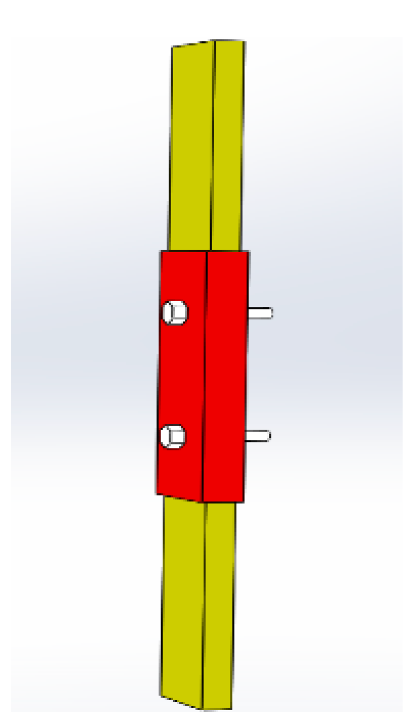
To study the dry band formation process that causes arc discharge at the rod–plate connection, two small-size simplified rod–plate connections are made, which consist of a combination of two composite rods and a square plate (metal or composite). The rods and plates are connected to each other by metal bolts. The node connection of the composite pole tower is quite complex, so a reasonable arrangement is needed to connect many composite rods tp the plate. Considering the influence of thermal expansion of the composite rods, the composite rods are installed on the plate with a certain gap reserved. The simplified connection specimens in this paper have a gap of 2 cm between the two rods. There are composite rods connected with a metal plate or composite plate to the composite tower, and there are obvious differences in the local discharge near the two connection plates. So, the connection specimens for the composite plate and metal plate were both made for the artificial pollution test. The physical diagram of the metal plate connection model is shown in Figure 2. The dimensional parameters of the rod–plate connection are shown in Table 1.
Applied evenly on the outer surface of the connection was 0.2 mg/cm2 ESDD (equivalent salt deposit density) and 2 mg/cm2 NSDD (non-soluble deposit density) of dirt. The fog generator was made to continuously output fog into the fog chamber at a rate of 300 mL/h. The fog generator was stopped when a film of water was observed to form on the specimen surface and droplets were observed to start falling from the edges of the specimen. Then, the water vapor in the fog chamber was drained to control the air humidity in the fog chamber to be the same as the ambient humidity in the laboratory. Thereafter, the characteristic parameters of the infrared, visible light, and leakage current of the dry band discharge process at the connection was observed simultaneously, during the application of a 50 Hz voltage with an amplitude of 500 V to the specimen.

2.3. Test Results

The visible image and infrared temperature distribution when the voltage is applied to the connection of the composite plate are shown in Figure 3. The moment when the voltage starts to be applied is set to 0 s. From the results, it can be seen that there is a partial temperature rise near the metal bolts and the rod–plate interface area, among which the heating in the rod–plate interface area is the most serious. The highest temperature in the interface area reaches 60 °C at 20 s. At 40 s, the dry band discharge is formed in the rod–plate interface area.
The visible image and infrared temperature distribution during voltage application are shown in Figure 4. From the results, it can be seen that the metal plate with metal bolts can be regarded as a whole float potential metal, and there is almost no heating phenomenon. The temperature rise at the rod–plate interface is more significant, and the highest temperature at the edge of the composite rod reaches 80 °C at 20 s, a dry band is formed at 29 s, and a more intense dry band discharge phenomenon is observed.

3. Current Density Simulation

To further investigate the causes of partial discharge at the rod–plate connection in the composite towers, the electric field simulation of the rod–plate connection under wet and dirty conditions is carried out in this paper. Combining the test and simulation results, rod–plate connection structures that are conducive to suppressing the partial discharge phenomenon can be proposed.

3.1. Original Simulation Model of Rod–Plate Connection

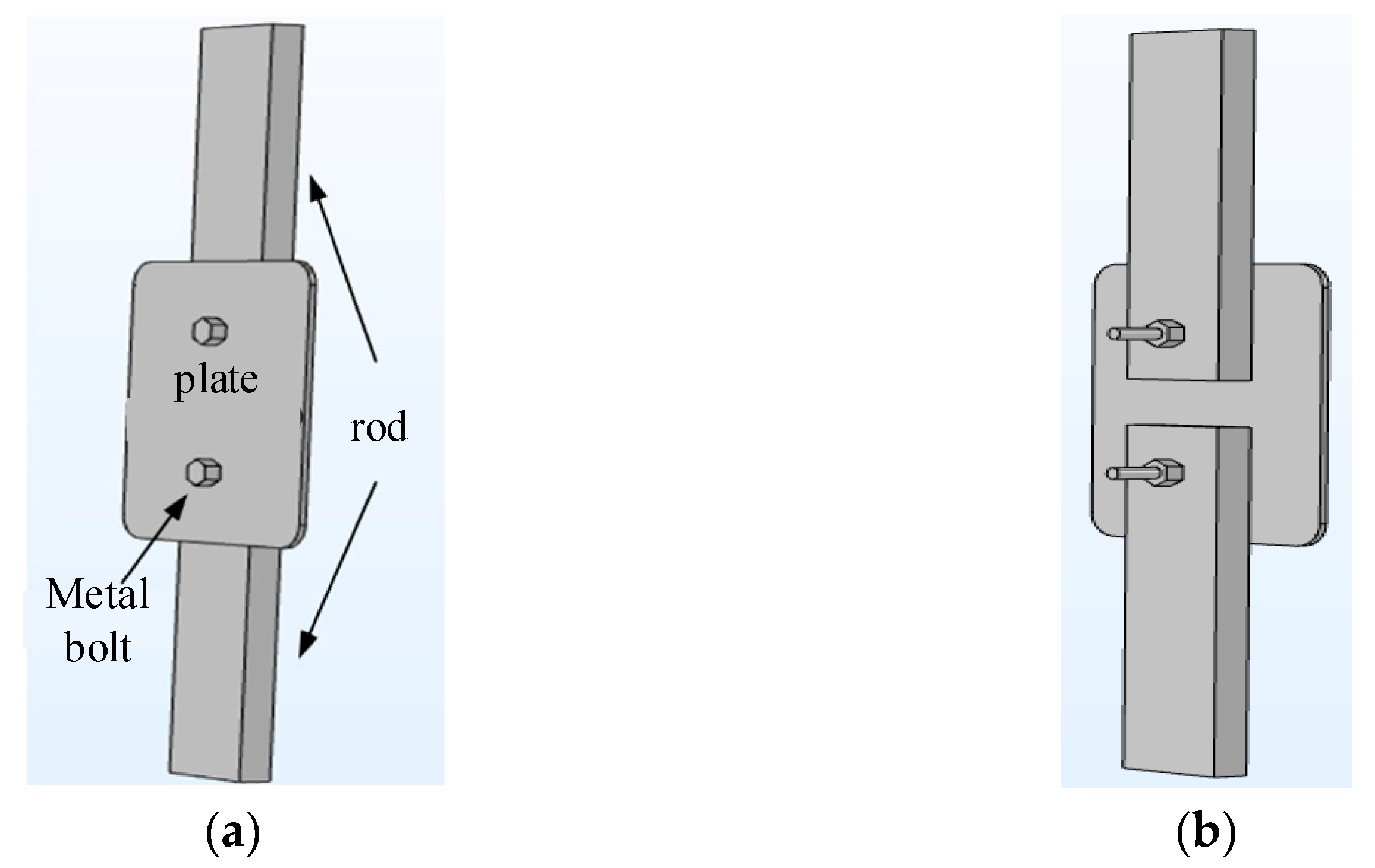
A three-dimensional rod–plate model with the same dimensions as the original test specimen is created, as shown in Figure 5. The outer surfaces of both the rod and plate are set as conductive thin layers to simulate the wet polluted layer. The geometric modeling of the polluted layer is omitted. The material parameters are assigned to the outer surface of the model directly: the thickness of the fouling layer is set to 0.5 mm, and the bolts are hexagonal. The dimensional parameters of the model are shown in Table 1.
To establish the current field, the initial value of electric potential of the model was set to 0. Ref. [12] obtained the electric field for the rod–plate connection near the ground wire cross-arm with the composite material tower under a DC voltage of 100 kV through simulation, which provides a reference for this study. To ensure that the small-sized rod–plate connection specimen has a similar voltage gradient, an AC potential of 500 V is applied to one end of the composite connecting rod, and the end of the other composite rod is set to 0 potential. To establish the heat transfer field, the Joule heat of the current is set as the heat source using the electrothermal coupling principle. The resistivity of the dirt layer is set to vary with temperature according to the experimental measurement results, and the resistivity temperature coefficient is set to −0.0154. The convection heat dissipation of the air is considered on the outer surface of the model, and the heat transfer coefficient is set to 5 W/(m2·K). The initial temperature of the model and the external ambient temperature are set to 20 °C. The electrothermal parameters of the model are shown in Table 2. Some electrothermal parameters are measured according to the references [19,20,21].
The mesh type is selected as free tetrahedron, and the mesh cell size is set as extremely fine. The transient solution is performed for the model before and after the suppression measure, so the effectiveness of the suppression measure is compared and analyzed according to the distribution of the electrothermal parameters after 4 s of applied voltage.
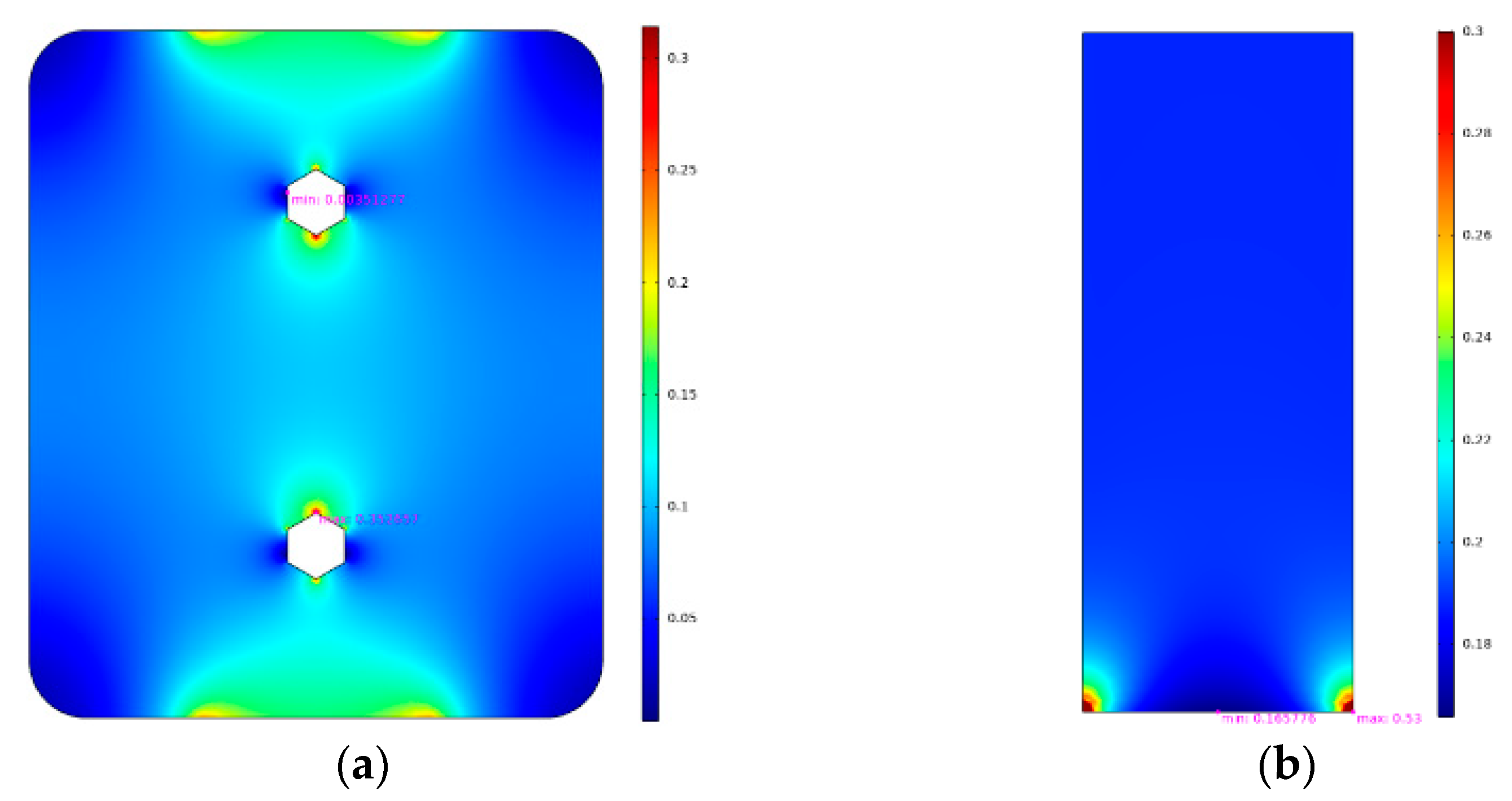
The current density distribution on the surface of the connection model of the composite plate before improvement is shown in Figure 6. From the results, it can be seen that the current density is higher near the metal bolts on the composite plate and at the interfaces with the composite rod. The result is consistent with the heating area in the artificial pollution test, indicating that the local temperature rise is caused by the current density distortion. The partial discharge in the artificial pollution test on the tower also occurs at the interfaces with the composite rod, which also confirms the theory that the concentration of current density on the surface of the tower leads to the formation of a dry band, which in turn triggers the partial discharge.
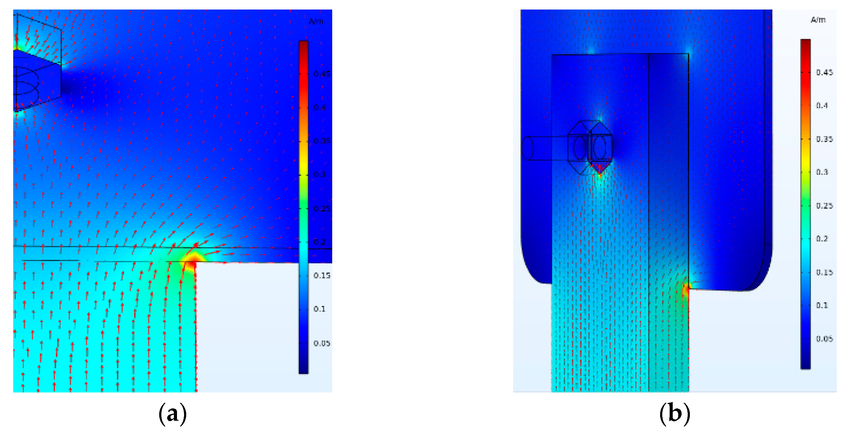
The flow direction of the current density vector can indicate the cause of the current density distribution distortion. With the arrow length representing the current density value and the arrow direction indicating the direction of the current density vector, the current density diagram on the surface of the composite plate connection model before improvement is shown in Figure 7. The direction of red arrow represents the direction of the current.
From the results, it can be seen that the current is concentrated near the bolts, which leads to the distortion of the current density near the bolt. Due to the existence of gaps between the two composite rods, the current beside the composite rod flows toward the composite plate. The current on the top of the composite rod and the composite plate has a tendency to flow toward the edge, thus causing the concentration of the current density at the interfaces of the rod and plate. Especially at the point where the edge of the composite rod and the composite plate meet, there is a serious distortion of the current density.
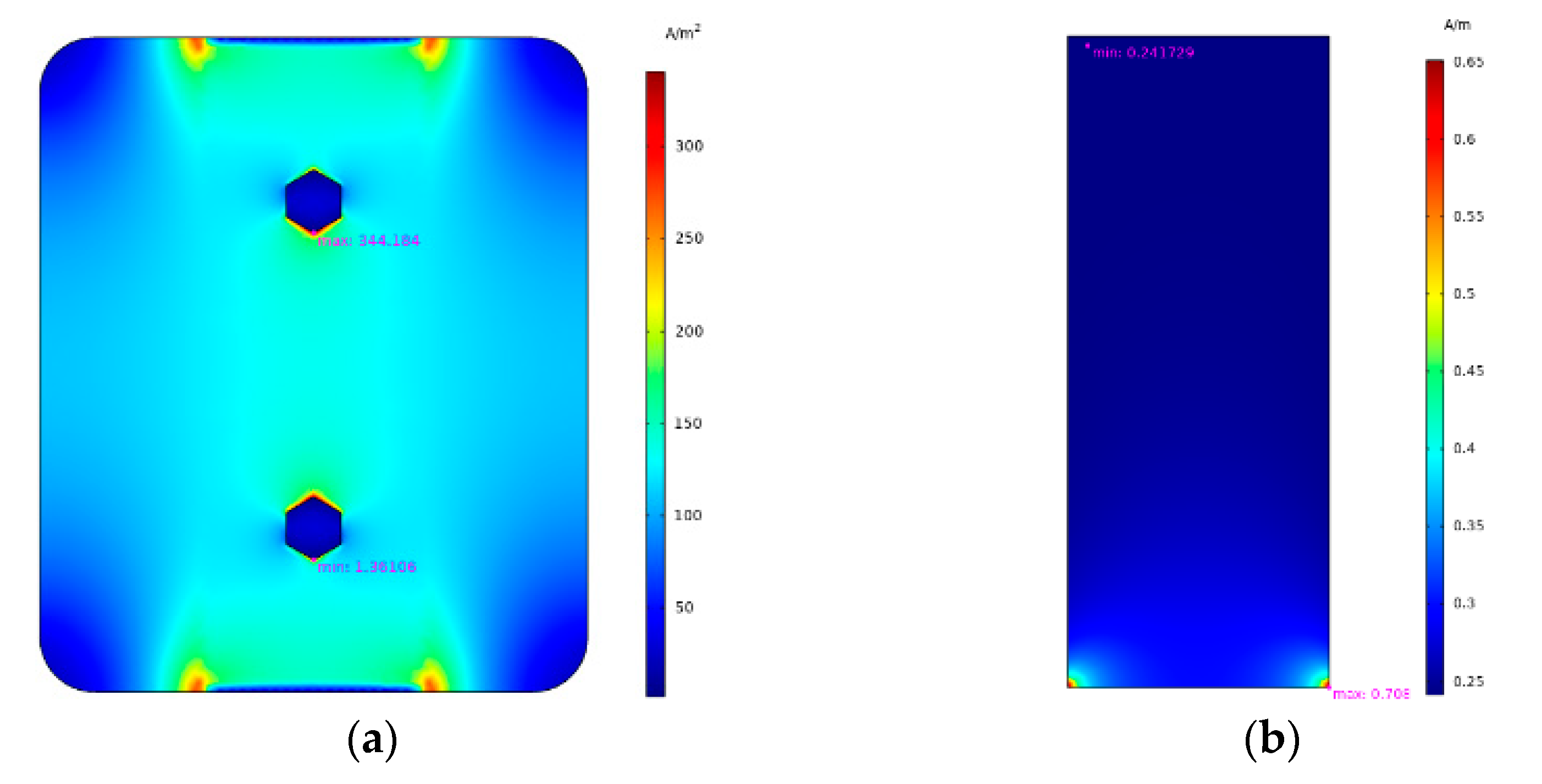
For the partial discharge problem on the metal connection plate, the simplified metal plate connection model is established and the electro-thermal coupling transient simulation is conducted. The current density distribution at 4 s on the metal plate and composite rod surface is shown in Figure 8. As can be seen from the results, the current density at the interfaces of the metal plate and composite rod articulation is larger, of which the current density at the two outer side points of the interfaces is the most concentrated. The maximum surface current density reaches 0.708 A/m.
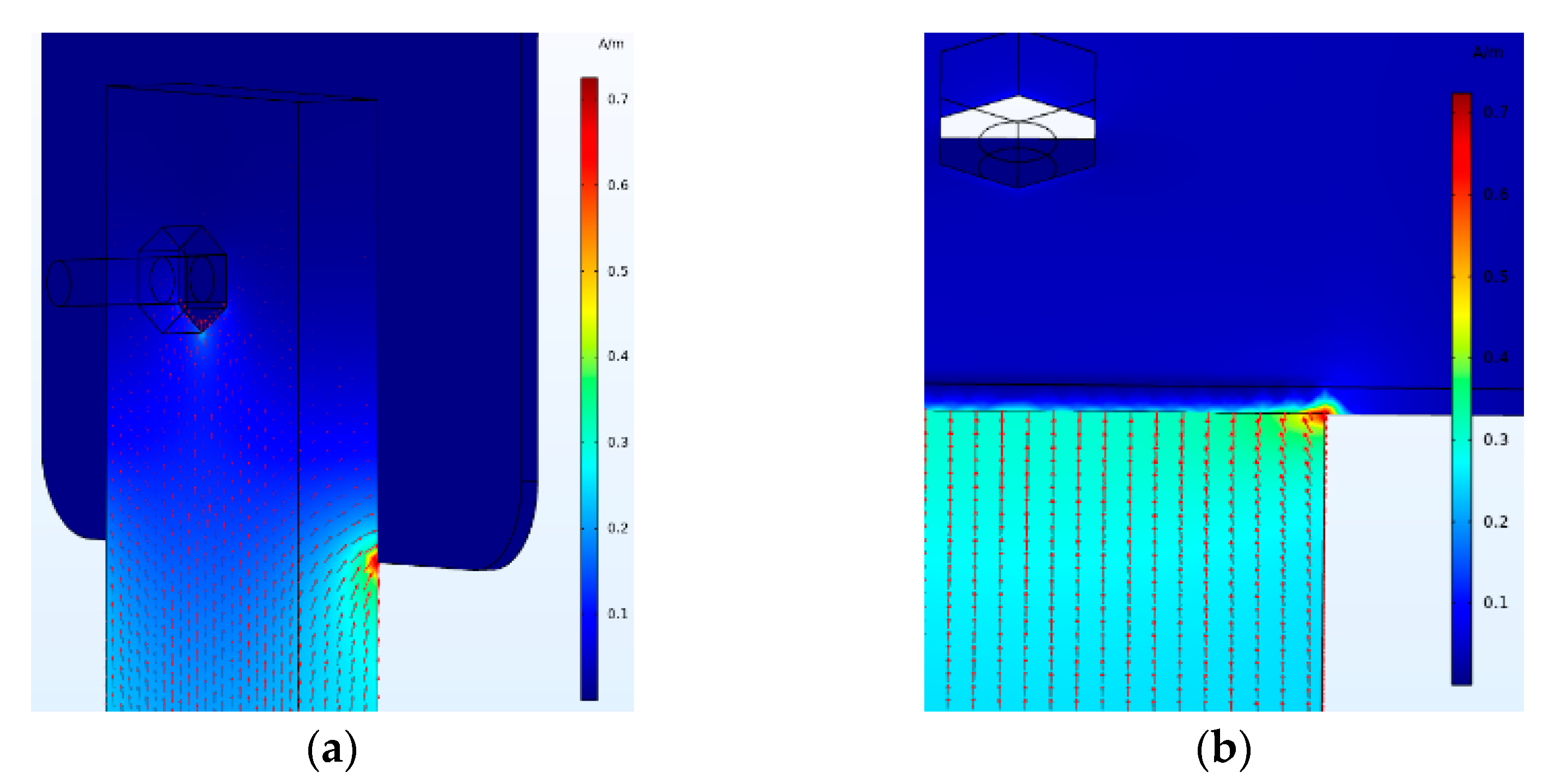
The surface arrow diagram of the current density vector at the connection of the metal plate is shown in Figure 9. The direction of red arrow represents the direction of the current. Through the figure, it can be obtained that the current density distribution on the top of the model is relatively uniform, due to better conductivity than the composite plate. The trend of the current under and beside the rod flowing to the metal plate and the metal bolts is stronger than that of the composite plate, leading to the current density distortion near the rod–plate articulation point and the bolt at the bottom of the composite rod.
According to the simulation, targeted improvement measures are needed to suppress the current density distortion phenomenon for the two rod–plate connections, respectively.

3.2. Current Density Simulation of Improved Composite Plate Connection Structure

According to the simulation results in Section 3.1, in order to avoid the current concentration at the articulation points, the width of the composite plate is changed to be the same as the composite rod, and the end of the composite plate is changed to become rounded to increase the length of the rod–plate articulation area. The improved connection structure is shown in Figure 10.
The electro-thermal coupling simulation of the improved composite plate connection is carried out, and the current density distribution at 4 s is obtained as shown in Figure 11. From the results, it can be seen that the current density distribution in the rod–plate articulation area becomes very uniform after adopting the improved composite plate structure, and the current density distortion at the edge of the composite rod is suppressed. According to the analysis in Section 3.1, the dry band formation process is mainly related to the current density maximum of the polluted layer, so the effect of the suppression measure is measured by comparing the current density maximum before and after the improvement of the connection model.
The maximum current density on the composite rod decreases from 0.54 A/m to 0.16 A/m. The thickness of the fouling layer is 0.5 mm, so the body current density in the polluted layer decreased from 1080 A/m2 to 318 A/m2. However, the current density distortion near the metal bolts on the composite plate become more severe, and the maximum current density near the bolts increases from 0.35 A/m to 0.55 A/m, and the body current density in the polluted layer increases from 700 A/m2 to 1100 A/m2. The main reason may be that the reduction in the width of the composite plate leads to a larger partial voltage and, thus, to a higher current density near the bolts, while the voltage at the connection of the rod–plate remains unchanged. The simulation results show that the improvement measure can effectively improve the current density distribution in the rod-plate connection area, but increase the current density near the bolts, and do not play an overall role in suppressing the current density distortion at the composite plate connection.
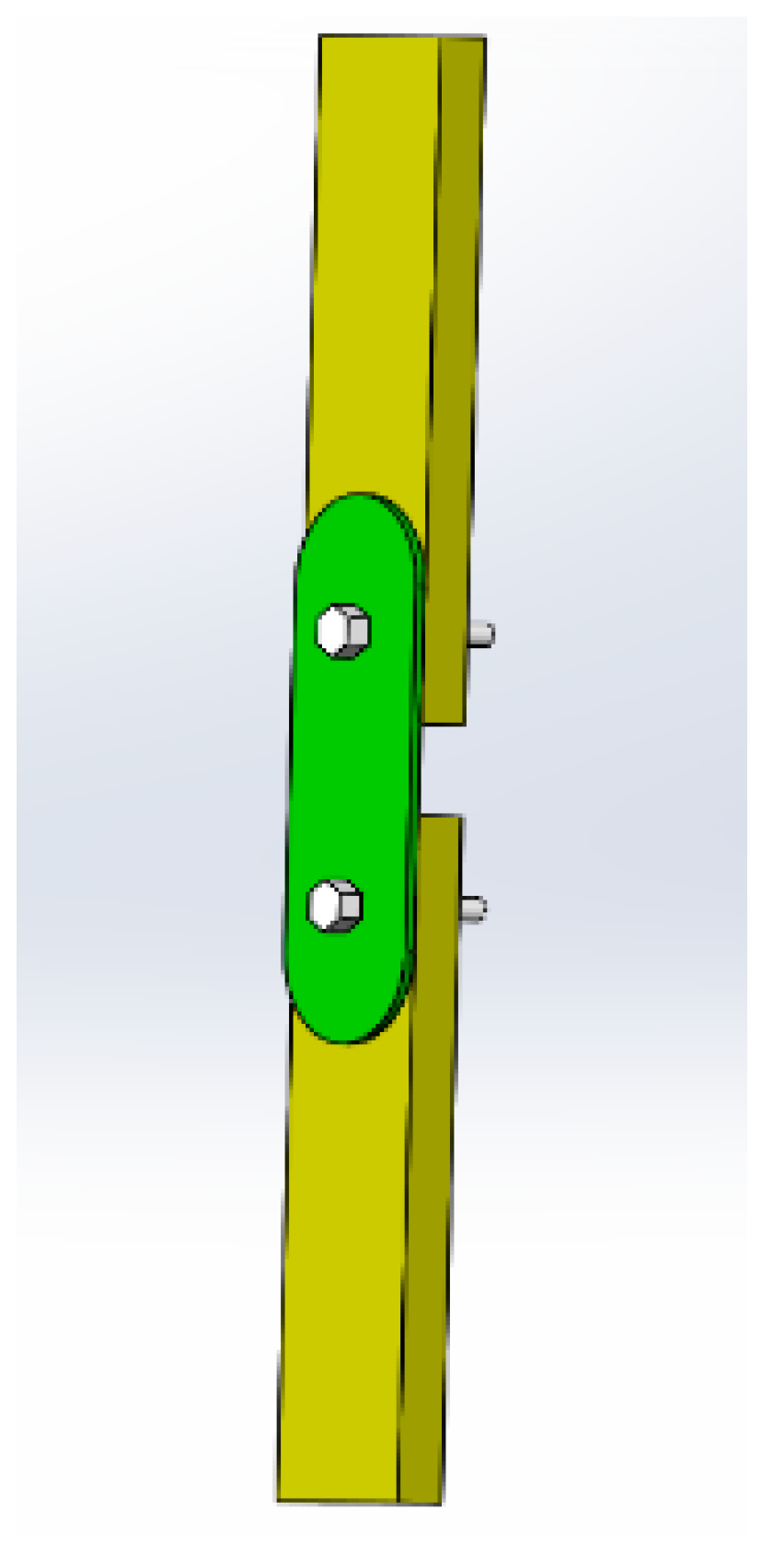
To address the current density distortion near the bolts and the rod–plate articulation area, from the perspective of increasing the contact area of the bolt and the composite connection plate to make the connection structure more symmetrical, the measure of connecting the round composite plate in parallel is proposed. The hexagonal round bolts are used instead, and the composite rod is chamfered to improve the current density distortion near the bolts and the articulation points of the composite rods. The improved connection structure is shown in Figure 12.
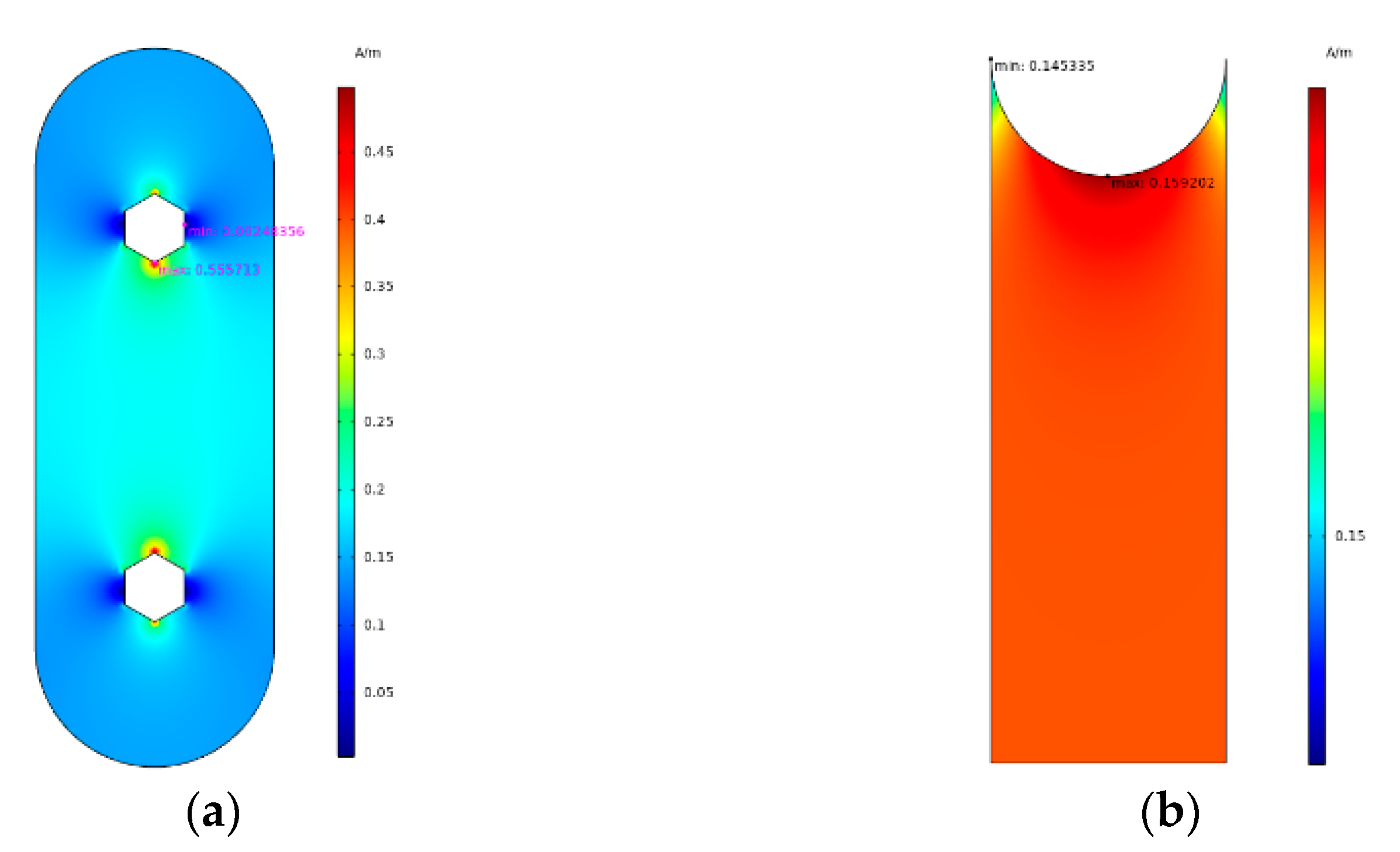
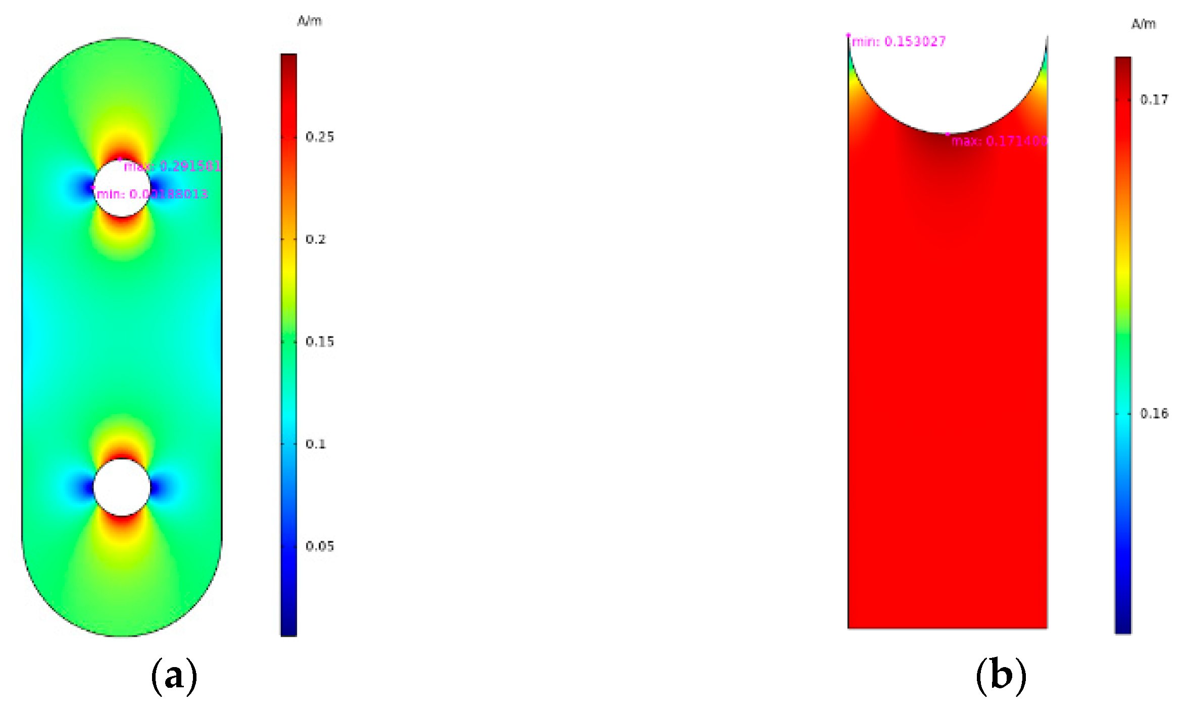
The electro-thermal coupling simulation is carried out for the improved parallel round composite plate, and the current density distribution at 4 s is obtained as shown in Figure 13. As can be seen from Figure 13, the maximum current density near the metal bolt is reduced to 0.29 A/m, and the body current density of the polluted layer is equivalent to 580 A/m2. The current density distribution characteristics of the rod–plate articulation area are basically the same as that of a single composite plate, and the maximum current density is slightly increased, mainly because the equivalent resistance of the connection point is reduced after the parallel connection of the composite plate, resulting in the increase in the current density on the composite rod.
The maximum current densities for the rod–plate model before the improvement and for the model with the two improvement measures are shown in Table 3. From the table, it can be seen that the current density at the rod–plate articulation point is the smallest in the connection form of a single round composite plate, but the current density near the bolt is greater than before the improvement. However, the current density near the bolt is significantly reduced in the connection form involving the parallel round composite plate, and also the current density distortion near the rod–plate connection is also suppressed by adopting the parallel round composite plate. In a comprehensive comparison, the parallel round composite plate connection form has a better suppression effect on the current density distortion.

3.3. Simulation of Improved Metal Plate Connection Structure

In the composite tower, the metal plate as a whole can be regarded as a float potential body. To improve the current density distortion near the bolts at the edge and bottom of the composite rod, the form of the metal plate connection is changed to a metal sleeve form to increase the contact area between the metal plate and the composite rod, so that the connection structure is also more symmetrical. The schematic diagram of the metal sleeve connection form is shown in Figure 14.
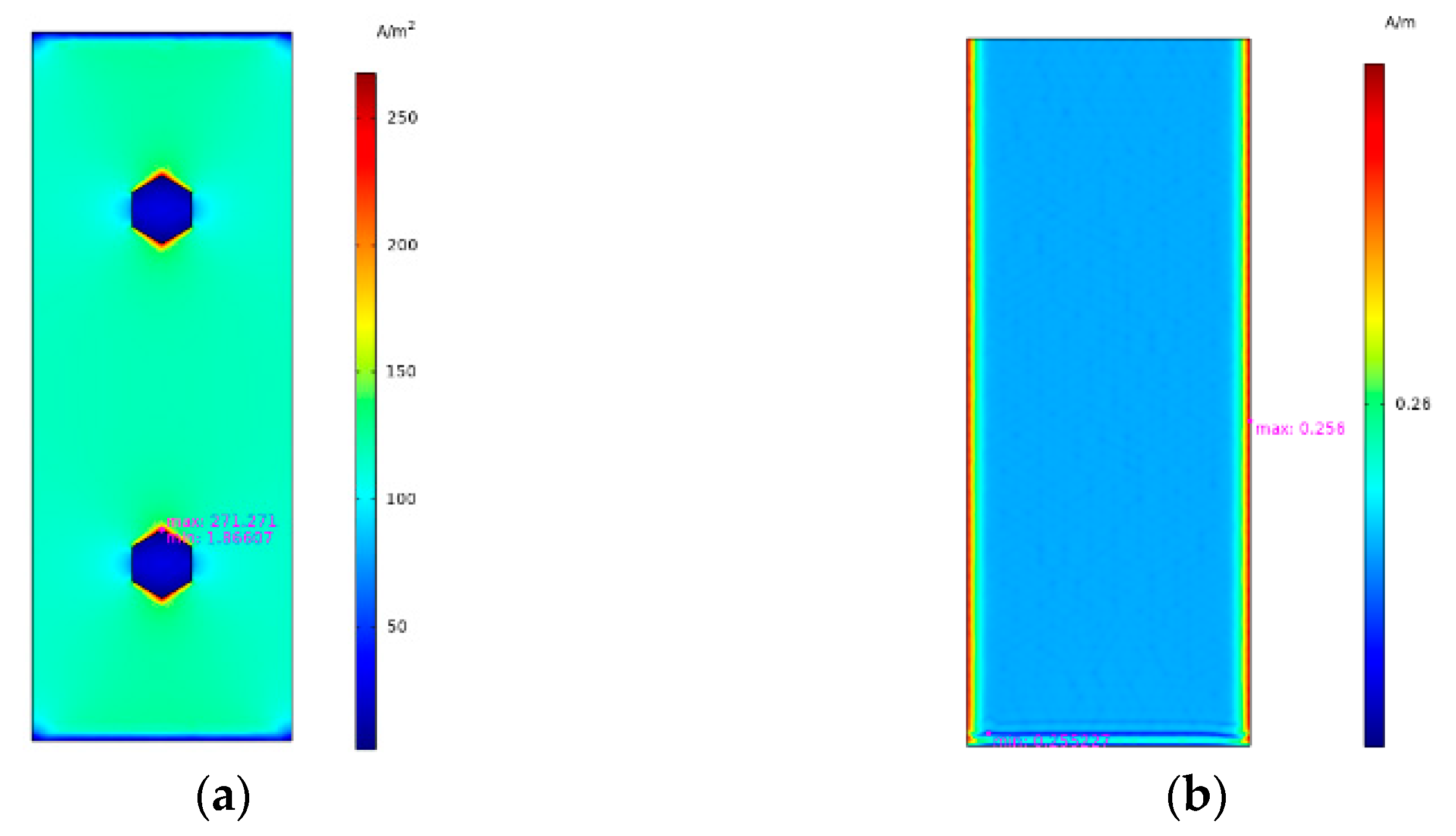
The simulation model for the connection of the metal sleeve form is established, and the electro-thermal coupling transient calculation is carried out. The current density distribution on the surface of the connection point at 4 s is obtained as shown in Figure 15. Comparing the current density cloud map before and after the improvement, it can be seen that the current density on the top of the metal plate is reduced and the distribution becomes more uniform. Based on the dry band formation mechanism [13], the maximum value of the current density is used to evaluate the suppression effect of the improvement measures. The maximum current density of the metal plate connection before and after the improvement is shown in Table 4. The maximum current density of the metal connection plate is reduced from 344 A/m2 to 271 A/m2. The current density maximum on the surface of the composite rod is reduced from 0.708 A/m to 0.256 A/m, which is converted into the body current density in the polluted layer, equivalent to a reduction from 1416 A/m2 to 512 A/m2. It shows that the improvement measures effectively reduce the maximum current density at the connection, which helps to suppress the dry band formation.

4. Validation Test and Discussions

The same test procedure, as in Section 2, is used to obtain the dry band formation time, partial discharge phenomenon, and leakage current value. Comparing these features with the situation before the improvement, the effectiveness of the measures can be verified.

4.1. Validation Test for the Improved Composite Plate

The single round composite plate structure was tested, and the visible image and infrared temperature image during the applied voltage are shown in Figure 16. From the results, it can be seen that the local temperature rise in the rod–plate articulation area, especially at the edge of the composite rod, is suppressed after the structure change. However, the heat generation near the metal bolt becomes more serious than before the change, and the maximum temperature near the bolt reaches 73 °C at 20 s. After applying the voltage for 30 s, dry bands are formed both at the rod–plate articulation and in the area between the two bolts. Although the single round composite plate suppresses the local temperature rise in the rod–plate articulation area to some extent, it exacerbates the local temperature rise near the bolts instead. Compared with the composite plate connection before the improvement, the dry band formation time is shortened by 10 s. It shows that the round composite plate connection form is not enough to improve the temperature distribution at the connection and suppress the dry band formation.
The parallel round composite plate model is also tested, and the visible images and infrared temperature images during the applied voltage are shown in Figure 17. From the images, it can be seen that after adopting the improvement measures to the parallel round composite plate, the local heating phenomenon near the metal bolts basically disappears, and the temperature distribution at the edge of the composite rod becomes more uniform. The speed of the local temperature rise at the rod–plate articulation is significantly reduced, and the highest temperature only rises to 45 °C when the voltage is applied for 20 s. The dry band is formed at the rod–plate articulation only when it reaches 75 s, and the formation time is 35 s later than the connection form before the improvement. Moreover, the dry band discharge is relatively weak. It shows that the improvement measures to the parallel round composite plate effectively improve the temperature distribution at the connection and suppress the formation of the dry band.
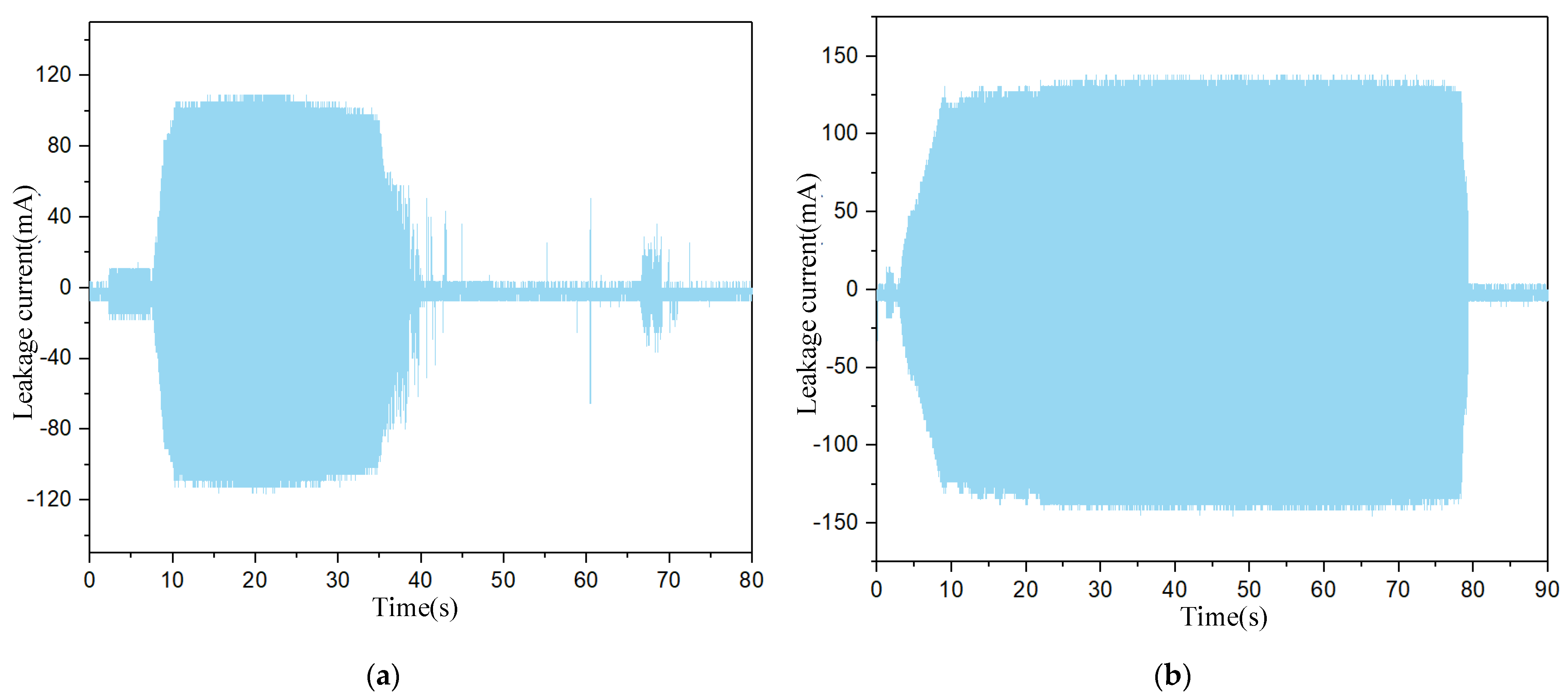
The waveforms of the leakage current during the application of the voltage to the connection models for the single round composite plate and the parallel round composite plate are shown in Figure 18. It can be seen from Figure 18 that after changing the connection plate form to the parallel round composite plate, the leakage current at the connection point increases from 109 mA to 136 mA, due to the reduction in the equivalent resistance of the connection, but the formation time of the dry band increases from 30 s to 75 s. After the formation of the dry band, the number of local discharge pulses in the leakage current waveform for the single circular composite plate increases, while the parallel composite plate has no obvious discharge pulses. This indicates that the partial discharge for the single round composite plate is more severe, while the partial discharge for the parallel round composite plate is suppressed.

4.2. Validation Test for the Improved Metal Plate

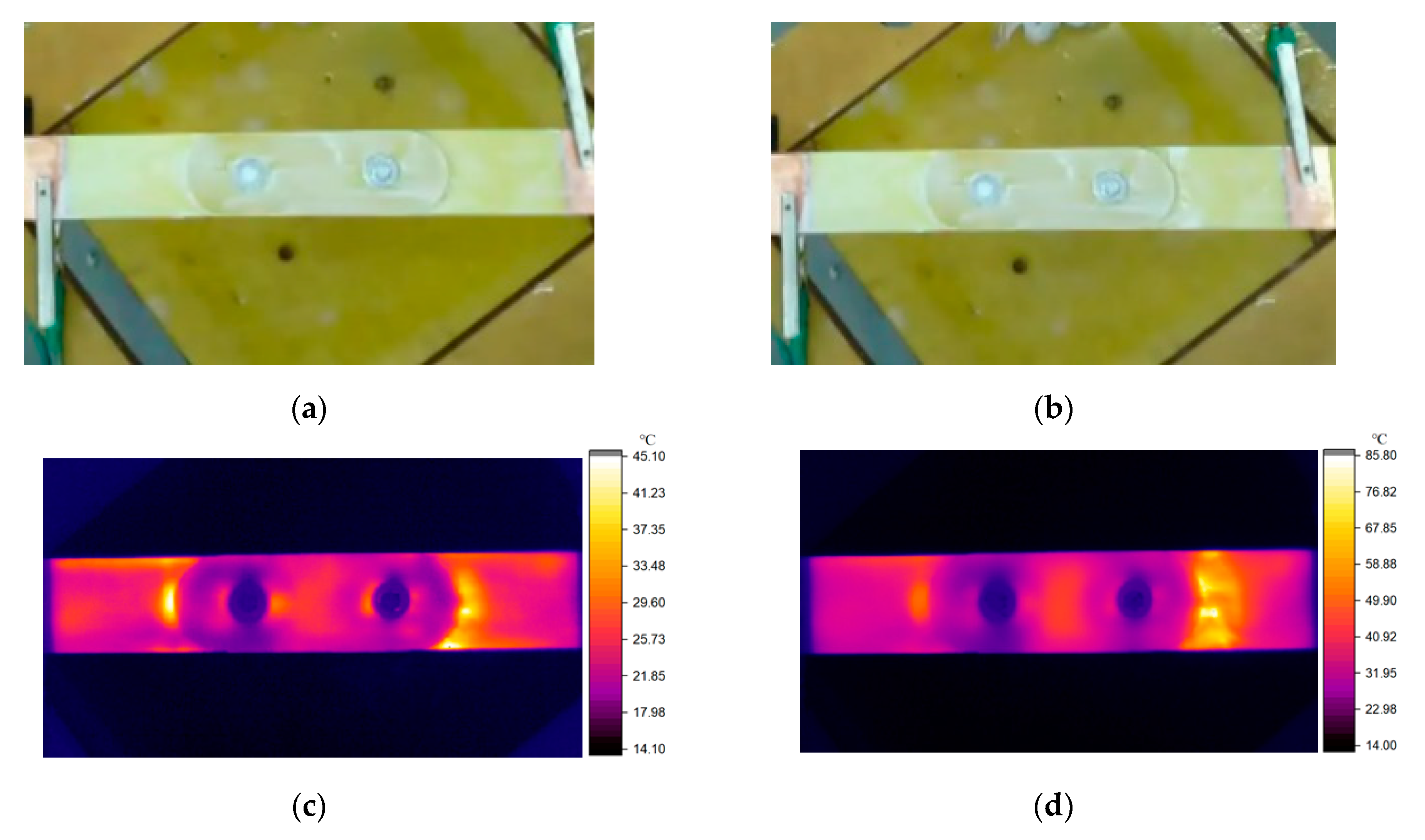
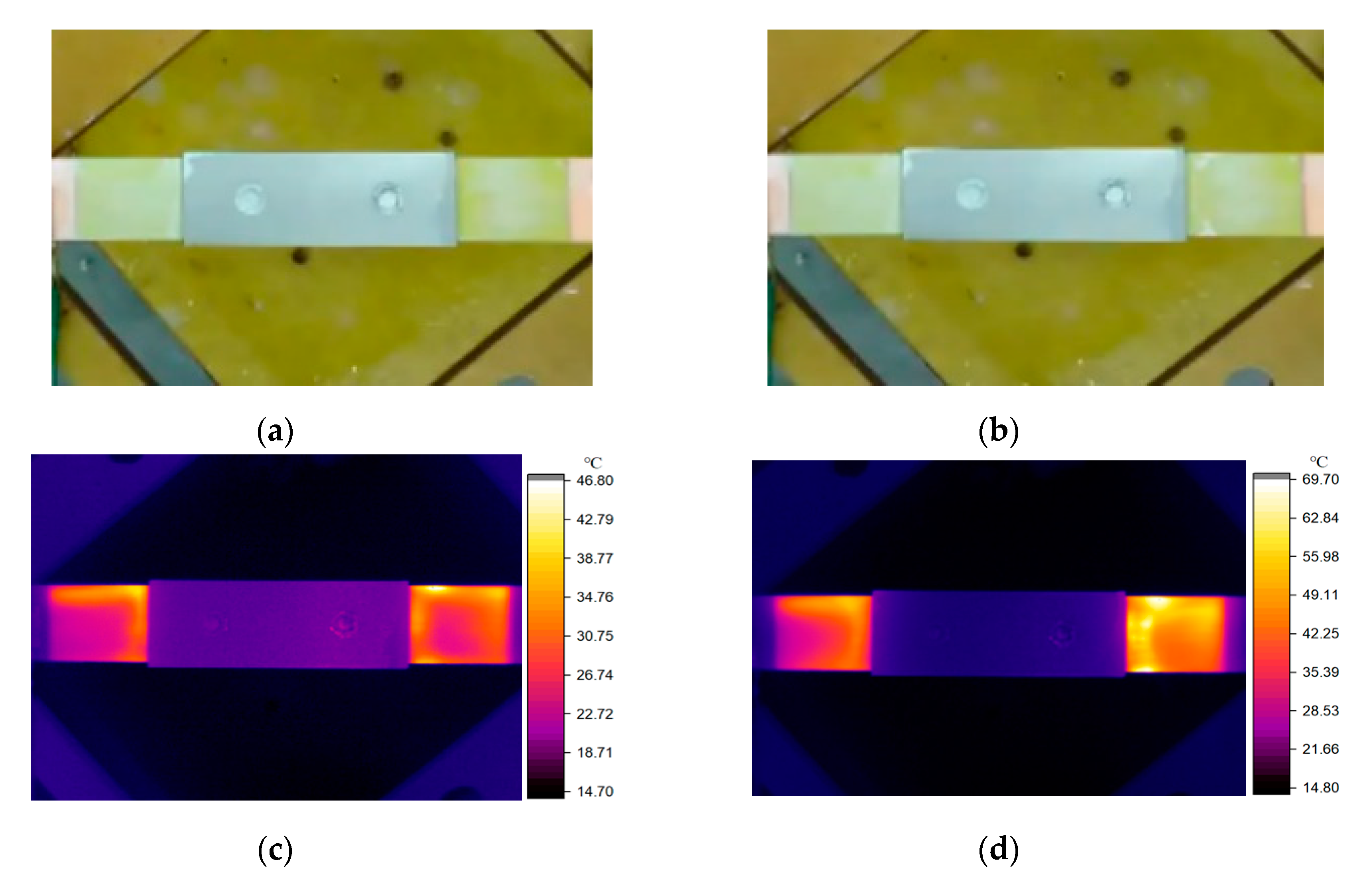
The metal sleeve connection model is tested, and the visible light images and infrared temperature images during the applied voltage are shown in Figure 19. As can be seen from the images, after changing to the metal sleeve connection form, the temperature distribution on the surface of the composite rod becomes more uniform, and the temperature rise rate of the polluted layer is also significantly reduced. The maximum surface temperature is only 46 °C at 20 s of the applied voltage, and the dry band is formed in the rod–plate articulation area only after 46 s of the applied voltage. The formation time is increased by 17 s compared with the metal plate form. Moreover, no significant partial discharge is observed when the dry band penetrates the polluted layer. It shows that the metal sleeve connection form effectively improves the temperature distribution at the connection and plays a role in inhibiting the formation of the dry band.
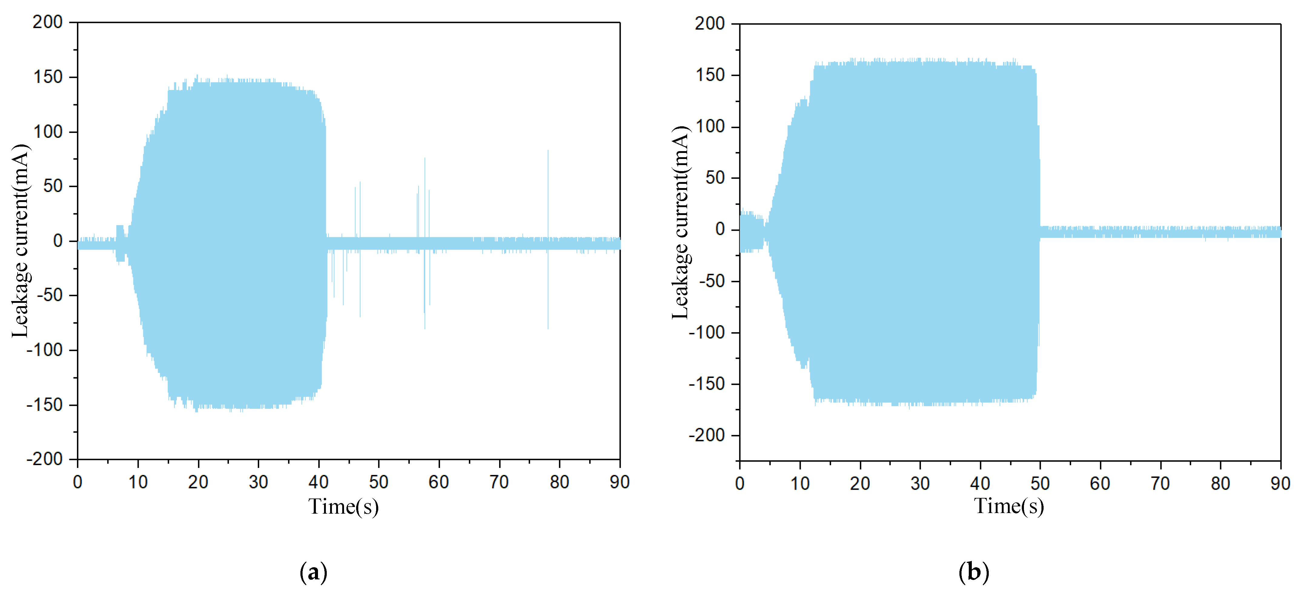
The waveforms of the leakage currents for the metal plate and metal sleeve connection during the application of voltage are shown in Figure 20. From the results, it can be seen that after changing to the metal connection form, due to the larger contact area between the metal sleeve and the composite rod, the amplitude of the leakage current increases from 147 mA to 167 mA. However, the dry band formation time increases from 29 s to 46 s. The original metal plate connection has more discharge pulses in the leakage current waveform, while the improved metal sleeve connection has almost no discharge pulses, indicating that the metal sleeve connection can indeed play a role in suppressing the partial discharge.

5. Conclusions

(1)
For the original composite plate connection, there is a local temperature rise near the metal bolt and rod–plate articulation area, and the rod–plate articulation area experiences the most serious heating effect. For the original metal plate connection, the metal plate itself, as a whole, as a suspended potential body has almost no heating phenomenon, but the rod–plate articulation temperature rise is more significant;
(2)
For the composite plate connection, a parallel round composite plate connection form is proposed as an improvement measure. The parallel round composite plate increases the rod–plate articulation area, makes the edges that cause the current field distortion more smooth, so that the current density distribution is more uniform. Therefore, the current density near the bolt also decreases;
(3)
The improvement measure of the metal sleeve is proposed for the connection of the metal plate. After the connection of the metal plate is changed into the form of the metal sleeve connection, the current density distortion in the junction area of the composite rod and metal part is suppressed because the contact surface perimeter of the connection is increased, and the structure is well-proportioned. The temperature rise of the improved connection is significantly slowed down, the dry band formation time is also significantly increased, and the dry band discharge intensity is also weakened, which proves that the improvement measures can effectively suppress the local temperature rise and dry band formation.

Author Contributions

Conceptualization, J.H. (Jinpeng Hao) and J.H. (Jinzhu Huang); methodology, Z.F.; validation, X.H. and Q.W.; formal analysis, Q.W.; investigation, X.H.; resources, H.W.; data curation, X.G.; writing—original draft preparation, X.H.; writing—review and editing, Y.W.; visualization, X.G.; supervision, Y.W.; project administration, J.H. (Jinpeng Hao); funding acquisition, H.W. All authors have read and agreed to the published version of the manuscript.

Funding

This research and the APC were funded by the Technology Project of State Grid Ningxia Electric Power Co., Ltd., grant number 5229GY220002.

Data Availability Statement

Not applicable.

Conflicts of Interest

The authors declare no conflict of interest.

References

  1. Stewart, R. Pultruded Poles Carry Power. Reinf. Plast. 2003, 47, 20–24. [Google Scholar] [CrossRef]
  2. Ramirez-Vazquez, I.; Hernández-Corona, R.; Salgado-Talavera, J.E. Composite Materials As an Alternative to Replace Steel Members on Lattice Power Transmission Towers. J. Mater. Civ. Eng. 2016, 28, 04015151. [Google Scholar] [CrossRef]
  3. Lin, Y.; Huchang, W.; Xueling, Z. Application Research of FRP in the Transmission Structures. Electr. Power 2014, 47, 53–56. [Google Scholar]
  4. Zhijun, L.; Weijiang, C.; Tong, Z.; Min, D.; Wendong, J.; Cancan, W.; Zongxi, L. Electrical Structure Design of Lattice Composite Material Tower of 110 kV Double Circuit Transmission Line. Power Syst. Technol. 2015, 39, 536–542. [Google Scholar]
  5. Lei, Z.; Mingzhu, Z.; Yabo, L.; Huadong, L.; Chaokai, T.; Zhaoyin, S.; Zhiwei, W. Structure Analysis of Carbon Fiber Reinforced GFRP Transmission Tower. Eng. Plast. Appl. 2018, 46, 95–100. [Google Scholar]
  6. Alshurafa, S.; Polyzois, D. Design Recommendations and Comparative Study of FRP and Steel Guyed Towers. Eng. Sci. Technol. Int. J. 2018, 21, 807–814. [Google Scholar] [CrossRef]
  7. Valdez, A.H.; Vázquez, I.R.; Corona, R.H.; Vazquez, J.V.; Noyola, D.P.; Luisillo, A.B.; Hurtado, C.H.; Silva, A.P. Connection Method Design for Redundant Elements of Composite Materials for Transmission Towers. In Proceedings of the 2016 IEEE PES Transmission & Distribution Conference and Exposition-Latin America (PES T&D-LA), Morelia, Mexico, 20–24 September 2016; pp. 1–5. [Google Scholar]
  8. Huanhuan, L.; Xiaodong, Z.; Rui, K.; Lijun, Y. FEM Structure Design of 10kV Composite Transmisson Tower and The Application Study of Engineering. Fiber Reinf. Plast. Compos. 2015, 330, 69–73. [Google Scholar]
  9. Sihua, W.; Junjun, W.; Lei, Z.; Long, C. Influence of Pollution Components on Surface Electric Field of Composite Insulators. Electr. Power 2021, 54, 149–157. [Google Scholar]
  10. Hongwei, M.; Chenlong, Z.; Haiqi, D.; Liming, W.; Zhicheng, G.; Fuzeng, Z. Wetting Characteristics of Contaminated Porcelain and Glass Insulators. Proc. Chin. Soc. Electr. Eng. 2014, 34, 1471–1480. [Google Scholar]
  11. Yu, W.; Lin, M.; Wankun, W.; Wei, W.; Huan, P.; Xishan, W.; Lei, L. Research on Characteristics of Partial Electric Arc on Contaminated Insulating Surface Attached With Floating Potential Metal. Proc. Chin. Soc. Electr. Eng. 2019, 39, 3253–3261. [Google Scholar]
  12. Zhijun, L.; Weijiang, C.; Wendong, J.; Cancan, W.; Min, D.; Zongxi, L. Pollution Performance of Lattice Composite Material Tower of 110 kV Double Circuit Line. High Volt. Eng. 2015, 41, 1320–1327. [Google Scholar]
  13. Lan, L.; Mu, L.; Wang, Y.; Wang, W.; Fu, Z.; Wen, X. Study on Dry Band Discharge of Wet Polluted Surface with Float Potential Metal by Electro-Thermal Synchronous Observation. IET Sci. Meas. Technol. 2020, 14, 789–796. [Google Scholar] [CrossRef]
  14. Andoh, M.-A.; Gbah, K.; Volat, C. Development of a Simple Experimental Setup for the Study of the Formation of Dry Bands on Composite Insulators. Energies 2022, 15, 5108. [Google Scholar] [CrossRef]
  15. Slama, M.E.A.; Albano, M.; Haddad, A.M.; Waters, R.T.; Cwikowski, O.; Iddrissu, I.; Knapper, J.; Scopes, O. Monitoring of Dry Bands and Discharge Activities at the Surface of Textured Insulators with AC Clean Fog Test Conditions. Energies 2021, 14, 2914. [Google Scholar] [CrossRef]
  16. Zhang, D.; Meng, F. Research on the Interrelation between Temperature Distribution and Dry Band on Wet Contaminated Insulators. Energies 2019, 12, 4289. [Google Scholar] [CrossRef]
  17. Nouir-Masmoudi, H.; Dhahbi-Megriche, N. Effect of Pollution Layer Discontinuity Due to the Dry Bands Presence on Potential and Electric Field along Insulator. In Proceedings of the 2022 5th International Conference on Advanced Systems and Emergent Technologies (IC_ASET), Hammamet, Tunisia, 22–25 March 2022; IEEE: Hammamet, Tunisia, 2022; pp. 233–238. [Google Scholar]
  18. Lijun, J.; Zhiren, T.; Kai, G.; Rong, X. Discrimination of Insulator Contamination Grades Using Information Fusion of Infrared and Visible Images. Proc. Chin. Soc. Electr. Eng. 2016, 36, 3682–3691. [Google Scholar]
  19. Zhicheng, Z.; Chenlong, Z.; Song, G.; Mingmin, W.; Yang, L.; Fengbo, T.; Liming, W. Analysis on Wetting and Conductive Properties of Natural Polluted Insulators. High Volt. Eng. 2014, 40, 3680–3687. [Google Scholar]
  20. Yi, S. Contamination Degree Evaluation Model for Insulator Based on Surface Polluted Layer Conductivity. High Volt. Appar. 2014, 50, 106–110. [Google Scholar]
  21. Liming, W.; Bo, Z.; Xiaobo, M.; Hongwei, M.; Zhicheng, G.; Jun, Z. Experimental Study on Streamer Discharge Characteristics Along Contamination Insulator Surface. High Volt. Eng. 2014, 40, 972–978. [Google Scholar]
Figure 1. Artificial pollution test platform.
Energies 16 03712 g001
Figure 2. Metal plate connection.
Energies 16 03712 g002
Figure 3. Visible images and infrared temperature maps for the composite plate connection point: (a) visible light 20 s, (b) visible light 40 s, (c) infrared light 20 s, (d) infrared light 40 s.
Energies 16 03712 g003
Figure 4. Visible images and infrared temperature maps for the metal plate connection: (a) visible light 20 s, (b) visible light 40 s, (c) infrared light 20 s, (d) infrared light 40 s.
Energies 16 03712 g004
Figure 5. Simulation model of rod–plate connection before improvement: (a) top of the model and (b) bottom of the model.
Energies 16 03712 g005
Figure 6. Current density distribution for the composite plate and composite rod connection: (a) composite plate surface and (b) composite rod surface.
Energies 16 03712 g006
Figure 7. Current density vector diagram for the composite connection plate: (a) top of the model and (b) bottom of the model.
Energies 16 03712 g007
Figure 8. Current density distribution for the metal plate connection model: (a) top of the model and (b) bottom of the model.
Energies 16 03712 g008
Figure 9. Current density vector diagram for the metal plate connection model: (a) front side of the model and (b) back side of the model.
Energies 16 03712 g009
Figure 10. Improved composite plate.
Energies 16 03712 g010
Figure 11. Current density distribution for the improved composite plate: (a) composite plate surface and (b) composite rod surface.
Energies 16 03712 g011
Figure 12. Parallel round composite plate.
Energies 16 03712 g012
Figure 13. Current density distribution for the parallel round composite plate connection; (a) composite plate surface and (b) composite rod surface.
Energies 16 03712 g013
Figure 14. Metal sleeve.
Energies 16 03712 g014
Figure 15. Current density distribution at the connection of the improved metal plate: (a) metal sleeve surface and (b) composite rod surface.
Energies 16 03712 g015
Figure 16. Visible light images and infrared temperature maps of the connection of the single round composite plate: (a) visible light 20 s, (b) visible light 40 s, (c) infrared light 20 s, (d) infrared light 40 s.
Energies 16 03712 g016
Figure 17. Visible light images and infrared temperature maps for the parallel round composite plate connection form: (a) visible light 20 s, (b) visible light 75 s, (c) infrared light 20 s, (d) infrared light 75 s.
Energies 16 03712 g017
Figure 18. Leakage current waveforms: (a) single round composite plate and (b) parallel round composite plate.
Energies 16 03712 g018
Figure 19. Visible light images and infrared temperature maps for the metal sleeve connection form: (a) visible light 20 s, (b) visible light 46 s, (c) infrared light 20 s, (d) infrared light 46 s.
Energies 16 03712 g019
Figure 20. Leakage current waveforms: (a) metal plate and (b) metal sleeve.
Energies 16 03712 g020
Table 1. Dimensional parameters for the specimens.
SortSize/mm
Connection rod150 × 40 × 10
Connection plate120 × 100 × 2
Metal nutThe tangent circle is 10 in diameter and 5 in thickness
Metal screw30 in length and 5 in diameter
Table 2. Electrothermal parameters for the connection point model.
Electrothermal ParametersComposite Plate Composite RodMetal Plate
Metal Sleeve
Nut ScrewContaminated Layer
Conductivity(S/m)2.1 × 10−181 × 1071 × 1070.2
Relative dielectric constant 41 × 1081 × 10820
Perveance(W/(m2·K))0.434004000.55
Density(kg/m3)1673896089601030
Heat capacity at constant pressure(J/(kg·K))10003853852000
Table 3. The maximum current density before and after the improvement of the composite connection plate.
Connection FormCurrent Density A/m2
Connection PointBolt
Original composite plate connection1080700
Single round composite plate connection3181100
Parallel round composite plate connection340580
Table 4. Maximum current density before and after improvement of the metal plate connection structure.
Connection FormCurrent Density A/m2
Connection PointMetal Plate
Metal plate connection1416344
Metal sleeve connection512271
Disclaimer/Publisher’s Note: The statements, opinions and data contained in all publications are solely those of the individual author(s) and contributor(s) and not of MDPI and/or the editor(s). MDPI and/or the editor(s) disclaim responsibility for any injury to people or property resulting from any ideas, methods, instructions or products referred to in the content.