Article

Integrating Prospective Scenarios in Life Cycle Engineering: Case Study of Lightweight Structures

1
Chair of Automotive Lightweight Design (LiA), Institute for Lightweight Design with Hybrid Systems (ILH), Paderborn University, Warburger Str. 100, 33098 Paderborn, Germany
2
BENTELER Business Services GmbH, Residenzstraße 1, 33104 Paderborn, Germany
3
Chair of Sustainable Manufacturing & Life Cycle Engineering, Institute of Machine Tools and Production Technology (IWF), Technische Universität Braunschweig, Langer Kamp 19b, 38106 Braunschweig, Germany
*
Authors to whom correspondence should be addressed.
Energies 2023, 16(8), 3371; https://doi.org/10.3390/en16083371
Submission received: 6 March 2023 / Revised: 1 April 2023 / Accepted: 4 April 2023 / Published: 11 April 2023

Abstract

:
Lightweight design is a common approach to reduce energy demand in the use stage of vehicles. The production of lightweight materials is usually associated with an increase in energy demand, so the environmental impacts of lightweight structures need to be assessed holistically using a life cycle assessment. To estimate the life cycle environmental impacts of a product in its developmental stage, for example, by life cycle engineering, future changes in relevant influencing factors must be considered. Prospective life cycle assessment provides methods for integrating future scenarios into life cycle assessment studies. However, approaches for integrating prospective life cycle assessment into product development are limited. The objective of this work is to provide the methodological foundation for integrating future scenarios of relevant influencing factors in the development of lightweight structures. The applicability of the novel methodology is demonstrated by a case study of a structural component in a steel, aluminium, and hybrid design. The results show that appropriate decarbonisation measures can reduce the life cycle greenhouse gas emissions by up to 95 percent until 2050. We also found that shifts in the environmentally optimal design are possible in future scenarios. Therefore, the methodology and data provided contribute to improved decision-making in product development.

1. Introduction

The Paris Climate Agreement and resulting policy initiatives, such as the European Climate Change Act, demand significant reductions in greenhouse gas (GHG) emissions in all sectors [1]. The transport sector and industrial processes account for a significant share of energy demand and GHG emissions in Europe [2]. Therefore, the incorporation of environmental impacts, with a specific emphasis on mitigating the effects of climate change, holds significance in the development of future vehicles [3]. The implementation of lightweight design strategies is a common approach to reduce energy demand and associated GHG emissions during the use stage of a vehicle [4]. The mass-induced reduction in energy demand is, depending on the drivetrain type, quantified by the fuel or energy reduction value (FRV or ERV) [5]. According to the FRV and ERV values provided by Delogu et al. [6] and Del Pero et al. [7], through a weight reduction of 100 kg, the energy demand can be reduced by up to 0.4 L/100 km for vehicles with internal combustion engines (ICEV) and 1.17 kWh/100 km for battery electric vehicles (BEV), depending mainly on the driving profile and the vehicle class. However, the values for both powertrain types can vary depending on assumptions regarding driving cycle, vehicle class and powertrain downsizing [8]. In addition to an increase in energy efficiency, lightweight design offers further potential advantages in BEVs by achieving the same driving and range characteristics but with smaller motors, brakes, and batteries (secondary mass effects) [5,9]. Implementing lightweight design strategies, such as using less of the same material or the substitution of one material with another lightweight material, also often results in increased material efficiency [10]. However, the material production and the further manufacturing of lightweight components are usually associated with increased energy demand and GHG emissions [11]. In the case of lightweight aluminium alloys, this is primarily related to the electrolysis process for converting aluminium oxide into pure aluminium, which requires high amounts of electrical energy and causes direct GHG emissions [12,13]. Carbon fibre-reinforced plastics (CFRP) demand significant amounts of thermal and electrical energy during the conversion process of the precursor material into carbon fibres [14,15,16]. Furthermore, the production of the precursor as well as the production of the CFRP matrix polymers are associated with increased energy demands and GHG emissions [16,17,18]. The life cycle assessment (LCA) methodology offers the possibility to identify those shifts between life cycle stages by holistically recording and evaluating environmental impacts, taking into account all life cycle stages [19]. According to ISO 14040 [20], conducting an LCA involves the four steps of goal and scope definition, life cycle inventory (LCI), life cycle impact assessment (LCIA) and interpretation. The goal and scope definition includes the specification of the foreground and background systems [11]. According to Herrmann et al. [11], the foreground system comprises data on processes, material and energy flows that are directly related to the production, the use and recycling of the product. The background system includes data on the provision of energy and materials, the utilisation behaviour and spatial boundary conditions. Based on LCA, life cycle engineering (LCE) encompasses the integration of life cycle thinking into the product development process and is defined by Hauschild et al. [21] as “sustainable-oriented product development activities within the scope of one to several product life cycles”. A central aspect of LCE is to support decision-making in the product development process, for example, by comparing different design options with LCA.
LCE methods are established in the vehicle development process to reduce environmental impacts [22]. As part of the development process, technical, economic and environmental requirements are broken down from the overall vehicle to the component level and serve as the basis for its development [23]. Technical development then takes place at the component level and in turn affects the environmental impact of the overall vehicle. Lightweight structural components are of particular interest, as the body structure contributes a significant proportion of a vehicle’s environmental impact and the described burden shifting between life cycle stages often occur [24]. These effects, along with the various parameters that influence the environmental impact of a component, complicate the decision-making process between design alternatives [23]. In this study, the term parameter covers all variables in the foreground and background systems of a product which affect the LCA result. There are numerous studies on retrospective LCA of lightweight structural components and on the integration of LCA in the development process with LCE methods [22]. Frequently, different material variants used in car bodies such as steel, aluminium, and fibre-reinforced plastics are compared based on their environmental impacts on the component [25,26,27,28] or full vehicle level [29,30,31]. A general framework for the LCE of lightweight components according to the LCA guideline ISO 14040 [20] is introduced by Herrmann et al. [11].
The results of conventional LCA used in LCE methods, however, can at best only represent a current picture of the environmental impacts. As they are often based on past datasets, they even have a retrospective character [32]. However, from the development phase of an automotive component, to its use and end-of-life stage, there is a period of up to 20 years [33]. During this time, key parameters influencing the LCA, such as manufacturing technologies in the foreground [34,35] as well as energy supply [36] and material production [37,38,39,40,41,42,43,44,45] in the background system, are likely to change. Thus, the integration of conventional LCAs into the product development process does not represent actual or future environmental impacts of the product over its life cycle after the market launch. As a result, wrong decisions can be made, for example, in the material selection. It is not only the environmental impact of the final product, but also the contribution of influencing factors, such as energy and material supply, that can be incorrectly estimated over time if their changes are not taken into account. This, in turn, can lead to wrong decisions in the development of sustainability strategies and in the prioritisation of measures to reduce the environmental impact of products.
A potential approach to address this hurdle is future-oriented LCA, for which various terms are used in the literature, as analysed in detail by Buyle et al. [46]. This paper uses the term prospective LCA (pLCA), which is widely used in the literature and defined by Arvidsson et al. [32] as “studies of emerging technologies in early stages of development, when there are still opportunities to use environmental guidelines for major changes”. However, the application of pLCA is not limited to assessing the environmental impacts of emerging technologies. It can also be used for the environmental assessment of technology development, technological learning and the technology diffusion of more mature technologies in foreground and background systems [46]. According to Mendoza Beltran et al. [47], there are other use cases for pLCA besides technologies, such as public policy, production systems and consumption systems. The overarching objective of pLCA involves the evaluation of conceivable future environmental impacts of a system while considering changes in the foreground and background systems [32,46]. The use of scenarios is an effective approach to identify and quantify these changes [48]. Therefore, Pesonen et al. [48] as well as Fukushima and Hirao [49] have introduced frameworks for the use of scenarios in LCAs. According to Fukushima and Hirao [49], the so-called scenario development consists of two steps, the scenario generation and the scenario evaluation. In the first step, different future scenarios for the investigated system are generated by the use of techniques such as forecasting and backcasting. The scenarios generated can influence both the LCI, for example, by adjusting input and output flows, and the LCIA, for example, by changing the LCIA model for the calculation of a certain impact category. Scenario generation is followed by scenario evaluation, in which the generated scenarios are quantified and assessed. Based on a comprehensive literature review, Thonemann et al. [50] mention comparability, data availability, data quality, scaling and uncertainty as key challenges in pLCAs, which arise in particular in the context of scenario generation when identifying and quantifying future scenarios. Therefore, several papers such as those from Arvidsson et al. [32] and Thonemann et al. [50] propose tools and methods to support scenario generation for pLCA. These include, among others, idealised model calculations, learning curves and participatory methods [50].
Integrating pLCA in LCE for lightweight components can lead to a higher confidence in decisions by considering potential future changes in relevant parameters. Initial prospective studies on the lightweight component level such as Dér et al. [44] and Hermansson et al. [41] integrate potential future changes in influencing parameters, but focus on individual selected parameters. In the work by Dér et al. [44], elements of pLCA are used to evaluate future potentials of fibre-reinforced plastic components for vehicle applications in comparison to metallic alternatives. While future scenarios for electricity supply and individual production parameters (e.g., material utilisation) are considered, parameters such as material production are not taken into account, although it has a significant influence on the LCA of vehicle components [27]. In the study by Hermansson et al. [41], scenarios for the manufacturing of carbon fibres that are subsequently used in an automotive component are considered, but scenarios for parameters such as matrix production and component manufacture are not taken into account. At the overall vehicle level, there are also initial approaches to conduct pLCA studies. Morimoto et al. [51] estimate potential reductions in vehicle GHG emissions over the life cycle through the introduction of aluminium and magnesium lightweight materials. Future GWP scenarios of aluminium and magnesium are considered depending on the use of renewable energy sources and secondary materials [51]. However, future developments of other influencing factors, such as production technologies, are not considered. Koroma et al. [52] also investigate GWP reduction potentials for future BEVs based on pLCA, taking into account potential changes in energy supply and steel production. Technological innovations, such as hydrogen-based steel production, are also taken into account [52]. However, no future scenarios of further processing steps and no further lightweight materials are considered.
Against this background, the objective of this study is to develop the methodological foundation for carrying out a pLCA of lightweight structures, taking into account future scenarios for all systematically determined and relevant parameters. The novel methodological foundation is intended to extend previous approaches to pLCA of lightweight structures, which is necessary to enable LCA practitioners to identify the relevant influencing factors in pLCA, to take their future changes into account and to integrate the pLCA findings into the product development. Furthermore, it can contribute to improved decision-making in the LCE procedure. The focus here is on a methodology that can also be used in an industrial environment, so its practical applicability is demonstrated by means of a case study. The case study also aims to generate and quantify future scenarios for LCA influencing parameters of lightweight structures, providing a direction for future developments of these components.
A detailed introduction of the developed methodology for the integration of pLCA into the component development and LCE procedure is given in Section 2. In Section 3, a case study of a vehicle structural component in the form of a frontal crash management system (CMS) in a steel (reference), an aluminium, and a hybrid design made of steel and CFRP is described. The application of the methodology based on the case study and the description of the results is given in Section 4. Scenarios in energy supply, material production, and available manufacturing technologies are exploratively determined and the quantified pLCA results as well as their implications are integrated into the LCE procedure of the vehicle structure. In this context, the methodology and its individual steps are validated and tested for their practical suitability. In Section 5, the final results and conclusions are summarised and discussed.

2. Materials and Methods

Based on the existing methods for LCE ([11,22,23]), pLCA ([32,46,47,50]) and the integration of scenarios in pLCAs ([48,49]), Figure 1 shows the developed methodology for carrying out the pLCA of lightweight components, taking into account future scenarios of systematically identified parameters and their integration in the LCE procedure.
It comprises three major steps, the first of which is to perform an initial LCA (I) for the product under study with a retrospective character according to ISO 14040 [20]. Based on a goal and scope definition, life cycle inventory (LCI) data of the products’ foreground and background systems are determined, and their environmental impacts are calculated within the life cycle impact assessment (LCIA). The initial LCA is intended to provide a current picture of the environmental impacts of the object of study and an understanding of its contributing components. In the key factor analysis (I-a), the main influencing parameters are identified based on interpretation and visualisation of the initial LCA results. The identified key parameters can belong to both the foreground (e.g., energy demand of a manufacturing process) and the background systems (e.g., electricity mix). Depending on the goal and scope definition, as well as the application perspective of the pLCA, all identified key factors of the entire life cycle (cradle-to-grave), those of the own value creation (gate-to-gate) or those of the upstream value chain (cradle-to-gate) can be considered for the further steps.
In the second step, scenario development (II), the pLCA is conducted. Therefore, future scenarios for the key factors from (I-a) are evolved and analysed, which, according to Fukushima and Hirao [49], include scenario generation (II-a) and scenario evaluation (II-b). In the scenario generation, potential future scenarios are identified separately for the relevant key factors of the foreground and background systems. The separation of the scenarios for foreground and background systems offers the advantage that scenarios of the background system can also be efficiently transferred to other foreground systems, e.g., another product. The background system future datasets of existing databases such as ecoinvent [53] or GaBi [54] can be used for some parameters [47]. In addition, a literature review can be used to collect data on future developments of the key factors. Since the foreground system typically involves organisation-specific processes and data, own scenarios usually have to be developed for it, for example, by workshops with technology experts. The same applies to the scenarios of emerging technologies. For this, as well as for the scenario generation of all other key factors for which no scenarios are available in the literature, the methods described in Arvidsson et al. [32] and Thonemann et al. [50] are suitable. Subsequently, the key factor scenarios for the foreground and background systems are combined to plausible scenarios for the overall system. To conduct the scenario evaluation, it is necessary to generate LCI databases for both foreground and background systems. The plausible overall scenarios are subsequently evaluated and analysed in accordance with the LCA procedure specified in ISO 14040 [20].
The third and final step of the method, the implications for product development (III), includes the analysis of the performed retrospective and prospective LCAs through interpretations and visualisations. The results can be used, e.g., for design or strategic decisions in product development. It is important to mention that the presented methodology is not a one-time procedure, but rather an iterative one with interactions between the individual steps, as the analysis of different future scenarios for the product system can lead to innovative ideas, which in turn change the original product model and require recalculation.

3. Case Study

The proposed methodology is applied to the functional unit of a frontal CMS in three different material designs. Based on a steel reference, lightweight designs were developed using aluminium as an established lightweight material [27] and a hybrid material combining steel and CFRP to form a fibre-metal laminate (FML). The latter are already used in aerospace applications and show considerable lightweight potential due to load-adapted thickness properties [55]. Based on the steel reference, the aluminium and hybrid variants were designed using finite element simulations of common load cases to ensure that they have equivalent mechanical properties in terms of maximum intrusion and energy absorption. Figure 2 shows an exemplary front CMS consisting of the four main components, beam, crash boxes (2×), backplates (2×) and towing system (left) [27], as well as the masses of the three material variants resulting from the simulations (right). The figure further displays the material inventory per final part for the three designs. The steel design is made from different steel sheets (cold- and hot-rolled steel). The aluminium version is produced based on aluminium extrusion profiles. The hybrid design is based on the steel design, reducing the weight of the beam by substituting a steel sheet with a steel-CFRP FML.
For the hybrid variant, only the beam is designed in a steel-CFRP FML. The other components correspond to those of the steel reference, so the CFRP content is 5 wt.%. The hybrid beam consists of a layered structure of two steel cover layers with a thickness of 0.5 mm each and three layers of CFRP placed in between, consisting of high tenacity (HT) carbon fibres (61 wt.%) and an epoxy resin matrix (39 wt.%). Compared to the beam of the steel version, this results in a weight saving of 26.5%.
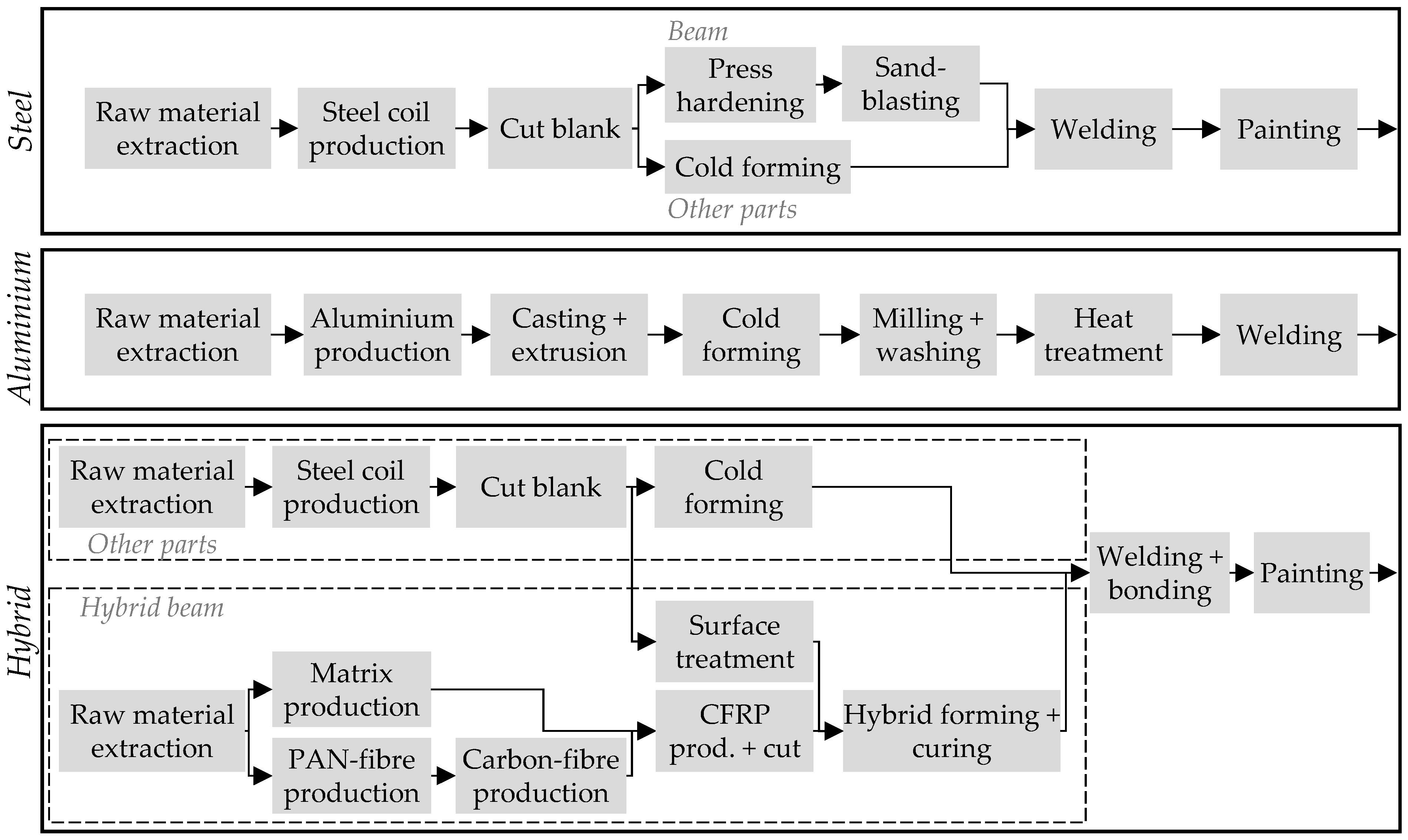
The scope of the case study is the life cycle of the CMS from raw material extraction through manufacturing and use until the end-of-life stage. As the manufacturing and processing technologies of the different material variants differ, the process routes of the production stage are also different, as shown in Figure 3.
For the steel variant, the raw material extraction is followed by the production of the steel coil, which is the input material for the component production. The steel can be produced via iron ore extraction and a blast furnace route or via a scrap-based electric arc furnace route. The steel coils are subsequently cut to the required size and formed. Apart from the beam, which is hot-formed for the steel variant, all other components are cold-formed. Finally, the individual parts are joined by welding and subjected to cathodic dip painting for corrosion protection. The parts of the aluminium variant are manufactured by extrusion, starting from bauxite mining and aluminium production. The extruded components are then formed, milled, subjected to heat treatment, and finally joined by welding. In the hybrid variant, apart from the beam, the components are manufactured according to the steel variant. Regarding the production of the hybrid beam, a distinction between the production of the steel and the CFRP layers is necessary. After the steel sheet has been cut, it is subjected to a surface treatment by means of laser structuring in order to improve the adhesion properties to the CFRP [57]. In the manufacturing process of the CFRP layers, the first step is the raw material production of epoxy resin and carbon fibres. For the carbon fibres, the most common manufacturing route based on polyacrylonitrile (PAN) [16] is considered. After polymerisation of PAN and spinning into PAN fibres, these are processed into C-fibres by stabilisation, carbonisation and a surface treatment. In particular, the heat treatment steps of stabilisation and carbonisation are associated with high energy demands and GHG emissions due to the high temperatures and long process times [16]. During stabilisation and especially carbonisation, chemical conversion processes lead to material degradation of the PAN precursor of 50% and more, which in turn releases various emissions, some of which have to be post-combusted and filtered [14]. The carbon fibre production is followed by the fibre fabric and CFRP prepreg production, in which the fabric is embedded in the matrix material. The steel blank and CFRP layers are subsequently stacked and formed into the final shape by a combined forming and curing process under the influence of pressure and temperature in a hydraulic press [57]. While the other CMS components are welded, the hybrid beam is joined by a bonding process. After joining, the hybrid CMS is coated by cathodic dip painting.
For the use stage of the CMS, installation in a BEV with a mileage (mile) of 200,000 km is assumed. The energy demand (ED) of the design alternatives is calculated based on Reimer et al. [3,58] as well as Eberle and Franze [58] by multiplying the CMS masses in kg ( m C M S ) and the ERV of 0.44 kWh/(100 km × 100 kg) [59] by the reciprocal of the charging efficiency ( η c h a r g e ) of 90%. The chosen ERV does not consider secondary mass effects and represents a midclass BEV and the Worldwide harmonised Light vehicles Test Procedure (WLTP) driving cycle.
E D = m C M S × E R V × m i l e η c h a r g e
For the end-of-life stage, a cut-off approach is chosen so that no credits are calculated for the recycling of materials. Since an equivalent shredding process with comparable GWP can be assumed for all three material variants, this process step is not considered in the study. Both the manufacturing and vehicle usage were assumed to take place in Europe. Based on the data basis described in detail in the next chapter, the GWP with a time horizon of 100 years (GWP100) is calculated in ecoinvent using the LCIA method of the International Panel on Climate Change (IPCC) from 2013 (assessment report 5). Herein, the abbreviation GWP always refers to GWP100.

4. Results

Using the method explained in Section 2, future scenarios for the identified key parameters are integrated into the LCE procedure of the three design alternatives of a CMS using pLCA. This chapter is thus divided into the three steps of the method, from conducting the initial LCA (I) to the implications for product development (III).

4.1. Initial LCA (I)

The goal of the initial LCA is to obtain the environmental impacts of the three CMS alternatives under current conditions. Current LCI data from the foreground and the background systems serve as a basis. The foreground data include, among others, information on energy and material requirements of production processes, while the background data include, among others, information on energy supply (e.g., energy sources, electricity mix) and material production. The scope of the study is defined according to the description in the previous section. For the LCI of the steel variant, datasets for hot-rolled, finished cold-rolled and hot-dip galvanised sheet steel from the World Steel Association [60] are used. For the calculation of the aluminium variant, data for aluminium ingots produced in Europe from European Aluminium [61] is used. The further steps of the process routes described in Figure 3 for the steel and the aluminium variant are calculated using primary industry data. The manufacturing process of PAN fibres is based on the information in Das [62] and a dataset in the GaBi database. For the further energy-intensive processing into C-fibres, generated LCI datasets are used on the basis of the specified material and the energy flows mentioned in Hohmann [14], Meng et al. [63], Das [62] and Arnold et al. [15]. The evaluation of the environmental impact of the epoxy resin matrix is based on the data provided in Bachmann et al. [64]. The GWP for the fibre fabric production is calculated using data from Stiller [65] and that for prepreg production and cutting using data from Suzuki and Takahashi [66], Witik et al. [67] and Nothdurft [68]. The laser structuring of the steel surfaces is based on laboratory measurements, which revealed an electrical energy demand of 6.1 MJ/m2. Laboratory measurements were also used to determine the energy demand of the combined forming and curing process used to produce the fibre-metal laminate beam for the hybrid design. In this case, an energy demand of about 1.8 MJ per component was determined. The joining processes and cathodic dip painting were determined using primary industry data. In the case of cathodic dip painting, the paint is neglected due to the unavailability of data. Since the energy demand is the main influencing parameter for climate change [69], it can be assumed that the resulting error by excluding this data for the painting process is negligible. For the energy supply in the form of electric power and thermal energy from natural gas datasets, the European average values from ecoinvent are used. For compressed air, the ecoinvent dataset for the global average is used.
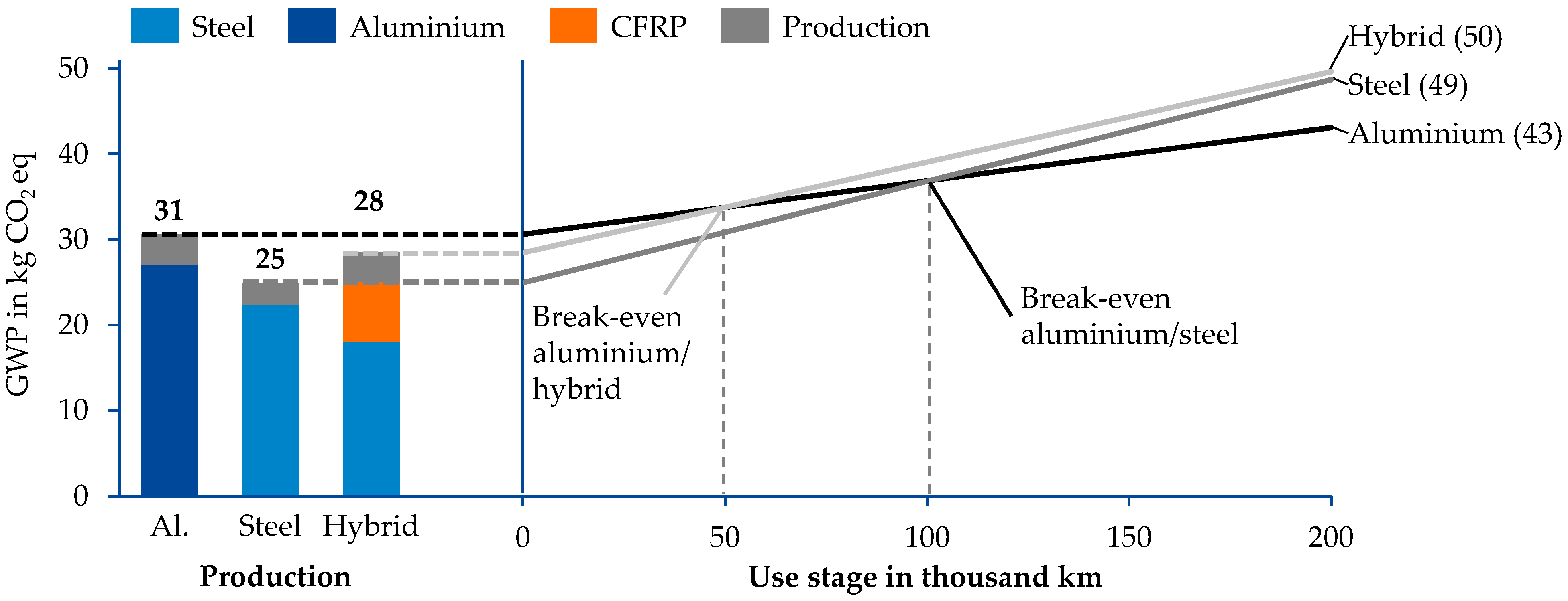
Figure 4 shows the results of the initial LCA for the three CMS design alternatives divided into the production stage (left) and the use stage of a BEV over a lifetime of 200,000 km (right). The production stage is divided into the production of the input materials (primary aluminium ingots, steel coils and CFRP) and the production of the final component (e.g., casting, forming, joining or coating). For the use stage, a linear increase in emissions is shown in order to highlight possible break-even points between the different designs. In this context, break-even points describe the distance after which higher emissions in the production phase can be offset by lower emissions in the use stage due to reduced component weight.
The results of the initial LCA show that, at current conditions, the steel variant has the lowest GWP in the production stage (25 kg CO2 eq.), followed by the hybrid (28 kg CO2 eq.) and the aluminium variant (31 kg CO2 eq.). Differences between the different designs in the production stage are mainly due to the higher emissions in the production of primary aluminium and CFRP compared to the steel reference. The component production itself has a smaller impact. The reduced masses of the aluminium and the hybrid design result in a lower energy demand and thus lower GWP in the use stage compared to the steel reference. Considering the manufacturing and use stage after 200,000 km, the lowest GWP value is 43 kg CO2 eq. for the aluminium variant, followed by 49 kg CO2 eq. for the steel and 50 kg CO2 eq. for the hybrid design. Against the background of the considered European electricity grid mix (0.32 kg CO2 eq./kWh [36]), the more GHG-intensive manufacturing of the aluminium design compared to the steel reference is thus equalised after about 101,000 km. A comparison of the hybrid design with the steel reference shows that the weight reduction in the hybrid design is not sufficient to offset the higher GHG emissions of the production within the considered use stage of 200,000 km. The break-even point between the aluminium and hybrid design is around 50,000 km.

Key Factor Analysis (I-a)

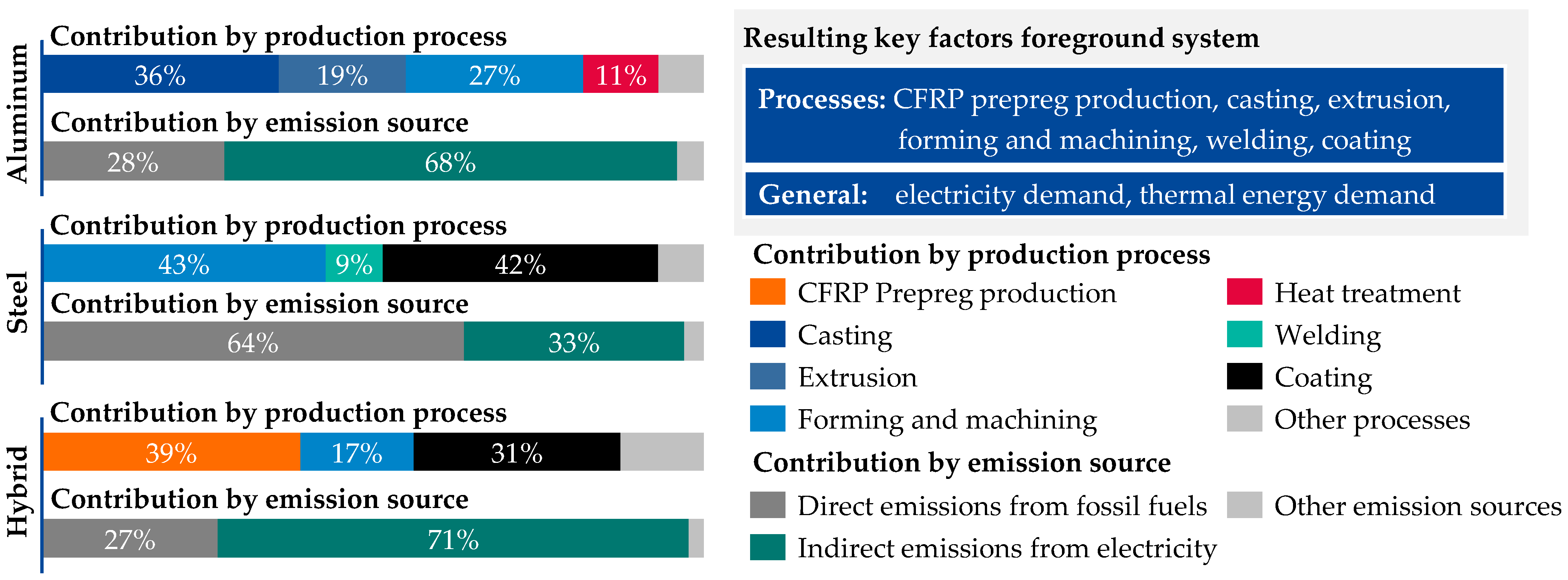
As part of the initial LCA, the key factors in the foreground and background systems are identified through a contribution analysis of the LCA results. A cradle-to-grave breakdown of the emissions in Figure 5 shows that for all three material variants, a significant proportion of the life cycle GWP is attributable to the production of the respective materials and the emissions from the use stage as part of the background system.
For the steel and aluminium variants, steel and aluminium production can thus be identified as key factors. In the case of the hybrid variant, the production of the epoxy resin as matrix material and that of the carbon fibre are added to the steel production as key factors. Since about 36% of the GWP of the carbon fibre production is due to the precursor production, this is also a key factor for the pLCA. The use stage also has a significant influence on the total GWP, with 28% (aluminium) to 49% (steel). Since BEVs do not directly emit GHG emissions, the GWP in the use stage correlates with the GHG emissions from electricity production. The electricity mix used and its GHG intensity is thus another key factor within the background system. For the background system, the GHG intensity of the energy supply and the material production are thus shown to be decisive factors for the decarbonisation of all material variants investigated.
A gate-to-gate breakdown of the emissions is shown in Figure 6 to display the relative contribution of influence factors in the foreground system. For each design alternative, the relative contribution of emissions to the foreground system is presented by a production process and emission sources. The breakdown by production process shows that casting, extrusion and forming are the main influencing factors for the aluminium variant (Figure 6). For the steel variant, more than 90% of the GWP is attributable to the forming, coating, and welding processes, which are thus identified as key factors. Within the forming process, the press hardening process of the beam is of particular importance. Regarding the hybrid variant, the prepreg production and cutting process is a major influencing factor in the foreground system. In addition, the combined forming and curing as well as the coating process can be identified as key factors. The breakdown by emission source shows that more than 95% of the GHG emissions for all three material variants can be attributed to direct emissions from heat-treatment processes and indirect emissions from the use of electricity. In addition to the key factor of the electricity grid mix in the background system, the electricity and thermal energy demands of the relevant process steps must therefore be considered in the following scenario development. The combined consideration of foreground and background systems reveals that, in addition to material production, the energy demand of individual production processes and GHG intensity of the energy supply in particular are essential leverages for reducing the life cycle GHG of the components.

4.2. Scenario Development (II)

Based on the identified key factors in the foreground and background systems, future projections are derived for each factor as part of the scenario generation. For the background key factors, available future scenarios for the background database, ecoinvent, and the literature research serve as the main sources of information. For the foreground key factors, the literature and discussions with process experts are used to generate the projections. The assumptions and associated references underlying the projections are described in Section 4.2.1 for all identified key factors. A tabular summary of these is provided in Appendix A, divided into the foreground (Table A1) and background (Table A2) systems.

4.2.1. Scenario Generation (II-a)

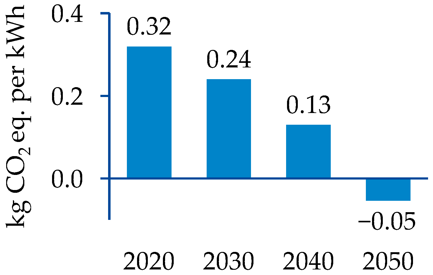
Electricity is one of the main energy forms used in the production processes and the only energy form in the use stage of this study. Therefore, the GHG intensity of the used electricity dataset has a significant influence on the results. Mendoza Beltran et al. [47] have introduced an approach to change background processes in the ecoinvent database [53] of LCA studies to perform pLCA studies by implementing scenarios of integrated assessment models (IAMs). Based on the work by Mendoza Beltran et al. [47], Sacchi et al. [70] have developed a Python-tool premise that allows the streamlined integration of different IAM scenarios into the LCI database, ecoinvent. By doing this, electricity markets are changed according to the selected scenarios. To consider future changes in the electricity grid mix of the production and use stages of the analysed CMS, the background system is changed using the premise according to the “SSP2-RCP 2.6” scenario from the integrated model to assess the global environment (IMAGE) for the years 2020, 2030, 2040 and 2050 [36]. The resulting emission intensity for the European electricity grid mix is shown in Figure 7. An important finding is that the scenarios may result in negative greenhouse gas emissions for electricity markets due to the application of carbon capture and storage (CCS) technologies to biomass electricity [70]. The adaptation of the ecoinvent database with premise is generally not limited to electricity markets. However, for material production such as aluminium, steel or CFRP, premise does not consider new technologies such as hydrogen-based steel production, that have a significant impact on the materials’ GHG emissions. Therefore, future projections for these factors are analysed separately.
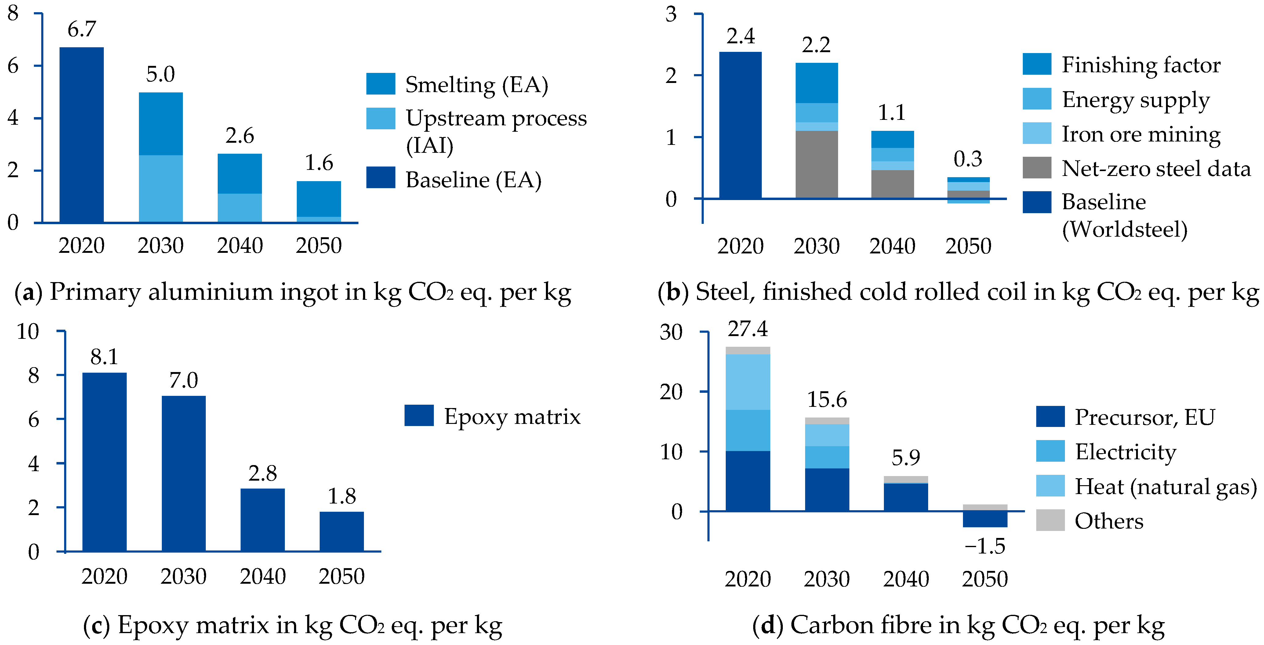
Since 1995, the GHG intensity of global steel production has remained at a constant level of around 2.5 kg CO2 eq./kg steel showing that efficiency improvements in the steel production are not sufficient to achieve a reasonable GHG intensity reduction [38]. However, in recent years, major steel-producing companies have published ambitious decarbonisation targets, developed roadmaps for the technical transformation of their steel-making facilities, and started investing in new technologies, such as steel-making based on green hydrogen via the direct reduction and electric arc furnace route (DRI-EAF) and carbon capture and utilisation technologies (CCU) [71]. Together with increased material efficiency and the increasing share of secondary steel in the global production, the introduction of CCU and hydrogen-based steel production can lead to significant emission reductions from the global steel sector as shown by the International Energy Agency (IEA) in their sustainable development scenario [37]. Although the IEA scenario provides a good overview of the possible reductions, it does not contain detailed data on future emissions from steel production at a regional level. The Net-Zero Steel (NZS) project has developed regionalised pathways with detailed available data for the introduction of low emission technologies worldwide to achieve a substantial decarbonisation of the global steel industry [38]. The NZS model on which the pathways are based assumes that existing production capacity will be replaced by different clean steel production technologies, depending on geographic feasibility and regional political situations. In their medium scenario, the authors project that by 2050, the production of scrap-based steel in EAF would reach 46% of global production [38]. Furthermore, 29% of all steel is produced with hydrogen-based DRI-EAF and 17% of the global production capacities use CCS [38]. The resulting emission factors for steel produced in Europe have been used in this study as a projection for the steel used in the CMS. However, the data only represent the production of crude steel and do not include any finishing processes such as rolling or coating. The mining of iron ores and indirect emissions from external energy are also not part of the data. Therefore, the NZS data were adapted as follows: The mining of iron ore was added as a constant value based on Wang et al. [72]. As the NZS project provides details on the consumption of coal, natural gas and electricity for each region and year, these consumption data were added to the LCA model and connected to the background system. The remaining gap between the most current World Steel data for hot- and cold-forming [60] was considered by further adding a constant “finishing factor”. The resulting emission factors for steel are exemplarily shown for finished cold-rolled steel in Figure 8.
The GHG emissions from the production of primary aluminium are significantly influenced by the energy supply and therefore vary significantly by the region of production and the local energy mix [13,74]. The average GWP of primary aluminium produced in Europe (6.7 kg CO2 eq./kg [61]) is 2.4 times lower than the global average (16.1 kg CO2 eq./kg [75]). This is mainly due to the high influence of the electricity mix used for the electrolysis process. In Europe, the GHG intensity of primary aluminium production has been reduced by 55% from 1990 until 2015 [39]. Further advances are possible through technologies that are currently under development, such as the usage of inert anodes that reduce direct emissions from the electrolysis process [76]. Possible future pathways for the decarbonisation of the primary aluminium production have been analysed by the International Aluminium Institute (IAI) and the European Aluminium Association (EA) [39,40]. The main measures to reduce GHG emissions analysed in these publications are the decarbonisation of the electricity used in the process and the introduction of new technologies, such as the electrolysis with inert anodes that reduces direct emissions from electrolysis, or the usage of carbon capture and usage or storage (CCUS) technologies [39,40]. For the future projections of the key factor primary aluminium production, the most optimistic EA scenario was used due to the best regional consistency with the study. The EA scenario considers a decrease in indirect emissions from electricity supply and the introduction of technologies that reduce direct emissions from the smelting process as a basis. The scenario assumes that 23% of the European production of primary aluminium will avoid direct GHG emissions through inert anodes or CCUS [39]. Since the EA scenario does not consider any changes in the bauxite mining and alumina production, global IAI data from the IAI 1.5 °C scenario for these life cycle stages have been used in this study [75]. The latest available values from EA were used as a starting value for base year 2020. The resulting emission factors for primary aluminium ingot are shown in Figure 8.
The GWP of the matrix material production for CFRP depends first of all on the polymer material used and its characteristics [17], whereby this work is limited to epoxy resins. For epoxy matrix materials, which are composed of the resin and a curing agent, the GWP values given in the literature vary significantly. In Deng’s work [18], a value between 4.7 and 8.1 kg CO2 eq./kg epoxy is mentioned, whereas in the study by Hohmann [43], a value between 6 and 14 kg CO2 eq./kg epoxy is given. As a baseline value for 2020, a value of 8.1 is assumed in this study, which is based on the industrial data from Plastics Europe [64]. According to Hohmann [73], there is potential for reducing the GWP of the epoxy matrix by using renewable energy sources for thermal and electrical energy as well as power-to-x technologies (PtX) in the production process. In addition, GHG emissions can be reduced by using biobased raw materials. Combining both approaches results in a reduction potential of about 78% compared to the baseline value of the petroleum-based epoxy resin [73]. In the scenario considered for epoxy matrix in this paper, it is assumed that this potential will be fully exploited by 2050. Since the necessary infrastructure must still be built and the technologies used are not yet ready for the market, it is assumed that this potential will not be increasingly exploited until 2030.
In contrast to steel and aluminium, for which LCI data are partly broken down by individual process steps and provided by associations such as World Steel, the availability of data for carbon fibre production is limited [16]. Since aggregated GWP values, if any, are provided in the literature, an investigation of the contributions of individual process steps, as well as the generation of future scenarios, is associated with higher uncertainties. According to Hohmann [43], who refers to various studies such as those by Moretti [77], Arnold [42] and Reno [78], there is potential for reducing GHG emissions in PAN precursor production through the biobased production of the acrylonitrile (ACN) monomer, which is conventionally made from petroleum and contributes to about 80% of the emissions in PAN precursor production. By using production routes via bio-naphtha, bio-methanol and e-methanol, it is possible to reduce the GWP of ACN by more than 30% [43]. If green energy sources for thermal and electrical energy as well as PtX technologies are used in these manufacturing routes, the climate impact per kilogram ACN can be reduced by 75 to 80% compared to the conventional petroleum-based ACN [43]. In the best case scenario, the additional use of CCU technologies in the production route via e-methanol makes it possible to produce ACN and carbon fibres with negative GWP [73]. In this study, it is assumed that this potential can be fully exploited by 2050 and that 100% of the used precursor will be produced with negative GWP in 2050. Between 2020 and 2050, it is assumed that there will be a gradual transition from 100% petroleum-based production with current energy supply to the bio-naphtha, bio-methanol, and e-methanol routes, with increasingly green energy supply. In addition to the optimisation of PAN precursor production, the use of an alternative, for example, biobased precursor materials such as lignin, also offers the possibility of reducing emissions [41]. However, these are not considered in this study.
The further processing of the precursor into carbon fibres is currently associated with high GHG emissions due to the high energy demands in the order of 32 MJ [14] to 125 MJ [15] of electrical and 98 MJ [62] to 178 MJ [63] of thermal energy per kilogram carbon fibre. In addition, there are influences from necessary consumables, such as electrolytes for coating and nitrogen for carbonisation [14], so that future scenarios must also be considered for these process steps. Current GWP data for carbon fibres in the literature often assume region-specific average values for the GHG intensity of the electricity mix and the use of natural gas for heat [14], e.g., for Europe, as is the case for 2020 in this study. In the future, the GWP could be reduced by switching to renewable energy sources such as biogas for thermal and hydropower for electricity [43]. Additional GHG-savings potentials are possible through the electrification of thermal energy supply, energy efficiency measures and the use of more energy-efficient-processing technologies, e.g., for heating [73]. For example, Hermansson et al. [41] investigate the electricity-based conversion of precursor to carbon fibre on the basis of microwave heating, indicating an energy saving potential of more than 90%. In this study, an average reduction in energy demand of 50% for the process steps stabilisation, carbonisation and surface treatment is assumed by 2050. In addition, a complete electrification of the processes and the use of electricity from 100% renewable energies by 2040 is supposed. Compared to the baseline value in 2020, precursor utilisation in the carbon fibre production is expected to increase from 50% to 60% by 2050, based on Dér [16]. Together with the described scenario for precursor production, this results in the projection of carbon fibre production up to the year 2050 shown in Figure 8.
The main impact within the foreground production processes for aluminium and steel manufacturing, including blanking, cold-forming, extrusion, welding, heat treatment and sandblasting, results from the demand of electrical energy. These processes have been established in the automotive industry for many years. For the future projection of these processes, it was therefore assumed that no radical changes or innovations will take place. However, an annual decrease in energy consumption by 1% through energy efficiency measures is assumed. For the aluminium ingot-casting process, the hot-forming process and the coating process, natural gas serves as the main energy source for heating. To assess future potentials for these processes, a full electrification of all three processes by 2030 is assumed.
In the context of aluminium ingot remelting and subsequent casting, heating processes utilising natural gas are conventionally employed [61]. However, aluminium melting with electrical energy is also possible, for example, with electric resistance furnaces [11]. A comparable transition could be made for hot-forming processes, for which natural-gas-fired roller hearth furnaces are typically used for heating the blanks [35]. Electrical or hybrid heating of roller hearth furnaces is also possible [35]. Furthermore, alternative heating technologies such as inductive heating are currently developed [34]. Concepts for the electrification of relevant coating process steps are also under development [79]. As the amount of electricity needed to substitute natural gas during the heating process depends on the technology employed, and detailed information is currently unavailable, it is assumed that one MJ of natural gas is substituted by one MJ of electricity for each technology. Given that electrical heating can lead to higher efficiencies compared to natural gas usage [80], this can be regarded as a conservative approach.
Besides energy consumption, the material efficiency of the production processes has a major impact on the GWP of the product. The sustainable development scenario of IEA expects that the total consumption of steel can be reduced by around 13% due to increased yields in manufacturing processes [37]. Therefore, a linear reduction in the required amount of steel by 13% is considered for the steel and the hybrid design until 2050. For the aluminium design, a linear increase in the material yield by 10% for the extrusion process is assumed until 2050. However, the effect is comparably low since the material from extrusion is nevertheless directly reused for the casting process.
Similar to the foreground processes of aluminium and steel processing, the climate impact of the further processes for CFRP and FML-hybrid manufacturing result from indirect emissions due to electrical energy demands. Stiller [65] as well as Suzuki and Takahashi [66] published energy demand data of the fibre fabric and thermoset prepreg production. The energy demand values given therein for carbon fibre fabric production (0.19 MJ/m2) and prepreg production (40 MJ/kg prepreg) serve as a baseline for 2020 in this study. Since approximately 90% of the energy demand is attributable to the storage and climatization of the prepreg materials, it can be assumed that the energy demand can be reduced by optimised logistics processes, resulting in reduced storage times. In this study, a linear reduction in energy demand of 50% is assumed by 2050. The same applies to the two-dimensional cutting of the prepreg, the basic energy requirement of which is based on an average value of the data provided by Witik et al. [67] and Nothdurft [68].
The climate impact of the combined forming and curing process is entirely due to indirect emissions from electricity. The electrical energy demand is generated by the temperature control of the forming die and by the hydraulic press, which were measured in laboratory tests. A significant influence for the electrical energy demand arises from the fact that the hydraulic press runs under load for the entire curing time of the component in the mould (8 min for the prepreg material used). This can be considered a worst-case scenario, since there are press concepts where the energy demand in this operating phase can be reduced by a suitable control. The use of faster curing matrix systems would therefore reduce the energy demand. In addition, energy-saving measures by using more energy-efficient presses and mould heaters are conceivable. In the scenario considered for the combined forming and curing process, it is assumed that the curing time of the prepreg can be reduced to three minutes [81] and the energy demand can be reduced by a further 50% through additional energy efficiency measures. Moreover, based on the data provided by Hohmann [14], an increase in material efficiency from 92% to 96% is assumed through the optimisation of the manufacturing processes.

4.2.2. Scenario Evaluation (II-b)

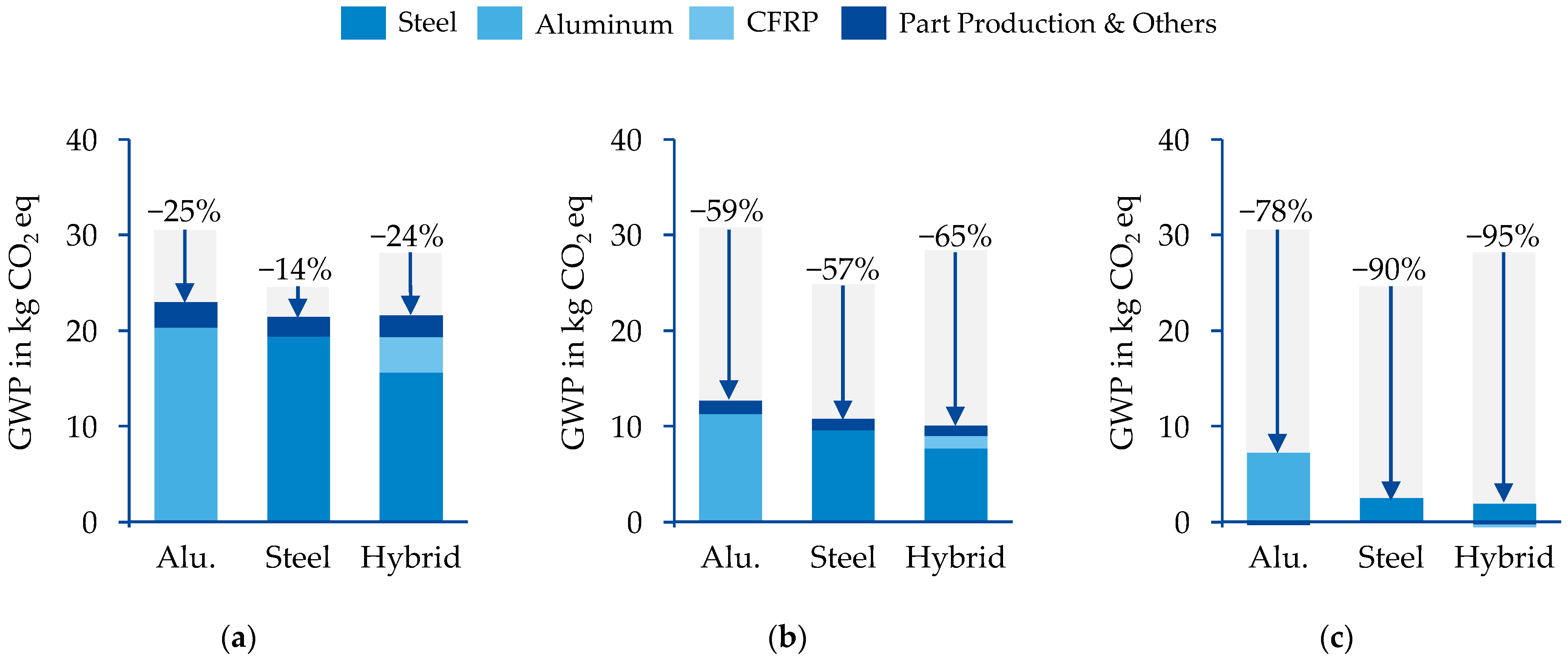
For the scenario evaluation, the projections described above were implemented in the LCA model for all three CMS design variants. The results were analysed for the years 2030, 2040 and 2050 in comparison to the baseline year 2020. Figure 9 shows the results for the life cycle stages material production and component production (cradle-to-gate perspective). For each year of consideration, the emissions are broken down by the material production and part production. The figure also shows the relative GWP reduction achieved compared to the reference year 2020.
Compared to 2020, a 25% and 24% reduction in GWP is achievable for the aluminium and hybrid designs in 2030, respectively. For the steel design, a GWP reduction of 14% is possible. Both the improvements in material production and the changes in the production processes contribute to this decrease. Material production accounts for 84 to 87% of absolute reductions, depending on the design variant. This trend continues for the years 2040 and 2050. By 2050, under the assumed future projections, GWP reductions of 78% for the aluminium, 90% for the steel and 95% for the hybrid variant are possible. These potentials result in the highest GHG emissions for the production of the aluminium variant and the lowest for the production of the hybrid variant in 2050. Under these conditions, the GWP from the production processes are close to zero and may even result in negative GHG emissions due to negative emissions from electricity generation.
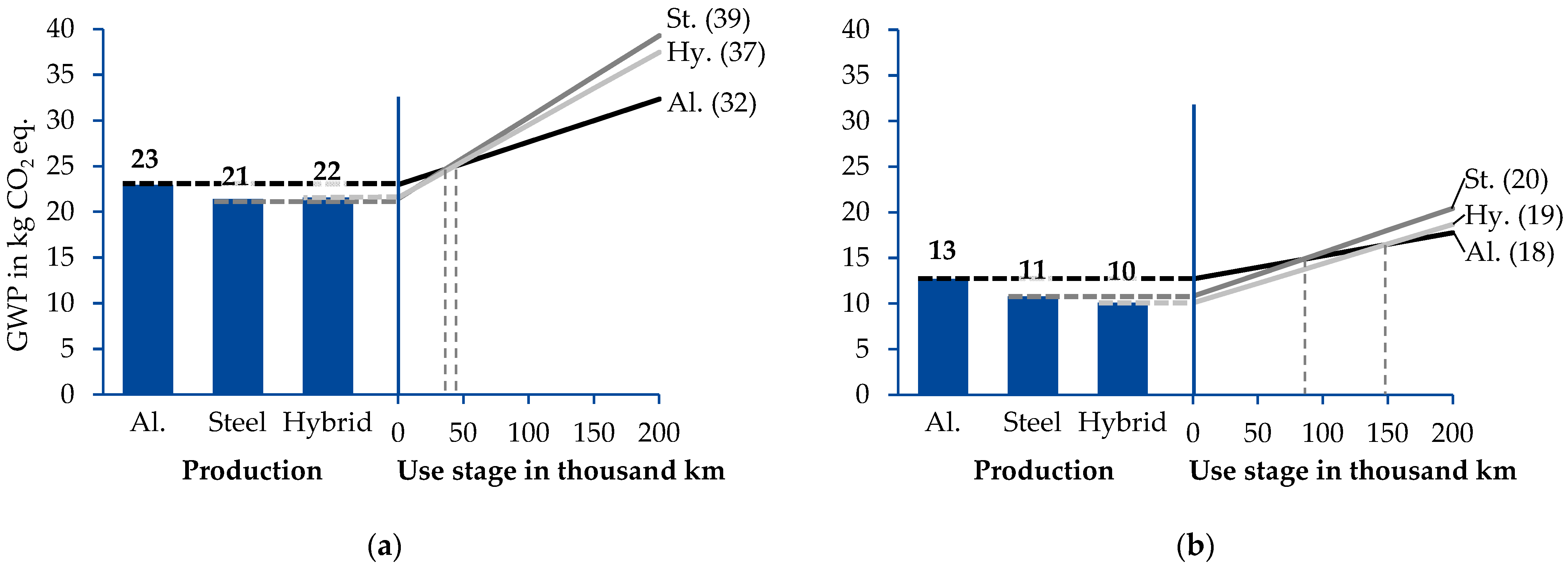
For the years 2030 and 2040, the use-stage emissions must be considered to allow decision making between the different design alternatives. Figure 10 shows the results of the prospective LCA for the three CMS design alternatives, divided into the production stage (left) and the use stage of a BEV over a lifetime of 200,000 km (right). For the use stage, a linear increase in emissions in the use stage is shown in order to highlight possible break-even points between the different designs. The electricity mix is assumed to be constant over the use stage according to the mentioned electricity scenario (Figure 7). For 2030, the slightly higher emissions from the production of the aluminium design are compensated over a lifetime and lead to the lowest emissions after 200,000 km of use compared to the steel and hybrid designs. The break-even point between the aluminium and the steel designs is after 36,000 km and between the aluminium and the hybrid designs is after 42,000 km. The production and use of the hybrid design emits slightly lower GHGs compared to the steel design. Considering the production and use stage, the lowest GWP value is 32 kg CO2 eq. for the aluminium variant, followed by 37 kg CO2 eq. for the hybrid and 39 kg CO2 eq. for the steel design. For 2040, the higher GWP from the aluminium variant production can still be compensated over a lifetime compared to the steel design (break-even at 83,000 km) and the hybrid design (break-even at 147,000 km). Considering the production and use stages, the lowest GWP value is 18 kg CO2 eq. for the aluminium variant, followed by 19 kg CO2 eq. for the hybrid and 20 kg CO2 eq. for the steel design. However, the results are very close to each other, which makes a clear decision difficult. To test the robustness of the decision, we have performed a sensitivity analysis for the year 2040 by changing the ERV as one decisive parameter for the effect of lightweight design in the use phase. Varying the ERV by +20% and −20% shows a shift of the break-even points. For example, the break-even point between steel and aluminium is 25 km later when a 20% lower ERV is applied. However, the advantageousness of the aluminium design over the entire life cycle remains unchanged. Only a 26% lower ERV leads to a change in the decision from aluminium design to hybrid design. For the year 2050, when emissions from the electricity grid mix are negative according to the described scenario, accounting for the use stage leads to negative emissions and thus not meaningful results, since a higher energy demand is associated with lower GHG emissions. Assuming that the GHG emissions of electricity generation and, subsequently, the GWP of the use phase are zero in 2050, the most favourable design can then be determined solely based on the emissions from the production stage (compare Figure 9c). With 1.5 kg CO2 eq., the hybrid variant has the lowest emissions, followed by 2.5 kg CO2 eq. for the steel variant and 7 kg CO2 eq. for the aluminium design. This result shows that a shift in the climate-optimal design is possible by 2050 and the hybrid design can become the one with the lowest GWP under the considered scenario.

4.3. Implications for Product Development (III)

In the analysed CMS case study, the aluminium design shows the lowest life cycle GHG emissions in 2020 and 2030 due to the high weight reduction compared to the other designs and the resulting reduced GHG emissions in the use stage. However, from 2040 onwards, the hybrid design is nearly comparable to the aluminium design in terms of life cycle GWP and would lead to significantly reduced emissions until 2050, as the GWP of the production stage of the hybrid design can be reduced further between 2040 and 2050. For near-term design decisions, the aluminium design is therefore favourable. From the current perspective and under the shown projections, a change towards a steel-CFRP hybrid design of the considered CMS would be favourable after 2040. An increase in the proportion of the hybrid material in the CMS could also offer the potential to further reduce the GWP of the hybrid variant from 2040 onwards. It is also shown that, despite an increased GWP in the production stage, the use of lightweight materials can lead to lower climate-change impacts over the life cycle even for electricity mixes with very low GHG intensity in the use stage. The prerequisite for this is the implementation of suitable measures to reduce the GWP in the production stage, such as the use of sustainably produced raw materials, efficient production processes, and renewable energy sources in accordance with the scenarios developed.

5. Conclusions and Discussion

This paper provides the methodological foundation for the integration of pLCA in the development process for automotive components. Previous approaches to pLCA of lightweight structures, such as those of Hermansson et al. [41], Dér et al. [44], Morimoto et al. [51] and Koroma et al. [52], are extended by taking into account not only individual and partly subjectively selected influencing parameters, but all parameters which are systematically identified as relevant. For this purpose, a systematic procedure is provided. The methodological foundation can support LCA practitioners in conducting pLCA studies of lightweight structures and enables improved decision-making in product development. Including a prospective view on the environmental impacts of different design alternatives increases the confidence in essential decisions in product and strategy development. The case study of a lightweight structure demonstrates the practical applicability of the methodological foundation. It provides a direction for future developments of vehicle lightweight components and their influencing parameters.
The analysed case study shows significant potentials to reduce the GWP of all three component design variants which is consistent with pLCA results on a full vehicle level as shown by Morimoto et al. [51] and Koroma et al. [52], as well as on component level as shown by Hermansson et al. [41]. The identification of key factors and the development of their future projections have revealed the importance of energy demand as well as energy and material supply over the entire life cycle for reducing the GWP of the products under study. In line with other publications, our results show the particular importance of the decarbonisation of background factors such as the electricity grid mix [47,51,52] and the material production [41,51,52] for the decarbonisation of the whole product system. In line with Dér et al. [44], the decarbonisation of the foreground system factors results in a lower potential for reducing the life cycle GHG emissions of the lightweight product. In terms of decision-making, it was shown that the proposed aluminium design is favourable even if it is produced until 2030 and used until 2040. The example has also shown that hybrid steel–CFRP parts can lead to reduced GHG emissions in future cars, and further developments in this field are therefore reasonable if ecological aspects are taken into account. These findings are, of course, specific for the analysed case study and can differ from findings for other components, designs and system boundaries. We have shown that deviations in the ERV can significantly influence the result of the study. To increase the confidence of the results, a consistent sensitivity analysis of all parameters would be of additional value for the methodology and should be part of future research. Furthermore, other parameters such as the length of the use stage or the type of operation can significantly change the results as shown by Dér et al. [44]. Further research should also focus on broadening the results by implementing further elements such as the end-of-life stage or the usage of secondary materials in the considered scenarios. Other calculation approaches for the end-of-life stage, which, for example, also take into account the recyclability of materials, could change the result especially for the hybrid variant [82]. The influence of using secondary materials as presented by Morimoto et al. [51] and other circular economy approaches could also be investigated to show further decarbonisation potentials.
In addition to being used in decision-making, the pLCA results provide search fields for further innovations and developments. This is due to the fact that the shown projections only provide theoretical potentials for GHG emission reduction. The technologies that make these reductions possible are however still under development. The electrification of the hot-forming process, for example, has not yet been widely used in Europe as heating with natural gas is more cost efficient [83]. Thus, the development of technologies that allow an attractive electrification of hot-forming processes from an economic perspective is needed. For the coating process, the technical realisation of a full electrification has also not been realised until now and must be developed to lift the shown potentials. Regarding the scenarios considered for CFRP production, it must be especially taken into account that these are still in the development phase, so that it cannot be assumed with certainty that the potential described can be exploited at all, and especially not in the short term. Since the data basis is very limited, it should be noted that both the baseline values and the future scenarios are associated with a high degree of uncertainty. This applies in particular to the biobased production of the precursor material [73]. Nearly all the projections described also assume that the necessary infrastructural measures are taken to have sufficient renewable energy available. This assumption regarding energy systems is also associated with a high degree of uncertainty, as the future development of these depends on numerous factors and can vary considerably across regions.
One general limitation to consider is that even if GHG emissions are becoming an additional design criterion, decisions in the automotive industry are often predominantly made based on costs [84]. High material and additional processing efforts can result in significantly higher costs for aluminium and even more for hybrid designs compared to steel, especially in the case of large production volumes [85]. To address this, the development of processes with reduced cycle times, as discussed in the projections for the forming and curing of the hybrid beam, is a potential measure to reduce additional costs and should be further developed. Even though GWP is currently the most prominent impact category in the automotive practice, further impact categories, such as resource depletion or water consumption, may become increasingly important for decision-making in the future.
Although this paper provides the methodological foundationfor integrating pLCA into the LCE procedure, there is a need for future expansion both in terms of the scenarios considered and the methodology developed. Thus, until now, only best-case scenarios of the parameters identified as relevant are considered. Less optimistic, but quite realistic scenarios are excluded. However, as proposed by Arvidsson et al. [32], several extreme scenarios or scenario ranges should be considered when the future is difficult to predict. If further projections are also taken into account for all parameters, this results in a significantly larger space of projections and possible combinations, which are not always consistent with each other [86]. To deal with this increased complexity, an extension of the presented methodology is needed, which allows a more comprehensive evaluation of dependencies and interactions between the parameter projections to obtain consistent scenarios for the pLCA.

Author Contributions

Conceptualisation, methodology, investigation and case study, visualisation, writing—original draft preparation, M.O. and J.G.; case study, M.T.; methodology, writing—review and editing, F.C. and T.M.; supervision, funding acquisition, writing—review and editing, T.T.; supervision, writing—review and editing, C.H. All authors have read and agreed to the published version of the manuscript.

Funding

This research was funded by the Ministry of Economic Affairs, Innovation, Digitalisation and Energy of the State of North Rhine-Westphalia (MWIDE NRW), Germany, within the project Climate Neutral Business in Ostwestfalen-Lippe (Climate bOWL), grant number 005-2111-0020.

Data Availability Statement

Data are contained within the article.

Acknowledgments

The authors acknowledge the support of BENTELER Automobiltechnik GmbH.

Conflicts of Interest

The authors declare no conflict of interest.

Appendix A

Table A1. Assumptions for the scenario development of the foreground system.
Key FactorAssumptions
Hot-forming
process
  • Heating processes are electrified from 2020, reaching 100% electrification by 2030 (linear substitution of natural gas consumption by electricity; 1 kWh of natural gas is compensated by 1 kWh of electricity)
  • Through continuous improvements, the energy consumption of all forms of energy is reduced linearly with a 1% reduction per year as a conservative assumption
Coating
(cathodic
dip coating)
  • Assumptions identical to those of the key factor “Hot-forming process”
Aluminium Casting and
Extrusion
  • Assumptions identical to those of the key factor “Hot-forming process”
Other processes: Welding, Surface Treatment, Forming and Machining
  • Through continuous improvements, the electrical energy consumption is reduced linearly with a 1% reduction per year as a conservative assumption
Hybrid
forming and curing
process
  • Based on industry specification data for fast-curing prepregs [81], the energy consumption can be reduced by using a fast-curing matrix material. This technology change enables the curing time to be reduced to three minutes from 2030 onwards
  • In addition, from 2020, a linear reduction in the electrical energy demand by 50% until 2050 is assumed. Based on expert evaluations, this can be achieved by using more efficient press technologies and mould-heating methods
Prepreg production and cutting
  • From 2020, storage, climate control, production and processing steps of thermoset CFRP prepregs can be optimised, so that the energy demand can be reduced by 50% until 2050 (linear reduction). The value is based on the assumption of process experts
Material efficiency in
Production
processes
  • Material efficiency is increased according to theoretical potentials from the literature. The amount is reduced linearly starting in 2020 and reaching the full theoretical potential in 2050
  • Steel: Based on the sustainable development scenario of IEA, the total consumption of steel can be reduced by around 13% due to increased yields in manufacturing processes [37]
  • Aluminium: Based on data from the Global Aluminium Cycle 2021 [87], the material yield of the aluminium extrusion production can be improved by 10%
  • CFRP Prepreg: Based on data from Hohmann [14], offcuts can be reduced from 8% to 4%
  • Based on Hohmann [14] and Dér et al. [16], the material yield for the conversion of PAN precursor to carbon fibre can be increased from 50% to 60%
Table A2. Assumptions for the scenario development of the background system.
Key FactorAssumptions
Electricity generation
  • The data for electricity generation are based on the SSP2 “Middle-of-the-Road” socio-economic pathway with a prospective scenario that complies with the climate change mitigation target RCP 2.6 corresponding to a global atmospheric temperature increase by 2100 with respect to pre-industrial levels of below 2 °C
  • According to this scenario, the GWP of electricity generation in Europe is reduced significantly between 2020 and 2050 through the expansion of renewable energy generation and the introduction of carbon capture technologies
Steel production
  • Based on the Net-Zero Steel Project (NZS) scenario [38], the GWP of steel coil production is reduced significantly between 2020 and 2050, reaching a reduction of 89% until 2050
  • The scenario introduces decarbonisation pathways by implementing higher shares of secondary steel production, hydrogen-based DRI-EAF and CCUS technologies
  • Upstream emissions for ore mining are considered by adding a constant value based on historical data shown in Wang et al. [72]
  • Downstream emissions from finishing processes (e.g., rolling) are considered by adding a constant finishing factor based on World Steel data [60]
  • Emissions from energy supply are calculated separately with data from the background database, ecoinvent. Energy consumption is based on the given NZS Scenario
Primary aluminium production
  • Based on the European Aluminium (EA) Vision 2050 scenario [39], the GWP of primary aluminium production is reduced significantly between 2020 and 2050. The reductions are caused through the decarbonisation of the power sector and the introduction of smelting technologies that reduce direct emissions
  • Until 2050, 23% of the primary aluminium production will avoid direct emissions through the introduction of carbon capture and inert anode technologies
  • The EA scenario only considers emissions from the aluminium-smelting process. Thus, further upstream emissions from mining, refining and anode production are calculated based on the 1.5 degrees aligned scenario from IAI [40]
Epoxy matrix production
  • Based on data provided by Hohmann [73], the combined use of renewable energy sources, PtX technologies and biobased raw materials in epoxy production can lead to a reduction in the GWP per kilogram epoxy matrix by 78%
  • This potential can be fully exploited by 2050, with the technologies being integrated mainly between 2030 and 2040
PAN precursor production
  • Based on data provided by Hohmann [43,73], the combined use of renewable energy sources, PtX and CCU technologies as well as biobased ACN in the precursor production route can lead to a negative GWP per kg PAN precursor
  • Assuming a gradual transition process, this potential can be fully exploited by 2050
Carbon fibre production
  • Based on the inventory data provided by Hohmann [14], Dér et al. [16], Das [62] and Arnold et al. [15], the GWP for the conversion process from PAN fibres to carbon fibres can be significantly reduced through the electrification of heating processes, use of renewable energy sources and energy efficiency measures
  • Heating processes are electrified from 2020, reaching 100% electrification by 2040 (linear substitution of natural gas consumption by electricity; 1 kWh of natural gas is compensated by 1 kWh of electricity)
  • By 2040, a 100% transition to renewable energy sources is expected to be achieved
  • Through efficiency measures and technological innovations, the total energy demand can be reduced by 50% until 2050. This value is based on energy efficiency potentials provided by Hermansson et al. [41]

References

  1. Regulation (EU) 2021/1119 of the European Parliament and of the Council of 30 June 2021 Establishing the Framework for Achieving Climate Neutrality and Amending Regulations (EC) No 401/2009 and (EU) 2018/1999 (‘European Climate Law’): (EU) 2021/1119. 2021. Available online: https://eur-lex.europa.eu/legal-content/EN/TXT/?uri=CELEX%3A32021R1119 (accessed on 5 March 2023).
  2. European Environmental Agency. EEA Greenhouse Gases: Sectoral Shares in EU-27 in 2020. Available online: https://www.eea.europa.eu/data-and-maps/data/data-viewers/greenhouse-gases-viewer (accessed on 9 August 2022).
  3. Reimer, L.; Kaluza, A.; Cerdas, F.; Meschke, J.; Vietor, T.; Herrmann, C. Design of Eco-Efficient Body Parts for Electric Vehicles Considering Life Cycle Environmental Information. Sustainability 2020, 12, 5838. [Google Scholar] [CrossRef]
  4. Koffler, C.; Rohde-Brandenburger, K. On the calculation of fuel savings through lightweight design in automotive life cycle assessments. Int. J. Life Cycle Assess. 2010, 15, 128–135. [Google Scholar] [CrossRef]
  5. Egede, P. Environmental Assessment of Lightweight Electric Vehicles, 1st ed.; Springer International Publishing: Cham, Switzerland, 2017; ISBN 9783319402772. [Google Scholar]
  6. Delogu, M.; Del Pero, F.; Pierini, M. Lightweight Design Solutions in the Automotive Field: Environmental Modelling Based on Fuel Reduction Value Applied to Diesel Turbocharged Vehicles. Sustainability 2016, 8, 1167. [Google Scholar] [CrossRef] [Green Version]
  7. Del Pero, F.; Berzi, L.; Antonacci, A.; Delogu, M. Automotive Lightweight Design: Simulation Modeling of Mass-Related Consumption for Electric Vehicles. Machines 2020, 8, 51. [Google Scholar] [CrossRef]
  8. Luk, J.M.; Kim, H.C.; de Kleine, R.; Wallington, T.J.; MacLean, H.L. Review of the Fuel Saving, Life Cycle GHG Emission, and Ownership Cost Impacts of Lightweighting Vehicles with Different Powertrains. Environ. Sci. Technol. 2017, 51, 8215–8228. [Google Scholar] [CrossRef] [PubMed]
  9. Muttana, S.B.; Sardar, A. Lightweighting of Battery Electric Cars: An Impact Analysis Using Indian Driving Cycle. In SAE Technical Paper Series, Proceedings of the 8th SAEINDIA International Mobility Conference & Exposition and Commercial Vehicle Engineering Congress 2013 (SIMCOMVEC), Chennai, India, 4 December 2013; SAE: Warrendale, PA, USA, 2013. [Google Scholar]
  10. Wang, J.; Li, Y.; Hu, G.; Yang, M. Lightweight Research in Engineering: A Review. Appl. Sci. 2019, 9, 5322. [Google Scholar] [CrossRef] [Green Version]
  11. Herrmann, C.; Dewulf, W.; Hauschild, M.; Kaluza, A.; Kara, S.; Skerlos, S. Life cycle engineering of lightweight structures. CIRP Ann. 2018, 67, 651–672. [Google Scholar] [CrossRef]
  12. Haraldsson, J.; Johansson, M.T. Effects on primary energy use, greenhouse gas emissions and related costs from improving energy end-use efficiency in the electrolysis in primary aluminium production. Energy Effic. 2020, 13, 1299–1314. [Google Scholar] [CrossRef]
  13. Nunez, P.; Jones, S. Cradle to gate: Life cycle impact of primary aluminium production. Int. J. Life Cycle Assess. 2016, 21, 1594–1604. [Google Scholar] [CrossRef] [Green Version]
  14. Hohmann, A. Ökobilanzielle Untersuchung von Herstellungsverfahren für CFK-Strukturen zur Identifikation von Optimierungspotentialen: Systematische Methodik zur Abschätzung der Umweltwirkungen von Fertigungsprozessketten. Ph.D. Dissertation, Technische Universität München, München, German, 2019. [Google Scholar]
  15. Arnold, U.; de Palmenaer, A.; Brück, T.; Kuse, K. Energy-Efficient Carbon Fiber Production with Concentrated Solar Power: Process Design and Techno-economic Analysis. Ind. Eng. Chem. Res. 2018, 57, 7934–7945. [Google Scholar] [CrossRef]
  16. Dér, A.; Dilger, N.; Kaluza, A.; Creighton, C.; Kara, S.; Varley, R.; Herrmann, C.; Thiede, S. Modelling and analysis of the energy intensity in polyacrylonitrile (PAN) precursor and carbon fibre manufacturing. J. Clean. Prod. 2021, 303, 127105. [Google Scholar] [CrossRef]
  17. Hill, C.; Norton, A. LCA Database of Environmental Impacts to Inform Material Selection Process, DACOMAT. 2018. Available online: https://www.sintef.no/globalassets/project/dacomat/dacomat-deliverable-6.1.pdf (accessed on 5 March 2023).
  18. Deng, Y. Life Cycle Assessment of Biobased Fibre-Reinforced Polymer Composites. Ph. D. Dissertation, KU Leuven, Leuven, Belgium, 2014. [Google Scholar]
  19. Jacob-Lopes, E. Sustainability Metrics and Indicators of Environmental Impact: Industrial and Agricultural Life Cycle Assessment; Elsevier: Amsterdam, The Netherlands, 2021. [Google Scholar]
  20. ISO 14040:2006; Environmental Management—Life Cycle Assessment—Principles and Framework. International Standardization Organization: Geneva, Switzerland, 2006.
  21. Hauschild, M.Z.; Herrmann, C.; Kara, S. An Integrated Framework for Life Cycle Engineering. Procedia CIRP 2017, 61, 2–9. [Google Scholar] [CrossRef] [Green Version]
  22. Reimer, L.; Jois, P.K.; Henkelmann, H.; Meschke, J.; Vietor, T.; Herrmann, C. Systematic Design of Body Concepts Regarding Mini-Mal Environmental Impacts in an Early Concept Phase. In Technologies for Economic and Functional Lightweight Design; Dröder, K., Vietor, T., Eds.; Springer Vieweg: Berlin/Heidelberg, Germany, 2021; pp. 97–109. ISBN 978-3-662-62924-6. [Google Scholar]
  23. Kaluza, A.; Kleemann, S.; Fröhlich, T.; Herrmann, C.; Vietor, T. Concurrent Design & Life Cycle Engineering in Automotive Lightweight Component Development. Procedia CIRP 2017, 66, 16–21. [Google Scholar] [CrossRef]
  24. Hirz, M.; Nguyen, T.T. Life-Cycle CO2-Equivalent Emissions of Cars Driven by Conventional and Electric Propulsion Systems. World Electr. Veh. J. 2022, 13, 61. [Google Scholar] [CrossRef]
  25. Koffler, C. Life cycle assessment of automotive lightweighting through polymers under US boundary conditions. Int. J. Life Cycle Assess. 2014, 19, 538–545. [Google Scholar] [CrossRef]
  26. Witik, R.A.; Payet, J.; Michaud, V.; Ludwig, C.; Månson, J.-A.E. Assessing the life cycle costs and environmental performance of lightweight materials in automobile applications. Compos. Part A Appl. Sci. Manuf. 2011, 42, 1694–1709. [Google Scholar] [CrossRef]
  27. Del Pero, F.; Delogu, M.; Kerschbaum, M. Design of a Lightweight Rear Crash Management System in a Sustainable Perspective. Sustainability 2020, 12, 5243. [Google Scholar] [CrossRef]
  28. Meng, F.; McKechnie, J.; Turner, T.; Wong, K.H.; Pickering, S.J. Environmental Aspects of Use of Recycled Carbon Fiber Composites in Automotive Applications. Environ. Sci. Technol. 2017, 51, 12727–12736. [Google Scholar] [CrossRef]
  29. Raugei, M.; Morrey, D.; Hutchinson, A.; Winfield, P. A coherent life cycle assessment of a range of lightweighting strategies for compact vehicles. J. Clean. Prod. 2015, 108, 1168–1176. [Google Scholar] [CrossRef] [Green Version]
  30. Mayyas, A.T.; Qattawi, A.; Mayyas, A.R.; Omar, M.A. Life cycle assessment-based selection for a sustainable lightweight body-in-white design. Energy 2012, 39, 412–425. [Google Scholar] [CrossRef]
  31. Shanmugam, K.; Gadhamshetty, V.; Yadav, P.; Athanassiadis, D.; Tysklind, M.; Upadhyayula, V.K. Advanced High-Strength Steel and Carbon Fiber Reinforced Polymer Composite Body in White for Passenger Cars: Environmental Performance and Sustainable Return on Investment under Different Propulsion Modes. ACS Sustain. Chem. Eng. 2019, 7, 4951–4963. [Google Scholar] [CrossRef]
  32. Arvidsson, R.; Tillman, A.-M.; Sandén, B.A.; Janssen, M.; Nordelöf, A.; Kushnir, D.; Molander, S. Environmental Assessment of Emerging Technologies: Recommendations for Prospective LCA. J. Ind. Ecol. 2018, 22, 1286–1294. [Google Scholar] [CrossRef] [Green Version]
  33. Weber, J. Automotive Development Processes; Springer: Berlin/Heidelberg, Germany, 2009; ISBN 978-3-642-01252-5. [Google Scholar]
  34. Pfeifer, F.; Dietrich, A.; Marten, T.; Tröster, T.; Nacke, B. Investigation on Inductive Heating of Sheet Metal for an Industrial Hot Stamping Process. In Hot Sheet Metal Forming of High-Performance Steel, Proceedings of the CHS2: 7th International Conference, Luleå, Sweden, 2–5 June 2019; Oldenburg, M., Hardell, J., Casellas, D., Eds.; Verlag Wissenschaftliche Scripten: Auerbach/Vogtland, Germany, 2019; pp. 585–593. ISBN 9783957351043. [Google Scholar]
  35. Zeichner, A. Entwicklung einer Ofenrollenbeschichtung für das Presshärten. Ph.D. Dissertation, Rheinisch-Westfälische Technische Hochschule Aachen, Aachen, Germany, 2013. [Google Scholar]
  36. Stehfest, E.; van Vuuren, D.; Kram, T.; Bouwman, L.; Alkemade, R.; Bakkenes, M.; Biemans, H.; Bouwman, A.; den Elzen, M.; Janse, J.; et al. Integrated Assessment of Global Environmentl Change with IMAGE 3.0; PBL Netherlands Environmental Assessment Agency: The Hauge, The Netherlands, 2014. [Google Scholar]
  37. International Energy Agency. Iron and Steel Technology Roadmap; OECD: Paris, France, 2020; ISBN 9789264441149. [Google Scholar]
  38. Bataille, C.; Stiebert, S.; Li, F.G.N. Global Facility Level Net-Zero Steel Pathways: Technical Report on the First Scenarios of the Net-Zero Steel Project. 2021. Available online: http://netzerosteel.org/wp-content/uploads/pdf/net_zero_steel_report.pdf (accessed on 18 September 2022).
  39. European Aluminium. Vision 2050: European Aluminium’s Contribution to EU’s Mid-Century Low-Carbon Roadmap; European Aluminium: Woluwe-Saint-Pierre, Belgium, 2018. [Google Scholar]
  40. International Aluminium Institute. 1.5 Degrees Scenario: A Model to Drive Emissions Reduction; International Aluminium Institute: London, UK, 2021. [Google Scholar]
  41. Hermansson, F.; Heimersson, S.; Janssen, M.; Svanström, M. Can carbon fiber composites have a lower environmental impact than fiberglass? Resour. Conserv. Recycl. 2022, 181, 106234. [Google Scholar] [CrossRef]
  42. Arnold, U.; Brück, T.; de Palmenaer, A.; Kuse, K. Carbon Capture and Sustainable Utilization by Algal Polyacrylonitrile Fiber Production: Process Design, Techno-Economic Analysis, and Climate Related Aspects. Ind. Eng. Chem. Res. 2018, 57, 7922–7933. [Google Scholar] [CrossRef]
  43. Hohmann, A.; Frank, J. Environmental friendly fiber reinforced plastics (FRP) for high performance applications: Assessment of the global warming potential (GWP) and related levers. In Proceedings of the Composites and Sustainability by Composites United, Virtual, Switzerland, November 2021. [Google Scholar]
  44. Dér, A.; Kaluza, A.; Reimer, L.; Herrmann, C.; Thiede, S. Integration of Energy Oriented Manufacturing Simulation into the Life Cycle Evaluation of Lightweight Body Parts. Int. J. Precis. Eng. Manuf.-Green Technol. 2022, 9, 899–918. [Google Scholar] [CrossRef]
  45. Pei, M.; Petäjäniemi, M.; Regnell, A.; Wijk, O. Toward a Fossil Free Future with HYBRIT: Development of Iron and Steelmaking Technology in Sweden and Finland. Metals 2020, 10, 972. [Google Scholar] [CrossRef]
  46. Buyle, M.; Audenaert, A.; Billen, P.; Boonen, K.; van Passel, S. The Future of Ex-Ante LCA? Lessons Learned and Practical Recommendations. Sustainability 2019, 11, 5456. [Google Scholar] [CrossRef] [Green Version]
  47. Mendoza Beltran, A.; Cox, B.; Mutel, C.; Vuuren, D.P.; Font Vivanco, D.; Deetman, S.; Edelenbosch, O.Y.; Guinée, J.; Tukker, A. When the Background Matters: Using Scenarios from Integrated Assessment Models in Prospective Life Cycle Assessment. J. Ind. Ecol. 2020, 24, 64–79. [Google Scholar] [CrossRef] [Green Version]
  48. Pesonen, H.-L.; Ekvall, T.; Fleischer, G.; Huppes, G.; Jahn, C.; Klos, Z.S.; Rebitzer, G.; Sonnemann, G.W.; Tintinelli, A.; Weidema, B.P.; et al. Framework for scenario development in LCA. Int. J. LCA 2000, 5, 21–30. [Google Scholar] [CrossRef] [Green Version]
  49. Fukushima, Y.; Hirao, M. A structured framework and language for scenario-based Life Cycle assessment. Int. J. Life Cycle Assess. 2002, 7, 317–329. [Google Scholar] [CrossRef]
  50. Thonemann, N.; Schulte, A.; Maga, D. How to Conduct Prospective Life Cycle Assessment for Emerging Technologies? A Systematic Review and Methodological Guidance. Sustainability 2020, 12, 1192. [Google Scholar] [CrossRef] [Green Version]
  51. Morimoto, S.; Cheng, Y.; Mizukoshi, N.; Tahara, K. Methodological Study of Evaluating Future Lightweight Vehicle Scenarios and CO2 Reduction Based on Life Cycle Assessment. Sustainability 2020, 12, 5713. [Google Scholar] [CrossRef]
  52. Koroma, M.S.; Brown, N.; Cardellini, G.; Messagie, M. Prospective Environmental Impacts of Passenger Cars under Different Energy and Steel Production Scenarios. Energies 2020, 13, 6236. [Google Scholar] [CrossRef]
  53. Wernet, G.; Bauer, C.; Steubing, B.; Reinhard, J.; Moreno-Ruiz, E.; Weidema, B. The ecoinvent database version 3 (part I): Overview and methodology. Int. J. Life Cycle Assess. 2016, 21, 1218–1230. [Google Scholar] [CrossRef]
  54. Kupfer, T.; Baitz, M.; Colodel, C.M.; Kokborg, M.; Schöll, S.; Rudolf, M.; Bos, U.; Bosch, F.; Gonzalez, M.; Schuller, O.; et al. GaBi Databases and Modelling Principles 2020. 2020. Available online: https://sphera.com/wp-content/uploads/2020/04/Modeling-Principles-GaBi-Databases-2021.pdf (accessed on 5 March 2023).
  55. Camberg, A.A.; Tröster, T. Optimization-based material design of tailored stacked hybrids for further improvement in lightweight car body structures. In Proceedings of the 3rd International Conference on Building Innovations, Bremen, Germany, 18–19 April 2018. [Google Scholar]
  56. BENTELER International AG. Structures—BENTELER International AG. Available online: https://www.benteler.com/en/products/automotive-products/structures/ (accessed on 30 September 2022).
  57. Heggemann, T.; Homberg, W.; Sapli, H. Combined Curing and Forming of Fiber Metal Laminates. Procedia Manuf. 2020, 47, 36–42. [Google Scholar] [CrossRef]
  58. Eberle, R.; Franze, H.A. Modelling the Use Phase of Passenger Cars in LCI; SAE Technical Paper Series; SAE International: Warrendale, PA, USA, 1998. [Google Scholar]
  59. WorldAutoSteel. UCSB Automotive Energy & GHG Model; WorldAutoSteel: Middletown, OH, USA, 2017. [Google Scholar]
  60. World Steel Association. Life Cycle Inventory (LCI) Study: 2020 Data Release; World Steel Association: Brussels, Belgium, 2020. [Google Scholar]
  61. European Aluminium. Environmental Profile Report: Life-Cycle Inventory Data for Aluminium Production and Transformation Process in Europe; European Aluminium: Woluwe-Saint-Pierre, Belgium, 2018. [Google Scholar]
  62. Das, S. Life cycle assessment of carbon fiber-reinforced polymer composites. Int. J. Life Cycle Assess. 2011, 16, 268–282. [Google Scholar] [CrossRef]
  63. Meng, F.; McKechnie, J.; Turner, T.A.; Pickering, S.J. Energy and environmental assessment and reuse of fluidised bed recycled carbon fibres. Compos. Part A Appl. Sci. Manuf. 2017, 100, 206–214. [Google Scholar] [CrossRef]
  64. Bachmann, J.; Hidalgo, C.; Bricout, S. Environmental analysis of innovative sustainable composites with potential use in aviation sector—A life cycle assessment review. Sci. China Technol. Sci. 2017, 60, 1301–1317. [Google Scholar] [CrossRef] [Green Version]
  65. Stiller, H. Material Intensity of Advanced Composite Materials: Results of a Study for the Verbundwerkstofflabor Bremen e.V.; Wuppertal Papers No. 90. 1999. Available online: https://epub.wupperinst.org/frontdoor/deliver/index/docId/926/file/WP90.pdf (accessed on 14 September 2022).
  66. Suzuki, T.; Takahashi, J. Prediction of energy intensity of carbon fiber reinforced plastics for mass-produced passenger cars. In Proceedings of the 9th Japan International SAMPE Symposium, Tokyo, Japan, 29 November–2 December 2005. [Google Scholar]
  67. Witik, R.A.; Gaille, F.; Teuscher, R.; Ringwald, H.; Michaud, V.; Månson, J.-A.E. Economic and environmental assessment of alternative production methods for composite aircraft components. J. Clean. Prod. 2012, 29–30, 91–102. [Google Scholar] [CrossRef]
  68. Nothdurft, N. Integrierte Umweltkostenrechnung von Faserverbundfertigungsprozessen am Beispiel einer CFK-Flügelrippe. Ph.D. Dissertation, Technische Universität Braunschweig, Braunschweig, Germany, 2016. [Google Scholar]
  69. Bianco, I.; Panepinto, D.; Blengini, G.A.; Onofrio, M.; Zanetti, M. Inventory and life cycle assessment of an Italian automotive painting process. Clean Technol. Environ. Policy 2020, 22, 247–258. [Google Scholar] [CrossRef]
  70. Sacchi, R.; Terlouw, T.; Siala, K.; Dirnaichner, A.; Bauer, C.; Cox, B.; Mutel, C.; Daioglou, V.; Luderer, G. PRospective EnvironMental Impact AsSEssment (premise): A streamlined approach to producing databases for prospective life cycle assessment using integrated assessment models. Renew. Sustain. Energy Rev. 2022, 160, 112311. [Google Scholar] [CrossRef]
  71. ArcelorMittal. Climate Action Report 2. 2021. Available online: https://corporate-media.arcelormittal.com/media/ob3lpdom/car_2.pdf (accessed on 18 September 2022).
  72. Wang, P.; Ryberg, M.; Yang, Y.; Feng, K.; Kara, S.; Hauschild, M.; Chen, W.-Q. Efficiency stagnation in global steel production urges joint supply- and demand-side mitigation efforts. Nat. Commun. 2021, 12, 2066. [Google Scholar] [CrossRef]
  73. Hohmann, A. Nachhaltige Verbundwerkstoffe für Hochleistungsanwendungen. In Proceedings of the Technologietag Leichtbau—Global Lightweight Summit, Stuttgart, Germany, November 2021. [Google Scholar]
  74. Peng, T.; Ren, L.; Du, E.; Ou, X.; Yan, X. Life Cycle Energy Consumption and Greenhouse Gas Emissions Analysis of Primary and Recycled Aluminum in China. Processes 2022, 10, 2299. [Google Scholar] [CrossRef]
  75. International Aluminium Institute. Greenhouse Gas Emissions—Primary Aluminium—International Aluminium Institute. Available online: https://international-aluminium.org/statistics/greenhouse-gas-emissions-intensity-primary-aluminium/ (accessed on 18 September 2022).
  76. ELYSIS. Start of Construction of Commercial-Scale Inert Anode Cells. Available online: https://elysis.com/en/start-of-construction-of-commercial-scale-inert-anode-cells (accessed on 18 September 2022).
  77. Moretti, C.; Junginger, M.; Shen, L. Environmental life cycle assessment of polypropylene made from used cooking oil. Resour. Conserv. Recycl. 2020, 157, 104750. [Google Scholar] [CrossRef]
  78. Renó, M.L.G.; Lora, E.E.S.; Palacio, J.C.E.; Venturini, O.J.; Buchgeister, J.; Almazan, O. A LCA (life cycle assessment) of the methanol production from sugarcane bagasse. Energy 2011, 36, 3716–3726. [Google Scholar] [CrossRef]
  79. Dürr Aktiengesellschaft. Sustainability in the Paint Shop. Available online: https://www.durr.com/en/company/sustainability/sustainability-in-the-paint-shop (accessed on 18 September 2022).
  80. Schmitt, R.J. Melting of Aluminum by Electricity: A Review of Operating Practice and Discussion of Cost Factors for Melting Aluminum; CR-108641; Electric Power Research Institute: Palo Alto, CA, USA, March 1991; Available online: https://www.epri.com/research/products/CR-1086411991 (accessed on 5 March 2023).
  81. Hexcel Corporation. HexPly M77 Fast Curing Epoxy Resin Matrix for Prepregs: Product Data Sheet. 2022. Available online: https://www.hexcel.com/user_area/content_media/raw/HexPly_M77_EpoxyResin_DataSheet.pdf (accessed on 5 March 2023).
  82. Hermansson, F.; Janssen, M.; Svanström, M. Prospective study of lignin-based and recycled carbon fibers in composites through meta-analysis of life cycle assessments. J. Clean. Prod. 2019, 223, 946–956. [Google Scholar] [CrossRef]
  83. Pfeifer, F.; Knorr, L.; Schlosser, F.; Tröster, T.; Marten, T. Ecological and Economical Feasibility of Inductive Heating for Sustainable Press Hardening Processes. In Proceedings of the 17th Conference on Sustainable Development of Energy, Water and Environment Systems, Paphos, Cyprus, 6–10 November 2022. [Google Scholar]
  84. Kaluza, A.; Kleemann, S.; Broch, F.; Herrmann, C.; Vietor, T. Analyzing Decision-making in Automotive Design towards Life Cycle Engineering for Hybrid Lightweight Components. Procedia CIRP 2016, 50, 825–830. [Google Scholar] [CrossRef] [Green Version]
  85. Tröster, T.; Camberg, A.A.; Wingenbach, N.; Hielscher, C.; Grenz, J. A New Numerical Method for Potential Analysis and Design of Hybrid Components from Full Vehicle Simulations: Implementation and Component Design. In Technologies for Economic and Functional Lightweight Design; Dröder, K., Vietor, T., Eds.; Springer: Berlin/Heidelberg, Germany, 2021; pp. 353–365. ISBN 978-3-662-62923-9. [Google Scholar]
  86. Grienitz, V.; Schmidt, A.-M. Weiterentwicklung der Konsistenzanalyse auf Basis evolutinärer Strategien für die Entwicklung von Markt-und Umfeldszenarien. In Vorausschau und Technologieplanung, 5. Symposium für Vorausschau und Technologieplanung; Gausemeier, J., Ed.; Heinz Nixdorf Institut: Paderborn, Germany; Berlin-Brandenburgischen Akademie der Wissenschaften: Berlin, Germany, 2009. [Google Scholar]
  87. International Aluminium Institute. Global Cycle—International Aluminium Institute. Available online: https://alucycle.international-aluminium.org/public-access/public-global-cycle/ (accessed on 22 January 2023).
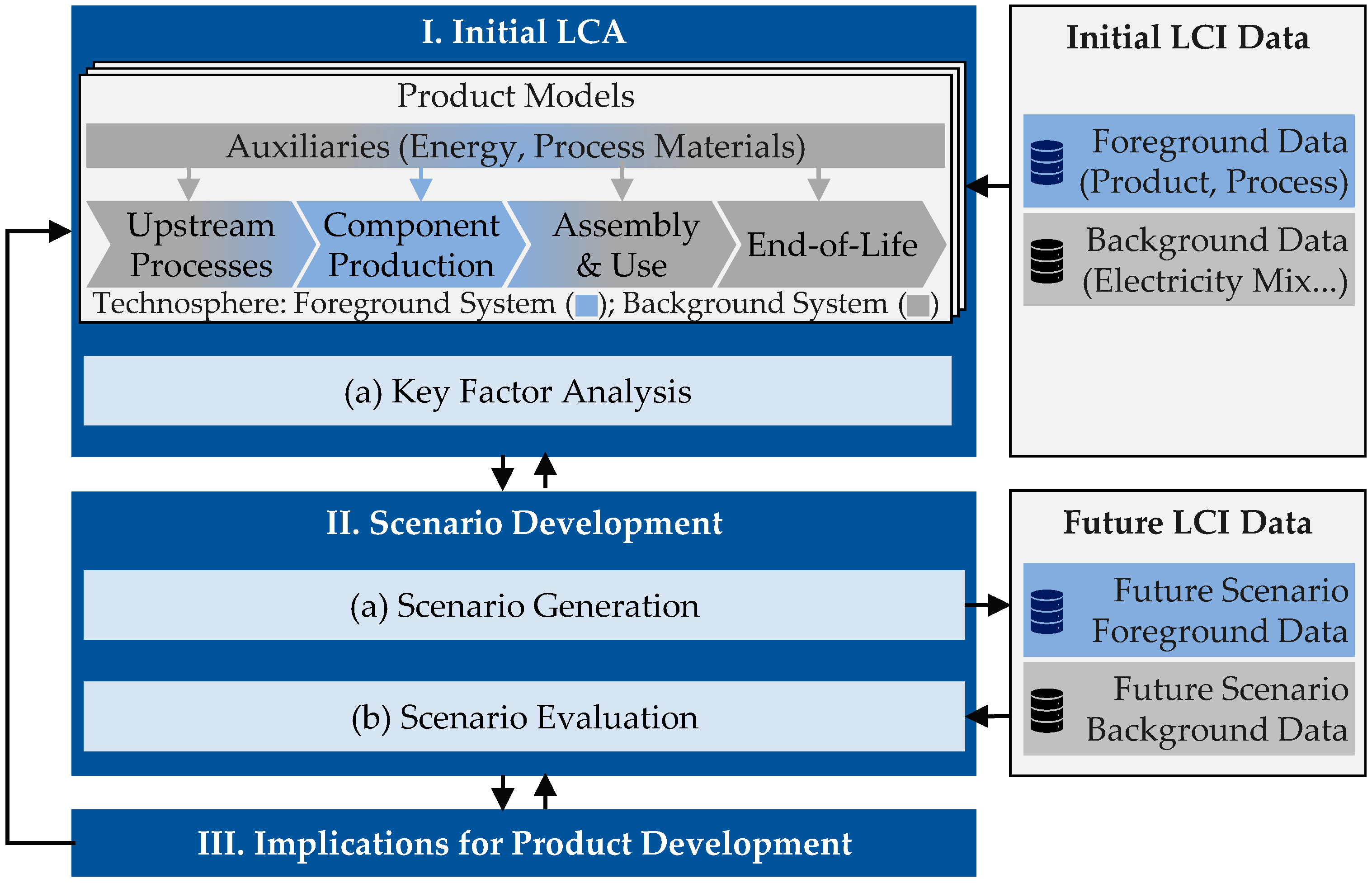
Figure 1. Methodological foundation for integrating prospective LCA in the LCE of lightweight structures comprising three steps.
Energies 16 03371 g001
Figure 2. Exemplary CMS (left) [56] and weights of design alternatives in this study (right).
Energies 16 03371 g002
Figure 3. Manufacturing routes of the three CMS design alternatives.
Energies 16 03371 g003
Figure 4. Results of the initial LCA for the production and use stage of the three CMS design alternatives, showing favourable designs in each life cycle stage and possible break-even points.
Energies 16 03371 g004
Figure 5. Key factor analysis for the background system based on a cradle-to-grave perspective showing the relative contribution of each key factor. Identified key factors for the background system are the material production and the electricity grid mix for the use stage.
Energies 16 03371 g005
Figure 6. Key factor analysis for the foreground system based on a gate-to-gate perspective showing the relative contribution of each key factor. Identified key factors for the foreground system are the energy intensive production processes and the energy demand for the production stage.
Energies 16 03371 g006
Figure 7. Emission intensity of the electricity grid mix for production and use stage—future projections until 2050 for electricity grid mix in Europe based on premise scenario “SSP2-RCP 2.6”.
Energies 16 03371 g007
Figure 8. Emission intensity in kg CO2 eq. for the production of major materials per kilogram material—future projections until 2050: (a) projection for primary aluminium ingot based on [39,40,61]; (b) projection for steel, finished cold-rolled coil based on [37,38,60,72]; (c) projection for epoxy matrix based on [64,73]; (d) projection for carbon fibre based on [14,15,16,41,43,62,73].
Energies 16 03371 g008
Figure 9. GWP of the three design alternatives, including material and part production in 2030 (a), 2040 (b) and 2050 (c) compared to the reference year 2020.
Energies 16 03371 g009
Figure 10. Production and use stage GWP of the three design alternatives: steel design (St.), hybrid design (Hy.) and aluminium design (Al.) for 2030 (a) and 2040 (b).
Energies 16 03371 g010
Disclaimer/Publisher’s Note: The statements, opinions and data contained in all publications are solely those of the individual author(s) and contributor(s) and not of MDPI and/or the editor(s). MDPI and/or the editor(s) disclaim responsibility for any injury to people or property resulting from any ideas, methods, instructions or products referred to in the content.