Abstract
The article presents basic issues associated with the power supply of integrated electronic security systems (IESS) operated in various facilities. Ensuring the reliability of an IESS power supply is an important issue associated with the operation of these systems that are responsible for the safety of people, accumulated property, natural environment, and cooperating structures—e.g., storage facilities. IESSs are operated under harsh external or internal environmental conditions. In such a case, we are dealing with processes of beneficial or adverse impact, which actively affects IESS operation. The IESS operation process is also associated with ensuring power supply continuity under normal operating conditions. This also means ensuring transition to backup power supply systems in the event of failures. Therefore, an IESS should exhibit high reliability related to the power supply process. To this end, the article presents two representative IESSs operated in buildings and in a vast area. The analysis covered the processes of power supply from basic energy sources (BES) and backup sources in cases of failures. The further segment of the article describes developed models of these power systems with acceptable and unacceptable technical states associated with an IESS power supply. The last section of the article defines a model and graph of a selected IESS operation process and describes a conducted computer simulation associated with operational safety. Such an operation process analysis enabled drawing conclusions that can be utilized throughout the entire IESS operation process.
1. Introduction
Integrated Electronic Security Systems (IESS) are intended to provide security in buildings and over vast areas—e.g., buildings and warehouses, railway stations, airports, seaports, etc. [1,2]. In most cases, the aforementioned structures and areas are classified as the so-called State Critical Infrastructure (SCI) [2,3,4]. Therefore, to ensure an adequate security level within these SCI areas, the possibilities provided by the integration of individual electronic security systems (ESS) are applied—e.g., such as those most often used in so-called Smart Buildings (SB): Intrusion Detection System (IDS) and Access Control System (ACS) are often supplemented by Closed-circuit TV (CCTV) [5,6,7]. In this case, all ESS in an SB ensure active internal and external protection (e.g., adjacent garden, playground, or greenery). However, it is the IDS with the CCTV that is the first to decide on generating an alarm signal in the case of a breach of a protection zone(s) intended for a given building, classified as so-called SB or SCI facilities [7,8,9].
1.1. The Utilization of Perimeter Security to Ensure Facility Safety
IESS operation often involves additional peripheral protection measures to secure the aforementioned facilities at approaches—distant in the case of vast area or close-range (fitted on, e.g., fences) for SB. This electronic protection measure enables obtaining additional time for making an intervention decision, conducting the action itself with limited resources, and sending a notification about such actions being taken to superior institutions responsible for the security of such facilities, e.g., Alarm Receiving Centre (ARC—dispatching an intervention patrol), the Police (sabotage, terrorist activity, etc.), and other uniformed services responsible for ensuring safety at—e.g., airports or seaports [10,11,12]. Such organization of the IESS security monitoring process organization enables adopting a specific scenario of a sequence of events in response to a security breach. It is associated with a practical implementation of a matrix of control measures, notifications and the very organization of a procedure related to counteracting adverse actions [13,14,15]. The use of CCTV as part of such a facility security monitoring solution allows also to pre-identify an attack or confirm an alarm signal generated by an IDS [16,17]. This system enables observation and a practical intervention by appropriate services or monitoring this process (e.g., additional people—expanding patrol squads, or the State Fire Service (PSP) in the event of a fire, etc.) [18,19,20]. The implementation of these functions by CCTV is the passive protection of facilities and vast areas—Figure 1 [7,21,22].
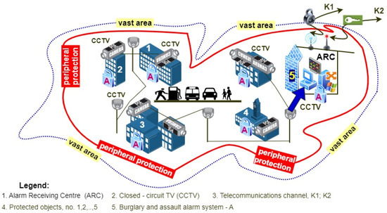
Figure 1.
Simplified diagram of ensuring security over vast areas and in buildings using two electronic security systems—CCTV and IDS. Designations used in the figure are explained in the figure key.
There are two decision-making centres in facilities that operate IESS; one is a local operation and monitoring centre, and the other is an ARC [1,7]. The ARC is connected via two encrypted communication channels (K1, K2) to master units that ensure security and intervention within a specified time, if protection zones are breached—Figure 1. The use of two independent channels to transfer information on IESS technical state (monitoring, alarming and failure) is necessary to ensure reliability [14,23,24]. In such monitored facilities, the ARC is always located where the IESS is operated. Figure 1 shows only some IESSs operated in monitored buildings.
1.2. The Utilization of Integrated Fire Alarm Systems in Facilities
The most important security systems installed in these facilities pursuant to applicable laws and regulations are fire alarm systems (FAS) integrated with audio warning systems (AWS) [7,25,26]. FAS is only integrated with an AWS, while other security systems operated in SB and SCI receive only information on the technical state. FAS and AWS are responsible for security—the health and life of people, and the protection of property and cooperating facilities (e.g., fuel storages). FAS and AWS can be divided by appropriate functional structures into three groups; their functional organization, the connection method of detection circuit, and loop with sensors or broadcast loudspeakers is a function of the area (gross volume) of the protected facilities [15,27,28]. The simplest FAS structures include concentrated (small facilities—surfaces, input and output of detection loops in the Fire Alarm Control Unit (FACU)) and distributed, operated in large, vast facilities, utilizing several to several hundred FACUs with connected sensors that detect Fire Characteristic Values (FCVs) [7,29,30]. A complex FAS is a functional structure that combines the two aforementioned systems [7,15]. When discussing an IESS, the Author of the article deliberately grouped two different security subsystems presented in Figure 1 and Figure 2. These security systems are powered in different ways, also rated by the voltages of the sensors, modules, etc.; and differ, e.g., FAS, AWS—24 V, other IESS—12 V—Figure 2 [7,31,32].
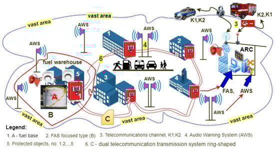
Figure 2.
IESS operated in a vast critical infrastructure area, including a fuel base monitored by a concentrated FAS and a distributed AWS. Individual FACUs (1, 2, …, 5) connected by double telecommunication lines (fibre optic cable) in a ring. Designations used in the figure are explained in the figure key.
Figure 2 shows a simplified organization of two integrated ESS—FAS and AWS [7,13]. The exchange of information between FACU and FAS is required to ensure reliability using a double telecom line ring [14,33,34]. Information on FAS technical state is sent to ARC. The occurrence of an alarm signal in FAS automatically changes the AWS technical state. It switches from monitoring to alarming, activating evacuation and broadcast messages one at a time or collectively in individual fire zones. A supplementation to the ESS operated in SB and SCI and shown in Figure 1 and Figure 2 is the Access Control System (ACS) and a Call System (SP) used in office buildings, hospitals, and shopping centres. These systems are presented in two different Figures due to the clarity of the entire diagram. The correct operation of all IESSs is conditioned upon the functioning of the electric power supply in various technical states of a power system that supplies electricity to SB and SCI areas [13,33,34].
1.3. Power Supply Implementation for Security Systems
Ensuring power supply security for the aforementioned facilities requires the application of various technical and organizational solutions to increase the reliability [19,35,36]. It is implemented in technical systems based on redundancy and the so-called fail-safe principle. It is particularly important in the case of IESS, the task of which is to protect life, property, natural environment, and buildings—Figure 3 [4,37,38].
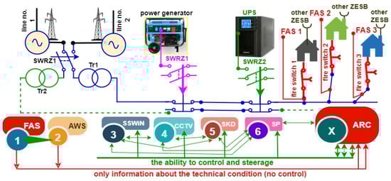
Figure 3.
Power supply for an IESS operated in SB and vast SCI area. Designation: SWRZ1, 1, 2—automatic backup power switch; Tr1, 2—transformer stations; line no. 1, 2—power transmission lines 1, 2; UPS—uninterrupted power supply systems; FAS1, 2, 3—fire alarm systems used in individual buildings; other IESS (ZESB)—other ESS used in the buildings (supplied from an internal power line WLZ of the main cable connection, 1, 2, …, 6 ESB sequence by importance of security measures in SB and SCI areas; X—ARC supervision over an IESS (possible control and information exchange with individual ESB, most usually alarm control units (AWS, SSWiN-intrusion detection system, CCTV, SKD-Access Control Systems, SP-call system); or FAS—please note—only FAS → ARC information exchange).
Supplying power to an IESS operated over vast SCI area is technically achieved taking into account the need to maximize ensured reliability. Redundancy is applied in this case—Figure 3 [39,40,41]. Security systems are powered from two independent power lines connected to a power plant via SWRZ1; failure results in an automatic transition to unloaded backup (line No. 2) [42,43,44]. Failure of power lines 1, 2 leads to an automatic activation of a power generator (AP) with a specific capacity that is sufficient to cover the demand of consumers that have to function during this period (e.g., airport communication, approach radars and ILS, as well as an IESS) [1,45,46]. In the case of AP failure, the power is supplied through a UPS automatically activated by SWRZ2. All FAS operated in buildings, warehouses or in the open are powered via a fire switch (1, 2, 3), as shown in Figure 3. FAS should also be functional during a fire of the aforementioned buildings, for a specified period of time t, which allows the persons supervising a fire-fighting operation to monitor the implementation (or a manual action–control change) of controls executed within the system using a portable LCD panel connected to a FAS [1,7,47,48,49]. Such portable sensor trip indicators located outside of rooms illuminate the evacuation or fire-fighting operation route. Most usually, these indicators are located within building communication routes [4,50,51]. Other IESS operated in buildings are powered with electricity via internal power lines (WLZ), which start at the cable connector (distribution) of the main building—Figure 3. All IESSs are additionally fitted with their own backup power sources—most often in the form of accumulator batteries with a capacity determined based on the energy balance [7,50,51]. The value of capacity is a function of a specified security system operation time during monitoring and alarming, and the current values of equipment and modules connected to an ACU or FAS are at these moments [1,7]. Due to the safety functions of an IESS in an SB and over a vast area are classified as SCI, Figure 3 shows the possible integrations and control measures by the ARC. All IESSs send information on the security status to the ARC; however, it is impossible to conduct current controls and commands via a remote monitoring authority in two systems (FAS, AWS) [14,52,53]. Other security systems are not subject to such restrictions (marked in Figure 3)—mutual control is even possible. A very important operational issue that has to be addressed already at the design stage is ensuring the reliability (security) of the power supply for all IESSs [54,55,56]. An alarm control unit or a FACU act as a power supply (power source) for all elements, sensors, or modules connected to transmission lines and detection loops [7,57,58,59]. Strict requirements regarding power supply technical and functional parameters are defined in the case of IESS [4,7]. Due to the specificity of the current load value in IESS, the FAS power supply voltage is 24 V [7,57,58]. The power supply voltage in other systems is 12 V—Figure 4 [14,59,60,61].
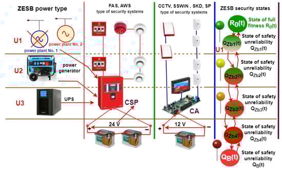
Figure 4.
A solution to an IESS power supply in an SB and vast SCI areas, where: U1, 2, 3—unfitness No. 1, 2, 3, respectively; R0(t)—probability function related to an IESS staying in the SPZ state of full fitness; QZb1(t), QZb2(t), QZb3(t), and QZb4(t)D22(t)—probability functions related to an IESS staying in individual safety hazard states, QB(t)—probability function related to an IESS staying in a state of safety unreliability, and SB—damage to all power supply systems.
1.4. Technical Measures to Improve the FAS Power Supply Reliability Level
Legal regulations on the operation of FAS in buildings do not separately consider issues associated with increasing power supply reliability levels. The issues related to power supply are considered separately for each FAS used in buildings. This important problem of guaranteeing power supply and reliability is also taken into account by a designer of a specific FAS. Therefore, the article presents selected models covering the security of the power supply system operation process that take into account various redundancy solutions applied in such technical objects, which significantly improve power supply continuity reliability. The article also analyses FAS power supply analysis for a single redundancy that increases the reliability level, which is always technically implemented in the form of battery banks. Virtually all security systems utilize permissible redundancies to increase functional reliability—i.e., ensure fire safety. The power supply modelling process presented in the article, which is a computer simulation conducted for all actual operating data of FAS operated in selected buildings and over a vast area, will enable a practical assessment of implementing power supply continuity safety.
2. Literature Review
IESS operated in SB and vast SCI areas require power supply continuity (reliability) in the course of its functioning operation as intended [62,63,64,65].
2.1. Review of IESS Operational Issues Associated with Power Supply Reliability and Quality
Supplying power to facilities within SCI areas requires implementing individual tasks in order to ensure a verified functional reliability level [4,7]. It is most often implemented using a known principle of parametric redundancy [14,66,67,68]. The role of redundant equipment for this purpose is played by a UPS power generator, two independent power lines, and a designated accumulator battery assigned directly to a given electronic security system [68,69,70,71]. According to the Author, the implementation of an operational task (e.g., aircraft landing, passenger check-in, control and passage of railroad vehicles along communication lines, monitoring and leading out ships to sea, etc.) requires incurring specific financial outlays to properly organize the process of supplying power to such facilities [67,72,73,74]. The application of all redundancy types, as well as the so-called fail-safe principles (often used in FACU) are some of the methods to actively improve IESS [3,65,75,76]. This also includes using service teams located at the site where given IESSs are used. Organized and appropriately equipped service teams should attempt a recovery process of a given system immediately after receiving an unfitness signal [77,78]. For this purpose, they should have a so-called “handy” (on-site) spare part warehouse for all IESSs. In order to determine such a warehouse, it is required to keep a repair log for individual systems on an ongoing basis; it should involve determining the damage type, unfit element type, operation time until failure, etc. [67,79,80,81]. According to the Author, such data is often not managed by the service or is incomplete, which hinders reliable development of a spare part list [4,67]. Figure 1, Figure 2, Figure 3 and Figure 4 deliberately do not include technical issues associated with the process of transmitting alarm, failure, and monitoring signals in IESS [82,83,84]. Adding transceivers to all Figures would make them become illegible. According to the Author, particular attention should be paid to the process of transmitting alarm and failure signals from all IESSs [17,85]. Signals should be transmitted undisturbed [67,86,87,88,89].
A very important issue, with regard to the power supply operation process, is its quality (e.g., rated voltage change, harmonics content in the grid, frequency change, interference, etc.), which is the case throughout the entire operation process [7,90,91,92,93]. Electromagnetic interference related to an entire frequency range constitute a considerable problem associated with power supply system operation [15,94,95,96]. The Author believes that low-frequency conducted interference that can propagate through an IESS earthing and power lines requires particular attention [7,16,87,97,98]. The IESS operation process should also take into account the high-frequency interference—e.g., radiation, occurring in the natural environment, radio and TV stations, radar stations, mobile telephony stations, and others [99,100,101,102]. IESS power supplies are equipment in devices and elements that protect an entire power conversion path against interference from this frequency range—e.g., low-pass filter with a specified transmission band, glands, varistors, stabilizers, and shielded power feed cables [7,103,104]. Additionally, mechanical vibrations, especially wall and building partition vibrations, are important in terms of functioning—e.g., of in-line smoke detectors in a FAS [4,105,106]. The IESS operation process should also take temperature, humidity, and pressure changes into account [1,4,7]. It is all associated with the conditions of the natural environment where individual IESS components are operated [14,107,108,109]. The environment directly impacts a change in—e.g., active element polarization points, ionization sensor chamber ionization current, change in smoke detector photodiode currents, etc. [7,110,111,112]. The Author has not encountered IESS operational data that would take the aforementioned interference into account—e.g., electromagnetic interference, level of mechanical vibrations and oscillations or noise on audio warning systems [7,15,113,114].
2.2. Review of Literature Issues Associated with the Diagnosis of IESS, and Processes Related to Possible Natural Environment Interference
A very important issue related to the IESS operation process that has to be ensured in all security systems and for all operation types (detection, alarming or failure) is the process of diagnosing and assessing the technical states [67,91,115,116]. The IESS detection process should be executed continuously, in real time and concurrently with other operation types of these systems [7,67]. However, a generated alarm signal in these security systems should have the highest priority (stops the ESS detection process, failure signal transmission process, etc.), especially in fire alarm systems [1,4,117,118]. Conducting a detection process in systems monitoring “high-volume facilities” requires the use of special microprocessors in CA and FACU that are intended only for implementing this type of a technical actions [7,119,120]. The very development, mapping, and the transmission of diagnostic information to appropriate local or remote stations monitoring the operation of these systems is a very important issue related to IESS. Diagnostic information sent to ARC or a local service team should be modulated using available technical solutions based on modulation processes resistant to natural interference—e.g., digital modulations (amplitudes, frequencies or phases), ASK, FSK, or PSK with encryption [15,67,121,122]. In addition, diagnostic information should be displayed on the LCD panel of an ACU or FACU, and be available in two independent locations, namely, a diagnostic result depiction at the ARC and a portable panel available only to the fire-fighting group commander in the event of a fire within protected facilities [7,19]. According to the Author of the article, in addition to the diagnostic information on the current IESS operation process, the LCD panel or the sent system technical state message should include a forecast related to the impact of a given unfitness on the operation process and R(t) reliability of the entire system or individual facility structures [1,13,67]. The Author believes that current operated security systems lack such forecast or instantaneous diagnoses regarding the IESS operation process implemented at a given time or in the future (predicted ESS behaviour in successive time periods) [67,121,122].
Important issues encountered in the course of IESS operations are associated with the occurrence of intentional or unintentional interference (stationary or mobile) from the natural environment [14,19,67]. These are mechanical interferences related to the vibrations or oscillations of building partitions or the buildings themselves, as well as disturbances of the electromagnetic field [4,13,77]. Additionally, temperature, humidity, or pressure changes within the natural environment indirectly or directly affect the IESS element, device, or module operation process. The occurrence of such interference should be taken into account already at the IESS design stage; however, the Author believes and according to available source literature, there are currently no regulations and legal requirements regarding this issue [78,79,99]. All natural environment measurements should be conducted prior to the IESS design process. This is also aimed at reducing the probability of a false alarm in an IESS, with particular attention to FAS and AWS [1,5,7,19,67].
2.3. Critical Review of Source Literature on the Operation Process of FAS Sensors—Detectors
The elements that determine the detection of such a threat as peripheral or internal protection zone breaches or the changes of a fire characteristic value (FCV) are sensors responding to changes of various physical phenomena associated with extortions [103,107,123]. A sensor built into a detector within a detection line or circuit is always the element that determines threat detection [7,117,124]. It is a device that decides about detecting a threat but also significantly impacts false (alarm) signals generated in the IESS [15,93,125]. Therefore, the Author believes that another important issue is minimizing such false alarms already at the threat information source through the application of modern sensor solutions—e.g., dual (IR and microwave) [65,94,118], multisensors (smoke, temperature or electromagnetic radiation) [58,61,69], and implementing the threat detection process in sensors using artificial neural networks [93,107,119,126].
3. Selected Operation Process Model of a Power Supply Used in Electronic Security Systems Operated in Critical Infrastructure Facilities and in a Vast Area
Integrated electronic security systems operated in buildings and a vast area are classified as distributed (complex) systems—Figure 2. They are used to ensure broadly understood protection of the population, people on the move (land, sea, and air transport), accumulated fixed and mobile property, and the natural environment. Redundancy and the fail-safe principle (in alarm control units) are widely applied in order to guarantee appropriate security system reliability. Virtually all types of redundancy are used in security systems. Information on technical states (e.g., detection, alarming, blocking, or failure, etc.) are transmitted from an ESS to ARC or PSP via two independent telecommunication channels that employ various frequencies, modulations, or signal propagation paths [7,127,128]. In particular, the information on an ESS failure is important for local (within protected facilities) and remote service teams located in the ARC. Receiving information on unfitness within a security system (element type, No., location, diagnosis) leads to immediate commencement of a recovery process covering these technical objects, which tangibly (significantly) reduces the recovery time [1,129,130]. In the case of an ESS operated in critical infrastructure buildings, the local and remote service teams have the so-called “on-site spare part warehouses”, which enable immediate repair–recovery. A process that is particularly important to the entire ESS is the selection of the alarm and failure signal transmission device. Such a device must take into account basic requirements in terms of a used ESS, digital or analogue devices, primary signal modulation types used in systems, as well as the bandwidth of transmitting and receiving links, encryption, and, most importantly, the power supply—without which an ESS would not function in accordance with design assumptions [5,7,131,132].
3.1. Basic Technical Assumptions Regarding FAS Operation Process Associated with Modelling Power Supply Operation
The following technical assumptions were adopted in the course of further considerations regarding the ESS operation process—i.e., elements, modules, and devices used:
- failure rate λ of all devices used within an ESS is constant and non-negative throughout the operation process. Therefore, an exponential distribution can be adopted for the further analysis of an ESS operation. All electronic, electric and electromechanical elements, modules, and devices employed in practice in security systems are subject to a so-called pre-ageing process at manufacturing plants. Its duration and execution methods are agreed to at the manufacturing plant and most often constitutes a trade secret. This process enables early detection of defects and failures for all ESS components and discarding the so-called “infant” period for the failure rate λ intensity curve. Virtually all security systems used in state critical infrastructure facilities are not always operated up to the so-called wear limit threshold [7,13,133,134]. Security systems are always modernized and improved after introducing new sensors or alarm control units. However, most often the ESS modernization process involves replacing the entire security system with a new one that offers complex functionalities detecting a threat process;
- transition to a specific technical state of the electronic security system operation process (detection–alarm, detection–failure, etc.) is always forced by a current implementation of tasks associated with ensuring protection [5,7,135]. A current ESS operation process is not a function that depends on operation and functional history for previous technical states of such a technical object. The current technical state of security systems is always only a function dependent on the current ESS state(s).
Figure 5 shows a diagram of a power supply system for electronic security systems operated in buildings. A diagnostic subsystem, located in the alarm control unit, is used in the ESS to assess the fitness of individual power sources. The information on the technical state of power sources regarding two independent power supply systems is sent to the following recipients:
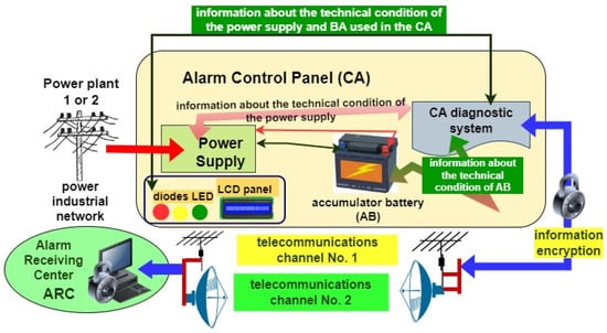
Figure 5.
Diagram of a power supply system for an ESS using two independent power sources, a diagnostic subsystem, and two independent telecommunication channels.
- an alarm control unit LCD front panel in the form of an alphanumeric message and, additionally, LED diode(s) and an audio signaling device in the ACU front panel;
- operational event visualization devices in the ARC and local service team, which are most often a computer set(s) with a dedicated IT application. The app enables ongoing monitoring of the operation process of IESS operated in buildings and a vast area—e.g., an airport, seaport, military unit, etc.
Only two technically independent, different power sources were employed in the considered case of security system power supply:
- an ESS system power supply is always first. It converts electricity from a 230 V 50 Hz industrial grid to 12 V DC for all security systems, except for fire alarm systems, which uses 24 V;
- 12 or (24 V for FAS) accumulator battery, charged and technically monitored by a diagnostic module in the alarm control unit.
Accumulator battery capacity for a specific ESS is always determined based on the energy balance, with two dominant technical operational states—i.e., detection and alarming are considered. Figure 5 shows a power supply diagram for an ESS that employs two basic power sources—i.e., an industrial grid and an accumulator battery. It is also a system for transmitting diagnostic information on the technical states of these devices via two independent telecommunication channels [4,7,136]. When analysing power supply systems for an ESS and information transmission, as shown in Figure 5, it can be concluded that it exhibits a mixed reliability structure. In all cases, ACU failure leads to an ESS transition from the SPZ state of full fitness to the SB state of safety unreliability. An ESS is completely unfit, while telecommunication channels No. 1 and 2 and the accumulator battery are fit. An ACU failure is always critical for the entire ESS. Therefore, the ACU in complex, distributed FAS always has 100% redundant protection; the fail-safe principle is applied [17,21,137].
3.2. Developing Assumptions to a Power Supply Modelling Process and Developing the Process Itself
Given the assumptions above, an operation process model of an ESS that employs two power sources is an ordered triple in the form of a dependency described by the Equation (1).
where the SB state can be described accordingly using the Equation (2).
SB is a set of ESS operational states that can be interpreted as follows:
- SPZ—ESS state of full fitness,
- SZB—ESS safety hazard state No. 1 (power supply and accumulator battery failure after a preset system power supply time for the monitoring and alarm states),
- SB—ESS safety unreliability state.
States belonging to the SB set should be interpreted as states of full fitness, safety hazard No. 1, safety hazard No. 2, and safety unreliability. It is then possible to consider the technical functioning of an electronic security system in terms of model functional safety.
The second element RE, found in the Equation (1) for the ordered M triple, is a set of pairs with elements interpreted as follows:
- informs about the possibility of a transition from the SPZ state to the SZB state, (ESS—fully fit system—ACU power supply and accumulator battery failure related to the device operation time);
- informs about the possibility of a system transition from the SZB state to the SB state (ESS operates using an accumulator battery). After a specified period of time associated with power consumption by operating devices of the security system, the system switches to state SB).
Therefore, the RE element can be described with the Equation (3).
i.e., the RE element can be determined with the Equation (4)
Let us assume that element FR is a set of functions, each of which is determined on the set RE, and adopts a value from a set of positive real numbers—i.e., R+. In particular, the failure rate λ function that characterizes electronic elements, modules, and devices used in ESS has the form defined by the Equation (5).
Therefore, each of the elements in the RE set is assigned a number from the R+ set, interpreting the intensity of transition within a given operational graph for an ESS power supply system. In particular, the following dependencies can be written when describing the ESS power supply system operation process:
- is an interpretation of the intensity of system transition from the SPZ state of full fitness to the SZB state of safety hazard (ESS, power supply failure and accumulator battery discharged due to electricity consumption of the security system equipment);
- is an interpretation of the intensity of system transition from the SZB state of safety hazard to the SB state of safety unreliability—system fully operable;
- is an interpretation of the intensity of system transition from the SPZ state of full fitness to the SB state of safety unreliability—system fully unfit (ESS, damaged due to interference or e.g., atmospheric discharge pulse, power supply failure, or accumulator battery discharge due to electricity consumption of security system equipment).
A graphical interpretation of the aforementioned operational situation of an ESS that employs two independent power supply sources monitored by a diagnostic model is shown in Figure 6.
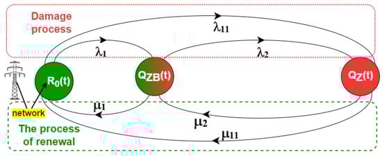
Figure 6.
Example of a power supply operation process for an ESS with one redundant (backup) element in the form of a BA–accumulator battery.
Respective designations in Figure 6:
- -
- RO(t)—probability function of an ESS staying in a state of full fitness–operable power supply from an industrial grid, accumulator battery fully charged;
- -
- QZB(t)—probability function of an ESS staying in a state of safety hazard 1–no power from the industrial grid, system functions based on an accumulator battery with finite capacity Q (specific ESS operation time using a backup power source);
- -
- QZ(t)—probability function of an ESS staying in a state of safety unreliability, industrial grid power supply source failure, accumulator battery available in the security system fully discharged.
The model shown in Figure 6 shall be described with the following Kolmogorov–Chapman equations in order to determine the probabilities of an ESS staying in individual technical states (6). Equation (6) describe the behaviour of the power supply system for the model shown in Figure 6, at time “t”. The power supply system described by Equation (6) takes into account the initial aging of the devices carried out in the production plant.
Adopting initial conditions for ESS functioning in the form of Equation (7). The power supply system for the ESS, after being put into operation, is in a state of full operability—i.e., all elements and devices are operational, R0(0) = 1. The values of the other functions—QZB(t), QB(t)—take the value equal to zero, in accordance with the probability theory.
and applying the Laplace transformaation for the set of Equation (6), we get the following set of linear equations. The system of Equation (8) describes the energy supply system in the domain of the operator calculus. The functions , , and describe the distinguished reliability and operational states of the considered system in symbolic terms.
Applying inverse transformation to the system of Equation (8), we get a function form in symbolic terms, expressed by Equations (9)–(11). Equations (9)–(11) describing the individual technical states of the energy system have been determined based on the inverse Laplace transformation. The designated functions in symbolic terms allow, after performing certain transformations and entering operating data, to determine the values of the functions R0(t), QZB(t), and QB(t) for given time intervals.
The data regarding an ESS power supply and accumulator battery failure rate λ has been obtained through operational test results for n = 20 different sets of security systems operated under the same environmental conditions. The values of failure rate λ and recovery rate μ parameters have been calculated as a mean value of the test result for n = 20 sets of security systems operated in buildings. ESS operation process data adopted for calculating operation process security indicators are presented in Table 1.

Table 1.
ESS operation process data adopted for calculating operation process.
Substituting the data acquired through ESS tests to Equations (9) and (10), we get the following function solutions, expressed as Equations (12)–(14).
A solution to the system of Equations (12)–(14) in the time domain are Equations (15)–(17).
3.3. Results of a Computer Simulation Involving the Developed Basic Power Supply Model
Figure 7 shows the waveform of a probability function related to an ESS staying in a state of full fitness. A security system is powered from an industrial power grid and an accumulator battery, which is treated as a backup power source, is operational. An accumulator battery is fully charged by the security system power supply, which is confirmed by a message sent to the ACU front LCD panel by a diagnostic subsystem located in the alarm control unit, which monitors all security system elements used as part of the functioning—ensuring security.
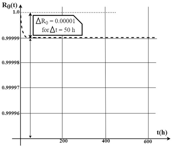
Figure 7.
Waveform of the probability function R0(t) related to electronic security system power supply devices staying in a state of full fitness.
Based on the graph of R0(t) describing the probability of a security system staying in a state of full fitness, it can be concluded that over the time of Δt = 50 [h], the function’s value decreased by only ΔR0(t) = 10·10−6, which is a very low (negligible) value for an entire ESS. Further along the security system operation process—i.e., after a time of t = from 100 to 600 h—the R0(t) function describing the probability of an ESS power supply system in question staying in state of full fitness reaches a constant value equal to R0(t) = 0.99999.
This means that the design, execution, equipment selection, and the ESS power supply system operation process itself have been correct, and its operating environment satisfies the assumptions in terms of changes to such permissible conditions as temperature, humidity, pressure, etc.
Figure 8 shows the waveform of a probability function QZB(t) related to an electronic security system staying in a state of safety hazard—i.e., no electricity supplied by an industrial power grid (unfitness). The security system is powered from an accumulator battery with a specified capacity, which in the perspective of a longer operation process leads to a transition of the operated technical object (ESS in this case) to the state of unfitness—i.e., safety unreliability QB(t).
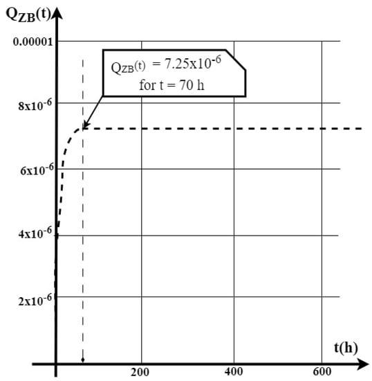
Figure 8.
Waveform of the probability function QZB(t) related to an electronic security system staying in a state of safety hazard.
Figure 9 shows the waveform of a probability function QZ(t) related to an electronic security system staying in a state of safety unreliability. The ESS operation process is a critical case. Failure of the power supply from an industrial grid, accumulator battery available in the security system is fully discharged by flowing alarm currents for individual security system elements, devices and modules within a time period provided for in regulations—most often 15 min for selected ESS. Table 2 presents the values of the FAS probability function at the initial time of use.
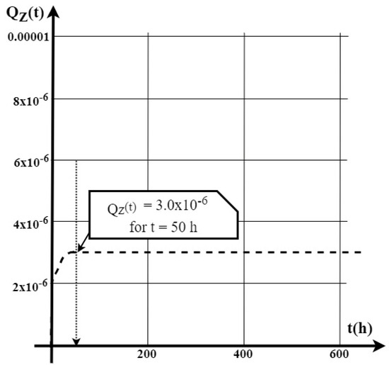
Figure 9.
Waveform of the probability function QZ(t) related to an electronic security system staying in a state of safety unreliability.
Table 2.
Values of the FAS probability function at the initial time of use.
4. Conclusions
The issues related to the operation process of electronic security systems responsible for local and peripheral protection in buildings and over vast areas classified as the so-called state critical infrastructure (e.g., airports, seaports, logistics hubs, railway areas, etc.) is extremely important. All security systems operated within a specific, adverse environment should be characterized by an adequate level of reliability throughout the entire operation process. Figure 7, Figure 8 and Figure 9 show selected waveforms for te probability functions related to the ESS power supply system staying in separate operational states—i.e., full fitness, safety unreliability, and hazards. The probabilities of an ESS staying in a state of safety hazard and unreliability in the initial period of power supply system operation are very low—e.g., QZB(t) is only 7.25·10−6 after Δt = 70 (h), and QZ(t) = 3.0·10−6 after Δt = 50 (h). This proves that failures occurring within the power supply path of electronic security systems during the so-called “infant” period have been practically eliminated. Based on analysing the graph of probability functions related to the electronic security systems staying in a state of full fitness shown in Figure 7, it can be concluded that the R0(t) value at the initial operation period of all ESS power supply equipment reaches an approximated value equal to 1. For an ESS power supply system in the form of a power supply unit and accumulator batteries treated as a backup power source, it can be concluded that after Δt = 50 (h), the value of this R0(t) function, which describes the probability of an ESS staying in a state of full fitness, decreases only to a level of 0.99999. In the case of the same ESS operation process, the other probability functions related to a given technical object staying in the states of safety hazard and unreliability—i.e., QZB(t) and QZ(t)—increase their values over the power supply operation time (Δt = 50 (h)), as shown in Figure 8 and Figure 9. An analysis of these functions depicting the probability of an ESS power supply system’s staying in certain states, especially during the initial operation stage, enables a conclusion that their values are very small; e.g., after Δt = 70 h, the value of the ESS power supply system safety hazards function QZB(t) is only 7.25·10−6, as shown in graph 8. On the other hand, the value of the QZ(t) function, which is the safety unreliability state (full unfitness of the power supply system for the entire ESS) is only 3.0·10−6 after Δt = 50 h. These are very small values, taking into account the waveform of the entire function R0(t) (Figure 7) of the probability for ESS power supply equipment staying in a state of full fitness. As can be seen, after the security system’s initial process, which is after a maximum time of Δt = 70 h, the values of individual waveforms of R0(t) and QZB(t) and Qz(t)Z(t) stabilize. The dominant probability value throughout the further ESS operation period is achieved by the R0(t), function—i.e., the probability of ESS power supply devices staying in a state of full fitness—Figure 7. The value of this function is R0(t) = 0.99999.
Such large probability values of a power supply system of the entire ESS staying in a state of full fitness means that a designer correctly developed the design, as well as selected the elements and equipment, and that the manufacturing process at an industrial plant was also flawless. The conducted computer simulation confirms an important practical aspect related to the functioning of an entire power ESS—i.e., operation process reliability, during the initial operation period in particular. As part of further research, the Author of the article intends to conduct operational tests of ESS operated in other facilities, not classified as critical infrastructure—e.g., single-family houses, small shops, or manufacturing companies.
The achieved FAS power supply reliability level within the initial operation process is at a considerable level and amounts to R0(t) = 0.99999, respectively. The application of only one redundancy for the implementation of the power supply ensures reaching such a high value of the probability for security systems staying in a state of full fitness using only such solutions. For integrated security systems used in the state’s critical infrastructure, double or even triple redundancy is applied to supply power to ensure an adequate level of reliability. FAS operated in single-family buildings or, e.g., small shops, do not require the use of such solutions, which are unfortunately expensive. In addition, they also generate costs associated with their maintenance, diagnosis, and repair throughout their operation process. The application of a power supply solution that utilizes a battery bank in the aforementioned buildings is absolutely sufficient in terms of reliability. Power supply reliability also in the case of FAS operation in such facilities can also be improved through ensuring appropriate maintenance (service), e.g., a minimum failure response time, service available using the so-called on-site spare parts storage, implementation of complex diagnostic procedures with high credibility.
Funding
This work was financed/co-financed by the Military University of Technology under research project UGB 737.
Data Availability Statement
The data presented in this study are available on request from the corresponding author.
Conflicts of Interest
The author declares no conflict of interest.
Abbreviations
| ESS | Electronic Security Systems, |
| FFED | Fixed Fire Extinguishing Devices, |
| IESS | Integrated Electronic Security Systems, |
| AWS | Audio Warning System, |
| MCP | Manual Call Point, |
| kg(t) | availability coefficient, |
| µ | recovery intensity coefficient, |
| λ | failure rate coefficient, |
| RO(t) | probability function of an FAS staying in the SPZ state (full fitness), |
| QZB(t) | probability function of an FAS staying in the SZB state (safety hazard) |
| QB(t) | probability function of an FAS staying in the SPZ state (safety unreliability) |
| λ | failure rate, transition of a selected FAS from the SPZ state to the SZB state, |
| μ | recovery intensity, transition from the SZB state to the SPZ state, |
| TF1–TF9 | test fire designations, |
| AFSTiD | Alarm and Failure Signal Transmission Device, |
| PD1 | detection loop No. 1, |
| λCSP | intensity of transition from the SPZ state of full fitness to the SB state of safety unreliability |
| SB | Smart Building |
| SCI | State Critical Infrastructure |
| FCV | Fire Characteristic Values |
| ACU | Alarm Control Unit |
| FACU | Fire Alarm Control Unit |
| ASK, FSK, PSK | Digital signal modulations: Amplitude-Shift Keying; Frequency-Shift Keying; Phase-Shift Keying. |
| SB | ESS safety unreliability state, |
| SPZ | ESS state of full fitness, |
| SZB | ESS safety hazard state No. 1 (power supply and accumulator battery failure after a preset system power supply time for the monitoring and alarm states), |
| intensity of system transition from the SPZ state of full fitness to the SB state of safety unreliability—system fully unfit. |
References
- Klimczak, T.; Paś, J.; Duer, S.; Rosiński, A.; Wetoszka, P.; Białek, K.; Mazur, M. Selected Issues Associated with the Operational and Power Supply Reliability of Fire Alarm Systems. Energies 2022, 15, 8409. [Google Scholar] [CrossRef]
- Kołowrocki, K.; Soszyńska-Budny, J. Critical Infrastructure Safety Indicators. In Proceedings of the IEEE International Conference on Industrial Engineering and Engineering Management (IEEM), Bangkok, Thailand, 16–19 December 2018; pp. 1761–1764. [Google Scholar]
- Kwasiborska, A.; Skorupski, J. Assessment of the Method of Merging Landing Aircraft Streams in the Context of Fuel Consumption in the Airspace. Sustainability 2021, 13, 12859. [Google Scholar] [CrossRef]
- Dyduch, J.; Paś, J.; Rosiński, A. The Basic of the Exploitation of Transport Electronic Systems; Publishing House of Radom University of Technology: Radom, Poland, 2011. [Google Scholar]
- Klimczak, T.; Paś, J. Selected issues of the reliability and operational assessment of a fire alarm system. Eksploat. Niezawodn. Maint. Reliab. 2019, 21, 553–561. [Google Scholar]
- Madan, M.; Gupta, M.; Liang, J.; Homma, N. Static and Dynamic Neural Networks, From Fundamentals to Advanced Theory; John Wiley & Sons, Inc: Hoboken, NJ, USA, 2003. [Google Scholar] [CrossRef]
- Klimczak, T.; Paś, J. Basics of Exploitation of Fire Alarm Systems in Transport Facilities; Military University of Technology: Warsaw, Poland, 2020. [Google Scholar]
- Manzini, R.; Regattieri, A.; Pham, H.; Ferrari, E. Maintenance for Industrial Systems; Springer: London, UK, 2010. [Google Scholar]
- Ministry of the Interior and Administration of Poland. Regulation of Ministry of the Interior and Administration of Poland (MSWiA) of 7 June 2010 (Journal of Laws of the Republic of Poland No. 109, Item 719) Concerning Fire Protection of Buildings and Other Facilities and Grounds; Ministry of the Interior and Administration of Poland: Warsaw, Poland, 2021. Available online: https://sip.lex.pl/akty-prawne/dzu-dziennik-ustaw/ochronaprzeciwpożarowa-budynkow-innych-obiektow-budowlanych-i-terenow-17626053 (accessed on 17 November 2021).
- Soszyńska-Budny, J. General approach to critical infrastructure safety modelling. In Safety Analysis of Critical Infrastructure. In Lecture Notes in Intelligent Transportation and Infrastructure; Springer: Cham, Switzerland, 2021. [Google Scholar]
- Ziółkowski, J.; Małachowski, J.; Oszczypała, M.; Szkutnik-Rogoż, J.; Lęgas, A. Modelling of the Military Helicopter Operation Process in Terms of Readiness. Def. J. 2021, 71, 602–611. [Google Scholar] [CrossRef]
- Valouch, J. Integrated alarm systems. In Computer Applications for Software Engineering, Disaster Recovery, and Business Continuity; Series: Communications in Computer and Information Science XVIII; Springer: Berlin/Heidelberg, Germany, 2012; Volume 340, pp. 369–379. ISSN 1865-0929. [Google Scholar]
- Duer, S.; Woźniak, M.; Paś, J.; Zajkowski, K.; Ostrowski, A.; Stawowy, M.; Budniak, Z. Reliability Testing of Wind Farm Devices Based on the Mean Time to Failures. Energies 2023, 16, 2827. [Google Scholar] [CrossRef]
- Jakubowski, K.; Paś, J.; Rosiński, A. The Issue of Operating Security Systems in Terms of the Impact of Electromagnetic Interference Generated Unintentionally. Energies 2021, 14, 8591. [Google Scholar] [CrossRef]
- Jakubowski, K.; Paś, J.; Duer, S.; Bugaj, J. Operational Analysis of Fire Alarm Systems with a Focused, Dispersed and Mixed Structure in Critical Infrastructure Buildings. Energies 2021, 14, 7893. [Google Scholar] [CrossRef]
- Li, F.; Chen, S.; Wang, X.; Feng, F. Pedestrian evacuation modeling and simulation on metro platforms considering panic impacts. Procedia-Soc. Behav. Sci. 2014, 138, 314–322. [Google Scholar] [CrossRef]
- Miziuła, P.; Navarro, J. Birnbaum Importance Measure for Reliability Systems with Dependent Components. IEEE Trans. Reliab. 2019, 68, 439–450. [Google Scholar] [CrossRef]
- Shaw, E.; Roper, T.; Nilsson, T.; Lawson, G.; Cobb, S.V.; Miller, D. The heat is on: Exploring user behaviour in a multisensory virtual environment for fire evacuation. In Proceedings of the 2019 CHI Conference on Human Factors in Computing Systems, Glasgow, Scotland, 4–9 May 2019; pp. 1–13. [Google Scholar]
- Krzykowski, M.; Paś, J.; Rosiński, A. Assessment of the level of reliability of power supplies of the objects of critical infrastructure. IOP Conf. Ser. Earth Environ. Sci. 2019, 214, 012018. [Google Scholar] [CrossRef]
- Zieja, M.; Szelmanowski, A.; Pazur, A.; Kowalczyk, G. Computer Life-Cycle Management System for Avionics Software as a Tool for Supporting the Sustainable Development of Air Transport. Sustainability 2021, 13, 1547. [Google Scholar] [CrossRef]
- Guerrero, J.M.; Chandorkar, M.; Lee, T.-L.; Loh, P.C. Advanced control architectures for intelligent microgrids: Part I: Decentralized and hierarchical control. IEEE Trans. Ind. Electron. 2013, 60, 1254–1262. [Google Scholar] [CrossRef]
- Cheng, Z.; Duan, J.; Chow, M. To Centralize or to Distribute: That Is the Question: A Comparison of Advanced Microgrid Management Systems. IEEE Ind. Electron. Mag. 2018, 12, 6–24. [Google Scholar] [CrossRef]
- Vandoorn, T.L.; Vasquez, J.C.; de Kooning, J.; Guerrero, J.M.; Vandevelde, L. Microgrids: Hierarchical control and an overview of the control and reserve management strategies. IEEE Ind. Electron. Mag. 2013, 7, 42–55. [Google Scholar] [CrossRef]
- Ernst, D.; Glavic, M.; Capitanescu, F.; Wehenkel, L. Reinforcement Learning Versus Model Predictive Control: A Comparison on a Power System Problem. IEEE Trans. Syst. Man Cybern. Part B 2009, 39, 517–529. [Google Scholar] [CrossRef]
- Wang, C.; Yu, H.; Chai, L.; Liu, H.; Zhu, B. Emergency Load Shedding Strategy for Microgrids Based on Dueling Deep Q-Learning. IEEE Access 2021, 9, 19707–19715. [Google Scholar] [CrossRef]
- Jiang, W.; Fahimi, B. Multiport Power Electronic Interface—Concept, Modelling, and Design. IEEE Trans. Power Electron. 2011, 26, 1890–1900. [Google Scholar] [CrossRef]
- Shamsi, P.; Fahimi, B. Dynamic Behavior of Multiport Power Electronic Interface under Source/Load Disturbances. IEEE Trans. Ind. Electron. 2013, 60, 4500–4511. [Google Scholar] [CrossRef]
- Maharjan, L.; Ditsworth, M.; Fahimi, B. Critical Reliability Improvement Using Q-Learning-Based Energy Management System for Microgrids. Energies 2022, 15, 8779. [Google Scholar] [CrossRef]
- Xiang, W.; Yang, S.; Adam, G.P.; Zhang, H.; Zuo, W.; Wen, J. DC fault protection algorithms of MMC-HVDC grids: Fault analysis, methodologies, experimental validations, and future trends. IEEE Trans. Power Electron. 2021, 36, 11245–11264. [Google Scholar] [CrossRef]
- Wang, T.; Liang, L.; Feng, X.; Ponci, F.; Monti, A. Online parameter estimation for fault identification in multi-terminal DC distribution grids. Energies 2021, 14, 5630. [Google Scholar] [CrossRef]
- He, Y.; Zhang, X.; Wang, R.; Cheng, M.; Gao, Z.; Zhang, Z.; Yu, W. Faulty section location method based on dynamic time warping distance in a resonant grounding system. Energies 2022, 15, 4923. [Google Scholar] [CrossRef]
- Florkowski, M.; Kuniewski, M.; Zydroń, P. Measurements and analysis of partial discharges at HVDC voltage with AC components. Energies 2022, 15, 2510. [Google Scholar] [CrossRef]
- Paś, J.; Rosiński, A.; Wetoszka, P.; Białek, K.; Klimczak, T.; Siergiejczyk, M. Assessment of the Impact of Emitted Radiated Interference Generated by a Selected Rail Traction Unit on the Operating Process of Trackside Video Monitoring Systems. Electronics 2022, 11, 2554. [Google Scholar] [CrossRef]
- Chao, C.; Zheng, X.; Weng, Y.; Liu, Y.; Gao, P.; Nengling, T. Adaptive distance protection based on the analytical model of additional impedance for inverter-interfaced renewable power plants during asymmetrical faults. IEEE Trans. Power Deliv. 2022, 37, 3823–3834. [Google Scholar] [CrossRef]
- Araneo, R.; Celozzi, S.; Lauria, S.; Stracqualursi, E.; Di Lorenzo, G.; Graziani, M. Recent Trends in Power Systems Modeling and Analysis. Energies 2022, 15, 9242. [Google Scholar] [CrossRef]
- Piotrowska-Woroniak, J. The Photovoltaic Installation Application in the Public Utility Building. Ecol. Chem. Eng. S 2017, 24, 517–538. [Google Scholar] [CrossRef]
- Żukowski, M.; Woroniak, G.; Piotrowska-Woroniak, J. Experimental research and numerical simulations of a ceramic panel used for solar energy conversion. Sol. Energy 2019, 194, 27–36. [Google Scholar] [CrossRef]
- Kwade, A.; Haselrieder, W.; Leithoff, R.; Modlinger, A.; Dietrich, F.; Droeder, K. Current status and challenges for automotive battery production technologies. Nat. Energy 2018, 3, 290–300. [Google Scholar] [CrossRef]
- Nitta, N.; Wu, F.; Lee, J.T.; Yushin, G. Li-ion battery materials: Present and future. Mater. Today 2015, 18, 252–264. [Google Scholar] [CrossRef]
- Schmuch, R.; Wagner, R.; Hörpel, G.; Placke, T.; Winter, M. Performance and cost of materials for lithium-based rechargeable automotive batteries. Nat. Energy 2018, 3, 267–278. [Google Scholar] [CrossRef]
- Cavers, H.; Molaiyan, P.; Abdollahifar, M.; Lassi, U.; Kwade, A. Perspectives on Improving the Safety and Sustainability of High Voltage Lithium-Ion Batteries Through the Electrolyte and Separator Region. Adv. Energy Mater. 2022, 12, 2200147. [Google Scholar] [CrossRef]
- Meda, U.S.; Lal, L.; Sushantha, M.; Garg, P. Solid Electrolyte Interphase (SEI), a boon or a bane for lithium batteries: A review on the recent advances. J. Energy Storage 2021, 47, 103564. [Google Scholar] [CrossRef]
- Wawrzyński, W.; Zieja, M.; Tomaszewska, J.; Michalski, M. Reliability Assessment of Aircraft Commutators. Energies 2021, 14, 7404. [Google Scholar] [CrossRef]
- Li, F.-S.; Wu, Y.-S.; Chou, J.; Wu, N.-L. A dimensionally stable and fast-discharging graphite–silicon composite Li-ion battery anode enabled by electrostatically self-assembled multifunctional polymer-blend coating. Chem. Commun. 2015, 51, 8429–8431. [Google Scholar] [CrossRef]
- Wang, Q.; Zhu, M.; Chen, G.; Dudko, N.; Li, Y.; Liu, H.; Shi, L.; Wu, G.; Zhang, D. High-Performance Microsized Si Anodes for Lithium-Ion Batteries: Insights into the Polymer Configuration Conversion Mechanism. Adv. Mater. 2022, 34, 2109658. [Google Scholar] [CrossRef]
- Muhammad, N.; Yasin, G.; Li, A.; Chen, Y.; Saleem, H.M.; Liu, R.; Li, D.; Sun, Y.; Zheng, S.; Chen, X. Volumetric buffering of manganese dioxide nanotubes by employing ‘as is’ graphene oxide: An approach towards stable metal oxide anode material in lithium-ion batteries. J. Alloys Compd. 2020, 842, 155803. [Google Scholar] [CrossRef]
- Antosz, K.; Machado, J.; Mazurkiewicz, D.; Antonelli, D.; Soares, F. Systems Engineering: Availability and Reliability. Appl. Sci. 2022, 12, 2504. [Google Scholar] [CrossRef]
- Agrawal, A.K.; Murthy, V.; Chattopadhyaya, S. Investigations into reliability, maintainability and availability of tunnel boring machine operating in mixed ground condition using Markov chains. Eng. Fail. Anal. 2019, 105, 477–489. [Google Scholar] [CrossRef]
- Odeyar, P.; Apel, D.; Hall, R.; Zon, B.; Skrzypkowski, K. A Review of Reliability and Fault Analysis Methods for Heavy Equipment and Their Components Used in Mining. Energies 2022, 15, 6263. [Google Scholar] [CrossRef]
- Rahimdel, M.J.; Ataei, M.; Ghodrati, B. Modeling and simulation approaches for reliability analysis of drilling machines. J. Inst. Eng. Ser. C 2020, 101, 125–133. [Google Scholar] [CrossRef]
- Ahmadi, S.; Moosazadeh, S.; Hajihassani, M.; Moomivand, H.; Rajaei, M. Reliability, availability and maintainability analysis of the conveyor system in mechanized tunneling. Measurement 2019, 145, 756–764. [Google Scholar] [CrossRef]
- Rahm, T.; Scheffer, M.; Thewes, M.; König, M.; Duhme, R. Evaluation of disturbances in mechanized tunneling using proces simulation. Comput.-Aided Civ. Infrastruct. Eng. 2016, 31, 176–192. [Google Scholar] [CrossRef]
- Frough, O.; Torabi, S.R.; Yagiz, S. Application of RMR for estimating rock-mass–related TBM utilization and performance parameters: A case study. Rock Mech. Rock Eng. 2015, 48, 1305–1312. [Google Scholar] [CrossRef]
- Barabady, J.; Kumar, U. Reliability analysis of mining equipment: A case study of a crushing plant at Jajarm Bauxite Mine in Iran. Reliab. Eng. Syst. Saf. 2008, 93, 647–653. [Google Scholar] [CrossRef]
- Roelen, A.; Van Aalst, R.; Karanikas, N.; Ksapers, S.; Piric, S.; De Boer, J. Effectiveness of risk controls as indicator of safety performance. AUP Adv. 2018, 1, 175–189. [Google Scholar] [CrossRef]
- Moreno, V.C.; Guglielmi, D.; Cozzani, V. Identification of critical safety barriers in biogas facilities. Reliab. Eng. Syst. Saf. 2018, 169, 81–94. [Google Scholar] [CrossRef]
- Li, Y.; Guldenmund, F.W. Safety management systems: A broad overview of the literature. Saf. Sci. 2018, 103, 94–123. [Google Scholar] [CrossRef]
- Zhang, W.; Zhang, X.; Luo, X.; Zhao, T. Reliability model and critical factors identification of construction safety management based on system thinking. J. Civ. Eng. Manag. 2019, 25, 362–379. [Google Scholar] [CrossRef]
- Pas, J.; Klimczak, T.; Rosinski, A.; Stawowy, M. The analysis of the operational process of a complex fire alarm system used in transport facilities. Build. Simul. 2022, 15, 615–629. [Google Scholar] [CrossRef]
- Chan, A.P.C.; Yang, Y.; Darko, A. Construction Accidents in a Large-Scale Public Infrastructure Project: Severity and Prevention. J. Constr. Eng. Manag. 2018, 144, 05018010. [Google Scholar] [CrossRef]
- Filizzola, C.; Corrado, R.; Marchese, F.; Mazzeo, G.; Paciello, R.; Pergola, N.; Tramutoli, V. Rst-fires an exportable algorithm for early fire detection and monitoring: Description implementation and field validation in the case of the msg-seviri sensor. Remote Sens. Environ. 2016, 186, 196–216. [Google Scholar] [CrossRef]
- Rychlicki, M.; Kasprzyk, Z.; Rosiński, A. Analysis of Accuracy and Reliability of Different Types of GPS Receivers. Sensors 2020, 20, 6498. [Google Scholar] [CrossRef]
- Liu, P.; Wang, G. Optimal periodic preventive maintenance policies for systems subject to shocks. Appl. Math. Model. 2021, 93, 101–114. [Google Scholar] [CrossRef]
- Hulida, E.; Pasnak, I.; Koval, O.; Tryhuba, A. Determination of the Critical Time of Fire in the Building and Ensure Successful Evacuation of People. Period. Polytech. Civ. Eng. 2019, 63, 308–316. [Google Scholar] [CrossRef]
- Kou, L.; Chu, B.; Chen, Y.; Qin, Y. An Automatic Partition Time-Varying Markov Model for Reliability Evaluation. Appl. Sci. 2022, 12, 5933. [Google Scholar] [CrossRef]
- Fridolf, K.; Nilsson, D.; Frantzich, H. Fire Evacuation in Underground Transportation Systems: A Review of Accidents and Empirical Research. Fire Technol. 2013, 49, 451–475. [Google Scholar] [CrossRef]
- Stawowy, M.; Duer, S.; Paś, J.; Wawrzyński, W. Determining information quality in ICT systems. Energies 2021, 14, 5549. [Google Scholar] [CrossRef]
- Paś, J. Operation of Electronic Transportation Systems; Publishing House University of Technology and Humanities: Radom, Poland, 2015. [Google Scholar]
- Duer, S.; Scaticailov, S.; Paś, J.; Duer, R.; Bernatowicz, D. Taking decisions in the diagnostic intelligent systems on the basis information from an artificial neural network. In Proceedings of the 22nd International Conference on Innovative Manufacturing Engineering and Energy—IManE&E 2018, MATECWeb of Conferences 178, Chișinău, Moldova, 31 May–2 June 2018; Volume 178, pp. 1–6. [Google Scholar]
- Keding, L. An optimization of intelligent fire alarm system for high-rise building based on ANASYS. In Intelligence Computation and Evolutionary Computation; Du, Z., Ed.; Springer: Berlin/Heidelberg, Germany, 2013; pp. 415–421. [Google Scholar]
- Zhao, H.; Schwabe, A.; Schläfli, F.; Thrash, T.; Aguilar, L.; Dubey, R.K.; Karjalainen, J.; Hölscher, C.; Helbing, D.; Schinazi, V.R. Fire evacuation supported by centralized and decentralized visual guidance systems. Saf. Sci. 2022, 145, 105451. [Google Scholar] [CrossRef]
- Młynarski, S.; Pilch, R.; Smolnik, M.; Szybka, J.; Wiązania, G. A model of an adaptive strategy of preventive maintenance of complex technical objects. Eksploat. Niezawodn. Maint. Reliab. 2020, 22, 35–41. [Google Scholar] [CrossRef]
- Duer, S.; Zajkowski, K.; Harničárová, M.; Charun, H.; Bernatowicz, D. Examination of Multivalent Diagnoses Developed by a Diagnostic Program with an Artificial Neural Network for Devices in the Electric Hybrid Power Supply System “House on Water”. Energies 2021, 14, 2153. [Google Scholar] [CrossRef]
- Duer, S.; Valicek, J.; Paś, J.; Stawowy, M.; Bernatowicz, D.; Duer, R.; Walczak, M. Neural Networks in the Diagnostics Process of Low-Power Solar Plant Devices. Energies 2021, 14, 2719. [Google Scholar] [CrossRef]
- Duer, S. Diagnostic system for the diagnosis of a reparable technical object, with the use of an artificial neural network of RBF type. Neural Comput. Appl. 2010, 19, 691–700. [Google Scholar] [CrossRef]
- Paś, J.; Rosiński, A.; Białek, K. A reliability-exploitation analysis of a static converter taking into account electromagnetic interference. Transp. Telecommun. 2021, 22, 217–229. [Google Scholar] [CrossRef]
- Białoń, A.; Białek, K.; Wetoszka, P. Analysis of emission tests of electromagnetic disturbancesin diesel-electric locomotives. 2nd International Scientific and Practical Conference “Energy-Optimal Technologies, Logistic and Safety on Transport” (EOT-2019). MATEC Web Conf. 2019, 294, 02001. [Google Scholar] [CrossRef]
- Pas, J.; Rosinski, A.; Chrzan, M.; Bialek, K. Reliability-operational analysis of the LED lighting module including electromagnetic interference. IEEE Trans. Electromagn. Compat. 2020, 62, 2747–2758. [Google Scholar] [CrossRef]
- Paś, J.; Rosiński, A.; Białek, K. A reliability-operational analysis of a track-side CCTV cabinet taking into account interference. Bull. Pol. Acad. Sci. Tech. Sci. 2021, 69, e136747. [Google Scholar]
- Dziula, P.; Paś, J. Low Frequency Electromagnetic Interferences Impact on Transport Security Systems Used inWide Transport Areas. TransNav Int. J. Mar. Navig. Saf. Sea Transp. 2018, 12, 251–258. [Google Scholar]
- Mutlu, N.G.; Altuntas, S. Risk analysis for occupational safety and health in the textile industry: Integration of FMEA, FTA, and BIFPET methods. Int. J. Ind. Ergon. 2019, 72, 222–240. [Google Scholar] [CrossRef]
- Soliman, H.; Sudan, K.; Mishra, A. A smart forest-fire early detection sensory system: Another approach of utilizing wireless sensor and neural networks. In Proceedings of the 2010 IEEE Sensors, Waikoloa, HI, USA, 1–4 November 2010; Institute of Electrical and Electronics Engineers (IEEE): New York, NY, USA, 2010; pp. 1900–1904. [Google Scholar]
- Borucka, A.; Niewczas, A.; Hasilova, K. Forecasting the readiness of special vehicles using the semi-Markov model. Eksploat. Iniezawodnosc-Maint. Reliab. 2019, 21, 662–669. [Google Scholar] [CrossRef]
- Dziula, P.; Kołowrocki, K.; Soszyńska-Budny, J. Maritime Transportation System Safety-Modeling and Identification. TransNav. Int. J. Mar. Navig. Saf. Transp. 2013, 7, 169–175. [Google Scholar] [CrossRef]
- Oszczypała, M.; Ziółkowski, J.; Małachowski, J. Analysis of Light Utility Vehicle Readiness in Military Transportation Systems Using Markov and Semi-Markov Processes. Energies 2022, 15, 5062. [Google Scholar] [CrossRef]
- Chrzan, M.; Kornaszewski, M.; Ciszewski, T. Renovation of marine telematics objects in the process of exploitation. In Management Perspective for Transport Telematics; Springer: Cham, Switzerland, 2018; pp. 337–351. [Google Scholar]
- Żyluk, A.; Kuźma, K.; Grzesik, N.; Zieja, M.; Tomaszewska, J. Fuzzy Logic in Aircraft Onboard Systems Reliability Evaluation—A New Approach. Sensors 2021, 21, 7913. [Google Scholar] [CrossRef]
- Świderski, A.; Jóźwiak, A.; Jachimowski, R. Operational quality measures of vehicles applied for the transport services evaluation using artificial neural networks. Eksploat. Niezawodn. Maint. Reliab. 2018, 20, 292–299. [Google Scholar] [CrossRef]
- Andrzejczak, K.; Bukowski, L. A method for estimating the probability distribution of the lifetime for new technical equipment based on expert judgement. Eksploat. Niezawodn. Maint. Reliab. 2021, 23, 757–769. [Google Scholar] [CrossRef]
- Duer, S. Examination of the reliability of a technical object after its regeneration in a maintenance system with an artificial neural network. Neural Comput. Appl. 2012, 21, 523–534. [Google Scholar] [CrossRef]
- Caban, D.; Walkowiak, T. Dependability analysis of hierarchically composed system-of-systems. In Proceedings of the Thirteenth International Conference on Dependability and Complex Systems DepCoS-RELCOMEX, Brunów, Poland, 2–6 July 2018; Springer: Cham, Switzerland, 2019; pp. 113–120. [Google Scholar] [CrossRef]
- Duer, S.; Rokosz, K.; Zajkowski, K.; Bernatowicz, D.; Ostrowski, A.; Woźniak, M.; Iqbal, A. Intelligent Systems Supporting the Use of Energy Devices and Other Complex Technical Objects: Modeling, Testing, and Analysis of Their Reliability in the Operating Process. Energies 2022, 15, 6414. [Google Scholar] [CrossRef]
- Ying, X.; Zhang, X.P.; Yang, C. Commutation failure elimination of LCC HVDC systems using thyristor-based controllable capacitors. IEEE Trans. Power Deliv. 2017, 33, 1448–1458. [Google Scholar]
- Gupta, S.; Kanwar, S.; Kashyap, M. Performance characteristics and assessment of fire alarm system. Mater. Today Proc. 2022, 57, 2036–2040. [Google Scholar] [CrossRef]
- Østrem, L.; Sommer, M. Inherent fire safety engineering in complex road tunnels—Learning between industries in safety management. Saf. Sci. 2021, 134, 105062. [Google Scholar] [CrossRef]
- Bae, J.; Lee, M.; Shin, C. A Data-Based Fault-Detection Model for Wireless Sensor Networks. Sustainability 2019, 11, 6171. [Google Scholar] [CrossRef]
- Wang, H.; Pham, H. Some maintenance models and availability with imperfect maintenance in production systems. Ann. Oper. Res. 1999, 91, 305–318. [Google Scholar] [CrossRef]
- Stawowy, M.; Perlicki, K.; Sumiła, M. Comparison of uncertainty multilevel models to ensure ITS services. In Safety and Reliability: Theory and Applications, Proceedings of the European Safety and Reliability Conference ESREL 2017, Portoroz, Slovenia, 18–22 June 2017; Cepin, M., Bris, R., Eds.; CRC Press/Balkema: London, UK, 2017; pp. 2647–2652. [Google Scholar]
- Zajkowski, K. Two-stage reactive compensation in a three-phase four-wire systems at nonsinusoidal periodic waveforms. Electr. Power Syst. Res. 2020, 184, 106296. [Google Scholar] [CrossRef]
- Suproniuk, M.; Paś, J. Analysis of electrical energy consumption in a public utility buildings. Przegl. Elektr. 2019, 95, 97–100. [Google Scholar]
- Nor, N.M.; Hassan, C.R.C.; Hussain, M.A. A review of data-driven fault detection and diagnosis methods: Applications in chemical process systems. Rev. Chem. Eng. 2019, 36, 513–553. [Google Scholar] [CrossRef]
- Zajkowski, K.; Rusica, I.; Palkova, Z. The use of CPC theory for energy description of two nonlinear receivers. MATEC Web Conf. 2018, 178, 09008. [Google Scholar] [CrossRef]
- Lewczuk, K.; Kłodawski, M.; Gepner, P. Energy Consumption in a Distributional Warehouse: A Practical Case Study for Different Warehouse Technologies. Energies 2021, 14, 2709. [Google Scholar] [CrossRef]
- Łukasiak, J.; Rosiński, A.; Wiśnios, M. The Impact of Temperature of the Tripping Thresholds of Intrusion Detection System Detection Circuits. Energies 2021, 14, 6851. [Google Scholar] [CrossRef]
- Stawowy, M.; Rosiński, A.; Siergiejczyk, M.; Perlicki, K. Quality and Reliability-Exploitation Modeling of Power Supply Systems. Energies 2021, 14, 2727. [Google Scholar] [CrossRef]
- Clavijo, N.; Melo, A.; Câmara, M.M.; Feital, T.; Anzai, T.K.; Diehl, F.C.; Thompson, P.H.; Pinto, J.C. Development and Application of a Data-Driven System for Sensor Fault Diagnosis in an Oil Processing Plant. Processes 2019, 7, 436. [Google Scholar] [CrossRef]
- Variny, M.; Jediná, D.; Kizek, J.; Illés, P.; Lukáč, L.; Janošovský, J.; Lesný, M. An Investigation of the Techno-Economic and Environmental Aspects of Process Heat Source Change in a Refinery. Processes 2019, 7, 776. [Google Scholar] [CrossRef]
- Ragab, A.; El-Koujok, M.; Poulin, B.; Amazouz, M.; Yacout, S. Fault diagnosis in industrial chemical processes using inter-pretable patterns based on Logical Analysis of Data. Expert Syst. Appl. 2018, 95, 368–383. [Google Scholar] [CrossRef]
- Siergiejczyk, M.; Pas, J.; Rosinski, A. Modeling of Process of Maintenance of Transport Systems Telematics with Regard to Electromagnetic Interferences. Tools of Transport Telematics. Book Series Communications in Computer and Information Science. In Proceedings of the 15th International Conference on Transport Systems Telematics (TST), Wrocław, Poland, 15–17 April 2015; Volume 531, pp. 99–107. [Google Scholar] [CrossRef]
- Kaniewski, P. Extended Kalman Filter with Reduced Computational Demands for Systems with Non-Linear Measurement Models. Sensors 2020, 20, 1584. [Google Scholar] [CrossRef]
- Chrzan, M. Effect of uniform time on the transmission of signals in rail open systems. Arch. Transp. 2022, 61, 39–49. [Google Scholar] [CrossRef]
- Davidy, A. CFD Simulation of Forced Recirculating Fired Heated Reboilers. Processes 2020, 8, 145. [Google Scholar] [CrossRef]
- Liu, L.; Sun, R.; Sun, Y.; Al-Sarawi, S. A smart bushfire monitoring and detection system using GSM technology. Int. J. Comput. Aided Eng. Technol. 2010, 2, 218–233. [Google Scholar] [CrossRef]
- Zhang, Q.; Wang, Y.; Soutis, C.; Gresil, M. Development of a fire detection and suppression system for a smart air cargo container. Aeronaut. J. 2020, 125, 205–222. [Google Scholar] [CrossRef]
- Smolenski, R.; Lezynski, P.; Bojarski, J.; Drozdz, W.; Long, L.C. Electromagnetic compatibility assessment in multiconverter power systems—Conducted interference issues. Measurement 2020, 165, 108119. [Google Scholar] [CrossRef]
- Polak, R.; Laskowski, D.; Matyszkiel, R.; Łubkowski, P.; Konieczny, Ł.; Burdzik, R. Optimizing the data flow in a network communication between railway nodes. In Research Methods and Solutions to Current Transport Problems. In Proceedings of the International Scientific Conference Transport of the 21st Century, Advances in Intelligent Systems and Computing, Ryn, Poland, 9–12 June 2019; Siergiejczyk, M., Krzykowska, K., Eds.; Springer: Cham, Switzerland, 2020; Volume 1032, pp. 351–362. [Google Scholar]
- Suproniuk, M.; Skibko, Z.; Stachno, A. Diagnostics of some parameters of electricity generated in wind farms. Prz. Elektr. 2019, 95, 105–108. [Google Scholar]
- Evalina, N.; Azis, H.A. Implementation and design gas leakage detection system using ATMega8 microcontroller. IOP Conf. Ser. Mater. Sci. Eng. 2020, 821, 012049. [Google Scholar] [CrossRef]
- Paś, J.; Rosiński, A. Selected issues regarding the reliability-operational assessment of electronic transport systems with regard to electromagnetic interference. Eksploat. Niezawodnosc–Maint. Reliab. 2017, 19, 375–381. [Google Scholar] [CrossRef]
- Buemi, A.; Giacalone, D.; Naccari, F.; Spampinato, G. Efficient fire detection using fuzzy logic. In Proceedings of the 2016 IEEE 6th International Conference on Consumer Electronics Berlin (ICCE-Berlin), Berlin, Germany, 5–7 September 2016; pp. 237–240. [Google Scholar]
- Huang, X.; Du, L. Fire Detection and Recognition Optimization Based on Virtual Reality Video Image. IEEE Access 2020, 8, 77951–77961. [Google Scholar] [CrossRef]
- Song, S.; Coit, D.W.; Feng, Q. Reliability for systems of degrading components with distinct component shock sets. Reliability Eng. Syst. Saf. 2014, 132, 115–124. [Google Scholar] [CrossRef]
- Vasile, D.-C.; Svasta, P.; Pantazica, M. Preventing the Temperature Side Channel Attacks on Security Circuits. In Proceedings of the 2019 IEEE 25th International Symposium for Design and Technology in Electronic Packaging (SIITME), Cluj-Napoca, Romania, 23–26 October 2019; IEEE: Piscataway Township, NJ, USA, 2019; pp. 244–247. [Google Scholar]
- Weese, M.; Martinez, W.; Megahed, F.M.; Jones-Farmer, L.A. Statistical Learning Methods Applied to Process Monitoring: An Overview and Perspective. J. Qual. Technol. 2016, 48, 4–24. [Google Scholar] [CrossRef]
- Wisnios, M.; Pas, J. The assessment of exploitation process of power for access control system. In Proceedings of the International Conference Energy, Environment and Material Systems (EEMS 2017), Book SeriesE3S Web of Conferences, Polanica-Zdroj, Poland, 13–15 September 2017; Volume 19. [Google Scholar] [CrossRef]
- e Almeida, R.V.; Crivellaro, F.; Narciso, M.; Sousa, A.I.; Vieira, P. Bee2Fire: A deep learning powered forest fire detection system. In Proceedings of the ICAART 2020—12th International Conference on Agents and Artificial Intelligence, Valletta, Malta, 22–24 February 2020; SciTePress: Setúbal Municipality, Portugal, 2020; Volume 2, pp. 603–609. [Google Scholar]
- Zhou, Q.; Xu, Y.; Qi, X.; Zhang, Z. Design and Simulation of a Highly Reliable Modular High-Power Current Source. Energies 2022, 15, 8593. [Google Scholar] [CrossRef]
- Zhang, W.; Xu, D.; Enjeti, P.N.; Li, H.; Hawke, J.T.; Krishnamoorthy, H.S. Survey on fault-tolerant techniques for power electronic converters. IEEE Trans. Power Electron. 2014, 29, 6319–6331. [Google Scholar] [CrossRef]
- Zajkowski, K.; Duer, S.; Paś, J.; Pokorádi, L. Cooperation of a Non-Linear Receiver with a Three-Phase Power Grid. Energies 2023, 16, 1418. [Google Scholar] [CrossRef]
- Vinogradov, A.; Bolshev, V.; Vinogradova, A.; Jasiński, M.; Sikorski, T.; Leonowicz, Z.; Goňo, R.; Jasińska, E. Analysis of the power supply restoration time after failures in power transmission lines. Energies 2020, 13, 2736. [Google Scholar] [CrossRef]
- Chen, G.; Chen, L.; Deng, Y.; Wang, K.; Qing, X. Topology-reconfigurable fault-tolerant LLC converter with high reliability and low cost for more electric aircraft. IEEE Trans. Power Electron. 2018, 34, 2479–2493. [Google Scholar] [CrossRef]
- Duer, S.; Woźniak, M.; Ostrowski, A.; Paś, J.; Duer, R.; Zajkowski, K.; Bernatowicz, D. Assessment of the Reliability of Wind Farm Device on the Basis of Modeling Its Operation Process. Energies 2023, 16, 142. [Google Scholar] [CrossRef]
- Duer, S. Expert knowledge base to support the maintenance of a radar system. Def. Sci. J. 2010, 60, 531–540. [Google Scholar] [CrossRef]
- Alkaff, A.; Qomarudin, M.N.; Purwantini, E.; Wiratno, S.E. Dynamic reliability modeling for general standby systems. Comput. Ind. Eng. 2021, 161, 107615. [Google Scholar] [CrossRef]
- Duer, S.; Duer, R. Diagnostic system with an artificial neural network which determines a diagnostic information for the servicing of a reparable technical object. Neural Comput. Appl. 2010, 19, 755–766. [Google Scholar] [CrossRef]
- Duer, S. Diagnostic system with an artificial neural network in diagnostics of an analogue technical object. Neural Comput. Appl. 2010, 19, 55–60. [Google Scholar] [CrossRef]
- Oszczypała, M.; Ziółkowski, J.; Małachowski, J. Modelling the Operation Process of Light Utility Vehicles in Transport Systems Using Monte Carlo Simulation and Semi-Markov Approach. Energies 2023, 16, 2210. [Google Scholar] [CrossRef]
Disclaimer/Publisher’s Note: The statements, opinions and data contained in all publications are solely those of the individual author(s) and contributor(s) and not of MDPI and/or the editor(s). MDPI and/or the editor(s) disclaim responsibility for any injury to people or property resulting from any ideas, methods, instructions or products referred to in the content. |
© 2023 by the author. Licensee MDPI, Basel, Switzerland. This article is an open access article distributed under the terms and conditions of the Creative Commons Attribution (CC BY) license (https://creativecommons.org/licenses/by/4.0/).