Abstract
Operation modes of rolling stock at mining enterprises are considered and analyzed. The justification of the need to replace it with a modern specialized electric locomotive for quarry railway transport, equipped with an asynchronous traction electric drive and an on-board energy storage system, is presented. The determination of the parameters and structure of the on-board energy storage system, based on the condition of power compensation with limited power consumption from the traction network and ensuring the autonomous movement of the electric locomotive, is considered. This study was carried out by modeling the processes of energy exchange in the traction system of an electric locomotive. The use of lithium cells and supercapacitors in energy storage is considered. Variants of the hybridization of energy storage were studied from the standpoint of minimizing the weight, size, and cost indicators. It was established that reducing the mass of the energy storage device, which includes lithium cells and supercapacitors, leads to an increase in the cost of one kilowatt-hour of energy storage capacity, which reduces the attractiveness of capital expenditures for the creation of such an energy storage device. Hybridization of the energy storage device by combining lithium cells of different types practically does not improve its weight, size, and cost indicators. The recommended option is a storage capacity of energy based on LTO elements, for which it is necessary to select elements in order to minimize weight, size, and cost indicators.
1. Introduction and Literature Review
Achieving the objectives of the European Green Course and the corresponding tasks of the national decarbonization programs requires a radical review of the production processes of Ukrainian mining enterprises [1]. Electrified railway open-pit transport, which is widely used to transport iron ore from quarries to processing plants, uses traction rolling stock, the development of which took place in the 1970s and 1980s of the last century. Modernization of this rolling stock with the use of modern electrical equipment certainly reduces the consumption of electrical energy by the rolling stock and losses in the electric traction system. However, owing to the long service life of rolling stock, which, in most cases, exceeds the standard service life, wide implementation of energy-efficient equipment and technologies is not carried out.
For example, for traction units of the OPE1A type (Figure 1), the replacement of an outdated rectifier with a modern analog is widely used, which allows exclusion of the group switch from the traction electric drive and improves the traction and energy performance of the locomotive. However, owing to the preservation of the structure of the traction electric drive and collector electric motors, the absence of a power compensator and energy recovery, and the uncontrolled electric drive of auxiliary systems, the general level of energy characteristics practically corresponds to a nonmodernized locomotive. The real effect of this modernization is to ensure the operability of the locomotive.
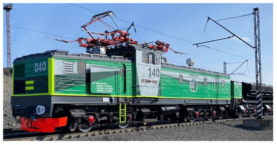
Figure 1.
OPE1AM traction unit №040 (photograph taken by the authors) [2].
A feature of electrified railway quarry transport is the change in routes and transport volumes depending on the degree of exploitation of the iron ore deposit and the volumes and methods of its extraction, while the end points of the routes are constantly moving away from the traction substations. As a result, situations are observed when the traction power supply system does not provide reliable and high-quality power to the electric rolling stock: in certain operating modes of the electric rolling stock, the actual voltage on the current receiver falls below the permissible regulatory level. In such situations, the train driver reduces the power of the electric rolling stock to actuate emergency protection, which leads to nonfulfillment of the movement schedule and disruption of the technological process. Strengthening the traction network or setting up additional traction substations is not considered appropriate due to significant capital costs. As a result, the throughput capacity of the track is limited, which negatively affects the operation of the mining complex.
Thus, the current state of electric traction systems for railway quarry transport does not meet the requirements for reduced energy consumption, decarbonization, or limiting production processes.
The authors see a solution to this problem in the application of a new electric rolling stock. In [3], a new electric locomotive was proposed for quarry railway transport. It considers the use of a traction asynchronous electric drive and an on-board energy storage system (ESS), the task of which is as follows:
- Energy accumulation during electrodynamic braking;
- Ensuring autonomous operation, including modes with low-quality energy consumption from the traction network;
- Power compensation in the case of low-quality traction power supply.
The accumulation of energy in the on-board ESS during electrodynamic braking is a key energy-saving technology used in rolling stock. The use of energy from the on-board ESS reduces the total energy consumption for movement.
One of the stages in electric locomotion is shunting on the tracks of the open top loading point when loading ore into dump trucks. To ensure the operation of the excavator that loads the ore, the contact wire is placed on the side of the track. At the same time, there is the possibility of touching this wire with the excavator bucket and, accordingly, the occurrence of a short circuit and damage to the traction network equipment. In the case of autonomous movement of the electric locomotive from the on-board ESS, the arrangement of the side contact wire is not required. The power consumed by the electric locomotive is not more than 10% of the rated power during shunting. This leads to the input converter’s mode with low energy indicators, in particular, the generation of higher harmonic components of the traction current in the traction network. Taking into account the fact that the open top loading point is at the end of the feeder zone, the flow of higher harmonic components of the traction current causes additional energy losses in the traction network.
As mentioned above, the traction network on the quarry railway does not provide regulatory voltage levels on the current receiver, which leads to a limitation in the power that can be transmitted by electric rolling stock. Therefore, it is rational to limit energy consumption from the traction network when the voltage on the current receiver drops below the permissible level, and perform power compensation from the on-board ESS.
The aim of this work is to determine the structure and parameters of the on-board ESS electric locomotive for quarry railway transport.
On-board ESS are created using supercapacitors [4,5], inertial energy storage [6,7], lithium batteries [8,9,10], and a combination of elements, mainly supercapacitors and lithium batteries [11,12,13]. The structure of the on-board ESS depends on the type of rolling stock [14,15]. Consequently, the problem arises in determining the rational parameters of the components, in particular the hybrid ESS, which consists of elements of different types [16]. For the most part, research is devoted to determining the parameters of ESS, which uses supercapacitors and lithium cells. In [17,18,19], the use of hybrid on-board ESS based on lithium batteries and supercapacitors was investigated and their advantages over ESS using only lithium batteries were shown. The use of supercapacitors allowed the peak power exchanged by the lithium battery to be reduced, decreasing its discharge, which positively affected the efficiency of the on-board ESS and extended the life of the lithium battery. In [20], a method is proposed to determine the parameters of an on-board ESS, which includes supercapacitors and lithium cells. The weight, size, and cost indicators were selected as optimization criteria. In [21], the parameters of the hybrid on-board ESS were determined to minimize the economic costs in terms of energy consumption and installation of the on-board ESS. This ensured a reduction in energy consumption by 25.59%. In [22], the optimal parameters of an on-board ESS with supercapacitors and lithium batteries were determined according to the criterion of the minimum cost of the elements. In [23], the application of hybrid on-board ESS on urban rail transport was studied. According to the results of calculations, it is shown that the use of ESS reduces losses in the traction network by 43%, decreases peak current by 32%, extends the battery life by 16.3%, and stabilizes the voltage of the traction network. In [24], a hybrid on-board ESS for an electric locomotive was investigated. In [25], the results of research on the on-board ESS of the tram provided parameters that were determined by taking into account the cost of elements and operating costs. The work described in [26] was devoted to improving the on-board ESS of the tram. Parameter optimization for the hybrid ESS and the application of energy management algorithms developed in the article show that the cost of daily operation is reduced by 25% compared to the ESS based on supercapacitors. In [27], a hybrid ESS with lithium cells of different types was investigated, as a result of which an increase in energy density of 5.56% and specific energy by 28.21% was achieved compared to ESS based on lithium cells of the same type. In [28], a hybrid ESS built with lithium nickel manganese cobalt oxides (NMC), elements with high specific energy, and lithium-titanium-oxide (LTO) elements with high specific power, was investigated. Depending on the optimization criterion, the hybrid ESS has up to 33.5% less weight or up to 30% less cost compared to the ESS built on elements of the same type. The work described in [29] was devoted to developing methodology for optimizing hybrid ESS with lithium cells of various types. It is shown that the use of a hybrid ESS allows for reducing costs compared to ESS on elements of the same type.
As can be seen from the analysis, the optimization of hybrid on-board ESS is widely used for vehicles of various purposes. When optimizing ESS, the parameters of its elements are determined primarily from the standpoint of minimizing the costs of its creation, acquisition, and the costs incurred during the operation of rolling stock. This approach reflects and takes into account the cost of the lifecycle as a criterion for choosing an on-board ESS option. However, its application requires information on the value of equipment, operating costs, maintenance, repair, etc. This causes difficulties in applying such an approach in the early stages of research.
An alternative approach to determining the optimal option is based on the application of complex criteria that combine technical parameters and economic indicators of the on-board ESS or the entire rolling stock. This approach is optimized using limited information on the cost characteristics of the electric locomotive’s electrical equipment. On this basis, we consider it appropriate to use just such an approach to optimize the on-board ESS of an electric locomotive for open-pit railway transport.
2. Research and Optimization of Hybrid On-Board Energy Storage System
2.1. Input Data
Figure 2 shows a version of the traction system structure for the electric locomotive under study. The intermediate circuit of the electric locomotive receives power from both the traction network and from the on-board ESS. This provides the possibility of a compatible and separate power supply from each of the energy sources of all connected consumers. The electric traction drive and auxiliary systems of the electric locomotive are connected to the intermediate circuit. The traction characteristics of the electric locomotive and the profile of the section from the crushing plant to the open top loading point of the route are shown in Figure 3 [3,30].
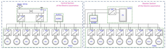
Figure 2.
Structural diagram of the traction system for the electric locomotive (P—pantograph, IC—input converter, TT—traction transformer, 4QS1, 4QS2—four-quadrant converters; AUXCS—auxiliary systems of electric locomotive control, ACM1—auxiliary converter module of the control section, ACM2—auxiliary converter module of booster section, OESS—energy storage system, ES—energy storage, MC—matching converter, TDCS—traction electric drive of the control section, TDBS—traction electric drive of the booster section, ТI1…ТI16—traction inverters, М1…М16—traction induction electric motors) [2].
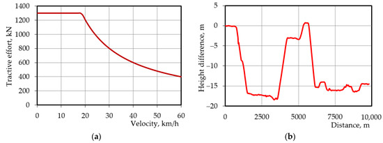
Figure 3.
Traction characteristics of the electric locomotive (a) and profile of the track section (b).
The determination of the parameters of the on-board ESS was carried out by analyzing the power dependence. Therefore, the method has found wide application for the study of ES systems [31,32,33]. The dependence of the power consumed by the electric drive and auxiliary systems from the intermediate circuit was used as the power dependence. This power was determined on calculations of the operating mode parameters of the traction electric drive and auxiliary systems.
When moving along a section of the path, the tangential power was determined when solving the traction problem. In general, this problem can be formulated as an optimization problem [34,35,36,37]. Furthermore, the electric traction drive of an electric locomotive is multimotor and, therefore, to increase its energy efficiency, it is recommended to use the load distribution between individual electric motors [38,39,40]. The empty half-passage, i.e., movement from the crushing plant to the open top loading point, is carried out by a train with 14 model 33-7141 dump trucks. The tare of the dump truck is 50 tons, the mass of the electric locomotive is 2 × 200 tons, and the electric locomotive moves forward. The path profile is shown in Figure 3b. The cargo half-passage is movement from the open-top loading point to the crushing plant, and is carried out with trucks each loaded with 115 tons of iron ore. Movement is carried out by wagons forward; the profile of the railway is the reverse of the profile for an empty half-passage. The traction task was solved using mathematical models given in [3,31,41,42,43], taking into account recommendations [44,45,46,47].
The methodology for determining the tangential power during shunting is described and carried out in [31]. The power for the auxiliary systems, first of all, motor fans for cooling traction motors, can also be optimized by taking into account the operating modes of the electric locomotive and its electric traction electric drive [48]. At this stage of the research, it is assumed that the power of the auxiliary systems does not depend on the mode of operation and is estimated by the authors to be 300 kW for the modes of movement along the path, 50 kW during shunting when loaded, and 100 kW during shunting when unloading.
The dependence of the tangential power for a full flight is shown in Figure 4.
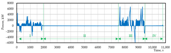
Figure 4.
Dependence of the tangential power on the electric locomotive (I—empty half-passage, II—shunting during loading, III—cargo half-passage, IV—shunting during unloading).
The calculation of the power consumed by the on-board ESS is determined in this paper based on the following considerations:
- In the electrodynamic braking mode, all available energy is accumulated in the energy storage (ES);
- In the traction mode, ES provides by power compensation when limiting its consumption from the traction network.
Taking into account the first condition, the power value is ES determined by using the formula:
where —nominal tangential power of the electric locomotive, equal to 6700 kW; —the efficiency of the traction electric drive (link “traction reducer–traction motor–traction inverter”) is taken as equal to 0.9; —the efficiency of the matching converter of ES, equal to 0.97.
For the electric locomotive, the ES power calculated by Equation (1) should not be less than 5850 kW.
As mentioned above, one of the functions of the on-board ESS is power compensation when limiting its consumption from the traction network. A system of a copper contact wire and a bimetallic carrier cable is used in the contact suspension on open-pit railway transport. The continuous current of the PBSM-95+MF-100 contact network (formed from a bimetallic wire of the PBSM-95 brand and a shaped copper wire of the MF-100 brand) is 660…820 A, depending on the degree of wear in the contact wire [49,50]. It is assumed that the maximum allowed current that can be consumed by one electric locomotive is 600 A. In open-pit railways electrified in an alternating current system, the lowest voltage in the pantographs is 7.5 kV. The power that can be consumed by an electric locomotive is determined by using the formula:
where —the minimum voltage on the current receiver is 7.5 kV; —the limit current consumed by the electric locomotive from the catenary network (equal to 600 A); —the power factor of the electric locomotive is equal to 0.98 for traction modes. Then, the power calculated by Equation (2) is approximately 4400 kW.
To ensure the compensation mode, the power of the energy storage is determined by using the formula:
where —the power consumed by the auxiliary systems of the electric locomotive in traction mode; —the efficiency of the input converter (link “traction transformer—4qs-converter”) is 0.95.
The minimum power calculated by Equation (3) is ES 3575 kW. It should be noted that determining the value of ES power when limiting power consumption from the traction network requires detailed research and is not the purpose of this work.
The power exchanged by the on-board ESS with the intermediate circuit is determined by using the formula:
where —the power that is consumed or delivered in the intermediate circuit, which is determined by the equation:
It is assumed here that in the electrodynamic feeding mode of auxiliary systems provided by the traction electric drive, the power is always sufficient.
The change in ES energy during the i-th stage of ES charging or discharging is:
where —duration of the i-th stage; —dependence of power ES on time during the i-th stage; —storage efficiency equal to 0.98
Figure 5 shows the dependence of the power exchanged between the on-board ESS with the intermediate circuit and the change in the ES energy at an initial energy of 102 kWh.
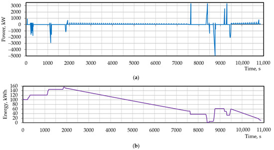
Figure 5.
Dependencies of the power exchanged by the on-board ESS with the intermediate circuit (a) and energy of the ES (b).
The dependencies analysis in Figure 5 confirms that discharge of the ES occurs in modes when there are restrictions on the power consumption from the traction network and during shunting. Charging of the ES occurs in electrodynamic braking modes during service braking to maintain speed during braking before stopping. When discharging, the maximum power taken from the on-board ESS is about 3400 kW, and when charging it reaches 5000 kW. The operating energy capacity of the ES is defined as the difference between the maximum and minimum value depending on the energy change in the ES and is about 150 kWh.
2.2. Research On-Board ESS with Elements of the Same Type
The calculation of the parameters of the on-board ESS is provided below. Consider the following cases: (1) only LTO elements are used in the on-board ESS; (2) only lithium iron-phosphate (LFP) elements are used in the on-board ESS; and (3) supercapacitors are used in the on-board ESS. For example, consider YINLONG 66160H 2.3v 40ah LTO cells (Gree Altairnano New Energy Inc., Zhuhai, China) [51], ENERpower 26650 LiFePO4 3.2V 3000mAh (10C) LFP cells (Heter Electronics Group Co., Ltd, Shenzhen, China) [52], and Maxwell 3000 FARAD Capacitor Boostcap 3000f 2.7volt BCAP3000 supercapacitors (Maxwell Technologies Korea Co., Ltd, Yongin-si, South Korea) [53]. Table 1 shows the technical parameters for the elements based on information from the manufacturers’ websites. The cost of the elements is taken from online marketplaces.

Table 1.
Parameters of storage elements.
The parameters of the on-board ESS were calculated according to the following model, developed taking into account the recommendations [28,29,54,55,56].
The capacity of the on-board ESS is determined by using the formula:
where —working energy capacity; —coefficient that takes into account the decrease in the capacity of the ES during the period of operation assumed equal to 0.9; —coefficient, which takes into account the decrease in the capacity of the ES when the temperature changes, self-discharge, etc., we accept 0.95; SOC—the stage of charge.
The value of SOC1 should be selected to ensure maximum ES with maximum power. Usually for lithium cells SOC1 = 90%, for a supercapacitor—100%. The value of SOC2 should be selected at the permissible discharge level of the ESS. Usually SOC2 = 10% for lithium cells, 0% for supercapacitors.
If necessary, other factors can be taken into account in Equation (7), leading to a decrease in capacity.
Let elements be used in the on-board ESS, which is characterized by the following technical parameters. The number of serially connected elements is determined by the expression:
where —intermediate circuit voltage; —voltage at the end of charging the element. The resulting value is rounded up.
The number of parallel branches is determined by using the formula:
where —the number of parallel branches is determined from the condition “by energy”;—the number of parallel branches is determined from the condition “by power”.
The number of parallel branches is determined from the condition “by energy” and defined by using the formula:
where —capacity of one element, expressed in kWh; —coefficient which takes into account the decrease in energy that can be stored by the ES element when charging with a current that exceeds the optimal value (assumed equal to 0.9). The resulting value is rounded up.
The number of parallel branches determined from the condition “by power” is defined by using the formula:
where —rated power of ES; —element discharge voltage; —the smaller the charge and discharge currents of the element . Here, —permissible charging current, —permissible discharge current. The resulting value is rounded up. The number of elements:
The total mass of elements of the on-board ESS:
where —the mass of one element.
The volume which is necessary for the placement of elements of the on-board ESS:
where ,,—length, width, and height of the prismatic element, respectively. For a cylindrical element, the length and width are assumed to be equal to the diameter .
The cost of elements of on-board ESS:
where —the cost of one element.
The total capacity of elements of the on-board ESS:
where —energy capacity of one element.
The results of the calculations are given in Table 2.
Table 2.
Calculation results.
The model for calculating the ES parameters (Equations (7)–(16)) does not take into account design features such as the cooling system or the dimensions of the battery management system (BMS). The determination of their parameters requires a detailed constructive processing of the elements of the ESS, which is not part of this research task.
As we can see from Table 2, the largest mass-dimensional ESS is based on LFP-elements. ES with supercapacitors is the smallest mass-dimensional, ES with LTO cells has the smallest volume required for the placement. The lowest cost of cells is also in the case of ES with LTO cells.
The total energy capacity of cells for ES with supercapacitors is almost equal to the energy capacity of ES. The total energy capacity of ES cells with LTO elements exceeds the required by 5.5 times and, in the case of LFP elements, by 14.7. On the one hand, such an excess allows recharge ES through several passages, and on the other hand, the “excess” energy capacity leads to an increase in the mass and dimensions of ES as well as capital costs for acquisition. The lowest cost is ES based on LTO elements. The lowest cost per kWh is ES based on LFP elements.
So, by mass criteria, volume, cost, and the cost of one kilowatt-hour, none of the ES options based on the same type of elements simultaneously provides minimum indicators for all criteria. In such cases, multicriteria optimization is used to select a rational option.
2.3. Optimization of Hybrid ES
Optimization of weight, dimensions, and cost indicators is widely used in the optimization of on-board ESS vehicles for various purposes [23,57,58,59,60,61]. Such problems belong to the class of multicriteria optimization problems [62,63,64].
The conditional optimization problem is formulated in the form:
with restrictions in the form of equalities and the form of inequalities . , where —objective function, —vector of varied parameters, and —vectors of the lower and upper bounds of the varied parameters.
A common method of optimization is to use different types of elements in ES, most often lithium cells and supercapacitors or lithium cells of various types. It follows from the above that ES is necessary to optimize simultaneously by several criteria, which describe different properties. In this case, we apply the additive criterion composed of partial criteria that are accepted as the mass of elements ES, the volume necessary for their placement, and the cost of elements. The choice of the mass and volume of elements as criteria is explained by the fact that the corresponding parameters of the entire onboard energy storage system, which includes temperature stabilization systems, mounting elements, etc., depend on them. The relationship between the parameters is proportional: the smaller the mass and volume of the elements, the smaller the mass and volume of the entire energy storage device. Accordingly, a decrease in the mass and volume of elements leads to a decrease in these parameters for the entire energy storage device. Reducing the cost of elements reduces the capital investment in its creation, which makes the drive more attractive.
Additive convolution of criteria [60,61] was used for calculations. To bring it to a dimensionless form, the criteria are normalized. For this, the largest and smallest values of the criteria were used for the case when the energy storage uses elements of the same type. Since the value of the objective function is affected by a set of weighting factors set by the researcher, it is appropriate to study the influence of a set of weighting factors on the result.
The objective function has the form (fractions are introduced into the objective function to normalize the variables):
where —the total mass of the elements of ES, (—the mass of elements of the first and second type, respectively); —the largest and smallest mass of ES elements from
which the hybrid ES is “mixed”; —the
total volume of elements of ES (—the volume of elements of the first and second type, respectively); —the largest and smallest volume which is necessary for placement of elements ES from which the hybrid ES is “mixed”; —the total cost of the elements of ES, (—the cost of elements of the first and second type, respectively); —the largest and smallest cost of the elements of ES, from which the hybrid ES is “mixed”; —weighting factors
As a variable in the objective function (Equation (18)), we take the power of the ES part which is formed by “energy” elements. For calculations, we impose restrictions. The left border is selected from the condition of ensuring the autonomous movement of the electric locomotive during shunting, the right border is the highest power, which is ES exchanged by the intermediate circuit of the traction system.
The hybrid ES consists of two conventional parts—“energy” and “power”. Algorithms for calculating power dependences of these parts, necessary for calculating energy storage parameters according to Equations (7)–(16), are necessary for calculating the objective function and given below.
Calculation of power dependence, which is consumed from the “energy” part is performed according to the following equations:
- The instantaneous power of the “energy” part of ES is determined:
- The power of the “power” part of ES is determined:
In Equations (19) and (20), the ES discharge meets the condition , charging—.
ES energy is defined as follows. The ES energy at the r-th stage of charging is determined by using the formula:
where —dependence of the power transferred to the ES at the r-th stage of charging; —the energy of ES at the beginning of the r-th stage of charging.
The ES energy at the p-th stage of charging is determined by using the formula:
where —power dependence which ES is consumed at the p-th discharge stage; —ES energy at the beginning of the p-th discharge stage.
Equations (21) and (22) are applied as both parts of the ES.
The algorithm for calculating the objective function is as follows:
Set the power of the “energy” part of the ES:
- Calculate power dependences for the “energy” and “power” parts according to Equations (19) and (20), respectively;
- Calculate the energy dependence of the “energy” and “power” parts using Equations (21) and (22);
- Calculate ES parameters for the “energy” and “power” parts according to the model Equations (7)–(16);
- Specify a set of weighting coefficients and calculate the value of the objective function (18).
Consider three options for ES hybridization: (1) the “power part” is formed by LTO elements: “powerful”—supercapacitors; (2) “energy part” is formed by LFP-elements: “powerful”—supercapacitors; (3) “energy part” is formed by LFP-elements: “powerful”—with LTO elements.
Since the result of the objective function depends on the set of weighting factors, several cases are considered. The objective function (18) is a function of one variable, which allows building it graphically and determining the minimum value from the graph. Figure 6 shows the dependence of the objective function on the power of the “energetic” part of the ES with different sets of weighting coefficients.
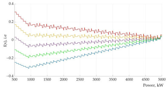
Figure 6.
Dependence of the objective function on power (the red line is the objective function with coefficients ; the yellow line is the objective function with coefficients ; the purple line is the objective function with coefficients ; the green line is the objective function with coefficients ; and the blue line is the objective function with coefficients ).
To determine the minimum of the objective function, its calculations were carried out with a change in power, after which the minimum value was determined. One-dimensional optimization algorithms were not used.
The results for the optimal point calculation are shown in Table 3.
Table 3.
Results of calculations of ES parameters with LTO elements and supercapacitors.
As can be seen in Table 3, the optimum of the objective function depends on the set of weighting coefficients. In particular, the decision is influenced by the weighting coefficients for terms that take into account mass and volume. However, we have two variants of optimal power—4740 and 920 kW. Table 4 shows a comparison of the ES parameters based on LTO elements and hybrid ES.
Table 4.
Comparison of options.
As can be seen in Table 4, the variant of the hybrid ES with the power of the “energy” part of 4740 kW is practically no different from the basic ES. In the hybrid ES with the power of the “energy” part of 920 kW, the weight of the ES decreases from 16.8 to 12.2 t (1.38 times) with a slight increase in volume from 9.6 to 10.6 m3 (1.1 times). The cost of elements for this option is reduced from 1101.7 thousand EUR to 1002.24 thousand EUR (1.1 times). However, the storage capacity decreases from 1172 to 328.9 kWh (3.56 times), and the cost of “one kilowatt-hour” increases from 0.94 thousand EUR to 3.05 thousand EUR—3.2 times. In other words, with practically the same cost for elements, in the case of a hybrid ES, we obtain a capacity 3.2 times smaller than in the case of ES only on LTO cells. Table 5 and Table 6 show the calculation results for the variant of the hybrid ES with LFP elements and supercapacitors and the variant of the hybrid ES with LFP elements in the “energy part” and LTO elements. The results of the calculations showed that the optimal power for such ES does not depend on the set of weighting factors and is 500 kW for LFP + SC and 520 kW for LFP + LTO.
Table 5.
Results of calculations of ES parameters with LFP elements and supercapacitors.
Table 6.
Results of calculations of ES parameters with LFP- and LTO elements.
As can be seen in Table 5 and Table 6, the hybridization of the LFP accumulator allows for a reduction in its mass by 2.22 times and its volume by 1.3 times. The cost of elements is reduced by 1.24 times. However, the energy intensity of the elements decreases by 7.06. and the cost of “one kilowatt-hour” increases by 5.63 times. That is, the situation is similar to the case of the hybrid ES based on LTO elements and supercapacitors (SC). Optimization allows for significantly improved mass-dimensional indicators. However, it does not reduce energy consumption.
So hybridization does not allow for the improvement in the mass and dimensional indicators; however, it leads to a significant reduction in the energy capacity of ES. At the same time, the cost of the ES elements decreases significantly. As a result, it leads to a high cost of one kilowatt-hour of ES capacity.
One of the criteria for considering the cost of energy storage elements is the cost of one kilowatt-hour of energy. Consider a calculation for this case. As in the previous case, normalization criteria and additive convolution were applied. The influence of weighting factors on the result of the calculation of the objective function was also investigated.
The objective function for this case can be given as:
where —the cost of one kWh of element capacity. (—the energy capacity of the parts of ES).
The algorithm for calculating the values of the objective function is given above. Hybridization options are the same as in the previous study.
Table 7 shows the calculation results for the option of LTO elements in the “energy” part, and supercapacitors in the “power” part of ES. Figure 7 shows the dependence of the objective function on different weighting factors for this option.
Table 7.
Results of calculations of ES parameters.
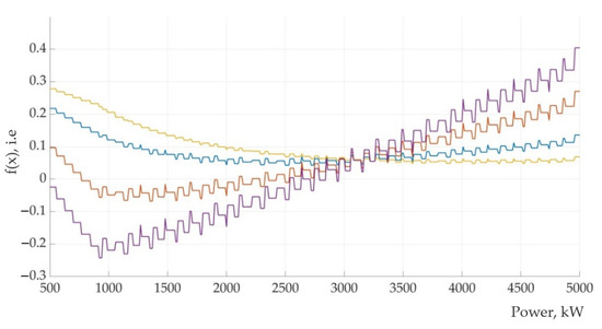
Figure 7.
Dependence of the objective function (the yellow line is the objective function with coefficients ; the blue line is the objective function with coefficients ; the red line is the objective function with coefficients ; and the purple line is the objective function with coefficients ).
As can be seen in Table 7 and Figure 7, the optimal power when hybridizing depends on the set of weighting factors. In general, the situation is similar to the one discussed above. With the improvement in the mass indicators, the energy capacity of the storage device decreases and the cost of one kilowatt-hour increases.
Table 8 and Table 9 show the results of the parameters of ES with the hybridization of LFP + SC and LFP + LTO.
Table 8.
Results of calculations of ES parameters with hybridization of LFP elements and supercapacitors.
Table 9.
Results of calculations of ES parameters with hybridization LFP- and LTO elements.
The results of the calculations for the variant with LFP cells and supercapacitors are similar to the results for the variant with LTO cells and supercapacitors. For the variant with LFP and LTO-elements, the fact attracts attention: the optimal power does not depend on the set of weighting factors. Furthermore, the parameters of such a hybrid ES are close to the ES parameters on LTO cells.
Therefore, in the cases studied, hybridization did not provide, first of the all, a reduction in the mass of elements, and in some cases a reduction in volume is necessary to place the elements. At the same time, during hybridization, the energy intensity of the elements can significantly decrease with a slight decrease in the cost.
3. Discussion
This paper investigates a procedure for selecting energy storage parameters for the on-board ESS of a mining electric locomotive. For the calculations, it is proposed to use the dependence of the tangential power of the electric locomotive and the power of the auxiliary systems based on which the power dependence was calculated. A feature of the ES for the electric locomotive under study is the need for power compensation for the electric locomotive traction system in the case when the capacity of the traction network is limited. Another aspect is the need to power the electric locomotive’s systems during autonomous shunting movement. Together, these features lead to the need for the creation of an ES with a capacity of 4950 kW and an operating energy capacity of 150 kWh to ensure the operation of the electric locomotive according to the selected algorithm.
LTO elements, LFP elements, and supercapacitors are selected for parameter evaluation. The calculation of parameters is shown. Their mass can be 14.9…28.7 tons, and the volume to place the elements is 9.6…14.5 m3. Such mass-dimensional indicators can cause difficulties with the placement of ES on an electric locomotive. Therefore, it is advisable to improve it. This is possible with the hybridization of ES when elements of different types are used. The conducted studies show that the possible reduction in the mass of the ES to 12.8 tons is 1.16…2.24 times, depending on the basic version of the ES. At the same time, the volume increases by 1.1 times, which can be considered acceptable. However, during hybridization, the energy intensity of ES is significantly reduced, but even with a sufficiently significant reduction in the cost of the elements, it does not lead to an increase in the cost of a kilowatt-hour. This reduces the attractiveness of capital investments in such an ESS for the electric locomotive under study. Therefore, we consider the option based on LTO elements to be acceptable, which can be considered a tradeoff for the selected evaluation criteria. A reduction in weight and dimensions is observed when using LTO elements with other technical parameters. The study of this issue is not considered in this article.
4. Conclusions
The article considers the application of an on-board energy storage system for an electric locomotive for quarry railway transport. The features of its operation include power compensation while limiting its consumption from the traction network, energy accumulation during electrodynamic braking, and power supply of electric locomotive systems during autonomous shunting operation.
The method of determining the parameters of the on-board ESS was proposed and its indicators were investigated when using LTO elements, LFP elements, and supercapacitors. The hybridization of ES was studied when such elements were taken into account. According to the results of the calculations, it is established that during hybridization, the mass of ES significantly decreases. At the same time, during hybridization, the energy intensity of the ES is significantly reduced, and as a result, the cost of a kilowatt-hour of ES increases. This reduces the efficiency of capital investments in such an ESS. Therefore, we consider it expedient to use ES based on LTO elements. The improvement of which indicators is possible through the selection of elements. An alternative option may be a hybrid ES based on LTO and LFP elements.
Author Contributions
Conceptualization, I.R. and L.K.; methodology, S.G.; software, I.R.; validation, S.G., I.R. and L.K.; formal analysis, S.G., I.R. and L.K.; resources, V.L., A.K. and R.M.; data curation, V.L., A.K. and R.M.; writing—original draft preparation, S.G., I.R. and L.K.; writing—review and editing, V.L., A.K. and R.M; visualization, I.R. and V.L.; supervision, S.G.; project administration, S.G.; funding acquisition, V.L., A.K. and R.M. All authors have read and agreed to the published version of the manuscript.
Funding
This research received no external funding.
Data Availability Statement
Not applicable.
Conflicts of Interest
The authors declare no conflict of interest.
References
- A European Green Deal. Available online: https://commission.europa.eu/strategy-and-policy/priorities-2019-2024/european-green-deal_en (accessed on 1 March 2022).
- Kondratieva, L.; Bogdanovs, A.; Overianova, L.; Riabov, I.; Goolak, S. Determination of the working energy capacity of the on-board energy storage system of an electric locomotive for quarry railway transport during working with a limitation of consumed power. Arch. Transp. 2023, 65, 119–135. [Google Scholar] [CrossRef]
- Riabov, I.; Mosin, S.; Overianova, L.; Kondratieva, L.; Demydov, O.; Goolak, S. Otsinka tekhnichnykh parametriv lokomotyva dlia zaliznychnoho kariernoho transportu (Evaluation of technical parameters locomotive for railway career transport). Transp. Syst. Technol. 2022, 39, 83–100. (In Ukrainian) [Google Scholar] [CrossRef]
- Steiner, M.; Klohr, M.; Pagiela, S. Energy storage system with ultracaps on board of railway vehicles. In Proceedings of the European Conference on Power Electronics and Applications, Aalborg, Denmark, 2–5 September 2007; pp. 1–10. [Google Scholar] [CrossRef]
- Reynaud, J.F.; Garmendia, M.; Nieva, T. Comprehensive integration of Onboard Energy Storage systems in tramways: Birmingham tram case study. In Proceedings of the 2018 IEEE International Conference on Electrical Systems for Aircraft, Railway, Ship Propulsion and Road Vehicles and International Transportation Electrification Conference ESARS-ITEC 2018, Nottingham, UK, 7–9 November 2018; pp. 1–6. [Google Scholar]
- Masamichi, O. Application of Energy Storage Technologies for Electric Railway Vehicles—Examples with Hybrid Electric Railway Vehicles. IEEJ Trans. Electr. Electron. Eng. 2010, 5, 304–311. [Google Scholar]
- Lenhard, D.; Engel, B.; Langwost, J.; Söffker, C. Elektrische Ausrüstung des Triebzüges LIREX Baureihe 618/619 für DB Regio. Elektr. Bahnen 2000, 8, 279–289. [Google Scholar]
- Kono, Y.; Shiraki, N.; Yokoyama, H.; Furuta, R. Catenary and storage battery hybrid system for electric railcar series EV-E301. In Proceedings of the 2014 International Power Electronics Conference, IPEC-Hiroshima-ECCE Asia 2014, Hiroshima, Japan, 18–21 May 2014; pp. 2120–2125. [Google Scholar]
- Becker, F.; Dammig, A. Catenary free operation of light rail vehicles—Topology and operational concept. In Proceedings of the 2016 18th European Conference on Power Electronics and Applications, EPE 2016 ECCE Europe, Karlsruhe, Germany, 5–9 September 2016; pp. 1–10. [Google Scholar]
- Rufer, A.C. Energy storage for railway systems, energy recovery and vehicle autonomy in Europe. In Proceedings of the 2010 International Power Electronics Conference-ECCE ASIA-, Sapporo, Japan, 21–24 June 2010; Volume 1, pp. 3124–3127. [Google Scholar]
- Manning, T.; van der Steen, A. Overview of Hydrogen and Fuel Cell Developments in China. Holland Innovation Network, Shangai. Available online: https://www.nederlandwereldwijd.nl/binaries/nederlandwereldwijd/documenten/publicaties/2019/03/01/waterstof-in-china/Holland+Innovation+Network+in+China+-+Hydrogen+developments.+Juary+2019.pdf (accessed on 1 March 2022).
- Liu, Z.X.; Chen, W.; Zhang, X. Fuel cell based hybrid power system design for a passenger tram. In Proceedings of the WHEC 2016-21st World Hydrogen Energy Conference 2016, Zaragoza, Spain, 13–16 June 2016; Volume 51, pp. 1119–1121. [Google Scholar]
- Lemian, D.; Bode, F. Battery-Supercapacitor Energy Storage Systems for Electrical Vehicles: A Review. Energies 2022, 15, 5683. [Google Scholar] [CrossRef]
- Zhang, B.; Lu, S.; Peng, Y.; Wu, C.; Meng, G.; Feng, M.; Liu, B. Impact of On-Board Hybrid Energy Storage Devices on Energy-Saving Operation for Electric Trains in DC Railway Systems. Batteries 2022, 8, 167. [Google Scholar] [CrossRef]
- Fedele, E.; Iannuzzi, D.; del Pizzo, A. Onboard energy storage in rail transport: Review of real applications and techno-economic assessments. IET Electr. Syst. Transp 2021, 11, 279–309. [Google Scholar] [CrossRef]
- Ostadi, A.; Kazerani, M. A Comparative Analysis of Optimal Sizing of Battery-Only, Ultracapacitor-Only, and Battery–Ultracapacitor Hybrid Energy Storage Systems for a City Bus. IEEE Trans. Veh. Technol. 2015, 64, 4449–4460. [Google Scholar] [CrossRef]
- Arefin, M.A.; Mallik, A. Hybridization of battery and ultracapacitor for low weight electric vehicle. J. Mech. Energy Eng. 2018, 2, 43–50. [Google Scholar] [CrossRef]
- Zheng, C.; Wang, Y.; Liu, Z.; Sun, T.; Kim, N.; Jeong, J.; Cha, S.V. A Hybrid Energy Storage System for an Electric Vehicle and Its Effectiveness Validation. Int. J. Precis. Eng. and Manuf.-Green Tech. 2021, 8, 1739–1754. [Google Scholar] [CrossRef]
- Sadeq, T.; Wai, C.K.; Morris, E.; Tarbosh, Q.A.; Aydoğdu, Ö. Optimal Control Strategy to Maximize the Performance of Hybrid Energy Storage System for Electric Vehicle Considering Topography Information. IEEE Access 2020, 8, 216994–217007. [Google Scholar] [CrossRef]
- Liu, F.; Wang, C.; Luo, Y. Parameter Matching Method of a Battery-Supercapacitor Hybrid Energy Storage System for Electric. Vehicles. World Electr. Veh. J. 2021, 12, 253. [Google Scholar] [CrossRef]
- Zhang, B.; Wu, C.; Meng, G.; Xue, F.; Lu, S. Optimal Sizing of Onboard Hybrid Energy Storage Devices Considering the Long-Term Train Operation. IEEE Access 2022, 10, 58360–58374. [Google Scholar] [CrossRef]
- Piriienko, S.; Balakhontsev, A.; Beshta, A.; Albu, A.; Khudoliy, S. Optimization of hybrid energy storage system for electric vehicles. Power Electron. Drives 2016, 1, 97–111. [Google Scholar] [CrossRef]
- Graber, G.; Galdi, V.; Calderaro, V.; Piccolo, A. Sizing and energy management of on-board hybrid energy storage systems in urban rail transit. In Proceedings of the 2016 International Conference on Electrical Systems for Aircraft, Railway, Ship Propulsion and Road Vehicles & International Transportation Electrification Conference (ESARS-ITEC), Toulouse, France, 2–4 November 2016; pp. 1–6. [Google Scholar] [CrossRef]
- Wongthong, Y.; Rattanapanyalert, T.; Supopat, T.; Techawatcharapaikul, C. A Design of Energy Storage System for Electric Locomotive. In Proceedings of the 2021 9th International Electrical Engineering Congress (iEECON), Pattaya, Thailand, 10–12 March 2021; pp. 149–152. [Google Scholar] [CrossRef]
- Jia, L.; Qin, Y.; Liu, B.; Liu, Z.; Diao, L.; An, M. (Eds.) Proceedings of the 4th International Conference on Electrical and Information Technologies for Rail Transportation (EITRT) 2019. In Lecture Notes in Electrical Engineering; Springer: Berlin/Heidelberg, Germany, 2020; Volume 638. [Google Scholar] [CrossRef]
- Herrera, V.; Milo, A.; Gaztaga, H.; Etxeberria-Otadui, I.; Villarreal, I.; Camblong, H. Adaptive energy management strategy and optimal sizing applied on a battery-supercapacitor based tramway. Appl. Energy 2016, 169, 831–845. [Google Scholar] [CrossRef]
- Avila, A.; Lucu, M.; Garcia-Bediaga, A.; Ibarguren, U.; Gandiaga, I.; Rujas, A. Hybrid Energy Storage System Based on Li-Ion and Li-S Battery Modules and GaN-Based DC-DC Converter. IEEE Access 2021, 9, 132342–132353. [Google Scholar] [CrossRef]
- Akbarzadeh, M.; De Smet, J.; Stuyts, J. Battery Hybrid Energy Storage Systems for Full-Electric Marine Applications. Processes 2022, 10, 2418. [Google Scholar] [CrossRef]
- Becker, J.; Nemeth, T.; Wegmann, R.; Sauer, D.U. Dimensioning and Optimization of Hybrid Li-Ion Battery Systems for EVs. World Electr. Veh. J. 2018, 9, 19. [Google Scholar] [CrossRef]
- Riabov, I.; Kondratieva, L.; Overianova, L.; Goolak, S. Assessment of the On-Board Energy Storage Parameters of the Locomotive for Rail Quarry Transport. In Lecture Notes in Intelligent Transportation and Infrastructure; Prentkovskis, O., Yatskiv, I., Skačkauskas, P., Maruschak, P., Karpenko, M., Eds.; Springer: Cham, Switzerland, 2022. [Google Scholar] [CrossRef]
- Riabov, Y.S.; Kondratieva, L.Y.; Overianova, L.V.; Yeritsyan, B.K.; Hulak, S.O. Justification of the Structure of the Electric Traction Drive of the Electric Locomotive for Railway Quarry Transport. Sci. Transp. Prog. 2022, 2, 26–44. [Google Scholar] [CrossRef]
- Ryalko, A.; Dybrin, S. Vybor emkosty nakopytelia enerhyy dlia obespechenyia snyzhenyia maksymuma potrebliaemoi moshchnosty (Selection of energy storage capacity to ensure reduction of the maximum power consumption). Min. Inf. Anal. Bull. 2008, 8, 356–361. (In Russian) [Google Scholar]
- Omelyanenko, V.I.; Riabov, I.S.; Overianova, L.V.; Omelianenko, H.V. Traction electric drive based on fuel cell batteries and on-board inertial energy storage for multi unit train. Electr. Eng. Electromechanics 2021, 4, 64–72. [Google Scholar] [CrossRef]
- Petrenko, O.; Liubarskiy, B.; Pliugin, V. Determination of railway rolling stock optimal movement modes. Electr. Eng. Electromechanics 2017, 6, 27–31. [Google Scholar] [CrossRef]
- Yinping, F.; Ziyou, G.; Keping, L. Optimization Method of Energy Saving Train Operation for Railway Network. J. Transp. Syst. Eng. Inf. Technol. 2009, 9, 90–96. [Google Scholar] [CrossRef]
- Wu, C.; Zhang, W.; Lu, S.; Tan, Z.; Xue, F.; Yang, J. Train Speed Trajectory Optimization with On-Board Energy Storage Device. IEEE Trans. Intell. Transp. Syst. 2019, 20, 4092–4102. [Google Scholar] [CrossRef]
- Liu, J.; Cai, B.-G.; Xu, G.; Sun, G.-F. Energy Consumption Modeling and Optimization of Traction Control for High-speed Railway Trains. Int. J. Control Autom. 2015, 8, 109–124. [Google Scholar] [CrossRef]
- Voytenko, V.A.; Vodichev, V.A.; Kalinin, A.G. Analysis of Technical and Energy Indicators of a Multi-Motor Electric Drive for Urban Public Transport. Probl. Energeticii Reg. 2019, 1–2, 95–106. [Google Scholar] [CrossRef]
- Nezamuddin, O.; Bagwe, R.; Dos Santos, E. A Multi-Motor Architecture for Electric Vehicles. In Proceedings of the 2019 IEEE Transportation Electrification Conference and Expo (ITEC), Detroit, MI, USA, 19–21 June 2019; pp. 1–6. [Google Scholar] [CrossRef]
- Xu, S.; Wei, L.; Zhang, X.; Bai, Z.; Jiao, Y. Research on Multi-Mode Drive Optimization Control Strategy of Four-Wheel-Drive Electric Vehicles with Multiple Motors. Sustainability 2022, 14, 7378. [Google Scholar] [CrossRef]
- Riabov, I.; Liubarskyi, B.; Overianova, L.; Goolak, S.; Kondratieva, L. Mathematical Model of the Electric Traction System of Quarry Railway Transport. In Proceedings of the 26th International Scientific Conference, Transport Means, 5–7 October 2022; pp. 330–335. [Google Scholar]
- Goolak, S.; Liubarskyi, B.; Sapronova, S.; Tkachenko, V.; Riabov, I. Refined Model of Asynchronous Traction Electric Motor of Electric Locomotive. In Proceedings of the 25th International Scientific Conference Transport Means, Online, 6–8 October 2021; pp. 455–460. [Google Scholar]
- Goolak, S.; Riabov, I.; Gorobchenko, O.; Yurchenko, V.; Nezlina, O. Improvement of the model of an asynchronous traction motor of an electric locomotive by taking into account power losses. Prz. Elektrotechniczny 2022, 98, 1–10. [Google Scholar] [CrossRef]
- Sapronova, S.Y.; Tkachenko, V.P.; Fomin, O.V.; Kulbovskiy, I.I.; Zub, E.P. Rail Vehicles: The Resistance to the Movement and the Controllability: Monograph; Ukrmetalurginform STA: Dnipro, Ukraine, 2017; 160p. [Google Scholar]
- Balon, L.V.; Bratash, V.A.; Buchich, M.L.; Kuzmenko, L.A.; Pacovskyi, J.V.; Choruzhyi, A.S.; Shavykin, V.J. Elektropodvyzhnoi Sostav Promyshlennoho Transporta: Spravochnyk (Electromotive Equipment of Industrial Transport: Reference Book); Balon, L.V., Ed.; Transport: Moscow, Russia, 1987; 296p. (In Russian) [Google Scholar]
- Kuznetsov, V.; Kardas-Cinal, E.; Gołębiowski, P.; Liubarskyi, B.; Gasanov, M.; Riabov, I.; Kondratieva, L.; Opala, M. Method of Selecting Energy-Efficient Parameters of an Electric Asynchronous Traction Motor for Diesel Shunting Locomotives—Case Study on the Example of a Locomotive Series ChME3 (ЧMЭ3, ČME3, ČKD S200). Energies 2022, 15, 317. [Google Scholar] [CrossRef]
- Kuznetsov, V.; Liubarskyi, B.; Kardas-Cinal, E.; Yeritsyan, B.; Riabov, I.; Rubanik, I. Recommendations for the selection of parameters for shunting locomotives. Arch. Transp. 2020, 5, 119–133. [Google Scholar] [CrossRef]
- Liubarskyi, B.; Petrenko, O.; Iakunin, D.; Dubinina, O.O. Optimization of thermal modes and cooling systems of the induction traction engines of trams. East.-Eur. J. Enterp. Technol. 2017, 3, 59–67. [Google Scholar] [CrossRef]
- Frolov, O.O.; Kosenko, T.V. Vidkryti hirnychi roboty: Ch. I. Protsesy Vidkrytykh Hirnychykh Robit [Elektronnyi Resurs]: Navch. Posib. Dlia Stud. spetsialnosti 184 «Hirnytstvo»/(Open Pit Mining: Part I. Processes of Open Pit Mining [Electronic Resource]: Education. Manual for Students Specialty 184 “Mining”)/;KPI Named after Igor Sikorsky. Available online: https://ela.kpi.ua/bitstream/123456789/34701/1/Vidkryti_girnychi_roboty.pdf (accessed on 1 March 2022).
- Dryzhenko, A.Y. Vidkryti Hirnychi Roboty; Open Pit Mining; NHU: Dnipro, Ukraine, 2014. (In Ukrainian) [Google Scholar]
- Yinlong Battery Technology. Available online: https://www.yinlong.energy/yinlong-battery#footer (accessed on 1 March 2022).
- ENERpower 26650 LiFePO4 3.2V 3000mAh (10C). Available online: https://enerprof.de/en/lifepo4-batteries/lifepo4-battery-cells/lifepo4-battery-cells-26650/36/enerpower-26650-lifepo4-3.2v-3300mah-10c (accessed on 1 March 2022).
- Maxwell’s High Power and Energy Cell. Data Sheet. Available online: https://maxwell.com/wp-content/uploads/2021/09/3003279.2_Final-DS_New-2.7V-3000F-Cell_20210406.pdf (accessed on 1 March 2022).
- Mezitis, M.; Panchenko, V.; Yatsko, S.; Vashchenko, Y.; Sidorenko, A.; Sansyzbajeva, Z. Selection of mathematical model of on-board capacity energy storage as element of hybrid traction unit of motor car rolling stock. J. Meas. Eng. 2021, 9, 71–86. [Google Scholar] [CrossRef]
- Buryakovskiy, S.; Maslii, A.; Pomazan, D.; Maslii, A.; Panchuk, O.; Rybin, A. Study of Methods for Charging of Energy Storage Devices of Railway Traction Units. In Proceedings of the 2020 IEEE Problems of Automated Electrodrive. Theory and Practice (PAEP), Kremenchuk, Ukraine, 21–25 September 2020; pp. 1–5. [Google Scholar] [CrossRef]
- Degaa, L.; Rizoug, N.; Bendjedia, B.; Saidane, A.; Larouci, C. Sizing improvement of hybrid storage system composed with high energy and high power Li-ion batteries for automotive applications. J. Syst. Control Eng. 2019, 233, 870–876. [Google Scholar] [CrossRef]
- Prasanthi, A.; Shareef, H.; Asna, M.; Ibrahim, A.; Errouissi, R. Optimization of hybrid energy systems and adaptive energy management for hybrid electric vehicles. Energy Convers. Manag. 2021, 243, 114357. [Google Scholar] [CrossRef]
- Wu, C.; Lu, S.; Xue, F.; Jiang, L.; Chen, M. Optimal Sizing of Onboard Energy Storage Devices for Electrified Railway Systems. IEEE Trans. Transp. Electrif. 2020, 6, 1301–1311. [Google Scholar] [CrossRef]
- De la Torre, S.; Sanchez-Racero, A.J.; Aguado, J.A.; Reyes, M.; Martíanez, O. Optimal sizing of energy storage for regenerative braking in electric railway systems. IEEE Trans. Power Syst. 2015, 30, 1492–1500. [Google Scholar] [CrossRef]
- Herrera, V.I.; Gaztanaga, H.; Milo, A.; Saez-de-Ibarra, A.; Etxeberria-Otadui, I.; Nieva, T. Optimal energy management and sizing of a battery-supercapacitor-based light rail vehicle with a multiobjective approach. IEEE Trans. Ind. Appl. 2016, 52, 3367–3377. [Google Scholar] [CrossRef]
- Ehrgott, M. Multicriteria Optimization; Springer Science & Business Media: Berlin/Heidelberg, Germany, 2005; Volume 491. [Google Scholar]
- Mandal, J.K.; Mukhopadhyay, S.; Dutta, P. Multi–Objective Optimization; Springer: Singapore, 2018. [Google Scholar] [CrossRef]
- Liubarskyi, B.; Iakunin, D.; Nikonov, O.; Liubarskyi, D.; Yeritsyan, B. Optimizing geometric parameters for the rotor of a traction synchronous reluctance motor assisted by partitioned permanent magnets. East.-Eur. J. Enterp. Technol. 2022, 2, 38–44. [Google Scholar] [CrossRef]
- Buriakovskiy, S.; Maslii, A.; Pomazan, D.; Panchenko, V.; Overianova, L.; Omelianenko, H. Multi-criteria Quality Evaluation of Energy Storage Devices for Rolling Stock Using Harrington’s Desirability Function. In Proceedings of the 2020 IEEE 7th International Conference on Energy Smart Systems, Kyiv, Ukraine, 12–14 May 2020; Art. No. 9160105. pp. 158–163. [Google Scholar] [CrossRef]


Disclaimer/Publisher’s Note: The statements, opinions and data contained in all publications are solely those of the individual author(s) and contributor(s) and not of MDPI and/or the editor(s). MDPI and/or the editor(s) disclaim responsibility for any injury to people or property resulting from any ideas, methods, instructions or products referred to in the content. |
© 2023 by the authors. Licensee MDPI, Basel, Switzerland. This article is an open access article distributed under the terms and conditions of the Creative Commons Attribution (CC BY) license (https://creativecommons.org/licenses/by/4.0/).