Abstract
The electric mode is the main operational mode of dual-motor hybrid electric vehicles (HEVs), so the reliability of the dual-motor electric drive system (DEDS) is particularly important. To research the electromechanical coupling mechanism of the DEDS of HEVs, firstly, considering the time-varying mesh stiffness of gears and the nonlinear characteristics of inverters, an electromechanical coupling dynamics model of the DEDS was established, including the permanent magnet synchronous motor (PMSM) and the gear transmission system. Then, the electromechanical coupled dynamic characteristics of the DEDS in the single-motor and dual-motor drive modes were analyzed under steady-state and impact load conditions, respectively. The results show that the motor stator current frequency is modulated by the complicated gear meshing frequency, and the operation state of the gear transmission system can thus be monitored in the stator current. Impact load causes the instantaneous torsional vibration of the transmission system dominated by the first-order natural frequency, and the vibration characteristic frequency appears in the form of a side frequency in the stator current signal; moreover, compared with the single-motor drive mode, the speed synchronization error in the dual-motor drive mode will aggravate torsional vibration in the gear system. The impact energy of the gear system caused by external impact load can be suppressed by reducing the speed synchronization error.
1. Introduction
Due to the need for energy conservation and environmental protection, countries around the world are competing to develop hybrid energy vehicles. Compared to single-motor electric vehicles, hybrid electric vehicles (HEVs) have better range, economy, and power, and the status of HEVs is constantly improving. In recent years, many automotive companies have developed a variety of hybrid systems; among these, the dual-motor system (DEDS) has received increasing attention due to its multiple power drive modes and better power performance. However, the electrical systems and gear systems of the DEDS of HEVs are directly coupled through the motor shaft, which leads to the gear meshing state deteriorating more easily, resulting in vibration and noise. At the same time, there are multisource compound excitations in DEDS, such as torque pulsation, time-varying gear stiffness and gear error, and the interaction between electrical system excitation and gear system excitation, which leads to the deterioration of the whole system’s operational state. The DEDS of HEVs integrates two drive motors and a relatively complex drive system, which leads to more complex characteristics in the electromechanical coupling dynamic under different drive modes. Under unsteady conditions, such as impact conditions, the DEDS suffers from the transient vibration caused by severe impact loads, which can cause fatigue damage to each component. Therefore, it is important to study the electromechanical coupling effect of DEDS and analyze the dynamic characteristics of electromechanical coupling in the DEDS under different operating conditions and driving modes.
For the electromechanical coupling dynamics of the electric drive system, Liu et al. [1] established an electromechanical coupling model of a robot grinding system, and analyzed the vibration characteristics of the system. The authors finally improved the stability of the motor speed by establishing a fuzzy controller to suppress the elastic vibration of the system. Yi et al. [2] established an electromechanical coupling dynamics model of a multistage gear drive and analyzed the dynamic characteristics and weak points of the coupled electromechanical system under the excitation of impact loads. Zhang et al. [3] studied the dynamic characteristics of a high-speed train’s driving system under constant speed, braking conditions, and traction conditions, and the results showed that the motor current frequency contains an engagement frequency and a harmonic frequency, and the motor current has different response characteristics under different operating conditions. Jiang et al. [4] established an electromechanical coupling model of a multistage gear transmission, analyzed the influence of the electromagnetic effect of the motor on the system, and revealed the resonance point of the system by using a Campbell diagram. Abouzeid et al. [5] proposed an active vibration suppression method based on a proportional resonance controller to address the torsional vibration problem in an electric transmission system. Boukhezzar et al. [6] established an electromechanical coupling model of a coal mining machine, and the research results show that impulse load and stiffness failure will lead to chaotic motion of the system. Li et al. [7] revealed that the eccentricity of a motor’s rotor will cause distortion in the air-gap’s magnetic field, and investigated the relationship between the unbalanced magnetic force and the air-gap. Hu et al. [8] compared the dynamic characteristics of an electric drive system in the speed mode and torque mode, and used an active damping control strategy to control the oscillations of the drive system. Chen et al. [9] developed switched reluctance motor and planetary gear dynamics models to study the interaction between coupled and uncoupled electromechanical systems under steady-state and impact load conditions, respectively. Huo et al. [10] established an electromechanical coupling model for the main drive system of a tunnel boring machine. The results showed that the gears’ load, output torque, and radial vibration between the motors varied periodically as the cutter rotated. Chen et al. [11] studied the influence law of electromagnetic and mechanical parameters on vibration stability in coupled electromechanical systems. Shi et al. [12] proposed a new planetary gear mechanism and studied the vibration characteristics of the system under variable speed conditions, and the results showed that this new electric drive system can effectively reduce motor speed fluctuations.
The above research mostly focused on electromechanical coupling systems driven by a single motor, such as single-motor electric vehicles, coal mining machines, shield machines, wind power generation devices, etc. Research on multimotor drive systems with complex dynamic characteristics has been carried out by the following scholars. Fan et al. [13] used the matrix transfer method to establish the dynamics model of a dual-motor drive system, and studied the effects of external excitation and meshing stiffness on the dynamic characteristics of the system. Hu et al. [14] revealed that the small sun gear in the compound planetary gear set is the main source of noise and vibration in the system in the dual-motor drive mode. Wang et al. [15] proposed a model prediction and control algorithm to suppress the vibration to reduce the impact of motor torque mutation on the transmission system. Yue et al. [16] proposed an active control strategy of motor torque compensation for the torsional vibration problem caused by the rapid change in the drive torque in the dual-motor electric drive system. Wei et al. [17] investigated the synchronization characteristics of a multisource drive system under different load change rates, revealing that the load change rate has little effect on the synchronization characteristics of the system, but has a significant effect on the electromagnetic torque and stator current of the motor. Xiong et al. [18] proposed a biased coupling and cognitive heuristic algorithm to effectively improve the synchronization accuracy of a two-motor drive system. Wang et al. [19] established the dynamics model of a three-motor drive and compared the vibration response of the system with a variable frequency drive and an ideal power drive. Han et al. [20] established the electromechanical coupling model of a ship’s dual motor drive system and studied the effect of gear error on system vibration.
To summarize, some scholars have modeled the electromechanical coupling of electric drive systems by equating the gear system to a spring-loaded oscillator connected to the motor rotor, simplifying the motor to an equivalent circuit model only, or ignoring the nonlinear characteristics of the inverter in the motor controller. However, electric drive systems are multivariable, strongly coupled, and time-varying nonlinear systems, so the above simplifications make it difficult to accurately study their dynamic characteristics. In the analysis of the dynamic characteristics of electromechanical coupling of the dual-motor electric drive systems, the research works of the above scholars mainly focus on the inherent vibration characteristics of the multisource drive system and the influence of synchronization characteristics on the dynamic characteristics of the system; few scholars have analyzed the dynamics of the dual-motor electric drive systems of HEVs under different operating conditions in different drive modes, and the coupling effect between the two motors and the gear system has rarely been reported.
To address the above problems, a torque-coupled DEDS of an HEV is taken as the research object in this paper. Considering the time-varying mesh stiffness of gears and the nonlinear characteristics of inverters, an electromechanical coupling dynamics model of the DEDS was established, including the permanent magnet synchronous motor (PMSM) and the gear transmission system. On this basis, the dynamic characteristics of the coupled electromechanical system are simulated and analyzed in the single-motor, low-speed gear drive mode, and the dual-motor, low-speed gear drive mode under steady-state and impact conditions. Finally, the mapping law of the mechanical system’s vibration signal in the motor stator current under steady-state and impact conditions is revealed.
The main structure of this paper is as follows: Section 2 couples the electrical system and gear system to obtain a model of the electromechanical coupling dynamics of a DEDS; Section 3 analyzes the electromechanical coupling dynamics of a DEDS under constant speed and constant load conditions in the single-motor drive mode and dual-motor drive mode; Section 4 analyzes the electromechanical coupling dynamics of a DEDS under impact conditions in the single-motor drive mode and dual-motor drive mode; Section 5 gives the conclusion.
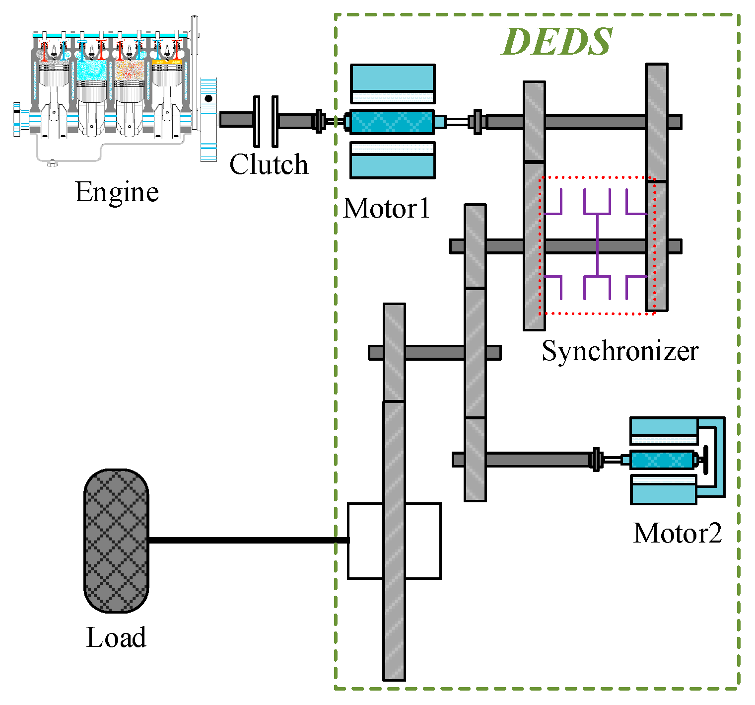
2. Electromechanical Coupling Dynamics Model of the DEDS of an HEV
Figure 1 shows the schematic diagram of a torque-coupled dual-motor electric drive system (DEDS) of a hybrid electric vehicle (HEV).
Figure 1.
Schematic diagram of a torque-coupled DEDS of an HEV.
2.1. Model of a PMSM
In modeling the motor for ease of analysis, it is assumed that the three-phase PMSM is an ideal motor. Therefore, the losses of the motor are neglected, the saturation of the core of the motor is not considered, and the three-phase currents are assumed to be symmetrical sinusoidal currents. The stator voltage equation of the motor in the d–q axis is shown below:
The equation of the electromagnetic torque is:
where ud and uq denote the stator voltage of the d–q axis, respectively; id and iq denote the stator current of the d–q axis, respectively; R denotes the stator resistance; denotes the electric angular velocity; Ld and Lq denote the inductance components of the d–q axis, respectively; denotes the flux linkage of permanent magnets; and Pn denotes the number of pole pairs in the motor. The parameters of the PMSM are shown in Table 1.
Table 1.
Parameters of PMSM.
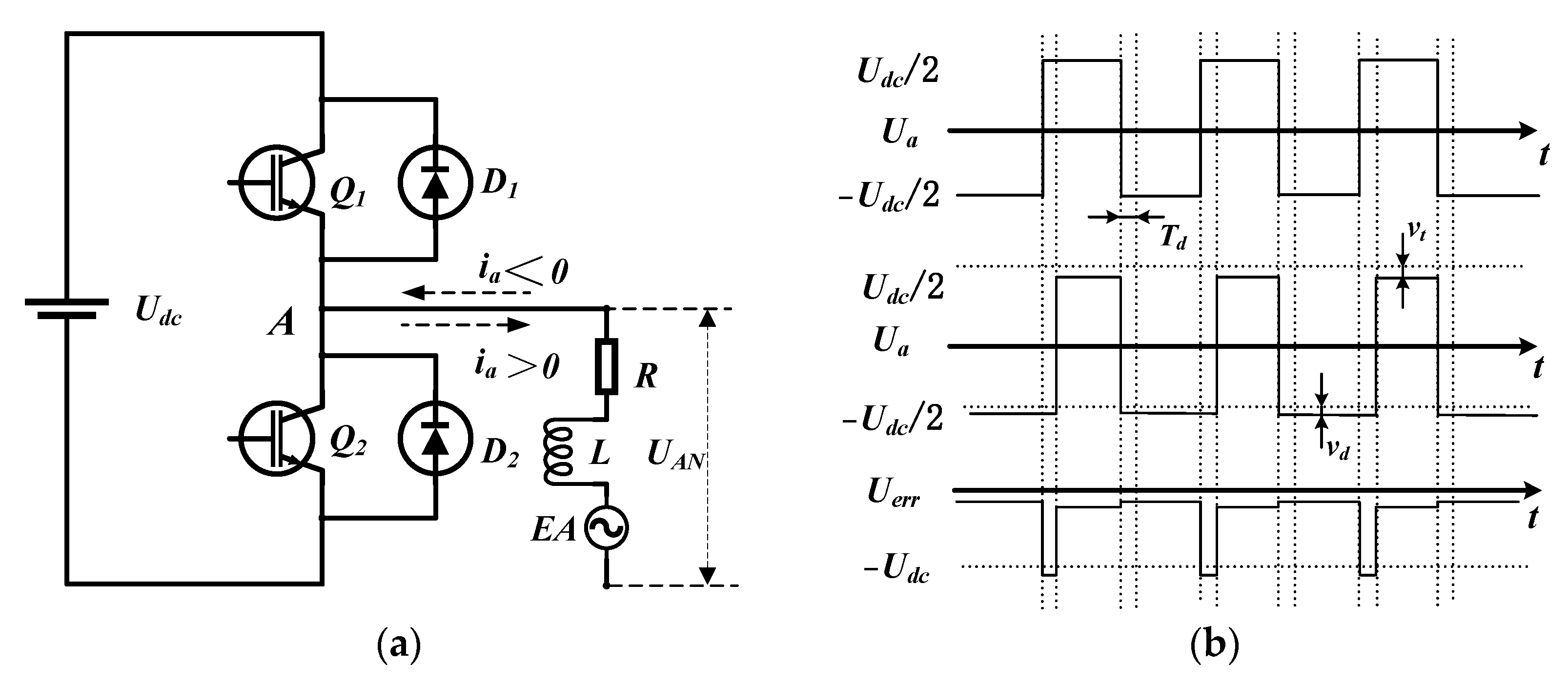
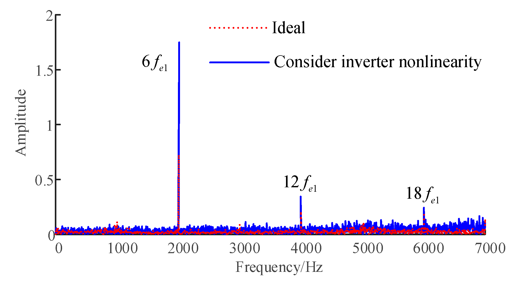
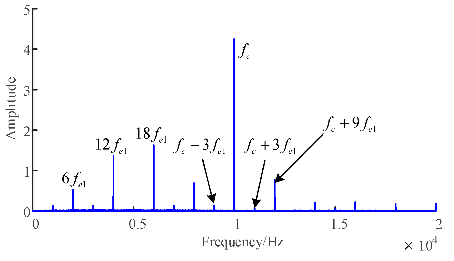
2.2. Nonlinear Model of the Inverter
In the motor control system, the role of the inverter is to turn the direct current (DC) voltage into alternating current voltage. The inverter circuit primarily consists of a three-phase bridge arm. To avoid the bridge arm breaking down and damaging the insulated gate bipolar transistor (IGBT), it is necessary to set a delay td to protect the transistor before the drive signal. The same two bridge arm transistors are in the off-state time, called dead time:
where Td denotes the dead time; td denotes the delay time; ton denotes the time required for the transistor to turn on; and toff denotes the time required for the transistor to turn off.
Figure 2a shows that when the switching tube is turned on, a drop in the on-state voltage of the transistor occurs; when the switching tube is turned off, drop in the renewal voltage of the transistor occurs. The above reasons lead to many harmonic voltages in the actual output voltage of the inverter, which has a large deviation from the ideal voltage. The difference between the actual voltage and the ideal voltage is the error voltage, as shown in Figure 2b.
Figure 2.
Inverter A-phase bridge arm circuit and output voltage waveform: (a) inverter A-phase bridge arm structure diagram; (b) waveform of A-phase bridge arm signal when ia 0.
In a pulse width modulation (PWM) cycle, the error voltage is averaged over the cycle time, according to the area equivalence principle, to obtain the average error voltage:
where vt denotes the on-state voltage drop of the switching tube; vd denotes the off-state voltage drop of the current-continuing diode.
Fourier decomposition of the signal yields an expression for the average error voltage of the inverter [21]:
From the Fourier decomposition results, the nonlinearity of the inverter generates many harmonic components into the motor current, which causes the motor to produce harmonic currents. PMSM stator windings mostly adopt star connections, so the third and integer third harmonic components of the stator current cannot flow. The parameters of the inverter are shown in Table 2.
Table 2.
Permanents of the inverter.
From Figure 3, the nonlinearity of the inverter of motor 1 under rated operating conditions (rated speed, rated load) causes 6th-order, 12th-order, and 18th-order torque fluctuations, of which, the amplitude of the sixth harmonic component is the largest, verifying the theoretical analysis of the nonlinear characteristics of the inverter.
Figure 3.
Frequency domain of PMSM electromagnetic torque.
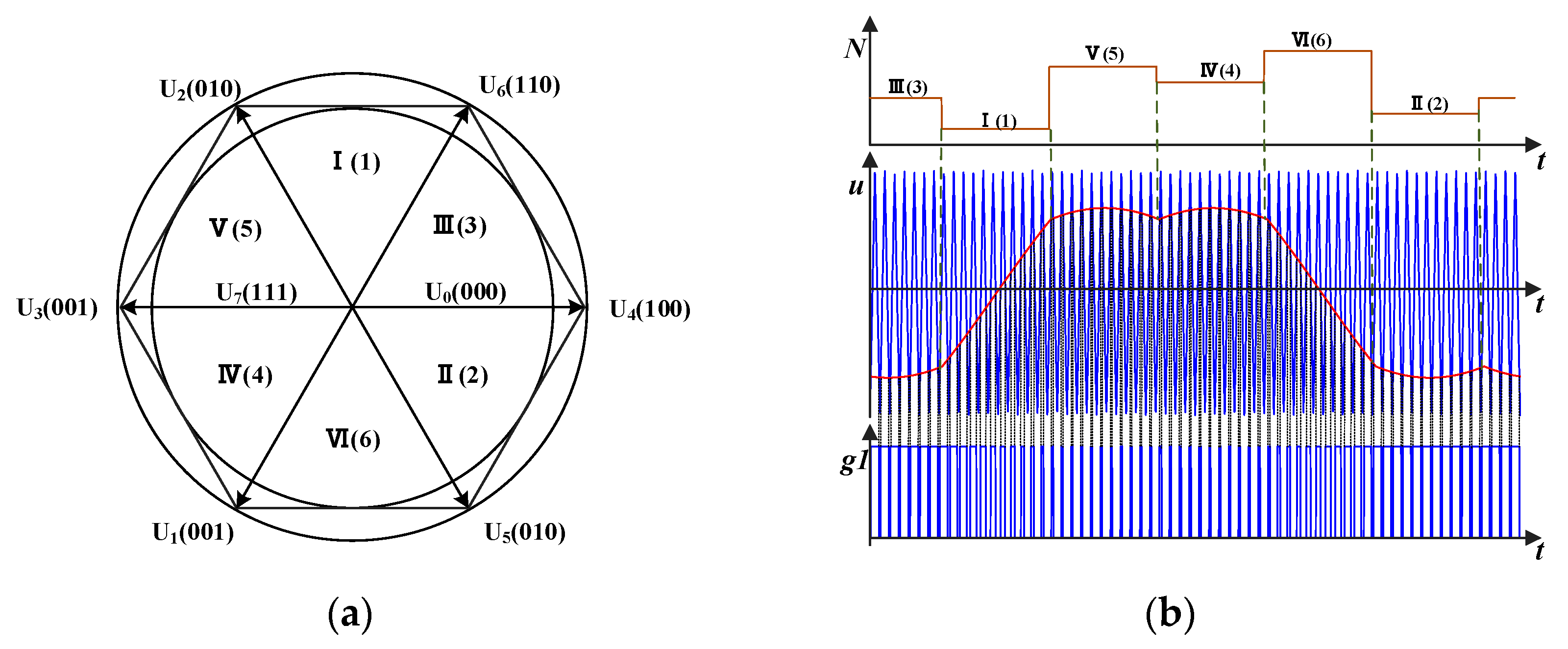
2.3. Implementation of the SVPWM Algorithm
In the field of inverter control for automotive permanent magnet synchronous motors, seven-segment space vector pulse width modulation (SVPWM) algorithms are mostly used to control the operation of the inverters. As shown in Figure 4a, eight combinations of spatial voltage vectors divide the complex plane into six sectors, and within a switching cycle, the SVPWM algorithm takes two fundamental voltage vectors within a sector so that their average value is equal to the voltage vector of a given demand. As shown in Figure 4b, the switching time point of the inverter in the sector where the demand voltage vector is located is obtained through calculation, and the switching time point of the inverter is compared with the triangle carrier signal to generate the PWM pulse signal.
Figure 4.
SVPWM algorithm implementation diagram: (a) voltage vector space diagram; (b) schematic diagram of PWM pulse signal generation.
Based on the average equivalence principle, the SVPWM algorithm uses a segmented approximation of the voltage vector to drive the motor, which will cause current harmonic currents, and thus torque fluctuations. The Fourier series expansion of the voltage output from the inverter is [22]:
where wc denotes carrier frequency and wr denotes modulated wave frequency.
Figure 5 shows the electromagnetic torque of motor 1 under rated operating conditions. In the low-frequency region, the sixth nth-order harmonic component dominates, and in the high-frequency region, it is mainly the PWM switching frequency fc, and its side band has a current frequency. The format is presented as |a fe1 ± fc| (a = 1, 2, …).
Figure 5.
Electromagnetic torque frequency domain.
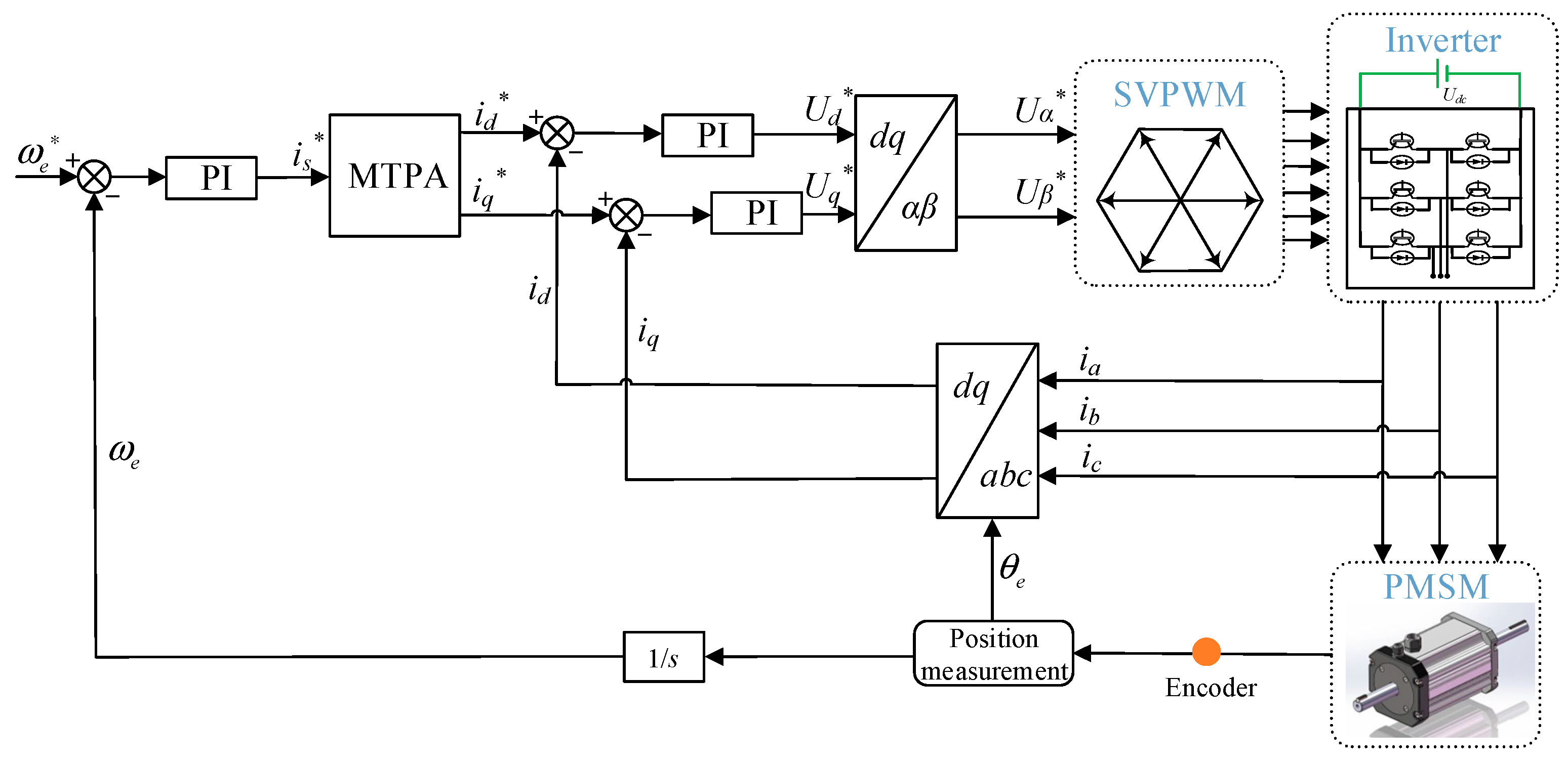
2.4. Vector Control Model for PMSM
Figure 6 shows the vector control block diagram of the three-phase PMSM, which is primarily composed of the speed loop, current loop, maximum torque per ampere, SVPWM, the inverter, etc. Where denotes the target speed of motor; is* denotes the target current; id* and iq* denote the current instructions of d and q axis, respectively; Ud* and Uq* denote the voltage instructions of d and q axis, respectively; Uα* and Uβ* denote the voltage instructions of SVPWM.
Figure 6.
Block diagram of the three-phase PMSM vector control model.
2.5. Model of Gear System Dynamic of the DEDS
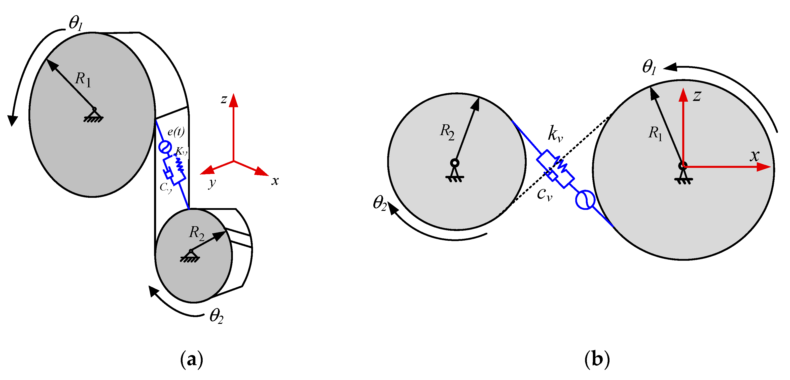
2.5.1. Model of Gear Pair Torsional Vibration
Considering the torsional vibration of the gear, a dynamic model of the torsional vibration of the gear transmission system is established, as shown in Figure 7.
Figure 7.
Torsional vibration model of helical gear pair: (a) stress diagram; (b) transmission diagram.
The meshing displacement of the gear along the line of engagement is [23]:
where θ1 and θ2 denote the rotation angles of the main and driven gears, respectively; R1 and R2 denote the gear index circle radii; and e denotes a meshing error.
The dynamic meshing force of the gear considering meshing stiffness and damping is:
where denotes the gear pair meshing stiffness and denotes the gear pair meshing damping.
Then, the clearance functions are established, as follows [24]:
where 2b denotes the gear pair clearance, when the gear teeth are in a normal meshing state; when f(x) = x−b, the gear teeth are in normal engagement; when f(x) = 0, the gear teeth are in a separated state; and when f(x) = x+b, the meshing gear teeth are in the meshing state of the tooth back.
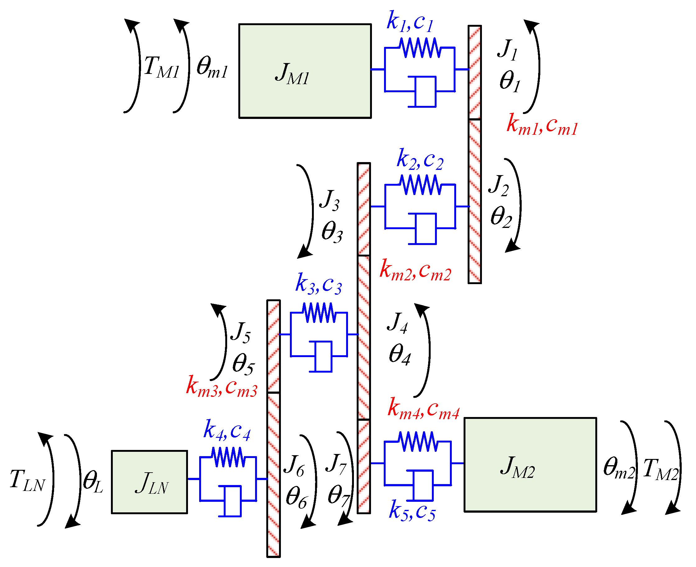
2.5.2. Dynamic Model of Transmission System
The components of the electromechanical drive system are simplified as concentrated inertia, and the model of the electromechanical drive system’s dynamics is established considering the elastic torsional vibration and rigid body rotation of the gear system. In Figure 8, JM1, JM2, and JLN denote the rotational inertia of motor 1, motor 2, and load, respectively; Ji (i = 1, 2, …, 7) denotes the rotational inertia of the gear; gears 1 and 2 constitute the first gear pair; gears 3 and 4 constitute the second gear pair; gears 5 and 6 constitute the third gear pair; gears 4 and 7 constitute the fourth gear pair; θm1, θm2, and θL denote the rotational inertia of motor 1, motor 2, and load, respectively; θi (i = 1, 2, …, 7) denotes the angle of rotation of the i-th gear; kj and cj (j = 1, 2, …, 5) denote the stiffness and damping of the j-th shaft, respectively; kmj and cmj (j = 1, 2, 3, 4) denote the meshing stiffness and meshing damping of the j-th gear pair, respectively.
where Ri (i = 1, 2, …, 7) denotes the radius of the i-th gear base circle and Fa (a = 1, 2, 3, 4) denotes the meshing force of the a-th gear pair.
Figure 8.
Schematic diagram of the transmission system of the DEDS.
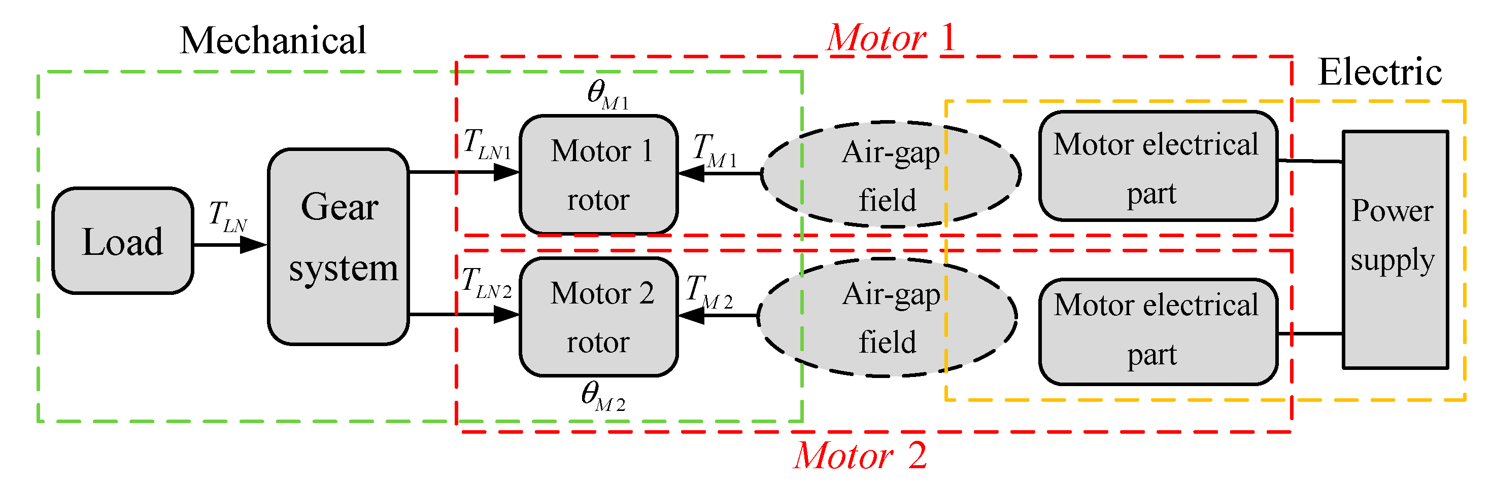
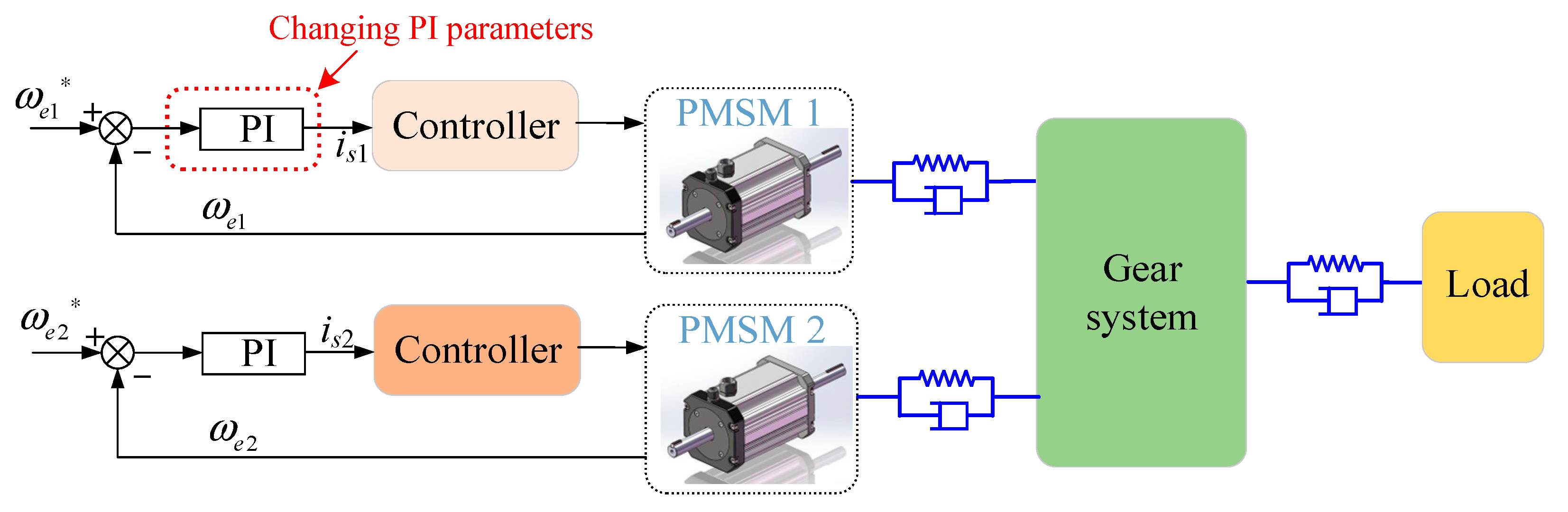
2.6. Electromechanical Coupling Model of the DEDS
The permanent magnet synchronous motor model established above was coupled with the gear transmission system model, as shown in Figure 9. The motor rotor is directly connected to the input shaft of the transmission system, the output speed of the permanent magnet synchronous motor is equal to the speed of the input shaft of the transmission system, and the load transmitted to the input shaft of the gear transmission system is used as the load of the PMSM. The electrical system and the mechanical systems are coupled, to obtain the electromechanical coupling model of the DEDS of an HEV; the expression of the coupled model is:
where J denotes the inertia matrix of the system; C denotes the damping matrix of the system; K denotes the stiffness matrix of the system; θ denotes the angular displacement matrix of the system; TLN denotes the load torque of the system; and TM denotes the electromagnetic torque of motor.
Figure 9.
Schematic diagram of the electromechanical coupling model of the DEDS.
The main parameters of the electromechanical coupling system are shown in Table 3. The coupled electromechanical system model of the DEDS of an HEV is established in MATLAB/Simulink, and simulated using the fourth- and fifth-order Runge–Kutta algorithms.
Table 3.
Parameters of the mechanical system.
2.7. Analysis of the Inherent Torsional Vibration Characteristics of the DEDS
According to the knowledge of vibration mechanics, ignoring the internal and external excitation and damping of the system, the free vibration equation of the torsional vibration model is obtained, as follows:
where J denotes the inertia matrix of the system; K denotes the stiffness matrix of the system; and θ denotes the angular displacement matrix of the system.
The eigenvalue problem corresponding to the free vibration equation is as follows:
where (i = 1, 2, …) denotes the natural frequency of the drive mode of motor 1 of the DEDS, and (i = 1, 2, …) denotes the natural frequency of the dual-motor drive mode of the DEDS. The natural frequencies of the driveline under different drive modes are shown in Table 4.
Table 4.
Natural frequencies of the driveline under different drive modes.
3. Analysis of Electromechanical Coupling Dynamics of the DEDS under Steady-State Conditions
To study the electromechanical coupling effect of the DEDS under steady-state conditions, a constant speed and constant load is applied to the system, and parallel control is applied to both motors in the dual-motor drive mode. The motor speed and system load torque under different operating conditions and driving modes are shown in Table 5. fet (t = 1, 2) denotes the current frequencies of motor 1 and motor 2, respectively; fmg (g = 1, 2, 3, 4) denotes the gear meshing frequency of each stage.
Table 5.
Parameter of the system under steady-state conditions.
3.1. Single-Motor Drive Mode
From Figure 10b, the main frequencies of motor 1′s current fluctuation are the current fundamental frequency fe1, and the harmonic frequencies 5fe1 and 7fe1 caused by the inverter’s nonlinear characteristics of in the single-motor drive mode, the harmonics caused by the nonlinearity of the inverter are marked in red in the figure. Because of the role of low-pass filtering of the motor circuit and the large inertia of the gear system, resulting in a small amplitude of the higher harmonics, the higher harmonics are not listed in this paper. In addition, the current spectrum contains mechanical system vibration frequencies, presented as |a fe1 ± b fmg|(a,b = 1, 2, …), which is due to the direct coupling of the electrical and mechanical parts through the motor shaft. The current’s fundamental frequency is modulated by the meshing frequency of gears, so that the current exhibits complex frequency characteristics, indicating that the operation of the gear system can be monitored by the current.
Figure 10.
Electrical system vibration response: (a) current time domain; (b) current frequency domain; (c) electromagnetic torque time domain; (d) electromagnetic torque PSD.
From Figure 10d, the electromagnetic torque power spectral density (PSD) contains abundant information on the meshing frequency of gears and the sixth harmonic component due to the nonlinear characteristics of the inverter, indicating that the electromagnetic torque fluctuations of the motor are mainly excited by the current harmonics and the gear meshing frequency in the DEDS.
It can be seen from Figure 11 that the meshing force of the first gear pair fluctuates up and down around the theoretical value, and the PSD contains the meshing frequencies of all gear pairs, indicating that the gear pairs interact with each other in the gear transmission. In addition, the sixth harmonic component appears in the PSD of the gear pairs, indicating that the mechanical system will be influenced by the harmonics of the electrical system during the operation of the DEDS, and that the DEDS presents a complex electromechanical coupling effect.
Figure 11.
The meshing force of the first gear pair in the single-motor drive mode: (a) time domain; (b) PSD.
3.2. Dual-Motor Drive Mode
From Figure 12b and Figure 13b, in the electromagnetic torque PSD of the two motors in the dual-motor drive mode, in addition to the sixth harmonic component generated by its inverter’s nonlinearity, the sixth harmonic component generated by the nonlinearity of the other motor’s inverter also appears. This is because the two motors are coupled together through the gearing system and affect each other in the dual-motor drive mode. Compared with the PSD of motor 1’s torque, there is no 3fm1 in the torque PSD of motor 2. The results show that there is a strong coupling effect between the two motors in the dual-motor drive mode.
Figure 12.
Motor 1’s electromagnetic torque: (a) time domain; (b) PSD.
Figure 13.
Motor 2’s electromagnetic torque: (a) time domain; (b) PSD.
As can be seen from Figure 14b, the PSD of the meshing force of the first gear pair contains the sixth harmonic component of both motors, generated by the nonlinearity of the inverter in the dual-motor drive mode. It shows that the gear transmission system suffers from harmonic excitation from both motors in the dual-motor drive mode, which aggravates the fluctuation of the meshing force of the gear pair.
Figure 14.
The meshing force of the first gear pair in the dual-motor drive mode: (a) time domain; (b) PSD.
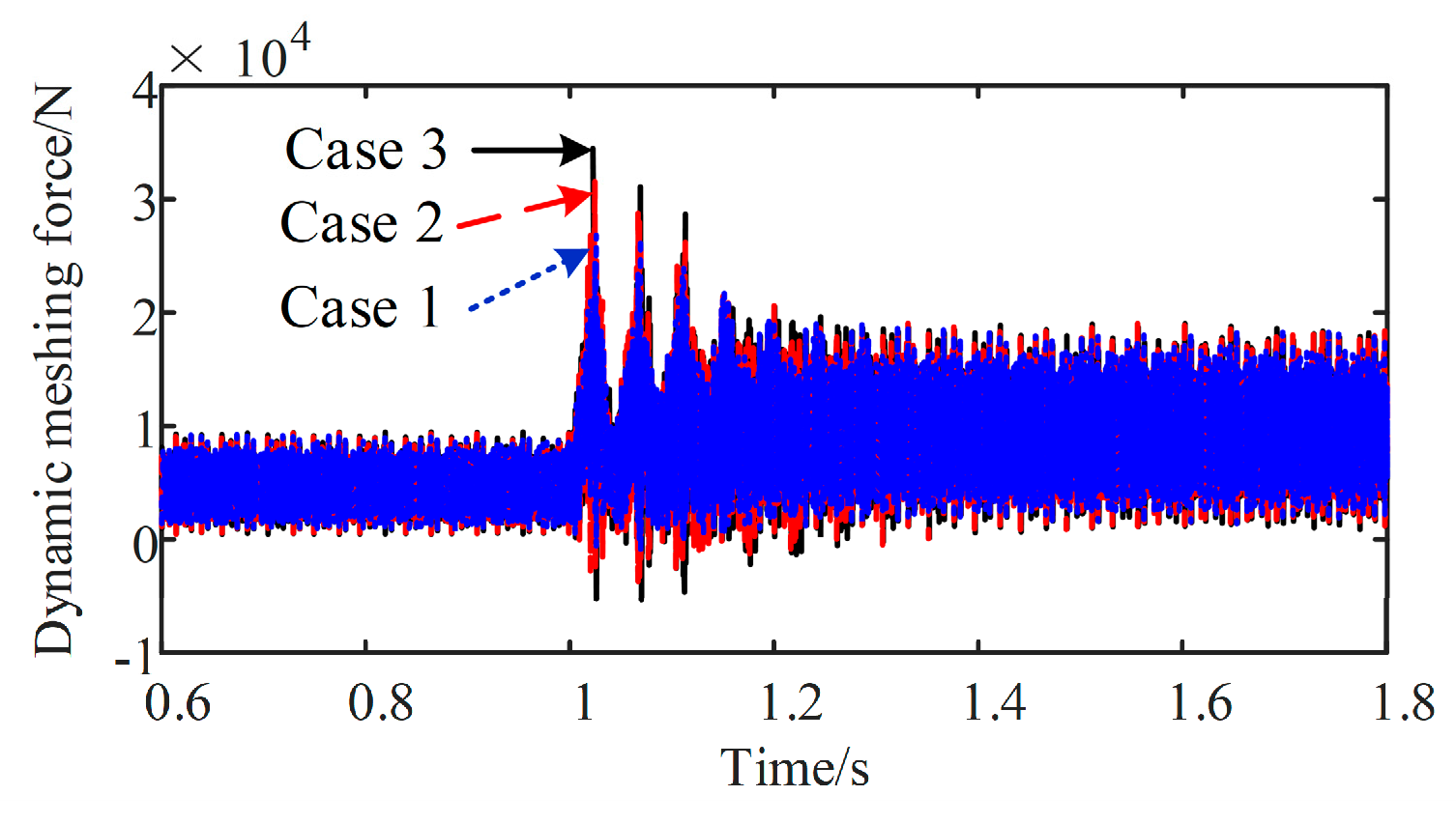
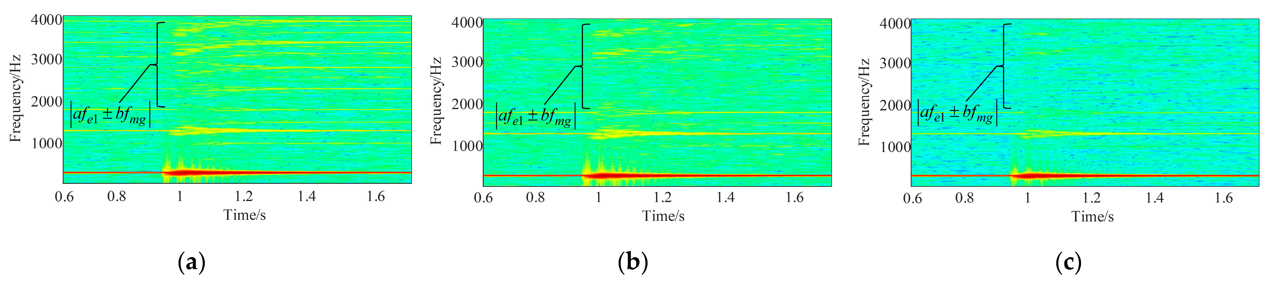
4. Analysis of Electromechanical Coupling Dynamics of the DEDS under Impact Conditions
When the dual-motor electric vehicle is driving in complex road conditions, such as speed bumps or uneven roads, the DEDS will be subjected to severe impact loads and continuous cyclic oscillations, which may cause serious fatigue damage to the electric drive system; therefore, it is meaningful to research the dynamic characteristics of the DEDS under impact conditions. The motor speed and system load torque under different operating conditions and driving modes are shown in Table 6.
Table 6.
Parameter of the system under impact conditions.
4.1. Single-Motor Drive Mode
To research the dynamic response characteristics of the single-motor drive mode of the DEDS under impact conditions, the system is simulated by applying an impact load. The motor speed is set to 3000 rpm, and the load of the DEDS changes abruptly from 1155 Nm to 2310 Nm in the first 1 s, as shown in Figure 15.
Figure 15.
Impact load.
Figure 16 and Figure 17 show the time domain and time-frequency domain of motor 1’s speed, and the meshing force of the first gear pair, respectively. The system generates instantaneous vibration, dominated by the first-order intrinsic frequency, when the DEDS encounters an impact load, and the torsional vibration process lasts approximately 0.58 s. This repeated impact is prone to cause fatigue damage to the gear drive system.
Figure 16.
Motor 1 speed: (a) time domain; (b) time-frequency domain (0–80 Hz).
Figure 17.
The meshing force of the first gear pair: (a) time domain; (b) time-frequency domain (0-80 Hz).
Figure 18 shows the response of the motor stator current during the impact process. After the DEDS suffers from the impact load, side frequencies of the form |fe1 ± fN1| appear on both sides of the power supply frequency with the system’s first-order natural frequency as the interval, indicating that the motor stator current has a certain ability to monitor the transient torsional vibration of the DEDS.
Figure 18.
Motor 1 stator current: (a) time domain; (b) time-frequency domain (0-450 Hz).
The PMSM and gear transmission system in the DEDS are directly connected by the motor shaft, so the stiffness and damping characteristics of the motor shaft directly determine the vibration response of the DEDS. To investigate the effect of different motor shaft stiffness damping values on the dynamic characteristics of the gear system caused by the impact load, and to verify the monitoring effect of the motor stator’s current on the vibration of the gear system, five combinations of motor shaft stiffness damping values are set up for simulation, as shown in Table 7.
Table 7.
Motor shaft damping and stiffness.
Figure 19 shows the time domain of the meshing force of the first gear pair with the same motor shaft connection stiffness and different connection damping, and as the motor shaft damping increases, the gear system’s torsional vibration is suppressed, but the excessive damping value aggravates the torsional vibration of the gear system. The above results indicate that the damping of the motor shaft can suppress the dynamic load of the gear pair caused by the impact load, and the suppression of the dynamic load increases with the increase in the damping value, and then decreases. From Figure 20 that different torsional vibration information of gears can be well reflected in stator current signals.
Figure 19.
The meshing force of the first gear pair with different connection damping.
Figure 20.
Time-frequency domain of the stator current of motor 1 with different values of motor shaft damping: (a) case 5; (b) case 3; (b) case 4.
According to Figure 21, a lower motor shaft stiffness can suppress the torsional vibrations of the gear system caused by impact loads. The motor shaft should thus be made of materials with lower stiffness. However, the stiffness of the motor shaft should not be too low, since the motor shaft must meet a certain strength threshold.
Figure 21.
The meshing force of the first gear pair with different connection stiffness.
From Figure 20 and Figure 22 it can be seen that after the system is subjected to an impact load, there is a sudden change in the amplitude of the frequency related to the gear meshing information in the motor stator current frequency, and the amplitude of the different torsional vibrations of the gear system can be reflected in the current signal. It shows that the motor stator current has an obvious feedback effect on the vibration of the gear system.
Figure 22.
Time-frequency domain of the stator current of motor 1 with different values of motor shaft stiffness: (a) case 3; (b) case 2; (c) case 1.
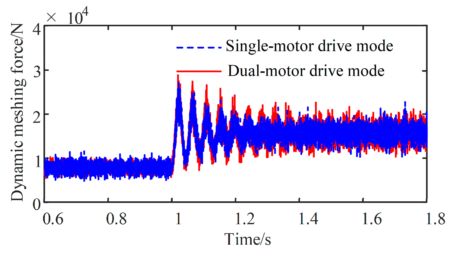
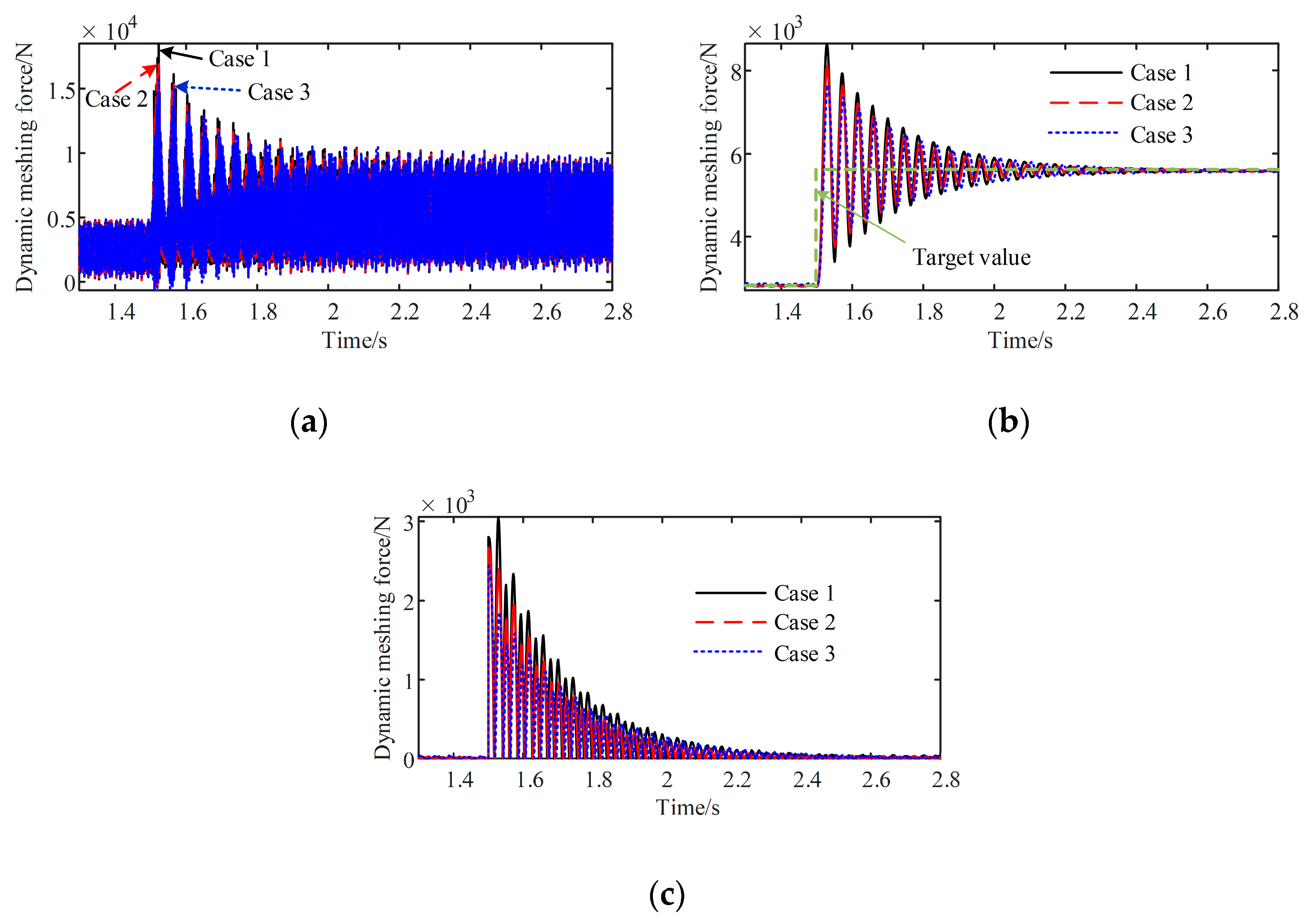
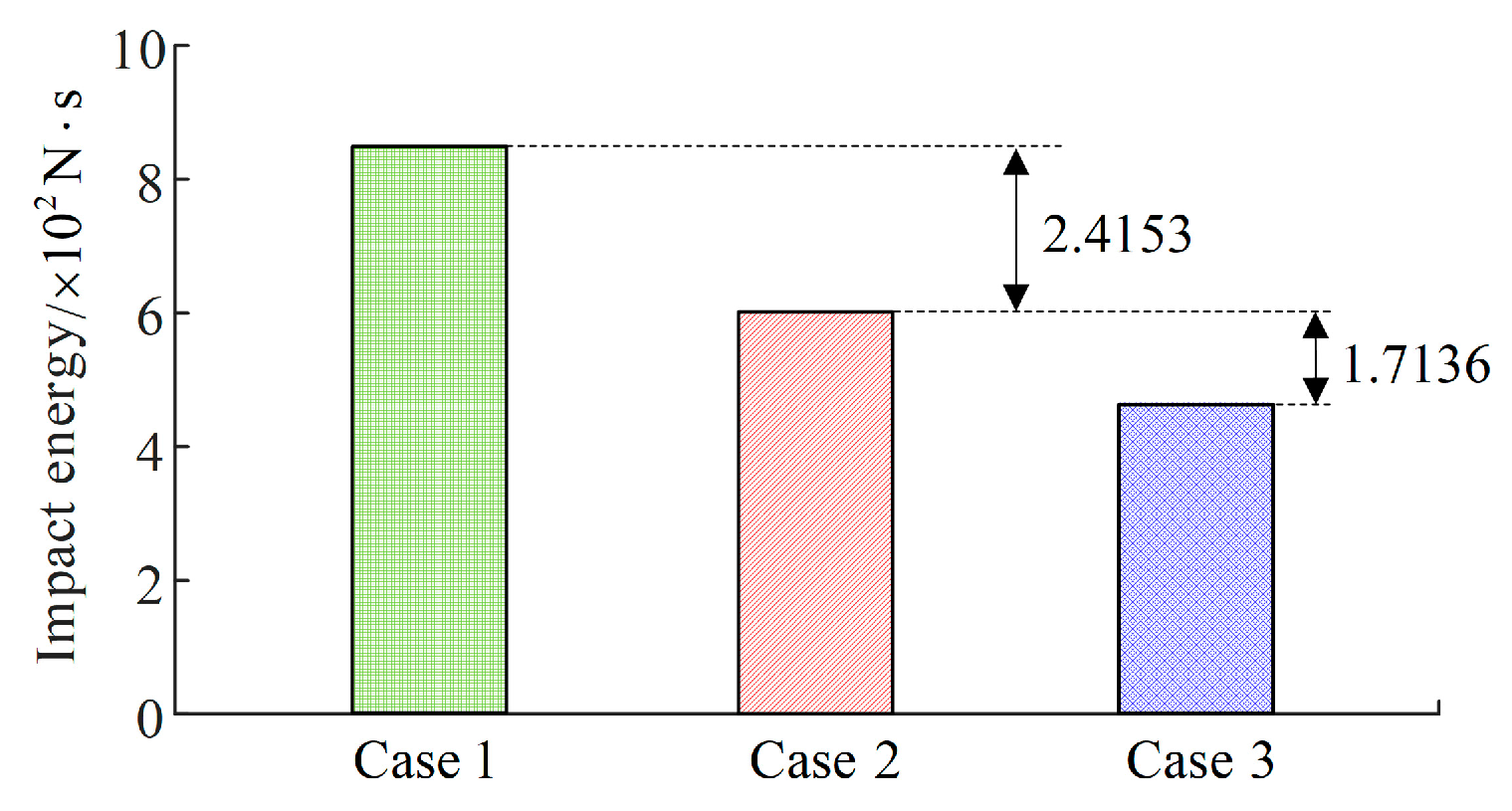
4.2. Dual-Motor Drive Mode
To investigate the dynamic response of the electromechanical coupling of the DEDS dual-motor drive mode under impact conditions, the speed of the two motors and the load of the system are shown in Figure 15.
The third gear pair is fully loaded in both single- and dual-motor drive modes, so it is necessary to compare the dynamic response of the third-stage gear pair in both modes with the other conditions held constant. As can be seen in Figure 23, the meshing force of the third gear pair oscillates at a greater amplitude under impact load conditions in the dual-motor drive mode.
Figure 23.
The meshing force of the third gear pair.
The cause of this phenomenon in Figure 23 may be the synchronization error of the speed of the two motors, which leads to the deterioration of the torsional vibration of the gear system. The expression of the synchronization error of the output speed of the two motors is as follows [25]:
where and denote the output speeds of motors 1 and 2, respectively, and Ke denotes the ratio factor of the speed of the two motors.
To verify the conjecture that the speed synchronization error will lead to the deterioration of the torsional vibration of the gear system under impact conditions, the speed synchronization error of the two motors is changed by varying the speed loop parameter of the proportional integral (PI) controller in the motor controller to make the motor speed fluctuate to different degrees according to the method of [26], as shown in Figure 24. Different combinations of the PI controller parameters are set as follows: case 1: P = 0.1, I = 80; case 2: P = 0.5, I = 80; case 3: P = 1, I = 80.
Figure 24.
Schematic diagram of PI parameter changes of the speed loop of motor 1.
The load of DEDS changes abruptly from 1155 Nm to 2310 Nm in 1.5 s. Figure 25b shows the relationship between motor 1’s speed and the speed synchronization error under different PI parameters. After changing the speed ring parameters of motor 1, the speed of motor 1 fluctuates to different degrees, and the synchronization error increases with the increase in the fluctuation amplitude of motor 1’s speed. The synchronization error under case 3 is the largest, and the synchronization error under case 1 is the smallest.
Figure 25.
Motor 1 speed and synchronization error under different combinations of PI parameters: (a) motor 1 speed; (b) synchronization error.
From Figure 26 it can be seen that the oscillation amplitude of the meshing force of the first gear pair increases with the increase in synchronization error after a sudden change in the external load of the system at 1.5 s. The above results indicate that the synchronization error aggravates the gear system’s torsional vibration in the dual-motor drive mode under impact conditions, and the torsional vibration of the gear system caused by the change in external load can be suppressed by reducing the synchronization error.
Figure 26.
The meshing force of the first gear pair: (a) meshing force of the first gear pair at time-varying meshing stiffness; (b) root mean square value of the meshing force of the first gear pair; (c) meshing force decay process.
To further analyze the effect of impact loads on the gear transmission system under different synchronization errors, the performance index of the absolute value of the error integral was used [27], i.e., the area enclosed by the actual dynamic meshing force curve due to the impact load and the vertical coordinate was obtained by integration. It was found that impact energy decreases with the decreasing area.
where S denotes impact energy; F(t) denotes the actual value of meshing force; and denotes the meshing force of the steady-state target value.
The statistical results of the impact energy generated by the first gear pair due to the impact load under different synchronization errors are given in Table 8 and Figure 27; the impact energy of the gear pair under impact load increases with the increase in the synchronization error.
Table 8.
Calculation results of the impact energy of the transmission system with different PI parameters.
Figure 27.
The impact energy of the transmission system with different PI parameters.
5. Conclusions
In this study, a torque-coupled DEDS of an HEV was taken as the research object. Considering the time-varying mesh stiffness of gears and the nonlinear characteristics of inverters, a model of the electromechanical coupling dynamics of the DEDS, including the PMSM and the gear transmission system, is established, and on this basis, the dynamic characteristics of the electromechanical coupling system in the single-motor drive mode and dual-motor drive mode were simulated and analyzed under steady-state and impact conditions. The main conclusions are as follows:
Under steady-state conditions, the motor stator’s current spectrum contains abundant gear meshing frequency information, present in the following format |a fe1 ± b fmg| (a,b = 1, 2, …); the stator current can be used as the monitoring signal of the steady-state healthy operation of the gear transmission system. The fluctuations of the electromagnetic torque and the dynamic meshing force of the gear pair are primarily excited by the meshing frequency of the gear pair at each level, and the harmonic frequency generated by the nonlinearity of the inverter; the electromagnetic torque spectrum of one motor in the dual-motor drive mode contains the harmonic components of the other motor, and the dynamic meshing force of the gear pair contains harmonic components of both motors in the frequency domain. There is an obvious electromechanical coupling effect between the electrical system and gear system of the DEDS. There is also a significant coupling effect between the two motors in the dual-motor drive mode.
The impact load causes the instantaneous torsional vibration of the transmission system dominated by the first-order natural frequency, and the vibration characteristic frequency appears in the form of the side frequency |fe1 ± fN1| in the stator current’s signal. This indicates that the stator current has a feedback effect on the torsional vibration of the system caused by the change in the external load; appropriate damping of the motor shaft and reducing its stiffness will reduce the torsional vibration of the gear system caused by impact load. The different torsional amplitude values of the gearing system can be reflected in the motor stator current’s frequency signal. Moreover, compared with the single-motor drive mode, the speed synchronization error of the dual-motor drive mode will aggravate the torsional vibration amplitude of the gear system under impact conditions. The impact energy caused by an external impact load on the gear system can be suppressed by reducing the speed synchronization error with appropriate control measures.
Author Contributions
S.G. conceived this research; S.H. wrote the original draft and deduced the calculation; editing and review of this article were completed by M.Y. All authors have read and agreed to the published version of the manuscript.
Funding
This work was supported by the National Natural Science Foundation of China (Grant No. 52005067, 52102423) and the Program for Innovation Team at the Institution of Higher Education in Chongqing (No. CXQT21027).
Data Availability Statement
Not applicable.
Conflicts of Interest
The authors declare no conflict of interest.
Nomenclature
| HEV | Hybrid electric vehicle | ||
| DEDS | Dual-motor electric drive system | ||
| PMSM | Permanent magnet synchronous motor | ||
| DC | Direct current | ||
| IGBT | Insulated gate bipolar transistor | ||
| SVPWM | Space vector pulse width modulation | ||
| PWM | Pulse width modulation | ||
| PSD | Power spectral density | ||
| PI | Proportional integral | ||
| Formula Symbols | |||
| Stator voltage of the d axis | Stator voltage of the q axis | ||
| Stator current of the d axis | Stator current of the q axis | ||
| Flux linkage of the d axis | Flux linkage of the q axis | ||
| Electric angular velocity | Stator resistance | ||
| Power of PMSM | Rated speed of PMSM | ||
| Rated Torque of PMSM | Flux linkage of permanent magnets | ||
| Inductance component of the d axis | Inductance component of the q axis | ||
| Battery direct current voltage | Number of pole pairs | ||
| Electromagnetic torque of PMSM 1 | Electromagnetic torque of PMSM 2 | ||
| Dead time of the inverter | Delay time of the inverter | ||
| IGBT turn-on time | IGBT turn-off time | ||
| Average error voltage of A-phase bridge | Conduction voltage drops of freewheeling diode | ||
| Pulse width modulation cycle | Voltage drops of IGBT switch | ||
| Modulated wave frequency | Modulation carrier frequency | ||
| Target speed of the motor | Target current | ||
| Current instruction of the d axis | Current instruction of the q axis | ||
| Voltage instruction of the d axis | Voltage instruction of the d axis | ||
| Voltage instruction of the SVPWM | Voltage instruction of the SVPWM | ||
| Carrier frequency | Meshing displacement of the gear | ||
| Gear pair meshing stiffness | Gear pair meshing damping | ||
| Gear meshing error | b | Gear pair clearance | |
| Rotational inertia of motor 1 | Stiffness of shaft 1 | ||
| Rotational inertia of motor 2 | Stiffness of shaft 2 | ||
| Rotational inertia of gear 1 | Stiffness of shaft 3 | ||
| Rotational inertia of gear 2 | Stiffness of shaft 4 | ||
| Rotational inertia of gear 3 | Stiffness of shaft 5 | ||
| Rotational inertia of gear 4 | Meshing force of gear pair 1 | ||
| Rotational inertia of gear 5 | Meshing force of gear pair 2 | ||
| Rotational inertia of gear 6 | Meshing force of gear pair 3 | ||
| Rotational inertia of gear 7 | Meshing force of gear pair 4 | ||
| Rotational inertia of load | Rotation angle of gear 1 | ||
| Damping of shaft 1 | Rotation angle of gear 2 | ||
| Damping of shaft 2 | Rotation angle of gear 3 | ||
| Damping of shaft 3 | Rotation angle of gear 4 | ||
| Damping of shaft 4 | Rotation angle of gear 5 | ||
| Damping of shaft 5 | Rotation angle of gear 6 | ||
| Radius of gear 1 | Rotation angle of gear 7 | ||
| Radius of gear 2 | Rotation angle of motor 1 | ||
| Radius of gear 3 | Rotation angle of motor 2 | ||
| Radius of gear 4 | Load torque of system | ||
| Radius of gear 5 | Load torque of motor 1 | ||
| Radius of gear 6 | Load torque of motor 1 | ||
| Radius of gear 7 | Angular displacement matrix of system | ||
| Motor 1 to load transmission ratio | Motor 2 to load transmission ratio | ||
| Inertia matrix of system | Stiffness matrix of system | ||
| Damping matrix of system | Meshing damping of gears | ||
| Natural frequency of motor 1 drive mode of system | Natural frequency of motor 2 drive mode of system | ||
| Current frequencies of motor 1 | Current frequencies of motor 2 | ||
| Meshing frequency of gear pair 1 | Meshing frequency of gear pair 2 | ||
| Meshing frequency of gear pair 3 | Meshing frequency of gear pair 4 | ||
| Speed of motors 1 | Speed of motors 2 | ||
| Average speed of two motors | Ratio factor of the speed of the two motors | ||
| Speed synchronization error | Impact energy | ||
| Actual value of dynamic meshing force | Dynamic meshing force steady-state target value | ||
References
- Liu, Y.; Tang, D.; Ju, J. Electromechanical Coupling Dynamic and Vibration Control of Robotic Grinding System for Thin-Walled Workpiece. Actuators 2023, 12, 37. [Google Scholar] [CrossRef]
- Yi, Y.; Tan, X.; Xuan, L.; Liu, C. Dynamic Interaction Behavior of an Electric Motor Drive Multistage Gear Set. IEEE Access 2020, 8, 66951–66960. [Google Scholar] [CrossRef]
- Zhang, K.; Yang, J.; Liu, C.; Wang, J.; Yao, D. Dynamic Characteristics of a Traction Drive System in High-Speed Train Based on Electromechanical Coupling Modeling under Variable Conditions. Energies 2022, 15, 1202. [Google Scholar] [CrossRef]
- Jiang, S.; Li, W.; Wang, Y.; Yang, X.; Xu, S. Study on Electromechanical Coupling Torsional Resonance Characteristics of Gear System Driven by PMSM: A Case on Shearer Semi-direct Drive Cutting Transmission System. Nonlinear Dyn. 2021, 104, 1205–1225. [Google Scholar] [CrossRef]
- Abouzeid, A.F.; Guerrero, J.M.; Vicente-Makazaga, I.; Muniategui-Aspiazu, I.; Endemano-Isasi, A.; Briz, F. Torsional Vibration Suppression in Railway Traction Drives. IEEE Access 2022, 10, 32855–32869. [Google Scholar] [CrossRef]
- Sheng, L.; Li, W.; Jiang, S.; Chen, J.; Liu, A. Nonlinear Torsional Vibration Analysis of Motor Rotor System in Shearer Semi-direct Drive Cutting Unit under Electromagnetic and Load Excitation. Nonlinear Dyn. 2019, 96, 1677–1691. [Google Scholar] [CrossRef]
- Li, Y.; Wu, H.; Xu, X.; Cai, Y.; Sun, X. Analysis on electromechanical coupling vibration characteristics of in-wheel motor in electric vehicles considering air gap eccentricity. Bull. Pol. Acad. Sci. Tech. Sci. 2019, 67, 851–862. [Google Scholar] [CrossRef]
- Hu, J.; Peng, T.; Jia, M.; Yang, Y.; Guan, Y. Study on Electromechanical Coupling Characteristics of an Integrated Electric Drive System for Electric Vehicle. IEEE Access 2019, 7, 166493–166508. [Google Scholar] [CrossRef]
- Chen, R.; Liu, C.; Qin, D. Electromechanical Dynamic Analysis of the Integrated System of Switched Reluctance Motor and Planetary Gear Transmission. J. Vib. Eng. Technol. 2022, 10, 581–599. [Google Scholar] [CrossRef]
- Huo, J.; Wu, H.; Sun, W.; Zhang, Z.; Wang, L.; Dong, J. Electromechanical Coupling Dynamics of TBM Main Drive System. Nonlinear Dyn. 2017, 90, 2687–2710. [Google Scholar] [CrossRef]
- Chen, X.; Han, S.; Li, J.; Deng, T.; Wei, H. Investigation of Electromechanical Coupling Lateral/torsional Vibration in a High-speed Rotating Continuous Flexible Shaft of PMSM. Appl. Math. Model. 2020, 77, 506–521. [Google Scholar] [CrossRef]
- Shi, X.; Sun, D.; Kan, Y.; Zhou, J.; You, Y. Dynamic Characteristics of a New Coupled Planetary Transmission under Unsteady Conditions. J. Braz. Soc. Mech. Sci. Eng. 2020, 42, 280. [Google Scholar] [CrossRef]
- Fan, W.; Yang, Y.; Su, X. Dynamic Modeling and Vibration Characteristics Analysis of Transmission Process for Dual-Motor Coupling Drive System. Symmetry 2020, 12, 1171. [Google Scholar] [CrossRef]
- Hu, C.; Tang, X.; Zou, L.; Yang, K.; Li, Y.; Zheng, L. Numerical and Experimental Investigations of Noise and Vibration Characteristics for a Dual-motor Hybrid Electric Vehicle. IEEE Access 2019, 7, 77052–77062. [Google Scholar] [CrossRef]
- Wang, W.; Li, Y.; Shi, J.; Lin, C. Vibration Control Method for an Electric City Bus Driven by a Dual Motor Coaxial Series Drive System Based on Model Predictive Control. IEEE Access 2018, 6, 41188–41200. [Google Scholar] [CrossRef]
- Yue, H.; He, H.; Han, M. Study on Torsional Vibration Characteristics and Suppression of Electric Vehicles with Dual-motor Drive System. J. Frankl. Inst. 2023, 360, 380–402. [Google Scholar] [CrossRef]
- Wei, J.; Shu, R.; Qin, D.; Lim, T.C.; Zhang, A. Study of Synchronization Characteristics of a Multi-source Driving Transmission System under an Impact Load. Int. J. Precis. Eng. Manuf. 2016, 17, 1157–1174. [Google Scholar] [CrossRef]
- Xiong, H.; Zhang, M.; Zhang, R. A New Synchronous Control Method for Dual Motor Electric Vehicle Based on Cognitive-inspired and Intelligent Interaction. Future Gener. Comput. Syst. 2019, 94, 536–548. [Google Scholar] [CrossRef]
- Wang, D.; Yang, F.; Jiang, X.; Shi, S.; Ma, S. Electromechanical Coupling Dynamic Characteristics of Differential Speed Regulation System Considering Inverter Harmonics under Variable Operating Conditions. IEEE Access 2022, 10, 12057–12069. [Google Scholar] [CrossRef]
- Han, L.; Wang, D.; Yang, F.; He, W. Vibration Characteristics of the Dual Electric Propulsion System of Vessels under Electromechanical Coupling Excitation. Machines 2022, 10, 449. [Google Scholar] [CrossRef]
- Zhang, Q.; Fan, Y. The Online Parameter Identification Method of Permanent Magnet Synchronous Machine under Low-Speed Region Considering the Inverter Nonlinearity. Energies 2022, 15, 4314. [Google Scholar] [CrossRef]
- Ge, S.; Qiu, L.; Zhang, Z.; Guo, D.; Ren, H. Integrated Impacts of Non-Ideal Factors on the Vibration Characteristics of Permanent Magnet Synchronous Motors for Electric Vehicles. Machines 2022, 10, 73. [Google Scholar] [CrossRef]
- Hu, J.; Yang, Y.; Jia, M.; Guan, Y.; Fu, C.; Liao, S. Research on Harmonic Torque Reduction Strategy for Integrated Electric Drive System in Pure Electric Vehicle. Electronics 2020, 9, 1241. [Google Scholar] [CrossRef]
- Chen, Z.; Ning, J.; Wang, K.; Zhai, W. An Improved Dynamic Model of Spur Gear Transmission Considering Coupling Effect between Gear Neighboring Teeth. Nonlinear Dyn. 2021, 106, 339–357. [Google Scholar] [CrossRef]
- Shu, R.; Wei, J.; Tan, R.; Wu, X.; Fu, B. Investigation of Dynamic and Synchronization Properties of a Multi-motor Driving System: Theoretical Analysis and Experiment. Mech. Syst. Signal Process. 2021, 153, 107496. [Google Scholar] [CrossRef]
- Li, M.; Yang, Y.; Hu, M.; Qin, D. Influence of Motor Control Characteristics on Load Sharing Behavior of Torque Coupling Gear Set. J. Vibroeng. 2016, 18, 4539–4549. [Google Scholar] [CrossRef]
- Zhu, E.; Pang, J.; Sun, N.; Gao, H.; Sun, Q.; Chen, Z. Airship Horizontal Trajectory Tracking Control Based on Active Disturbance Rejection Control (ADRC). Nonlinear Dyn. 2014, 75, 725–734. [Google Scholar] [CrossRef]
Disclaimer/Publisher’s Note: The statements, opinions and data contained in all publications are solely those of the individual author(s) and contributor(s) and not of MDPI and/or the editor(s). MDPI and/or the editor(s) disclaim responsibility for any injury to people or property resulting from any ideas, methods, instructions or products referred to in the content. |
© 2023 by the authors. Licensee MDPI, Basel, Switzerland. This article is an open access article distributed under the terms and conditions of the Creative Commons Attribution (CC BY) license (https://creativecommons.org/licenses/by/4.0/).