
Sequence Control Strategy for Grid-Forming Voltage Source Converters Based on the Virtual-Flux Orientation under Balanced and Unbalanced Faults

 , ,
, ,  and
and
Abstract
1. Introduction
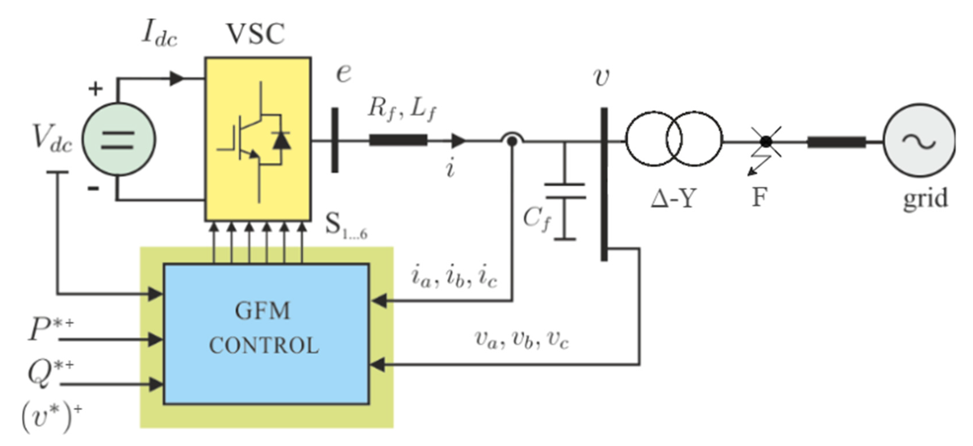
2. System Description
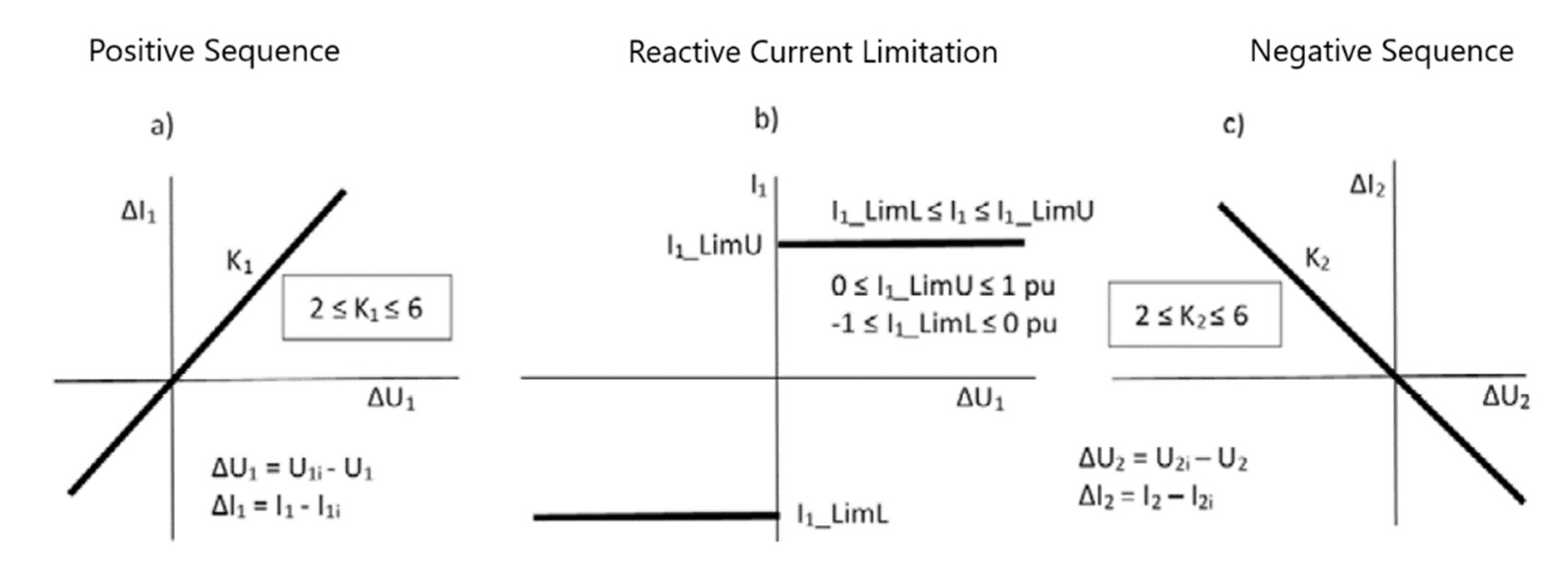
3. Spanish Grid Code Requirements under Balanced and Unbalanced Faults Review
4. Sequence Control Strategy
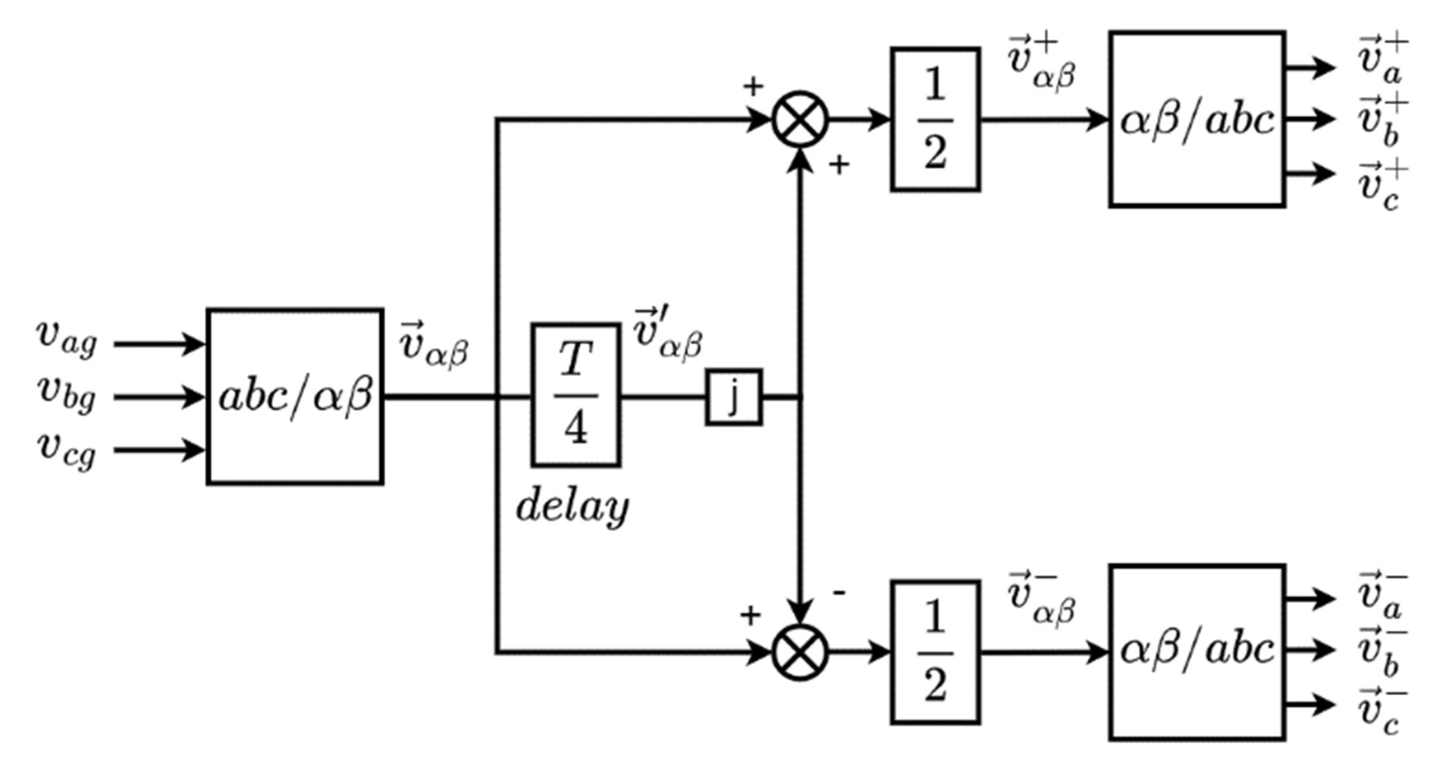
4.1. Sequences Extraction Algorithm
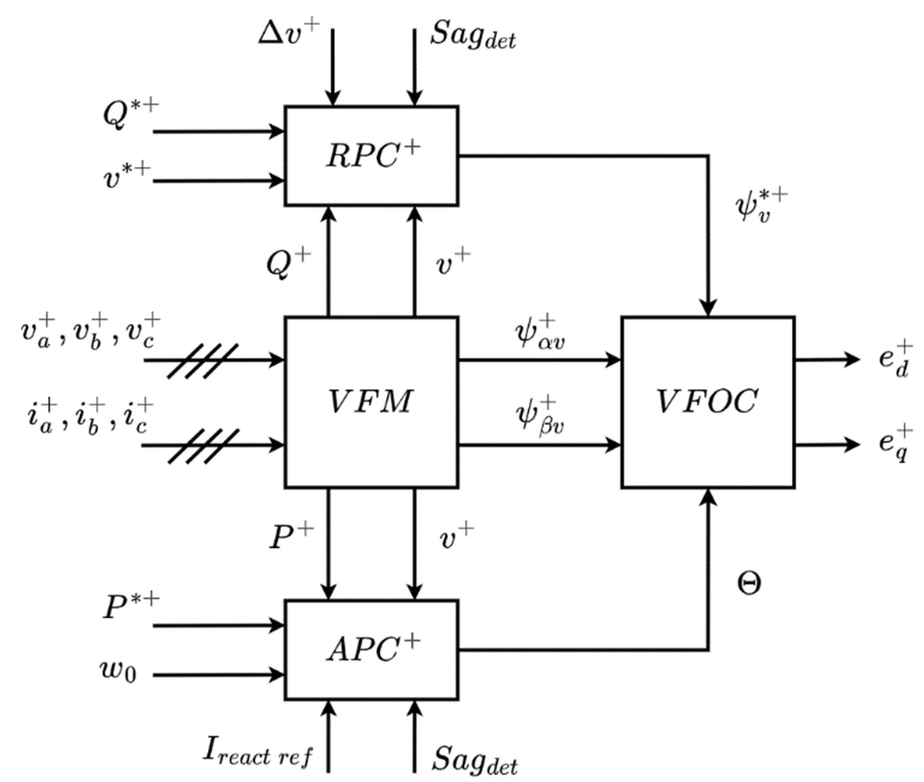
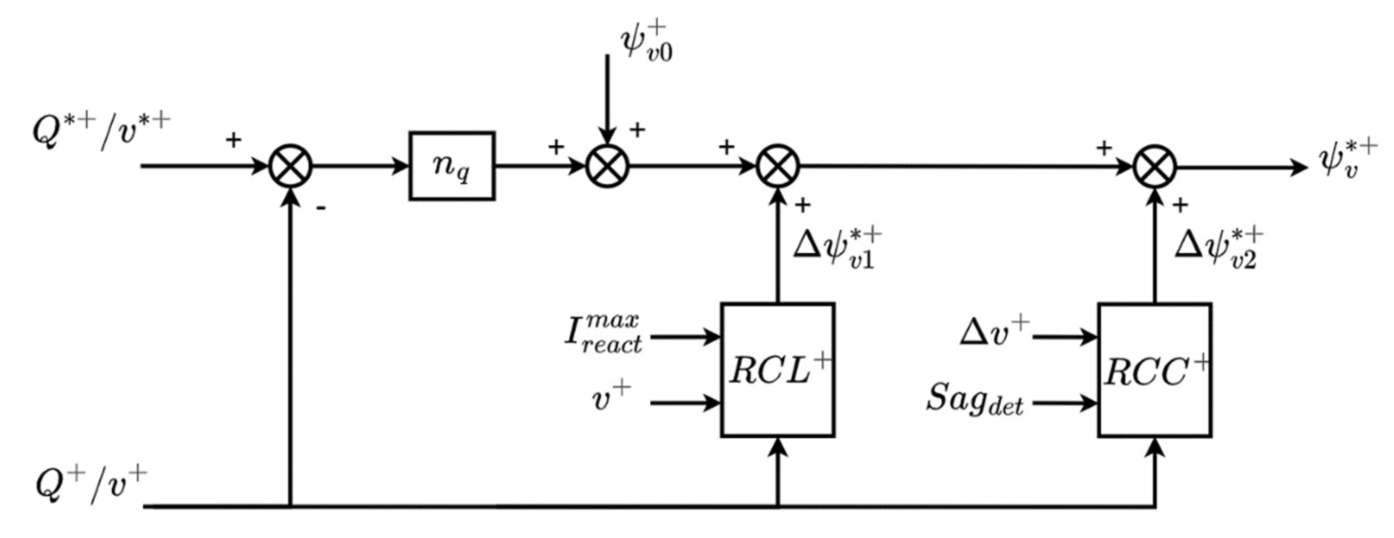
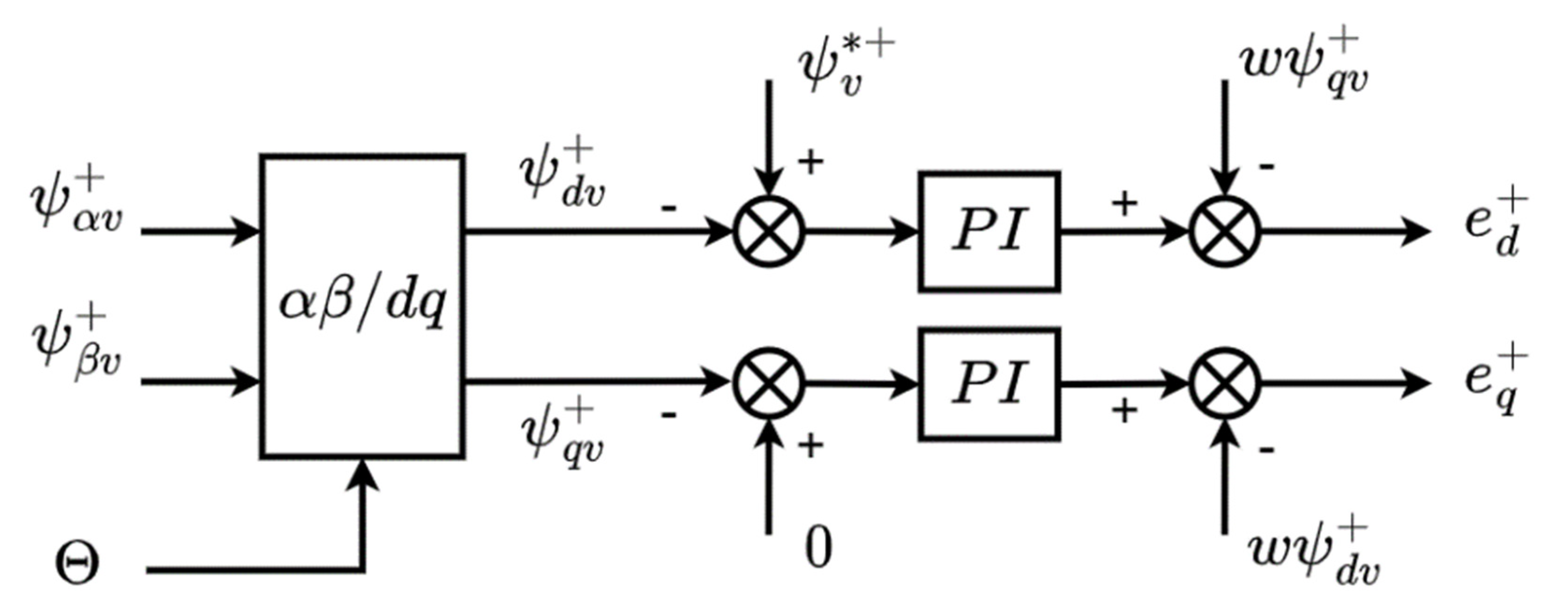
4.2. Positive Sequence Control Scheme
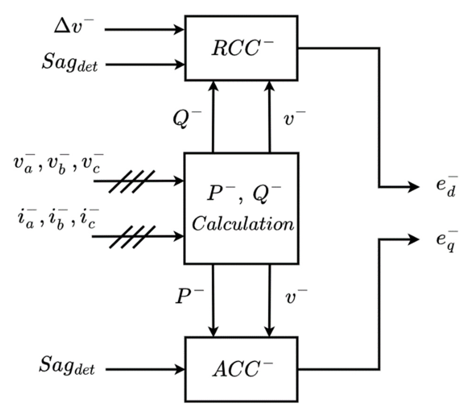
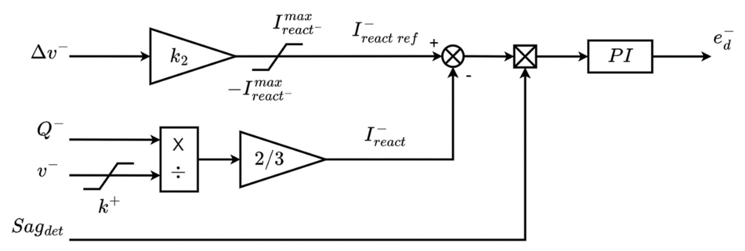
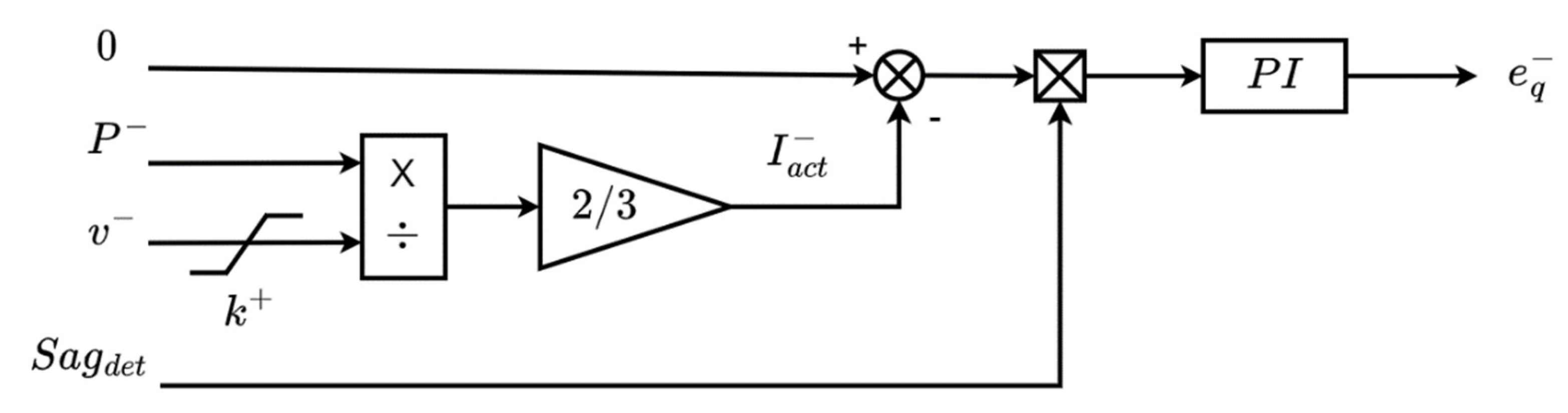
4.3. Negative Sequence Control Scheme
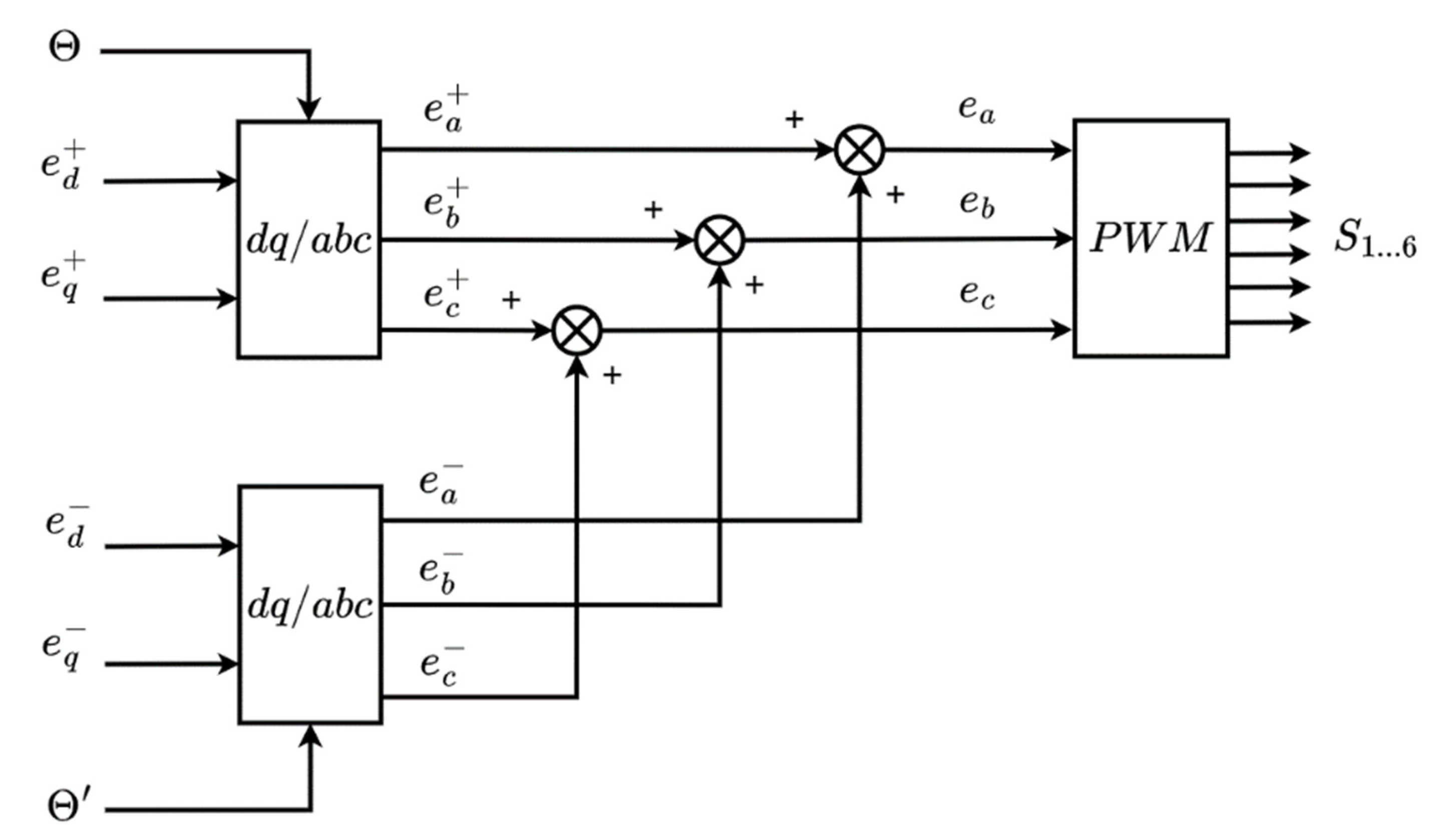
4.4. Converter Voltage Setpoints Calculation
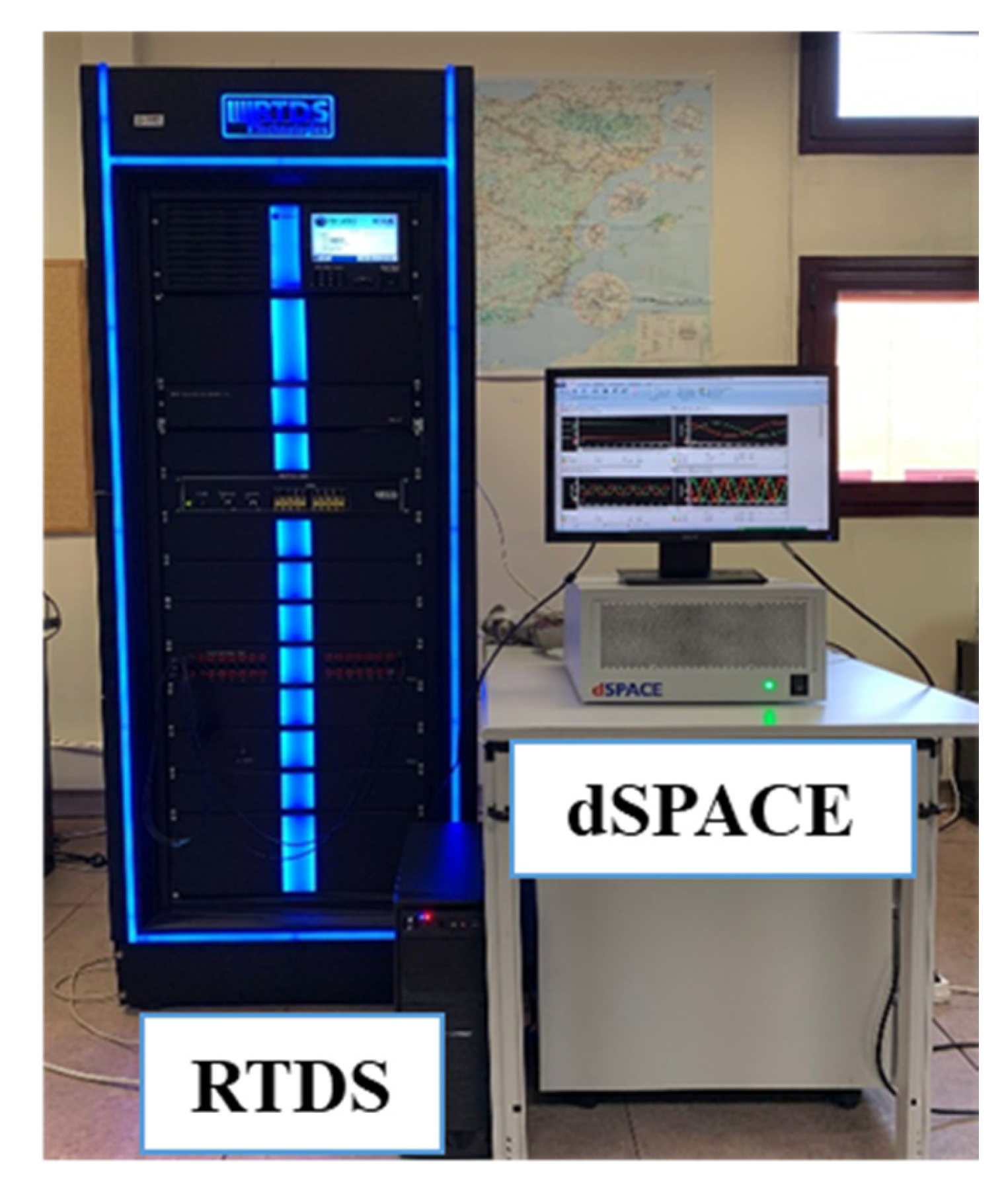
5. Real-Time HIL Simulation Results
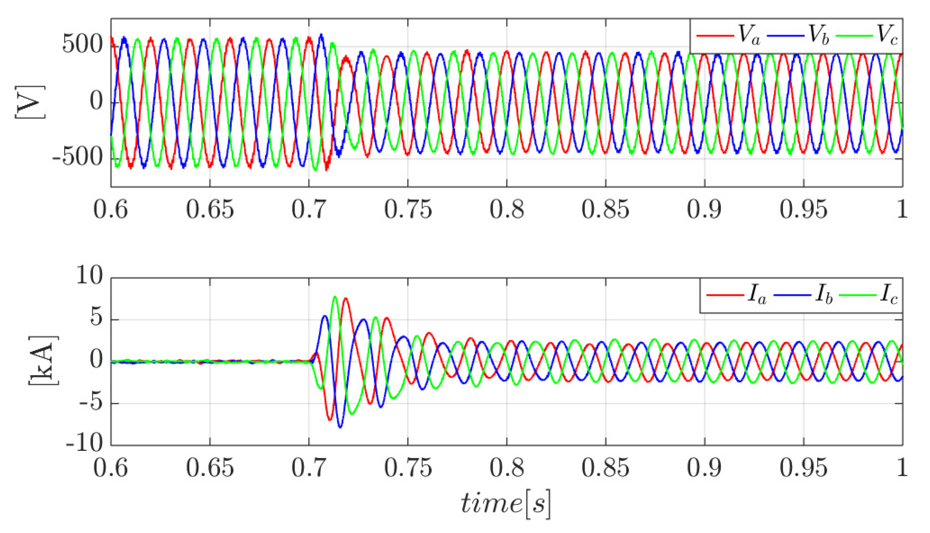
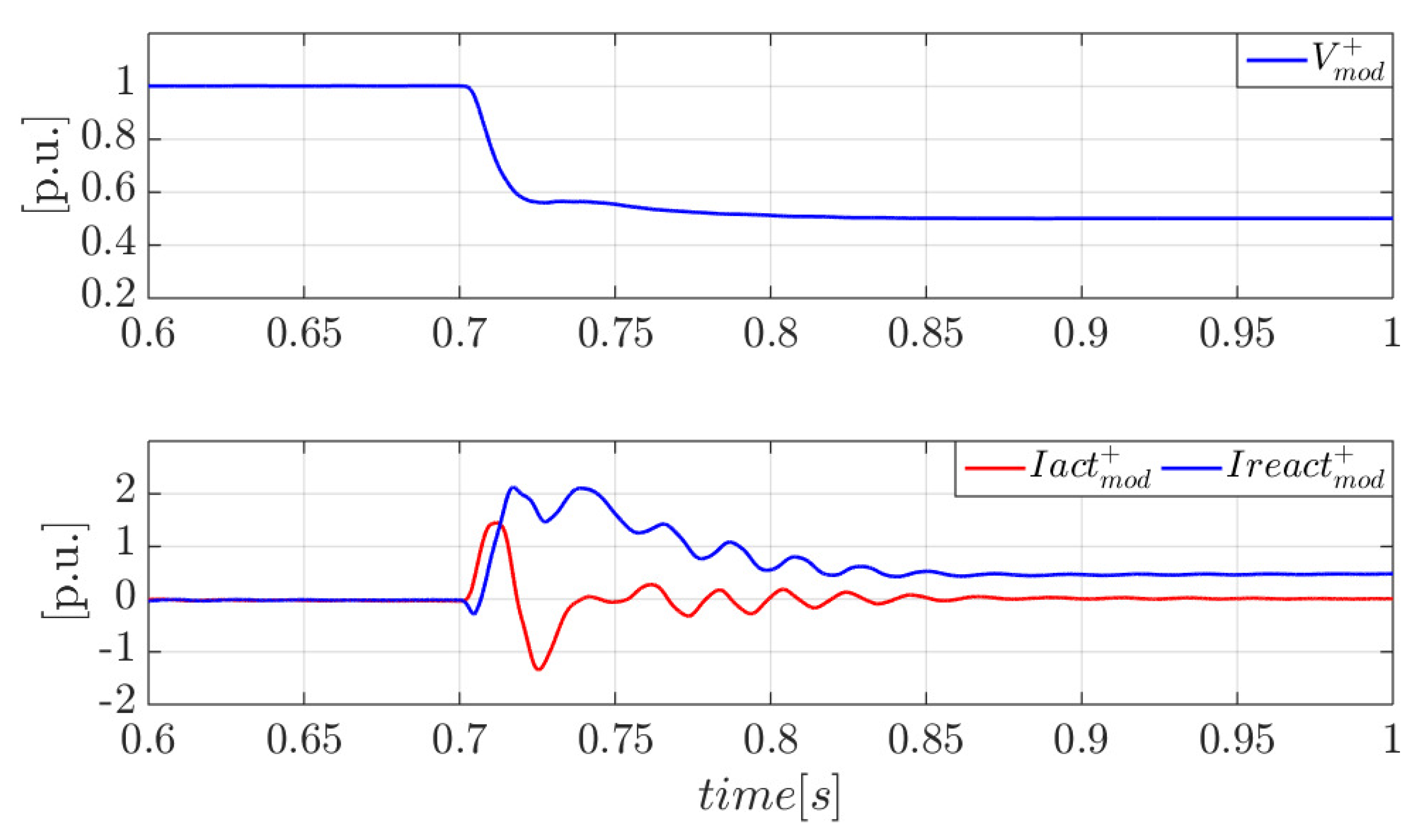
5.1. Balanced Three-Phase Faults
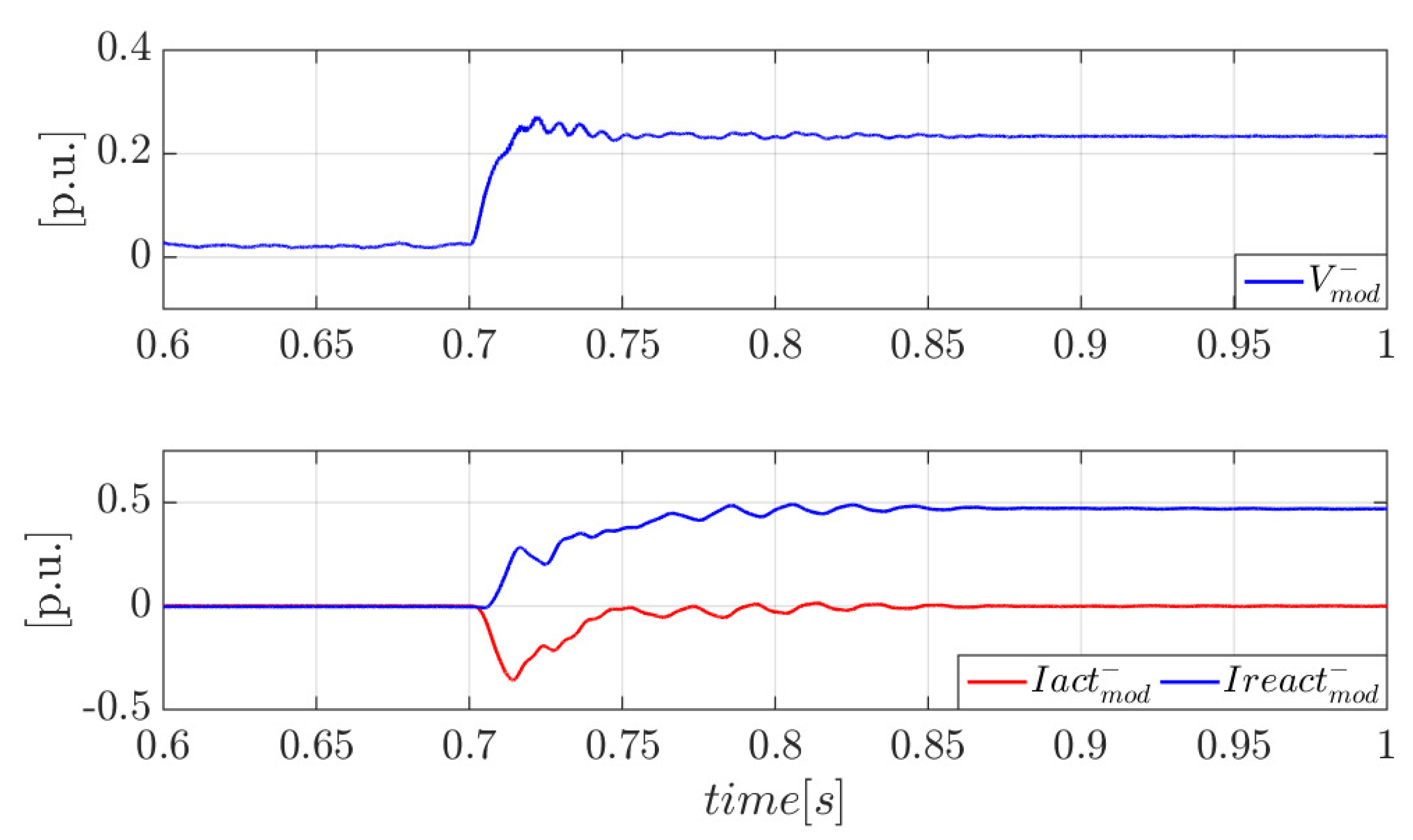
5.2. Unbalanced Phase-to-Phase Faults
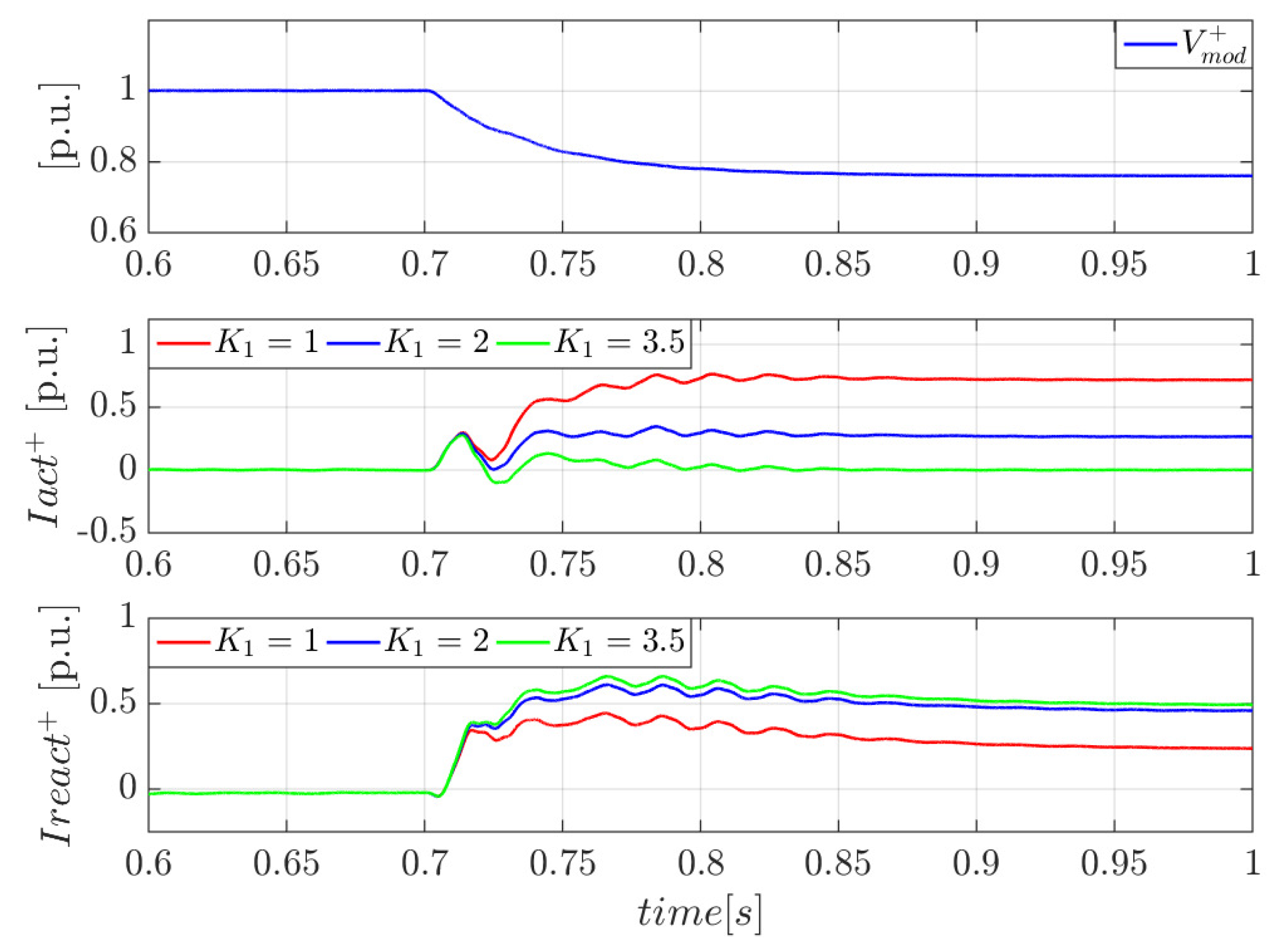
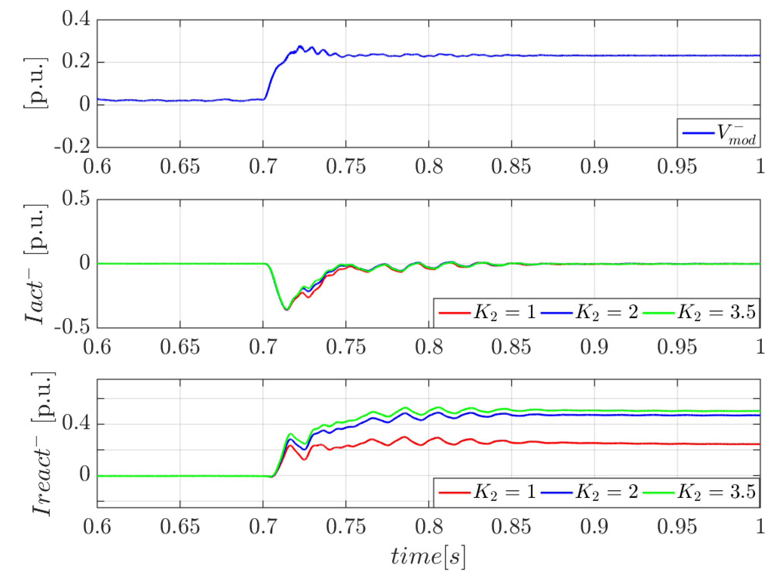
5.3. Converter Response to Unbalanced Phase-to-Phase Faults for Different Values of and
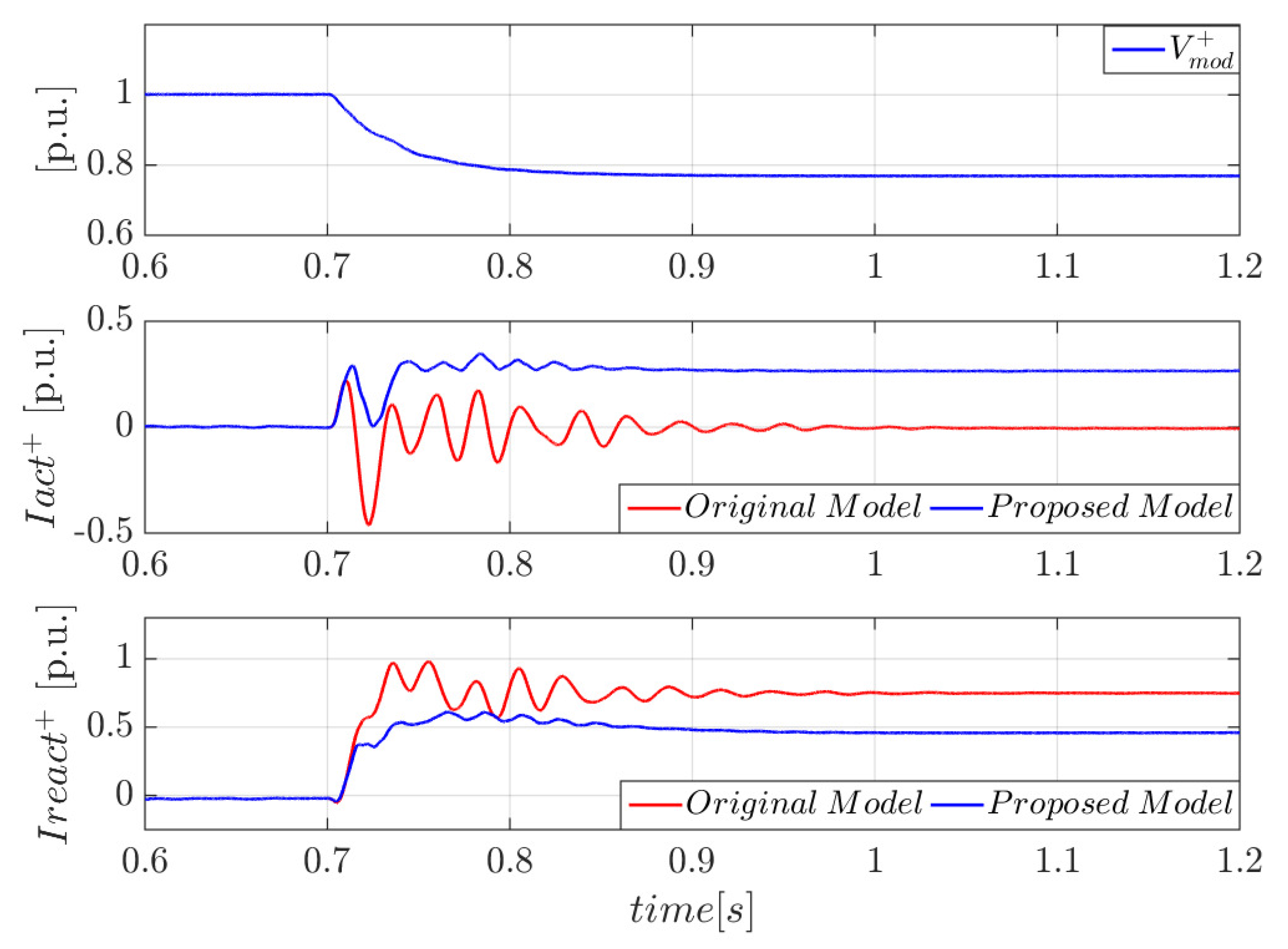
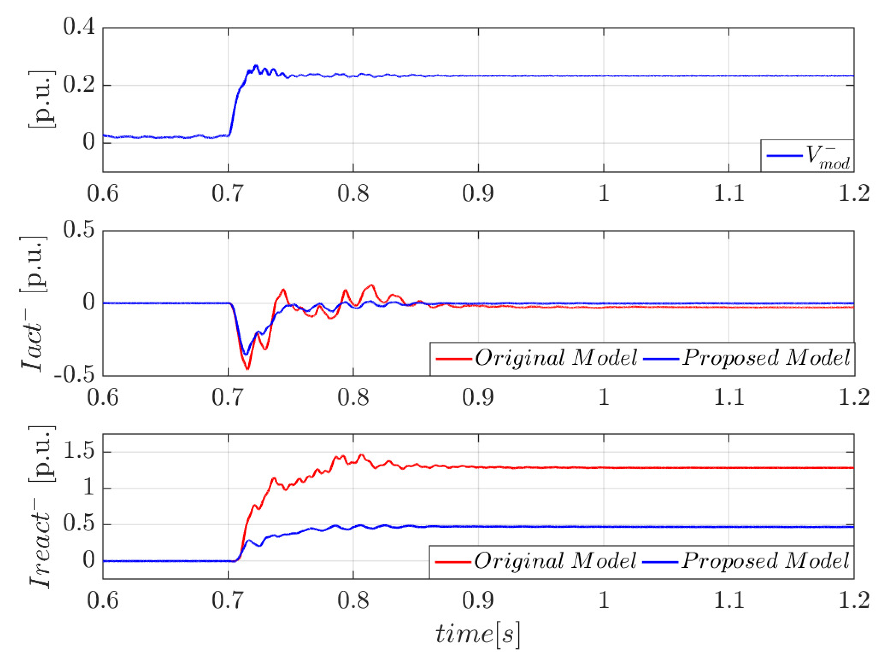
5.4. Comparison between the Original and the Proposed Model
6. Conclusions
Author Contributions
Funding
Data Availability Statement
Conflicts of Interest
Appendix A. RSCAD Parameters

| Parameters | Value | Units |
| DC voltage of the VSC, | 1200 | V |
| Converter rated power, | 2 | MVA |
| Line to line rated voltage (RMS), | 690 | V |
| Filter inductance, | 0.113 | mH |
| Filter resistance, | 0.714 | mΩ |
| Filter capacitance, | 0.5 | mF |
| Nominal frequency, | 50 | Hz |
| Switching frequency, | 3 | kHz |
| Grid inductance, | 56.5 | µH |
| Grid resistance, | 0.357 | µΩ |
| Short-circuit ratio, SCR | 2 | |
| X/R ratio | 10 | |
| : power rating, | 2 | MVA |
| : rated line–line voltage primary, | 20 | kV |
| : rated line–line voltage secondary, | 0.69 | kV |
| : frequency | 50 | Hz |
Appendix B. Control System Parameters
| Parameters | Value | Units |
| Inertia, | 15 | s |
| Damping constant, | 50 | p.u. |
| PSS time constant, | 1.2 | s |
| PSS constant, | 0.01 | |
| PI Gain, | 0.12 | |
| PI Time constant, | 0.01 | s |
| PI Gain, | 0.3 | |
| PI Time constant, | 0.04 | s |
| PI Gain, | −0.5 | |
| PI Time constant, | 0.085 | s |
| PI Gain, | −0.5 | |
| PI Time constant, | 0.085 | s |
| PI Gain, | 1 | |
| PI Time constant, | 0.16 | s |
References
- Christensen, P.; Andersen, G.K.; Seidel, M.; Bolik, S.; Engelken, S.; Knueppel, T.; Krontiris, A.; Wuerflinger, K.; Bülo, T.; Jahn, J.; et al. High Penetration of Power Electronic Interfaced Power Sources and the Potential Contribution of Grid Forming Converters; ENTSO-E 2020; ENTSO: Brussels, Belgium, 2020. [Google Scholar]
- International Renewable Energy Agency (IRENA). Renewable Energy Statistics 2021; IRENA: Abu Dhabi, United Arab Emirates, 2021; ISBN 978-92-9260-356-4. [Google Scholar]
- Matevosyan, J.; Vital, V.; O’Sullivan, J.; Quint, R.; Badrzadeh, B.; Prevost, T.; Quitmann, E.; Ramasubramanian, D.; Urdal, H.; Achilles, S.; et al. Grid-Forming Inverters: Are They the Key for High Renewable Penetration? IEEE Power Energy Mag. 2019, 17, 89–98. [Google Scholar] [CrossRef]
- Rathnayake, D.B.; Akrami, M.; Phurailatpam, C.; Me, S.P.; Hadavi, S.; Jayasinghe, G.; Zabihi, S.; Bahrani, B. Grid Forming Inverter Modeling, Control, and Applications. IEEE Access 2021, 9, 114781–114807. [Google Scholar] [CrossRef]
- Matevosyan, J.; MacDowell, J.; Miller, N.; Badrzadeh, B.; Ramasubramanian, D.; Isaacs, A.; Quint, R.; Quitmann, E.; Pfeiffer, R.; Urdal, H.; et al. A Future With Inverter-Based Resources: Finding Strength From Traditional Weakness. IEEE Power Energy Mag. 2021, 19, 18–28. [Google Scholar] [CrossRef]
- Tielens, P.; Van Hertem, D. The relevance of inertia in power systems. Renew. Sustain. Energy Rev. 2016, 55, 999–1009. [Google Scholar] [CrossRef]
- Rosso, R.; Wang, X.; Liserre, M.; Lu, X.; Engelken, S. Grid-Forming Converters: Control Approaches, Grid-Synchronization, and Future Trends—A Review. IEEE Open J. Ind. Appl. 2021, 2, 93–109. [Google Scholar] [CrossRef]
- Zhang, H.; Xiang, W.; Lin, W.; Wen, J. Grid Forming Converters in Renewable Energy Sources Dominated Power Grid: Control Strategy, Stability, Application, and Challenges. J. Mod. Power Syst. Clean Energy 2021, 9, 1239–1256. [Google Scholar] [CrossRef]
- Chandorkar, M.; Divan, D.; Adapa, R. Control of parallel connected inverters in stand-alone AC supply systems. IEEE Trans. Ind. Appl. 1993, 29, 136–143. [Google Scholar] [CrossRef]
- Hart, P.; Lesieutre, B. Energy function for a grid-tied, droop-controlled inverter. In Proceedings of the 2014 North American Power Symposium (NAPS), Pullman, WA, USA, 7–9 September 2014. [Google Scholar]
- D’Arco, S.; Suul, J.A. Equivalence of Virtual Synchronous Machines and Frequency-Droops for Converter-Based MicroGrids. IEEE Trans. Smart Grid 2013, 5, 394–395. [Google Scholar] [CrossRef]
- Beck, H.-P.; Hesse, R. Virtual synchronous machine. In Proceedings of the 2007 9th International Conference on Electrical Power Quality and Utilisation, Barcelona, Spain, 9–11 October 2007; pp. 1–6. [Google Scholar]
- Driesen, J.; Visscher, K. Virtual synchronous generators. In Proceedings of the 2008 IEEE Power and Energy Society General Meeting—Conversion and Delivery of Electrical Energy in the 21st Century, Pittsburgh, PA, USA, 20–24 July 2008. [Google Scholar]
- Liu, J.; Miura, Y.; Bevrani, H.; Ise, T. Enhanced Virtual Synchronous Generator Control for Parallel Inverters in Microgrids. IEEE Trans. Smart Grid 2017, 8, 2268–2277. [Google Scholar] [CrossRef]
- Zhong, Q.-C.; Nguyen, P.-L.; Ma, Z.; Sheng, W. Self-Synchronized Synchronverters: Inverters Without a Dedicated Synchronization Unit. IEEE Trans. Power Electron. 2014, 29, 617–630. [Google Scholar] [CrossRef]
- Johnson, B.B.; Dhople, S.V.; Hamadeh, A.O.; Krein, P.T. Synchronization of Parallel Single-Phase Inverters with Virtual Oscillator Control. IEEE Trans. Power Electron. 2014, 29, 6124–6138. [Google Scholar] [CrossRef]
- Johnson, B.B.; Dhople, S.V.; Cale, J.L.; Hamadeh, A.O.; Krein, P.T. Oscillator-Based Inverter Control for Islanded Three-Phase Microgrids. IEEE J. Photovoltaics 2014, 4, 387–395. [Google Scholar] [CrossRef]
- Groÿ, D.; Colombino, M.; Brouillon, J.; Dörfler, F. The effect of transmission-line dynamics on grid-forming dispatchable virtualoscillator control. IEEE Trans. Control Netw. Syst. 2019, 6, 1148–1160. [Google Scholar]
- Zubiaga, M.; Cardozo, C.; Prevost, T.; Sanchez-Ruiz, A.; Olea, E.; Izurza, P.; Khan, S.H.; Arza, J. Enhanced TVI for Grid Forming VSC under Unbalanced Faults. Energies 2021, 14, 6168. [Google Scholar] [CrossRef]
- Quispe, J.C.; Orduña, E. Transmission line protection challenges influenced by inverter-based resources: A review. Prot. Control. Mod. Power Syst. 2022, 7, 28. [Google Scholar] [CrossRef]
- Paquette, A.D.; Divan, D.M. Virtual Impedance Current Limiting for Inverters in Microgrids with Synchronous Generators. IEEE Trans. Ind. Appl. 2014, 51, 1630–1638. [Google Scholar] [CrossRef]
- Zarei, S.F.; Mokhtari, H.; Ghasemi, M.A.; Blaabjerg, F. Reinforcing Fault Ride Through Capability of Grid Forming Voltage Source Converters Using an Enhanced Voltage Control Scheme. IEEE Trans. Power Deliv. 2018, 34, 1827–1842. [Google Scholar] [CrossRef]
- Bottrell, N.; Green, T.C. Comparison of Current-Limiting Strategies During Fault Ride-Through of Inverters to Prevent Latch-Up and Wind-Up. IEEE Trans. Power Electron. 2013, 29, 3786–3797. [Google Scholar] [CrossRef]
- Fan, B.; Wang, X. Current-Limiting Control of Grid-Forming Inverters: State-of-the-Art and Open Issues. TechRxiv 2022. [Google Scholar] [CrossRef]
- Gkountaras, A.; Dieckerhoff, S.; Sezi, T. Evaluation of current limiting methods for grid forming inverters in medium voltage microgrids. In Proceedings of the 2015 IEEE Energy Conversion Congress and Exposition (ECCE), Montreal, QC, Canada, 20–24 September 2015; pp. 1223–1230. [Google Scholar]
- Welck, F.; Duckwitz, D.; Gloeckler, C. Influence of virtual impedance on short circuit performance of virtual synchronous machines in the 9-bus system. In Proceedings of the NEIS 2017: Conference on Sustainable Energy Supply and Energy Storage Systems, Hamburg, Germany, 21–22 September 2017; VDE: Frankfurt am Main, Germany, 2017; pp. 1–7. [Google Scholar]
- Glöckler, C.; Duckwitz, D.; Welck, F. Virtual synchronous machine control with virtual resistor for enhanced short circuit capability. In Proceedings of the 2017 IEEE PES Innovative Smart Grid Technologies Conference Europe (ISGT-Europe), Turin, Italy, 26–29 September 2017; pp. 1–6. [Google Scholar]
- Camacho, A.; Castilla, M.; Miret, J.; Guzman, R.; Borrell, A. Reactive Power Control for Distributed Generation Power Plants to Comply with Voltage Limits During Grid Faults. IEEE Trans. Power Electron. 2014, 29, 6224–6234. [Google Scholar] [CrossRef]
- Karimi, H.; Haddadi, A.; Karimi-Ghartemani, M.; Sadabadi, M. A Robust Vector Current Controller with Negative-Sequence Current Capability for Grid-Connected Inverters. Energies 2021, 14, 4549. [Google Scholar] [CrossRef]
- Khan, A.; Ahmad, H.; Ahsan, S.M.; Gulzar, M.M.; Murawwat, S. Coordinated LVRT Support for a PMSG-Based Wind Energy Conversion System Integrated into a Weak AC-Grid. Energies 2021, 14, 6588. [Google Scholar] [CrossRef]
- Baeckeland, N.; Herteleer, B.; Kleemann, M. Modelling fault behaviour of power electronic converters. Int. J. Electr. Power Energy Syst. 2020, 123, 106230. [Google Scholar] [CrossRef]
- Jia, J.; Yang, G.; Nielsen, A.H. A Review on Grid-Connected Converter Control for Short-Circuit Power Provision Under Grid Unbalanced Faults. IEEE Trans. Power Deliv. 2018, 33, 649–661. [Google Scholar] [CrossRef]
- Haddadi, A.; Farantatos, E.; Kocar, I.; Karaagac, U. Impact of Inverter Based Resources on System Protection. Energies 2021, 14, 1050. [Google Scholar] [CrossRef]
- Haddadi, A.; Kocar, I.; Farantatos, E. Impact of Inverter-Based Resources on Protection Schemes Based on Negative Sequence Components; EPRI: Palo Alto, CA, USA, 2019. [Google Scholar]
- Villén, M.T.; Comech, M.P.; Carrasco, E.M.; Hurtado, A.A.P. Influence of Negative Sequence Injection Strategies on Faulted Phase Selector Performance. Energies 2022, 15, 6018. [Google Scholar] [CrossRef]
- VDE_AR_N_4110 Technical Requirements for the Connection and Operation of Customer Installations to the Medium Volt-age Network (TAR Medium Voltage). November 2018. Available online: https://www.vde.com/en/fnn/topics/technical-connection-rules/tcr-for-medium-voltage (accessed on 17 March 2023).
- IPTO. Integration of the Regulation EU 631/2016 into the Greek Regulatory Framework, (Public Consultation Document). Available online: https://www.admie.gr/sites/default/files/diaboyleyseis/attached-files2020/09/Integration_of_the_Regulation_EU_631-2016_into_the_Greek_Regulatory_Framework.pdf (accessed on 17 March 2023).
- Ministerio para la Transición Ecológica y el Reto Demográfico. Orden TED/749/2020, de 16 de Julio, Por La Que Se Establecen Los Requisitos Técnicos Para La Conexión a La Red Necesarios Para La Implementación de Los Códigos de Red de Conexión. 2020. BOE-A-2020-8965. pp. 62406–62458. Available online: https://www.boe.es/eli/es/o/2020/07/16/ted749/con (accessed on 7 July 2022).
- Abubakar, M.; Renner, H.; Schürhuber, R. Development of a Novel Control Scheme for Grid-Following Converter under Asymmetrical Faults. Energies 2023, 16, 1276. [Google Scholar] [CrossRef]
- Abubakar, M.; Akbari, H.; Renner, H. Development of Reference Current Calculation Scheme for Grid-Side Converter during Unbalanced Faults. In Proceedings of the 2022 2nd International Conference on Sustainable Mobility Applications, Renewables and Technology (SMART), Cassino, Italy, 23–25 November 2022; pp. 1–9. [Google Scholar]
- Almeida, V.A.F.; Taranto, G.N.; Marinho, J.M.T. Phasor-domain Dynamic Model of Asymmetric Current Injection Controller for Converter-interfaced Generator. J. Mod. Power Syst. Clean Energy 2021, 9, 1269–1278. [Google Scholar] [CrossRef]
- Taul, M.G.; Wang, X.; Davari, P.; Blaabjerg, F. Current Reference Generation Based on Next-Generation Grid Code Requirements of Grid-Tied Converters During Asymmetrical Faults. IEEE J. Emerg. Sel. Top. Power Electron. 2020, 8, 3784–3797. [Google Scholar] [CrossRef]
- Rodríguez-Amenedo, J.L.; Gómez, S.A.; Zubiaga, M.; Izurza-Moreno, P.; Arza, J.; Fernández, J.D. Grid-Forming Control of Voltage Source Converters Based on the Virtual-Flux Orientation. IEEE Access 2023, 11, 10254–10274. [Google Scholar] [CrossRef]


| Power Generating Module Type | Voltage at the Connection Point | Maximum Capacity |
|---|---|---|
| Type A | ||
| Type B | ||
| Type C | ||
| Type D |
| Cases | ||||
|---|---|---|---|---|
| Cases | ||||||
|---|---|---|---|---|---|---|
| Original Model | ||||
| Proposed Model |
Disclaimer/Publisher’s Note: The statements, opinions and data contained in all publications are solely those of the individual author(s) and contributor(s) and not of MDPI and/or the editor(s). MDPI and/or the editor(s) disclaim responsibility for any injury to people or property resulting from any ideas, methods, instructions or products referred to in the content. |
© 2023 by the authors. Licensee MDPI, Basel, Switzerland. This article is an open access article distributed under the terms and conditions of the Creative Commons Attribution (CC BY) license (https://creativecommons.org/licenses/by/4.0/).
Share and Cite
Dolado Fernández, J.; Eloy-Garcia, J.; Arnaltes, S.; Rodríguez-Amenedo, J.L. Sequence Control Strategy for Grid-Forming Voltage Source Converters Based on the Virtual-Flux Orientation under Balanced and Unbalanced Faults. Energies 2023, 16, 3056. https://doi.org/10.3390/en16073056
Dolado Fernández J, Eloy-Garcia J, Arnaltes S, Rodríguez-Amenedo JL. Sequence Control Strategy for Grid-Forming Voltage Source Converters Based on the Virtual-Flux Orientation under Balanced and Unbalanced Faults. Energies. 2023; 16(7):3056. https://doi.org/10.3390/en16073056
Chicago/Turabian StyleDolado Fernández, Juan, Joaquín Eloy-Garcia, Santiago Arnaltes, and Jose Luis Rodríguez-Amenedo. 2023. "Sequence Control Strategy for Grid-Forming Voltage Source Converters Based on the Virtual-Flux Orientation under Balanced and Unbalanced Faults" Energies 16, no. 7: 3056. https://doi.org/10.3390/en16073056
APA StyleDolado Fernández, J., Eloy-Garcia, J., Arnaltes, S., & Rodríguez-Amenedo, J. L. (2023). Sequence Control Strategy for Grid-Forming Voltage Source Converters Based on the Virtual-Flux Orientation under Balanced and Unbalanced Faults. Energies, 16(7), 3056. https://doi.org/10.3390/en16073056