

Hydrogen Refueling Process: Theory, Modeling, and In-Force Applications


Abstract
1. Introduction
- Acceptable charging times necessary to guarantee a full tank;
- Driving range of more than 500 km;
- Fossil parity, or technical and economic goals equivalent to those of the corresponding technologies based on fossil fuels (e.g., diesel), in order to encourage the adoption of hydrogen technology.
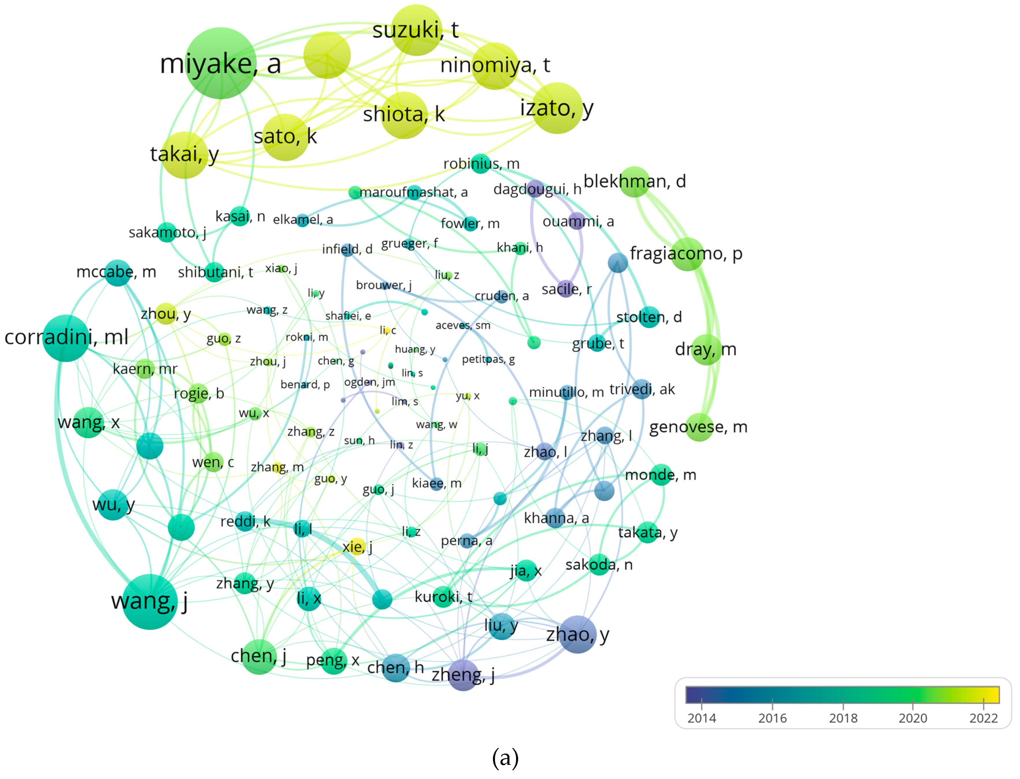
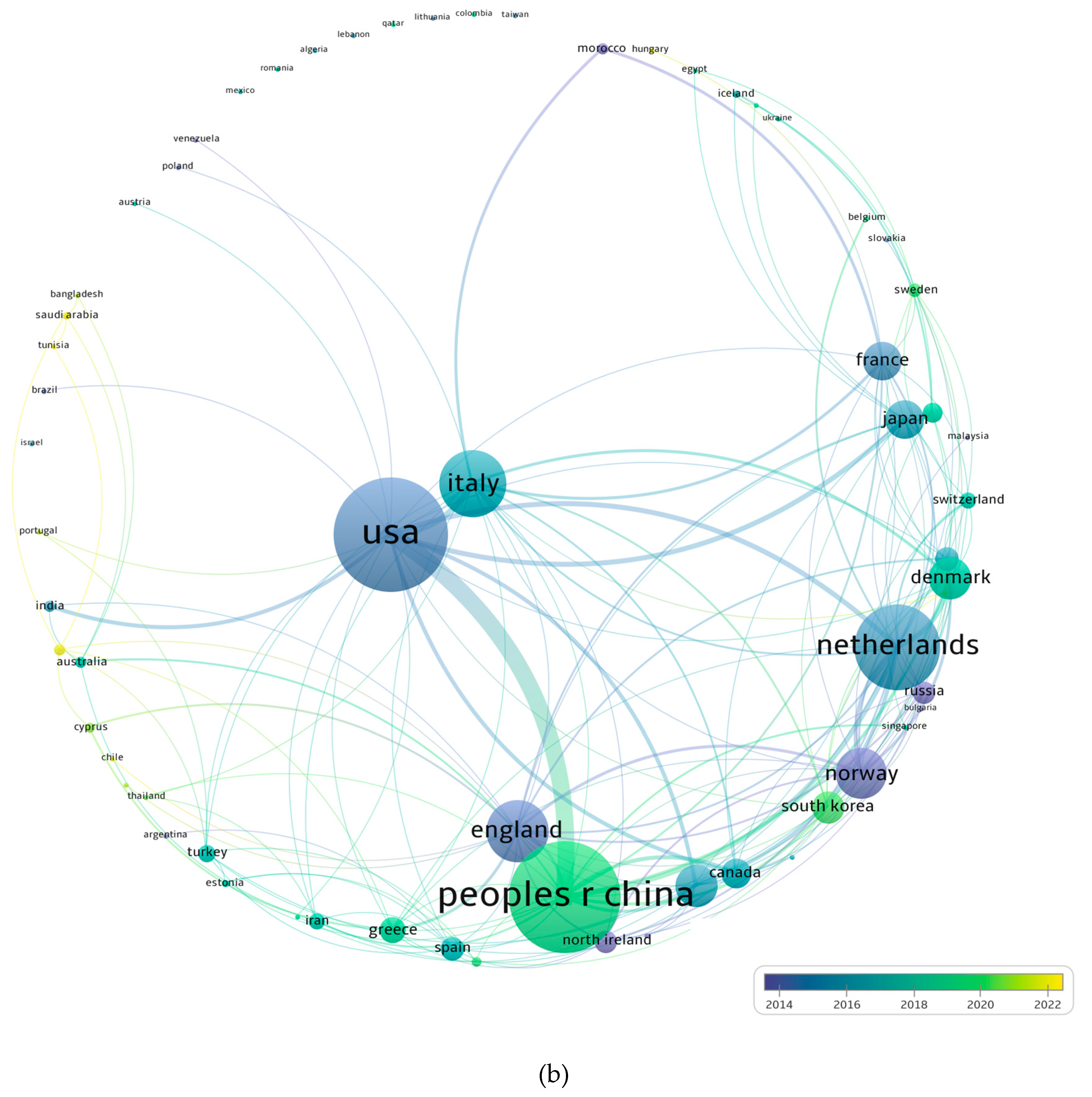
2. Materials and Methods
3. Refueling Process
3.1. Hydrogen Cascading
3.2. Hydrogen Dispensing Line
- Joining the hydrogen fueling station’s dispenser to the fuel cell vehicle.
- Pumping up the dispenser’s pressure to the desired level, usually around 700 bar.
- Allowing the hydrogen to flow from the dispenser into the storage system by opening the fuel cell vehicle’s fill valve.
- Controlling the filling process to check for leaks or other issues and to ensure that the storage system is being filled to the proper pressure level.
- After the storage system is full, shutting off the fuel cell vehicle’s fill valve.
- Cutting the vehicle’s connection to the dispenser and looking for leaks.
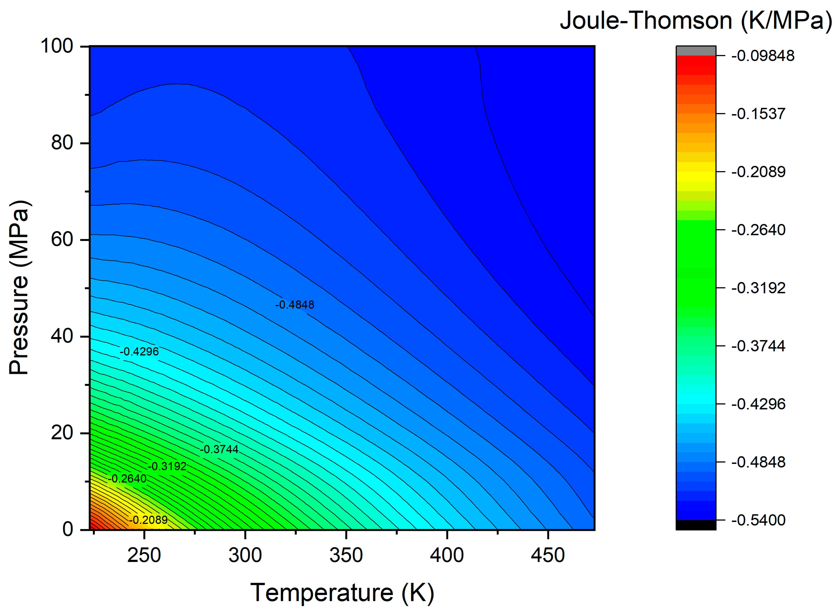
3.3. Hydrogen Pressure Regulator
3.4. Hydrogen Pre-Cooling
- The compressed hydrogen first travels through a heat exchanger.
- The hydrogen cools as a result of the refrigerant absorbing heat from it.
- A compressor is used to increase the refrigerant’s pressure and temperature.
- After passing through a condenser, the heated refrigerant releases its heat to the surrounding air or water.
- To lower its pressure and temperature, the refrigerant is then passed through an expansion valve.
- The process is then repeated with the refrigerant passing once more through the heat exchanger to pick up more heat from the hydrogen.
- Vapor-compression refrigeration is a popular form of cooling technology. It works by compressing a refrigerant, which absorbs heat from the hydrogen and releases it into the surrounding air. With the aid of this technology, hydrogen can be cooled to −40 °C.
- Cryogenic cooling: This method chills hydrogen to extremely low temperatures, usually below −150 °C, using liquefied gases like liquid nitrogen or liquid helium. Larger hydrogen fueling stations based on liquid hydrogen storage could use cryogenic fluids.
- Absorption cooling: This method cools hydrogen via the adoption of absorption chillers.
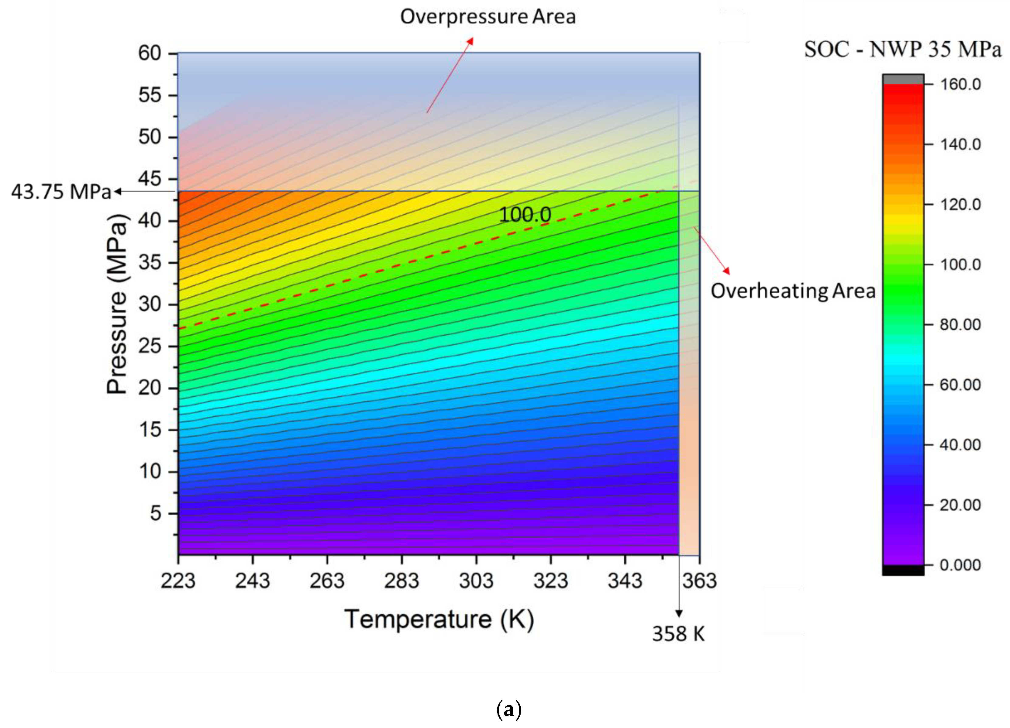
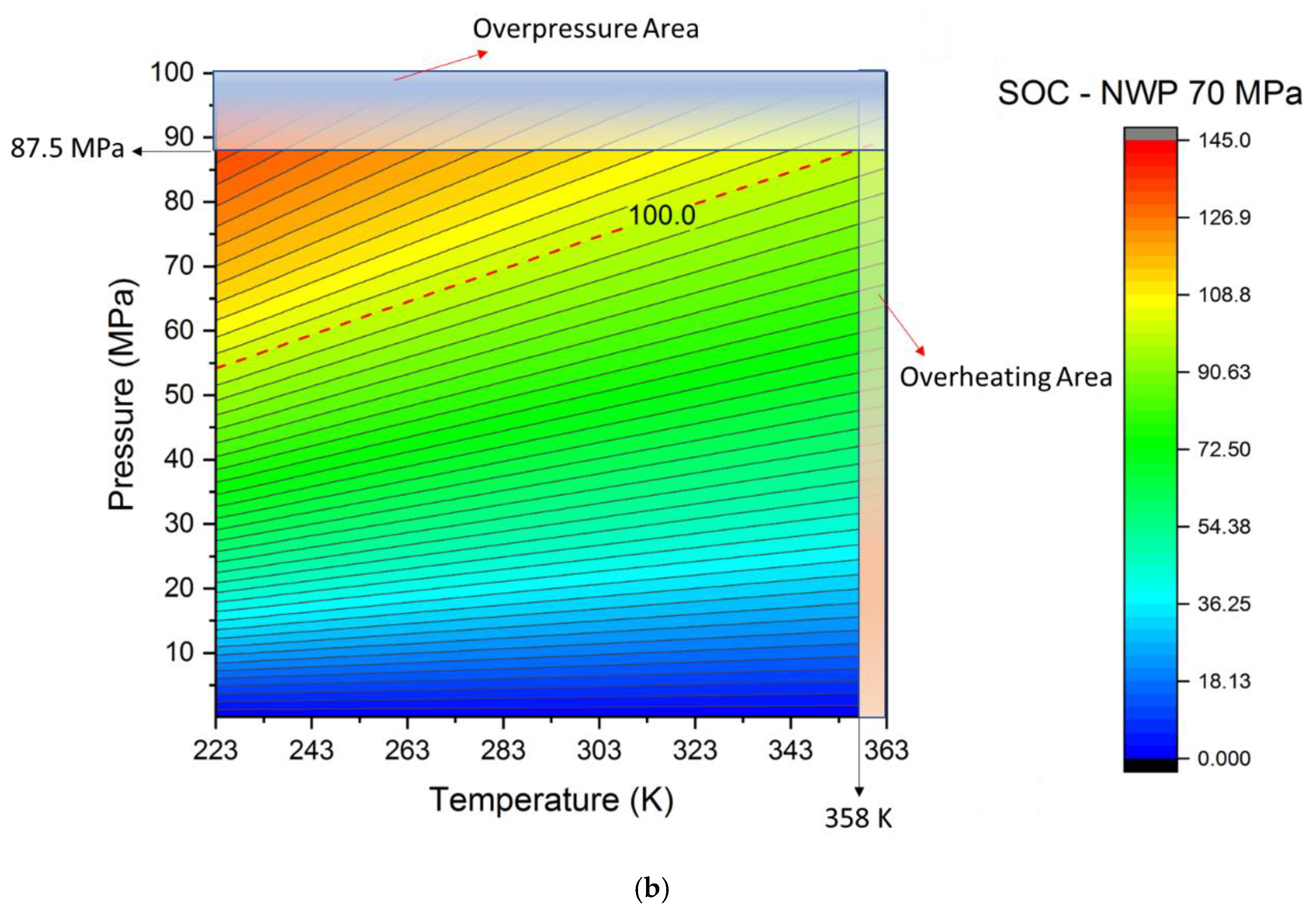
3.5. CCHS Filling
- The heat produced during compression, which may influence the hydrogen temperature level within the tank.
- The negative Joule–Thomson coefficient, which states that as the quantity of pressurized gas entering the tank rises, the temperature rises.
- The materials and wall thickness used to construct hydrogen storage tanks minimize heat transmission, which might affect the temperature increase in the tank.
4. Refuelling Procedures
- Imposing the ramp rate, via the adoption of an APRR. In this case, the pressure profile is monitored and controlled, as described in Equation (13). The mass flow rate dispensed to the vehicle is a non-controlled variable, only monitored. The temperature profile could be either actively monitored and controlled, or only used as a parameter to end the refueling procedure.
- 2.
- Imposing the mass flow rate and monitoring the temperature profile for fast filling. In this configuration, the pressure ramp rate is a non-controlled variable, only monitored. The temperature profile could be either actively monitored and controlled, or only used as a parameter to end the refueling procedure.
- 3.
- A combination of the previous procedures, to be adopted under certain circumstances and for a portion of the refueling process. E.g., imposing the mass flow rate for faster fueling at the beginning and then imposing the pressure ramp rate for avoiding excessive overheating.
5. Conclusions
- Concerning hydrogen storage, the majority of the research efforts are concentrated on establishing the optimal design for cascade hydrogen storage systems with the goal of reducing the amount of energy that is wasted by either the HRP or the irreversibilities.
- In the hydrogen dispensing line, pulsation-free operation, pressure losses, and hydrogen losses are the most critical aspects that must be addressed.
- The Joule–Thomson phenomenon has a predominant effect affecting the temperature level after the pressure regulator.
- Pre-cooling systems are necessary equipment to perform a fast refueling process without overheating the gas. This is especially true for back-to-back refueling processes.
- Modeling and testing CCHS filling have been performed via different methodologies by researchers. The most key findings have been summarized.
- Current refueling procedures consider the imposition of an APRR to perform the filling process.
Author Contributions
Funding
Data Availability Statement
Conflicts of Interest
References
- Hassan, I.A.; Ramadan, H.S.; Saleh, M.A.; Hissel, D. Hydrogen Storage Technologies for Stationary and Mobile Applications: Review, Analysis and Perspectives. Renew. Sustain. Energy Rev. 2021, 149, 111311. [Google Scholar] [CrossRef]
- Kovač, A.; Paranos, M.; Marciuš, D. Hydrogen in Energy Transition: A Review. Int. J. Hydrogen Energy 2021, 46, 10016–10035. [Google Scholar] [CrossRef]
- Cigolotti, V.; Genovese, M.; Fragiacomo, P. Comprehensive Review on Fuel Cell Technology for Stationary Applications as Sustainable and Efficient Poly-Generation Energy Systems. Energies 2021, 14, 4963. [Google Scholar] [CrossRef]
- Genovese, M.; Schlüter, A.; Scionti, E.; Piraino, F.; Corigliano, O.; Fragiacomo, P. Power-to-Hydrogen and Hydrogen-to-X Energy Systems for the Industry of the Future in Europe. Int. J. Hydrogen Energy 2023. [Google Scholar] [CrossRef]
- Fragiacomo, P.; Genovese, M.; Piraino, F.; Corigliano, O.; de Lorenzo, G. Hydrogen-Fuel Cell Hybrid Powertrain: Conceptual Layouts and Current Applications. Machines 2022, 10, 1121. [Google Scholar] [CrossRef]
- Fragiacomo, P.; Piraino, F.; Genovese, M.; Corigliano, O.; Lorenzo, G. de Strategic Overview on Fuel Cell-Based Systems for Mobility and Electrolytic Cells for Hydrogen Production. Procedia Comput. Sci. 2022, 200, 1254–1263. [Google Scholar] [CrossRef]
- Elgowainy, A.; Gaines, L.; Wang, M. Fuel-Cycle Analysis of Early Market Applications of Fuel Cells: Forklift Propulsion Systems and Distributed Power Generation. Int. J. Hydrogen Energy 2009, 34, 3557–3570. [Google Scholar] [CrossRef]
- Lototskyy, M.V.; Tolj, I.; Parsons, A.; Smith, F.; Sita, C.; Linkov, V. Performance of Electric Forklift with Low-Temperature Polymer Exchange Membrane Fuel Cell Power Module and Metal Hydride Hydrogen Storage Extension Tank. J. Power Sources 2016, 316, 239–250. [Google Scholar] [CrossRef]
- Jones, J.; Genovese, A.; Tob-Ogu, A. Hydrogen Vehicles in Urban Logistics: A Total Cost of Ownership Analysis and Some Policy Implications. Renew. Sustain. Energy Rev. 2020, 119, 109595. [Google Scholar] [CrossRef]
- Sagaria, S.; Costa Neto, R.; Baptista, P. Assessing the Performance of Vehicles Powered by Battery, Fuel Cell and Ultra-Capacitor: Application to Light-Duty Vehicles and Buses. Energy Convers. Manag. 2021, 229, 113767. [Google Scholar] [CrossRef]
- Breuer, J.L.; Samsun, R.C.; Stolten, D.; Peters, R. How to Reduce the Greenhouse Gas Emissions and Air Pollution Caused by Light and Heavy Duty Vehicles with Battery-Electric, Fuel Cell-Electric and Catenary Trucks. Environ. Int. 2021, 152, 106474. [Google Scholar] [CrossRef] [PubMed]
- Di Ilio, G.; di Giorgio, P.; Tribioli, L.; Cigolotti, V.; Bella, G.; Jannelli, E. Assessment of a Hydrogen-Fueled Heavy-Duty Yard Truck for Roll-On and Roll-Off Port Operations. In SAE Technical Papers; SAE International: Warrendale PA, USA, 5 September 2021. [Google Scholar]
- Di Ilio, G.; di Giorgio, P.; Tribioli, L.; Bella, G.; Jannelli, E. Preliminary Design of a Fuel Cell/Battery Hybrid Powertrain for a Heavy-Duty Yard Truck for Port Logistics. Energy Convers. Manag. 2021, 243, 114423. [Google Scholar] [CrossRef]
- De las Nieves Camacho, M.; Jurburg, D.; Tanco, M. Hydrogen Fuel Cell Heavy-Duty Trucks: Review of Main Research Topics. Int. J. Hydrogen Energy 2022, 47, 29505–29525. [Google Scholar] [CrossRef]
- Piraino, F.; Fragiacomo, P. A Multi-Method Control Strategy for Numerically Testing a Fuel Cell-Battery-Supercapacitor Tramway. Energy Convers. Manag. 2020, 225, 113481. [Google Scholar] [CrossRef]
- Fragiacomo, P.; Piraino, F. Fuel Cell Hybrid Powertrains for Use in Southern Italian Railways. Int. J. Hydrogen Energy 2019, 44, 27930–27946. [Google Scholar] [CrossRef]
- Samsun, R.C.; Rex, M.; Antoni, L.; Stolten, D. Deployment of Fuel Cell Vehicles and Hydrogen Refueling Station Infrastructure: A Global Overview and Perspectives. Energies 2022, 15, 4975. [Google Scholar] [CrossRef]
- Can Samsun, R.; Antoni, L.; Rex, M.; Stolten, D. Deployment Status of Fuel Cells in Road Transport: 2021 Update; Forschungszentrum Jülich GmbH Zentralbibliothek: Jülich, Germany, 2021. [Google Scholar]
- Genovese, M.; Fragiacomo, P. Hydrogen Refueling Station: Overview of the Technological Status and Research Enhancement. J. Energy Storage 2023, 61, 106758. [Google Scholar] [CrossRef]
- Hydrogen Europe Hydrogen Europe, Committee Votes on AFIR, Maritime Transport. Available online: https://hydrogeneurope.eu/committee-votes-on-afir-maritime-transport/ (accessed on 20 January 2023).
- Kang, J.E.; Brown, T.; Recker, W.W.; Samuelsen, G.S. Refueling Hydrogen Fuel Cell Vehicles with 68 Proposed Refueling Stations in California: Measuring Deviations from Daily Travel Patterns. Int. J. Hydrogen Energy 2014, 39, 3444–3449. [Google Scholar] [CrossRef]
- Muratori, M.; Bush, B.; Hunter, C.; Melaina, M.W. Modeling Hydrogen Refueling Infrastructure to Support Passenger Vehicles. Energies 2018, 11, 1171. [Google Scholar] [CrossRef]
- Pagliaro, M.; Iulianelli, A. Hydrogen Refueling Stations: Safety and Sustainability. Gen. Chem. 2020, 6, 190029. [Google Scholar] [CrossRef]
- Kurtz, J.; Sprik, S.; Bradley, T.H. Review of Transportation Hydrogen Infrastructure Performance and Reliability. Int. J. Hydrogen Energy 2019, 44, 12010–12023. [Google Scholar] [CrossRef]
- Kurtz, J.; Sprik, S.; Peters, M.; Bradley, T.H. Retail Hydrogen Station Reliability Status and Advances. Reliab. Eng. Syst. Saf. 2020, 106823. [Google Scholar] [CrossRef]
- Schneider, J. SAE J2601-Worldwide Hydrogen Fueling Protocol: Status, Standardization & Implementation—SAE Fuel Cell Interface Group Chair, PPT presentation, California Energy Commission, 13 August 2012. 2012.
- Reddi, K.; Elgowainy, A.; Rustagi, N.; Gupta, E. Impact of Hydrogen Refueling Configurations and Market Parameters on the Refueling Cost of Hydrogen. Int. J. Hydrogen Energy 2017, 42, 21855–21865. [Google Scholar] [CrossRef]
- Reddi, K.; Elgowainy, A.; Rustagi, N.; Gupta, E. Impact of Hydrogen SAE J2601 Fueling Methods on Fueling Time of Light-Duty Fuel Cell Electric Vehicles. Int. J. Hydrogen Energy 2017, 42, 16675–16685. [Google Scholar] [CrossRef]
- Research and Market. Global Market for Hydrogen Fueling Stations, 2019; Report “Research and Market”: Dublin, Ireland, 2019. [Google Scholar]
- Wen, C.; He, G. Hydrogen Station Technology Development Review through Patent Analysis. Clean Energy 2018, 2, 29–36. [Google Scholar] [CrossRef]
- Mayyas, A.; Mann, M. Manufacturing Competitiveness Analysis for Hydrogen Refueling Stations. Int. J. Hydrogen Energy 2019, 44, 9121–9142. [Google Scholar] [CrossRef]
- Van Eck, N.J.; Waltman, L. Visualizing Bibliometric Networks. In Measuring Scholarly Impact: Methods and Practice; Ding, Y., Rousseau, R., Wolfram, D., Eds.; Springer International Publishing: Cham, Switzerland, 2014; pp. 285–320. ISBN 978-3-319-10377-8. [Google Scholar]
- VOSviewer. Centre for Science and Technology Studies, Leiden University, The Netherlands. Available online: https://www.vosviewer.com (accessed on 25 January 2023).
- Alazemi, J.; Andrews, J. Automotive Hydrogen Fuelling Stations: An International Review. Renew. Sustain. Energy Rev. 2015, 48, 483–499. [Google Scholar] [CrossRef]
- Apostolou, D.; Xydis, G. A Literature Review on Hydrogen Refuelling Stations and Infrastructure. Current Status and Future Prospects. Renew. Sustain. Energy Rev. 2019, 113, 109292. [Google Scholar] [CrossRef]
- Reddi, K.; Elgowainy, A.; Rustagi, N.; Gupta, E. Techno-Economic Analysis of Conventional and Advanced High-Pressure Tube Trailer Configurations for Compressed Hydrogen Gas Transportation and Refueling. Int. J. Hydrogen Energy 2018, 43, 4428–4438. [Google Scholar] [CrossRef]
- Reddi, K.; Mintz, M.; Elgowainy, A.; Sutherland, E. Challenges and Opportunities of Hydrogen Delivery via Pipeline, Tube-Trailer, LIQUID Tanker and Methanation-Natural Gas Grid. In Hydrogen Science and Engineering: Materials, Processes, Systems and Technology; Wiley Online Library: Hoboken, NJ, USA, 2016; ISBN 9783527674268. [Google Scholar]
- Abdalla, A.M.; Hossain, S.; Nisfindy, O.B.; Azad, A.T.; Dawood, M.; Azad, A.K. Hydrogen Production, Storage, Transportation and Key Challenges with Applications: A Review. Energy Convers. Manag. 2018, 165, 602–627. [Google Scholar] [CrossRef]
- Faye, O.; Szpunar, J.; Eduok, U. A Critical Review on the Current Technologies for the Generation, Storage, and Transportation of Hydrogen. Int. J. Hydrogen Energy 2022, 47, 13771–13802. [Google Scholar] [CrossRef]
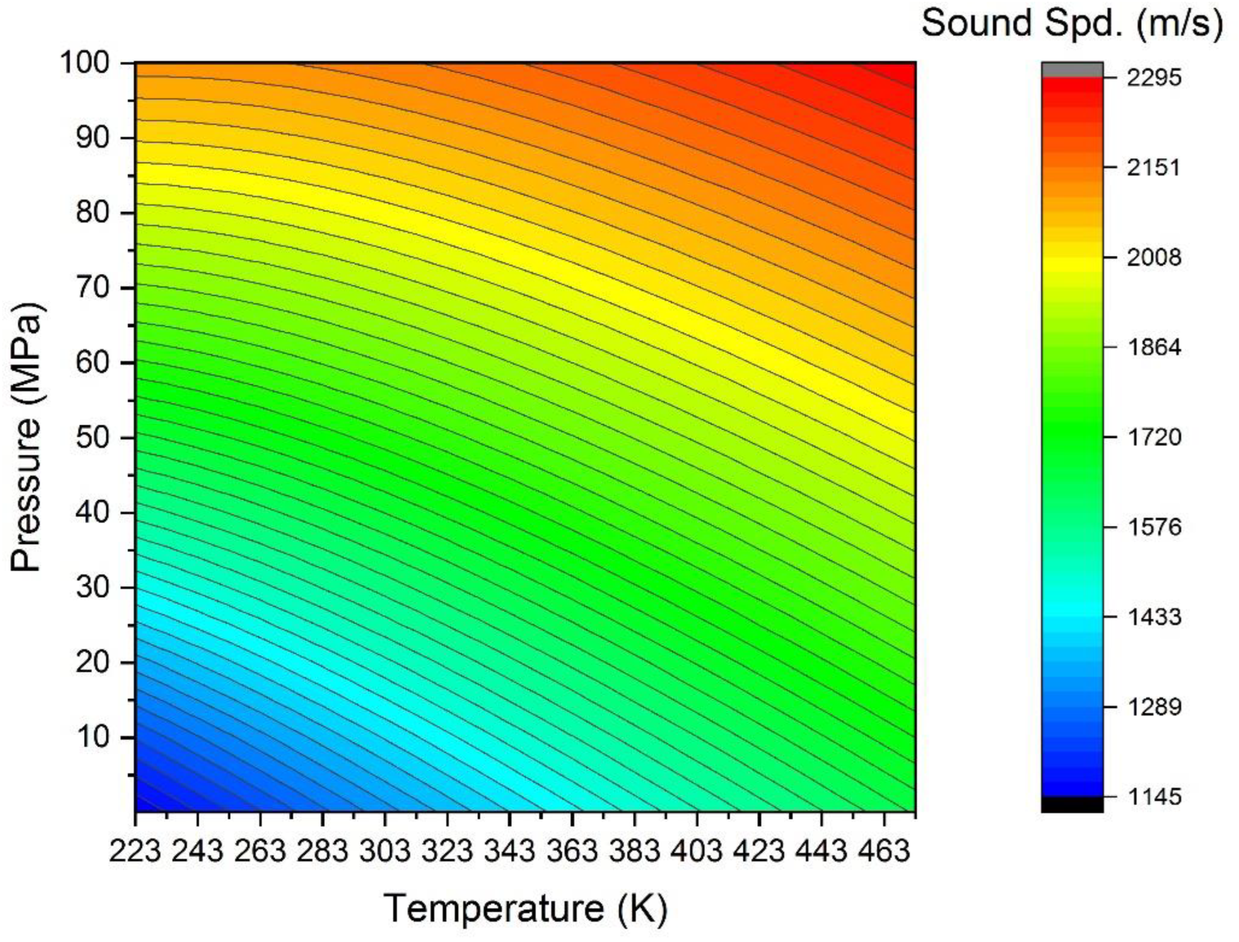
- NIST Chemistry WebBook Thermophysical Properties of Hydrogen. Available online: https://webbook.nist.gov/cgi/fluid.cgi?ID=C1333740&Action=Page (accessed on 15 January 2023).
- Farzaneh-Gord, M.; Deymi-Dashtebayaz, M.; Rahbari, H.R.; Niazmand, H. Effects of Storage Types and Conditions on Compressed Hydrogen Fuelling Stations Performance. Int. J. Hydrogen Energy 2012, 37, 3500–3509. [Google Scholar] [CrossRef]
- Rothuizen, E.; Rokni, M. Optimization of the Overall Energy Consumption in Cascade Fueling Stations for Hydrogen Vehicles. Int. J. Hydrogen Energy 2014, 39, 582–592. [Google Scholar] [CrossRef]
- Elgowainy, A.; Reddi, K.; Sutherland, E.; Joseck, F. Tube-Trailer Consolidation Strategy for Reducing Hydrogen Refueling Station Costs. Int. J. Hydrogen Energy 2014, 39, 20197–20206. [Google Scholar] [CrossRef]
- Reddi, K.; Elgowainy, A.; Sutherland, E. Hydrogen Refueling Station Compression and Storage Optimization with Tube-Trailer Deliveries. Int. J. Hydrogen Energy 2014, 39, 19169–19181. [Google Scholar] [CrossRef]
- Sakoda, N.; Onoue, K.; Kuroki, T.; Shinzato, K.; Kohno, M.; Monde, M.; Takata, Y. Transient Temperature and Pressure Behavior of High-Pressure 100 MPa Hydrogen during Discharge through Orifices. Int. J. Hydrogen Energy 2016, 41, 17169–17174. [Google Scholar] [CrossRef]
- Talpacci, E.; Reuβ, M.; Grube, T.; Cilibrizzi, P.; Gunnella, R.; Robinius, M.; Stolten, D. Effect of Cascade Storage System Topology on the Cooling Energy Consumption in Fueling Stations for Hydrogen Vehicles. Int. J. Hydrogen Energy 2018, 43, 6256–6265. [Google Scholar] [CrossRef]
- Reddi, K.; Elgowainy, A.; Rustagi, N.; Gupta, E. Two-Tier Pressure Consolidation Operation Method for Hydrogen Refueling Station Cost Reduction. Int. J. Hydrogen Energy 2018, 43, 2919–2929. [Google Scholar] [CrossRef]
- Sadi, M.; Deymi-Dashtebayaz, M. Hydrogen Refueling Process from the Buffer and the Cascade Storage Banks to HV Cylinder. Int. J. Hydrogen Energy 2019, 44, 18496–18504. [Google Scholar] [CrossRef]
- Kawano, Y.; Kuroki, T.; Sakoda, N.; Monde, M.; Takata, Y. Thermal Analysis of High-Pressure Hydrogen during the Discharging Process. Int. J. Hydrogen Energy 2019, 44, 27039–27045. [Google Scholar] [CrossRef]
- Rogié, B.; Wen, C.; Kærn, M.R.; Rothuizen, E. Optimisation of the Fuelling of Hydrogen Vehicles Using Cascade Systems and Ejectors. Int. J. Hydrogen Energy 2021, 46, 9567–9579. [Google Scholar] [CrossRef]
- Xiao, L.; Chen, J.; Wu, Y.; Zhang, W.; Ye, J.; Shao, S.; Xie, J. Effects of Pressure Levels in Three-Cascade Storage System on the Overall Energy Consumption in the Hydrogen Refueling Station. Int. J. Hydrogen Energy 2021, 46, 31334–31345. [Google Scholar] [CrossRef]
- Xiao, J.; Bi, C.; Bénard, P.; Chahine, R.; Zong, Y.; Luo, M.; Yang, T. Neural Network Based Optimization for Cascade Filling Process of On-Board Hydrogen Tank. Int. J. Hydrogen Energy 2021, 46, 2936–2951. [Google Scholar] [CrossRef]
- Yu, Y.; Lu, C.; Ye, S.; Hua, Z.; Gu, C. Optimization on Volume Ratio of Three-Stage Cascade Storage System in Hydrogen Refueling Stations. Int. J. Hydrogen Energy 2022, 47, 13430–13441. [Google Scholar] [CrossRef]
- Luo, H.; Xiao, J.; Bénard, P.; Chahine, R.; Yang, T. Multi-Objective Optimization of Cascade Storage System in Hydrogen Refuelling Station for Minimum Cooling Energy and Maximum State of Charge. Int. J. Hydrogen Energy 2022, 47, 10963–10975. [Google Scholar] [CrossRef]
- Caponi, R.; Ferrario, A.M.; Bocci, E.; Bødker, S.; del Zotto, L. Single-Tank Storage versus Multi-Tank Cascade System in Hydrogen Refueling Stations for Fuel Cell Buses. Int. J. Hydrogen Energy 2022, 47, 27633–27645. [Google Scholar] [CrossRef]
- Xu, Z.; Dong, W.; Yang, K.; Zhao, Y.; He, G. Development of Efficient Hydrogen Refueling Station by Process Optimization and Control. Int. J. Hydrogen Energy 2022, 47, 23721–23730. [Google Scholar] [CrossRef]
- Parks, G.; Boyd, R.; Cornish, J.; Remick, R. Hydrogen Station Compression, Storage, and Dispensing Technical Status and Costs: Systems Integration; National Renewable Energy Laboratory: Golden, CO, USA, 2014. [Google Scholar]
- Tahan, M.-R. Recent Advances in Hydrogen Compressors for Use in Large-Scale Renewable Energy Integration. Int. J. Hydrogen Energy 2022, 47, 35275–35292. [Google Scholar] [CrossRef]
- Genovese, M.; Fragiacomo, P. Parametric Technical-Economic Investigation of a Pressurized Hydrogen Electrolyzer Unit Coupled with a Storage Compression System. Renew. Energy 2021, 180, 502–515. [Google Scholar] [CrossRef]
- Wang, T.; Jia, X.; Li, X.; Ren, S.; Peng, X. Thermal-Structural Coupled Analysis and Improvement of the Diaphragm Compressor Cylinder Head for a Hydrogen Refueling Station. Int. J. Hydrogen Energy 2020, 45, 809–821. [Google Scholar] [CrossRef]
- Sdanghi, G.; Maranzana, G.; Celzard, A.; Fierro, V. Review of the Current Technologies and Performances of Hydrogen Compression for Stationary and Automotive Applications. Renew. Sustain. Energy Rev. 2019, 102, 150–170. [Google Scholar] [CrossRef]
- Bhogilla, S.S.; Niyas, H. Design of a Hydrogen Compressor for Hydrogen Fueling Stations. Int. J. Hydrogen Energy 2019, 44, 29329–29337. [Google Scholar] [CrossRef]
- Jia, X.; Chen, J.; Wu, H.; Peng, X. Study on the Diaphragm Fracture in a Diaphragm Compressor for a Hydrogen Refueling Station. Int. J. Hydrogen Energy 2016, 41, 6412–6421. [Google Scholar] [CrossRef]
- Yu, W.; Dianbo, X.; Jianmei, F.; Xueyuan, P. Research on Sealing Performance and Self-Acting Valve Reliability in High-Pressure Oil-Free Hydrogen Compressors for Hydrogen Refueling Stations. Int. J. Hydrogen Energy 2010, 35, 8063–8070. [Google Scholar] [CrossRef]
- Ligen, Y.; Vrubel, H.; Arlettaz, J.; Girault, H. Experimental Correlations and Integration of Gas Boosters in a Hydrogen Refueling Station. Int. J. Hydrogen Energy 2020, 45, 16663–16671. [Google Scholar] [CrossRef]
- Pellegrini, M.; Guzzini, A.; Saccani, C. A Preliminary Assessment of the Potential of Low Percentage Green Hydrogen Blending in the Italian Natural Gas Network. Energies 2020, 13, 5570. [Google Scholar] [CrossRef]
- Fragiacomo, P.; Genovese, M. Numerical Simulations of the Energy Performance of a PEM Water Electrolysis Based High-Pressure Hydrogen Refueling Station. Int. J. Hydrogen Energy 2020, 45, 27457–27470. [Google Scholar] [CrossRef]
- Genovese, M.; Blekhman, D.; Dray, M.; Fragiacomo, P. Improving Chiller Performance and Energy Efficiency in Hydrogen Station Operation by Tuning the Auxiliary Cooling. Int. J. Hydrogen Energy 2022, 47, 2532–2546. [Google Scholar] [CrossRef]
- Wang, Y.; Wang, S.; Decès-Petit, C. Evaluating the Measurement Uncertainty at Hydrogen Refueling Stations Using a Bayesian Non-Parametric Approach. Int. J. Hydrogen Energy 2022, 47, 7892–7901. [Google Scholar] [CrossRef]
- De Huu, M.; Tschannen, M.; Bissig, H.; Stadelmann, P.; Büker, O.; MacDonald, M.; Maury, R.; Neuvonen, P.T.; Petter, H.T.; Rasmussen, K. Design of Gravimetric Primary Standards for Field-Testing of Hydrogen Refuelling Stations. Flow Meas. Instrum. 2020, 73, 101747. [Google Scholar] [CrossRef]
- Büker, O.; Stolt, K.; de Huu, M.; MacDonald, M.; Maury, R. Investigations on Pressure Dependence of Coriolis Mass Flow Meters Used at Hydrogen Refueling Stations. Flow Meas. Instrum. 2020, 76, 101815. [Google Scholar] [CrossRef]
- Haloua, F.; Bacquart, T.; Arrhenius, K.; Delobelle, B.; Ent, H. Metrology for Hydrogen Energy Applications: A Project to Address Normative Requirements. Meas. Sci. Technol. 2018, 29, 034001. [Google Scholar] [CrossRef]
- Maury, R.; Auclercq, C.; Devilliers, C.; de Huu, M.; Büker, O.; MacDonald, M. Hydrogen Refuelling Station Calibration with a Traceable Gravimetric Standard. Flow Meas. Instrum. 2020, 74, 101743. [Google Scholar] [CrossRef]
- Kim, W.; Shentsov, V.; Makarov, D.; Molkov, V. High Pressure Hydrogen Tank Rupture: Blast Wave and Fireball. In Proceedings of the 6th International Conference on Hydrogen Safety, Yokohama, Japan, 19–21 October 2015. [Google Scholar]
- Makarov, D.; Shentsov, V.; Kuznetsov, M.; Molkov, V. Hydrogen Tank Rupture in Fire in the Open Atmosphere: Hazard Distance Defined by Fireball. Hydrogen 2021, 2, 134–146. [Google Scholar] [CrossRef]
- Giannissi, S.G.; Tolias, I.C.; Melideo, D.; Baraldi, D.; Shentsov, V.; Makarov, D.; Molkov, V.; Venetsanos, A.G. On the CFD Modelling of Hydrogen Dispersion at Low-Reynolds Number Release in Closed Facility. Int. J. Hydrogen Energy 2021, 46, 29745–29761. [Google Scholar] [CrossRef]
- Tolias, I.C.; Giannissi, S.G.; Venetsanos, A.G.; Keenan, J.; Shentsov, V.; Makarov, D.; Coldrick, S.; Kotchourko, A.; Ren, K.; Jedicke, O.; et al. Best Practice Guidelines in Numerical Simulations and CFD Benchmarking for Hydrogen Safety Applications. Int. J. Hydrogen Energy 2019, 44, 9050–9062. [Google Scholar] [CrossRef]
- Handa, K.; Oshima, S.; Rembutsu, T. Precooling Temperature Relaxation Technology in Hydrogen Refueling for Fuel-Cell Vehicles. Int. J. Hydrogen Energy 2021, 46, 33511–33522. [Google Scholar] [CrossRef]
- Genovese, M.; Blekhman, D.; Xie, C.; Dray, M.; Fragiacomo, P. Assuring Pulsation-Free Flow in a Directly Pressurized Fuel Delivery at a Retail Hydrogen Station. Int. J. Hydrogen Energy 2018, 43, 16623–16637. [Google Scholar] [CrossRef]
- Genovese, M.; Blekhman, D.; Dray, M.; Fragiacomo, P. Hydrogen Losses in Fueling Station Operation. J Clean Prod 2020, 248, 119266. [Google Scholar] [CrossRef]
- San Marchi, C.; Hecht, E.S.; Ekoto, I.W.; Groth, K.M.; LaFleur, C.; Somerday, B.P.; Mukundan, R.; Rockward, T.; Keller, J.; James, C.W. Overview of the DOE Hydrogen Safety, Codes and Standards Program, Part 3: Advances in Research and Development to Enhance the Scientific Basis for Hydrogen Regulations, Codes and Standards. Int. J. Hydrogen Energy 2017, 42, 7263–7274. [Google Scholar] [CrossRef]
- Buttner, W.J.; Post, M.B.; Burgess, R.; Rivkin, C. An Overview of Hydrogen Safety Sensors and Requirements. Int. J. Hydrogen Energy 2011, 36, 2462–2470. [Google Scholar] [CrossRef]
- Abohamzeh, E.; Salehi, F.; Sheikholeslami, M.; Abbassi, R.; Khan, F. Review of Hydrogen Safety during Storage, Transmission, and Applications Processes. J. Loss Prev. Process Ind. 2021, 72, 104569. [Google Scholar] [CrossRef]
- Zou, Q.; Tian, Y.; Han, F. Prediction of State Property during Hydrogen Leaks from High-Pressure Hydrogen Storage Systems. Int. J. Hydrogen Energy 2019, 44, 22394–22404. [Google Scholar] [CrossRef]
- Mathison, S.; Handa, K.; McGuire, T.; Brown, T.; Goldstein, T.; Johnston, M. Field Validation of the MC Default Fill Hydrogen Fueling Protocol. SAE Int. J. Altern. Powertrains 2015, 4, 130–144. [Google Scholar] [CrossRef]
- Li, J.-Q.; Chen, Y.; Ma, Y.B.; Kwon, J.-T.; Xu, H.; Li, J.-C. A Study on the Joule-Thomson Effect of during Filling Hydrogen in High Pressure Tank. Case Stud. Therm. Eng. 2023, 41, 102678. [Google Scholar] [CrossRef]
- Li, S.; Guo, J.; Lv, X.; Deng, T.; Cao, B.; Wang, J. Research on High-Pressure Hydrogen Pre-Cooling Based on CFD Technology in Fast Filling Process. Processes 2021, 9, 2208. [Google Scholar] [CrossRef]
- Elgowainy, A.; Reddi, K. Hydrogen Fueling Station Pre-Cooling Analysis; 2016 DOE Hydrogen and Fuel Cells Program Annual Merit Review; Department of Energy (DOE): Dallas, TX, USA, 2016.
- Elgowainy, A.; Reddi, K.; Lee, D.Y.; Rustagi, N.; Gupta, E. Techno-Economic and Thermodynamic Analysis of Pre-Cooling Systems at Gaseous Hydrogen Refueling Stations. Int. J. Hydrogen Energy 2017, 42, 29067–29079. [Google Scholar] [CrossRef]
- Chen, J.; Gao, X.; Shao, S.; Hu, H.; Xie, J.; Li, N.; Gao, N. Numerical Investigation of the Vortex Tube Performance in Novel Precooling Methods in the Hydrogen Fueling Station. Int. J. Hydrogen Energy 2021, 46, 5548–5555. [Google Scholar] [CrossRef]
- Piraino, F.; Blekhman, D.; Dray, M.; Fragiacomo, P. Empirically Verified Analysis of Dual Pre-Cooling System for Hydrogen Refuelling Station. Renew Energy 2021, 63, 1612–1625. [Google Scholar] [CrossRef]
- Xiao, R.; Tian, G.; Hou, Y.; Chen, S.; Cheng, C.; Chen, L. Effects of Cooling-Recovery Venting on the Performance of Cryo-Compressed Hydrogen Storage for Automotive Applications. Appl. Energy 2020, 269, 115143. [Google Scholar] [CrossRef]
- Genovese, M.; Blekhman, D.; Dray, M.; Fragiacomo, P. Hydrogen Station in Situ Back-to-Back Fueling Data for Design and Modeling. J. Clean. Prod. 2021, 329, 129737. [Google Scholar] [CrossRef]
- Liu, J.; Ma, H.; Zheng, S.; Zhang, Z.; Zheng, J.; Zhao, Y. Numerical investigation on temperature-rise of on-bus gaseous hydrogen storage cylinder with different thickness of liner and wrapping material. Int. J. Hydrogen Energy 2021, 46, 20607–20620. [Google Scholar] [CrossRef]
- Oh, S.J.; Yoon, J.H.; Jeon, K.S.; Choi, J. A Numerical Study on Characteristics of Heat Transfer in Hydrogen Filling Storage Vessel by Charging Conditions. Int. J. Hydrogen Energy 2022, 47, 25679–25695. [Google Scholar] [CrossRef]
- Li, M.; Bai, Y.; Zhang, C.; Song, Y.; Jiang, S.; Grouset, D.; Zhang, M. Review on the Research of Hydrogen Storage System Fast Refueling in Fuel Cell Vehicle. Int. J. Hydrogen Energy 2019, 44, 10677–10693. [Google Scholar] [CrossRef]
- Guo, J.; Yang, J.; Zhao, Y.; Pan, X.; Zhang, L.; Zhao, L.; Zheng, J. Investigations on Temperature Variation within a Type III Cylinder during the Hydrogen Gas Cycling Test. Int. J. Hydrogen Energy 2014, 39, 13926–13934. [Google Scholar] [CrossRef]
- Simonovski, I.; Baraldi, D.; Melideo, D.; Acosta-Iborra, B. Thermal Simulations of a Hydrogen Storage Tank during Fast Filling. Int. J. Hydrogen Energy 2015, 40, 12560–12571. [Google Scholar] [CrossRef]
- Liu, Y.-L.; Zhao, Y.-Z.; Zhao, L.; Li, X.; Chen, H.; Zhang, L.-F.; Zhao, H.; Sheng, R.-H.; Xie, T.; Hu, D.-H.; et al. Experimental Studies on Temperature Rise within a Hydrogen Cylinder during Refueling. Int. J. Hydrogen Energy 2010, 35, 2627–2632. [Google Scholar] [CrossRef]
- Dicken, C.J.B.; Mérida, W. Measured Effects of Filling Time and Initial Mass on the Temperature Distribution within a Hydrogen Cylinder during Refuelling. J. Power Sources 2007, 165, 324–336. [Google Scholar] [CrossRef]
- Kim, S.C.; Lee, S.H.; Yoon, K.B. Thermal Characteristics during Hydrogen Fueling Process of Type IV Cylinder. Int. J. Hydrogen Energy 2010, 35, 6830–6835. [Google Scholar] [CrossRef]
- Zheng, J.; Ye, J.; Yang, J.; Tang, P.; Zhao, L.; Kern, M. An Optimized Control Method for a High Utilization Ratio and Fast Filling Speed in Hydrogen Refueling Stations. Int. J. Hydrogen Energy 2010, 35, 3011–3017. [Google Scholar] [CrossRef]
- Zhao, L.; Liu, Y.; Yang, J.; Zhao, Y.; Zheng, J.; Bie, H.; Liu, X. Numerical Simulation of Temperature Rise within Hydrogen Vehicle Cylinder during Refueling. Int. J. Hydrogen Energy 2010, 35, 8092–8100. [Google Scholar] [CrossRef]
- Li, Q.; Zhou, J.; Chang, Q.; Xing, W. Effects of Geometry and Inconstant Mass Flow Rate on Temperatures within a Pressurized Hydrogen Cylinder during Refueling. Int. J. Hydrogen Energy 2012, 37, 6043–6052. [Google Scholar] [CrossRef]
- Olmos, F.; Manousiouthakis, V.I. Gas Tank Fill-up in Globally Minimum Time: Theory and Application to Hydrogen. Int. J. Hydrogen Energy 2014, 39, 12138–12157. [Google Scholar] [CrossRef]
- Zheng, J.; Guo, J.; Yang, J.; Zhao, Y.; Zhao, L.; Pan, X.; Ma, J.; Zhang, L. Experimental and Numerical Study on Temperature Rise within a 70 MPa Type III Cylinder during Fast Refueling. Int. J. Hydrogen Energy 2013, 38, 10956–10962. [Google Scholar] [CrossRef]
- Rothuizen, E.; Mérida, W.; Rokni, M.; Wistoft-Ibsen, M. Optimization of Hydrogen Vehicle Refueling via Dynamic Simulation. Int. J. Hydrogen Energy 2013, 38, 4221–4231. [Google Scholar] [CrossRef]
- Suryan, A.; Kim, H.D.; Setoguchi, T. Comparative Study of Turbulence Models Performance for Refueling of Compressed Hydrogen Tanks. Int. J. Hydrogen Energy 2013, 38, 9562–9569. [Google Scholar] [CrossRef]
- Ruffio, E.; Saury, D.; Petit, D. Thermodynamic Analysis of Hydrogen Tank Filling. Effects of Heat Losses and Filling Rate Optimization. Int. J. Hydrogen Energy 2014, 39, 12701–12714. [Google Scholar] [CrossRef]
- Wang, G.; Zhou, J.; Hu, S.; Dong, S.; Wei, P. Investigations of Filling Mass with the Dependence of Heat Transfer during Fast Filling of Hydrogen Cylinders. Int. J. Hydrogen Energy 2014, 39, 4380–4388. [Google Scholar] [CrossRef]
- Ortiz Cebolla, R.; Acosta, B.; de Miguel, N.; Moretto, P. Effect of Precooled Inlet Gas Temperature and Mass Flow Rate on Final State of Charge during Hydrogen Vehicle Refueling. Int. J. Hydrogen Energy 2015, 40, 4698–4706. [Google Scholar] [CrossRef]
- Bourgeois, T.; Ammouri, F.; Weber, M.; Knapik, C. Evaluating the Temperature inside a Tank during a Filling with Highly-Pressurized Gas. Int. J. Hydrogen Energy 2015, 40, 11748–11755. [Google Scholar] [CrossRef]
- De Miguel, N.; Acosta, B.; Baraldi, D.; Melideo, R.; Ortiz Cebolla, R.; Moretto, P. The Role of Initial Tank Temperature on Refuelling of On-Board Hydrogen Tanks. Int. J. Hydrogen Energy 2016, 41, 8606–8615. [Google Scholar] [CrossRef]
- de Miguel, N.; Acosta, B.; Moretto, P.; Ortiz Cebolla, R. Influence of the Gas Injector Configuration on the Temperature Evolution during Refueling of On-Board Hydrogen Tanks. Int. J. Hydrogen Energy 2016, 41, 19447–19454. [Google Scholar] [CrossRef]
- Xiao, J.; Bénard, P.; Chahine, R. Charge-Discharge Cycle Thermodynamics for Compression Hydrogen Storage System. Int. J. Hydrogen Energy 2016, 41, 5531–5539. [Google Scholar] [CrossRef]
- Xiao, J.; Wang, X.; Bénard, P.; Chahine, R. Determining Hydrogen Pre-Cooling Temperature from Refueling Parameters. Int. J. Hydrogen Energy 2016, 41, 16316–16321. [Google Scholar] [CrossRef]
- Cheng, J.; Xiao, J.; Bénard, P.; Chahine, R. Estimation of Final Hydrogen Temperatures During Refueling 35 MPa and 70 MPa Tanks. Energy Procedia 2017, 105, 1363–1369. [Google Scholar] [CrossRef]
- Wang, X.; Xiao, J.; Bénard, P.; Chahine, R. Final Hydrogen Mass Determined from Refueling Parameters. Energy Procedia 2017, 105, 1370–1375. [Google Scholar] [CrossRef]
- Xiao, J.; Bénard, P.; Chahine, R. Estimation of Final Hydrogen Temperature from Refueling Parameters. Int. J. Hydrogen Energy 2017, 42, 7521–7528. [Google Scholar] [CrossRef]
- Bourgeois, T.; Brachmann, T.; Barth, F.; Ammouri, F.; Baraldi, D.; Melideo, D.; Acosta-Iborra, B.; Zaepffel, D.; Saury, D.; Lemonnier, D. Optimization of Hydrogen Vehicle Refuelling Requirements. Int. J. Hydrogen Energy 2017, 42, 13789–13809. [Google Scholar] [CrossRef]
- Kuroki, T.; Sakoda, N.; Shinzato, K.; Monde, M.; Takata, Y. Dynamic Simulation for Optimal Hydrogen Refueling Method to Fuel Cell Vehicle Tanks. Int. J. Hydrogen Energy 2018, 43, 5714–5721. [Google Scholar] [CrossRef]
- Kuroki, T.; Sakoda, N.; Shinzato, K.; Monde, M.; Takata, Y. Prediction of Transient Temperature of Hydrogen Flowing from Pre-Cooler of Refueling Station to Inlet of Vehicle Tank. Int. J. Hydrogen Energy 2018, 43, 1846–1854. [Google Scholar] [CrossRef]
- Xiao, J.; Cheng, J.; Wang, X.; Bénard, P.; Chahine, R. Final Hydrogen Temperature and Mass Estimated from Refueling Parameters. Int. J. Hydrogen Energy 2018, 43, 22409–22418. [Google Scholar] [CrossRef]
- Xiao, J.; Wang, X.; Zhou, X.; Bénard, P.; Chahine, R. A Dual Zone Thermodynamic Model for Refueling Hydrogen Vehicles. Int. J. Hydrogen Energy 2019, 44, 8780–8790. [Google Scholar] [CrossRef]
- Melideo, D.; Baraldi, D.; de Miguel Echevarria, N.; Acosta Iborra, B. Effects of Some Key-Parameters on the Thermal Stratification in Hydrogen Tanks during the Filling Process. Int. J. Hydrogen Energy 2019, 44, 13569–13582. [Google Scholar] [CrossRef]
- Sapre, S.; Pareek, K.; Rohan, R.; Singh, P.K. H2 Refueling Assessment of Composite Storage Tank for Fuel Cell Vehicle. Int. J. Hydrogen Energy 2019, 44, 23699–23707. [Google Scholar] [CrossRef]
- Zhou, X.; Yang, T.; Xiao, J.; Bénard, P.; Chahine, R. Estimation of Filling Time for Compressed Hydrogen Refueling. Energy Procedia 2019, 158, 1897–1903. [Google Scholar] [CrossRef]
- Wang, L.; Ye, F.; Xiao, J.; Bénard, P.; Chahine, R. Heat Transfer Analysis for Fast Filling of On-Board Hydrogen Tank. Energy Procedia 2019, 158, 1910–1916. [Google Scholar] [CrossRef]
- Liu, J.; Zheng, S.; Zhang, Z.; Zheng, J.; Zhao, Y. Numerical Study on the Fast Filling of On-Bus Gaseous Hydrogen Storage Cylinder. Int. J. Hydrogen Energy 2020, 45, 9241–9251. [Google Scholar] [CrossRef]
- Jiang, Y.; Wei, S.T.; Xu, P. Influences of Filling Process on the Thermal-Mechanical Behavior of Composite Overwrapped Pressure Vessel for Hydrogen. Int. J. Hydrogen Energy 2020, 45, 23093–23102. [Google Scholar] [CrossRef]
- Wang, Y.; Decès-Petit, C. Predicting Fueling Process on Hydrogen Refueling Stations Using Multi-Task Machine Learning. Int. J. Hydrogen Energy 2020, 45, 32743–32752. [Google Scholar] [CrossRef]
- Deng, S.; Xiao, J.; Bénard, P.; Chahine, R. Determining Correlations between Final Hydrogen Temperature and Refueling Parameters from Experimental and Numerical Data. Int. J. Hydrogen Energy 2020, 45, 20525–20534. [Google Scholar] [CrossRef]
- Wen, C.; Rogie, B.; Kærn, M.R.; Rothuizen, E. A First Study of the Potential of Integrating an Ejector in Hydrogen Fuelling Stations for Fuelling High Pressure Hydrogen Vehicles. Appl. Energy 2020, 260, 113958. [Google Scholar] [CrossRef]
- Rothuizen, E.; Elmegaard, B.; Rokni, M. Dynamic Simulation of the Effect of Vehicle-Side Pressure Loss of Hydrogen Fueling Process. Int. J. Hydrogen Energy 2020, 45, 9025–9038. [Google Scholar] [CrossRef]
- Sapre, S.; Vyas, M.; Pareek, K. Impact of Refueling Parameters on Storage Density of Compressed Hydrogen Storage Tank. Int. J. Hydrogen Energy 2021, 46, 16685–16692. [Google Scholar] [CrossRef]
- Caponi, R.; Monforti Ferrario, A.; Bocci, E.; Valenti, G.; della Pietra, M. Thermodynamic Modeling of Hydrogen Refueling for Heavy-Duty Fuel Cell Buses and Comparison with Aggregated Real Data. Int. J. Hydrogen Energy 2021, 46, 18630–18643. [Google Scholar] [CrossRef]
- Kuroki, T.; Nagasawa, K.; Peters, M.; Leighton, D.; Kurtz, J.; Sakoda, N.; Monde, M.; Takata, Y. Thermodynamic Modeling of Hydrogen Fueling Process from High-Pressure Storage Tank to Vehicle Tank. Int. J. Hydrogen Energy 2021, 46, 22004–22017. [Google Scholar] [CrossRef]
- Li, H.; Lyu, Z.; Liu, Y.; Han, M.; Li, H. The Effects of Infill on Hydrogen Tank Temperature Distribution during Fast Fill. Int. J. Hydrogen Energy 2021, 46, 10396–10410. [Google Scholar] [CrossRef]
- Bai, Y.; Zhang, C.; Duan, H.; Jiang, S.; Zhou, Z.; Grouset, D.; Zhang, M.; Ye, X. Modeling and Optimal Control of Fast Filling Process of Hydrogen to Fuel Cell Vehicle. J. Energy Storage 2021, 35, 102306. [Google Scholar] [CrossRef]
- Wu, X.; Liu, J.; Shao, J.; Deng, G. Fast Filling Strategy of Type III On-Board Hydrogen Tank Based on Time-Delayed Method. Int. J. Hydrogen Energy 2021, 46, 29288–29296. [Google Scholar] [CrossRef]
- Wang, Y.; Wang, S.; Decès-Petit, C. Less Is More: Robust Prediction for Fueling Processes on Hydrogen Refueling Stations. Int. J. Hydrogen Energy 2022, 47, 28993–29005. [Google Scholar] [CrossRef]
- Kawatsu, K.; Suzuki, T.; Shiota, K.; Izato, Y.; Komori, M.; Sato, K.; Takai, Y.; Ninomiya, T.; Miyake, A. Dynamic Physical Model of Japanese Hydrogen Refueling Stations for Quantitative Trade-off Study between Benefit and Risk. Int. J. Hydrogen Energy 2022. [Google Scholar] [CrossRef]
- Chen, J.; Xiao, L.; Wu, Y.; Gao, X.; Chen, H.; Xie, J.; Shao, S. Dynamic Simulation of the Potential of Integrating a Turbo-Expander in a Hydrogen Refueling Station. Appl. Therm. Eng. 2022, 202, 117889. [Google Scholar] [CrossRef]
- Park, B.H.; Chae, C.K. Development of Correlation Equations on Hydrogen Properties for Hydrogen Refueling Process by Machine Learning Approach. Int. J. Hydrogen Energy 2022, 47, 4185–4195. [Google Scholar] [CrossRef]
- Li, J.-Q.; Li, J.-C.L.; Park, K.; Kwon, J.-T. Investigation on the Changes of Pressure and Temperature in High Pressure Filling of Hydrogen Storage Tank. Case Stud. Therm. Eng. 2022, 37, 102143. [Google Scholar] [CrossRef]
- Deng, S.; Li, F.; Luo, H.; Yang, T.; Ye, F.; Chahine, R.; Xiao, J. Lumped Parameter Modeling of SAE J2601 Hydrogen Fueling Tests. Sustainability 2023, 15, 1448. [Google Scholar] [CrossRef]
- Genovese, M.; Cigolotti, V.; Jannelli, E.; Fragiacomo, P. Current Standards and Configurations for the Permitting and Operation of Hydrogen Refueling Stations. Int. J. Hydrogen Energy 2023. [Google Scholar] [CrossRef]
- Society of Automotive Engineers (SAE) SAE J2601(2016): Fueling Protocols for Light Duty Gaseous Hydrogen Surface Vehicles; SAE International Headquarters 400 Commonwealth Drive: Warrendale, PA, USA, 2016.
- Maus, S.; Hapke, J.; Ranong, C.N.; Wüchner, E.; Friedlmeier, G.; Wenger, D. Filling Procedure for Vehicles with Compressed Hydrogen Tanks. Int. J. Hydrogen Energy 2008, 33, 4612–4621. [Google Scholar] [CrossRef]
- Wang, X.; Fu, J.; Liu, Z.; Liu, J. Review of Researches on Important Components of Hydrogen Supply Systems and Rapid Hydrogen Refueling Processes. Int. J. Hydrogen Energy 2023, 48, 1904–1929. [Google Scholar] [CrossRef]
- Ku, A.Y.; Reddi, K.; Elgowainy, A.; McRobie, J.; Li, J. Liquid Pump-Enabled Hydrogen Refueling System for Medium and Heavy Duty Fuel Cell Vehicles: Station Design and Technoeconomic Assessment. Int. J. Hydrogen Energy 2022, 47, 25486–25498. [Google Scholar] [CrossRef]
- Apostolou, D. Refuelling Scenarios of a Light Urban Fuel Cell Vehicle with Metal Hydride Hydrogen Storage. Comparison with Compressed Hydrogen Storage Counterpart. Int. J. Hydrogen Energy 2021, 46, 39509–39522. [Google Scholar] [CrossRef]
- Li, J.; Youn, E.; Ramteke, A.; McRobie, J.; Hansen, E.; Hall, C.; Kratschmar, K.; Prakash, A.; Conrad, K.; Ku, A.Y. Liquid Pump-Enabled Hydrogen Refueling System for Heavy Duty Fuel Cell Vehicles: Fuel Cell Bus Refueling Demonstration at Stark Area Regional Transit Authority (SARTA). Int. J. Hydrogen Energy 2021, 46, 38575–38587. [Google Scholar] [CrossRef]
- PRHYDE Project on Heavy-Duty Hydrogen Refueling Protocol. Fuel Cells Bulletin 2020, 2020, 8–9. [CrossRef]
- LaChance, J.; Tchouvelev, A.; Ohi, J. Risk-Informed Process and Tools for Permitting Hydrogen Fueling Stations. Int. J. Hydrogen Energy 2009, 34, 5855–5861. [Google Scholar] [CrossRef]
- Böhm, M.; Fernández Del Rey, A.; Pagenkopf, J.; Varela, M.; Herwartz-Polster, S.; Nieto Calderón, B. Review and Comparison of Worldwide Hydrogen Activities in the Rail Sector with Special Focus on On-Board Storage and Refueling Technologies. Int. J. Hydrogen Energy 2022, 47, 38003–38017. [Google Scholar] [CrossRef]
- Petitpas, G.; Aceves, S.M.; Gupta, N. Vehicle Refueling with Liquid Hydrogen Thermal Compression. Int. J. Hydrogen Energy 2012, 37, 11448–11457. [Google Scholar] [CrossRef]
- Petitpas, G.; Moreno-Blanco, J.; Espinosa-Loza, F.; Aceves, S.M. Rapid High Density Cryogenic Pressure Vessel Filling to 345 Bar with a Liquid Hydrogen Pump. Int. J. Hydrogen Energy 2018, 43, 19547–19558. [Google Scholar] [CrossRef]
- Charolais, A.; Ammouri, F.; Vyazmina, E.; Werlen, É.; Harris, A. Safety Watchdog for Universally Safe Gaseous High Pressure Hydrogen Fillings. Int. J. Hydrogen Energy 2021, 46, 16019–16029. [Google Scholar] [CrossRef]
- Striednig, M.; Brandstätter, S.; Sartory, M.; Klell, M. Thermodynamic Real Gas Analysis of a Tank Filling Process. Int. J. Hydrogen Energy 2014, 39, 8495–8509. [Google Scholar] [CrossRef]
- Moreno-Blanco, J.; Camacho, G.; Valladares, F.; Aceves, S.M. The Cold High-Pressure Approach to Hydrogen Delivery. Int. J. Hydrogen Energy 2020, 45, 27369–27380. [Google Scholar] [CrossRef]
- Petitpas, G.; Aceves, S.M. Liquid Hydrogen Pump Performance and Durability Testing through Repeated Cryogenic Vessel Filling to 700 Bar. Int. J. Hydrogen Energy 2018, 43, 18403–18420. [Google Scholar] [CrossRef]


| Database | Search | Results |
|---|---|---|
| WoS | ((TI = ((hydrogen AND (refuelling OR refuelling OR fueling OR fuelling) AND station AND (modelling OR modeling OR experimental)))) OR AB = ((hydrogen AND (refuelling OR refueling OR fueling OR fuelling) AND station AND (modelling OR modeling OR experimental)))) OR AK = ((hydrogen AND (refuelling OR refueling OR fueling OR fuelling) AND station AND (modelling OR modeling OR experimental))) | 548 |
| Scopus | (TITLE-ABS-KEY (hydrogen AND (refuelling OR refueling OR fueling OR fuelling) AND station AND (modelling OR modeling OR experimental))) | 244 |
| Authors | Year | Main Finding |
|---|---|---|
| Farzaneh-Gord et al. [41] | 2012 | A single pressure-level storage system requires around 66% less time than the cascade storage system to raise the vehicle CHSS to an ultimate pressure of 35 MPa but has higher entropy generation and therefore higher irreversibilities. |
| Rothuizen and Rokni [42] | 2014 | Cascading from three/four tanks with different pressure levels can reduce HRP energy consumption. |
| Elgowainy et al. [43] | 2014 | The compression cost at an HRS may be cut by approximately 60%, and the station’s original capital expenditure can be reduced by around 40%, thanks to a consolidation method for a high-pressure (250-bar) tube-trailer. |
| Reddi et al. [44] | 2014 | The cost of refueling may also be decreased by lowering the tube trailer cut-off pressure for first vehicle refueling and raising the trailer’s return pressure, particularly in early markets when the refueling stations will be greatly underused. |
| Sakoda et al. [45] | 2016 | Analysis on the dynamic temperature and pressure levels of high-pressure hydrogen at 100 MPa in a 1-L tank that is released via 0.1-mm- and 0.2-mm-diameter orifices that resemble fractures. |
| Talpacci et al. [46] | 2018 | At ambient temperature, a ratio of 0.12 between low-pressure and high-pressure buffer tanks guarantees the optimal configuration for low energy consumption at the hydrogen chiller. |
| Reddi et al. [47] | 2018 | Thanks to the development of two-tier “pressure consolidation” of supplied tube-trailers (or comparable supply storage), the throughput at HRSs has been increased. |
| Sadi and Deymi-Dashtebayaz [48] | 2019 | A comparison of buffer and cascade storage banks revealed that employing a buffer storage bank results in a 200-s reduction in refueling time. However, the buffer storage system has a larger energy need for gas storage. |
| Kawano et al. [49] | 2019 | Experimental and numerical analyses have been used to examine the heat transfer properties and vessel state changes that occur during the discharge phase. |
| Rogié et al. [50] | 2021 | Application of ejectors that replace expansion valves in HPR. |
| Xiao et al. [51] | 2021 | Operation with three storage systems allows an energy consumption reduction of 34%. |
| Xiao et al. [52] | 2021 | The research demonstrates that an on-board storage tank may be successfully refueled using a cascade filling method with a constant average pressure ramp rate (APRR), which may successfully minimize energy consumption by roughly 2.5% for charging periods under 183 s. |
| Yu et al. [53] | 2022 | The best volume ratio for a stationary storage capacity of 150 kg is 4-3-3, while that for a stationary storage capacity of 600 kg is 1-5-4. |
| Luo et al. [54] | 2022 | Choosing the correct starting pressure and capacity of cascade storage tanks may minimize cooling energy usage by up to 11%. |
| Caponi et al. [55] | 2022 | 10% less energy is needed for compression if a cascade procedure is applied. |
| Xu et al. [56] | 2022 | By alternating between the three banks in the sequence of decreasing pressure, a unique control mechanism for cascade replenishment was established. The findings suggest that this approach increases the daily refueling capacity of HRS by 5%. |
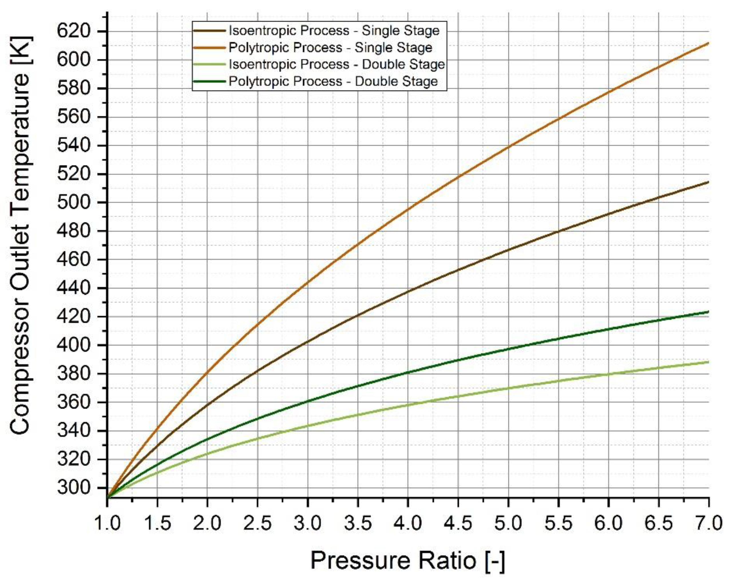
| Parameter | Value |
|---|---|
| Isoentropic Coefficient, [-] | 1.407 [66] |
| Polytropic Coefficient, n [-] | 1.609 [67] |
| Initial Temperature [K] | 293 |
| Maximum Pressure Ratio [-] | 7 |
| Component | Thermal Mass [kJ/kg] |
|---|---|
| Pipe | 0.56–1.64 |
| Hose, Nozzle and Breakaway | 2.71–3.14 |
| Tank Material | Density (kg/m3) | Specific Heat (J/(kg·K)) | Thermal Conductivity (W/(m·K)) |
|---|---|---|---|
| Aluminum liner | 2700–2730 | 902–900- | 167–238 |
| High-density polyethylene liner | 952 | 2090 | 0.3–0.42 |
| Carbon fiber/epoxy composite laminate | 1513–1494 | 920–938 | 3.72–1 |
| Glass fiber/epoxy composite laminate | 2051 | 878.4 | 0.133 |
| Steel | 8030 | 502.48 | 16.27 |
| Authors | Year | Methods | Main Finding |
|---|---|---|---|
| Dicken and Mérida [100] | 2007 | Experimental analyses | Significant temperature variations were induced by the experimental settings with larger ratios of final to beginning mass. The highest rates of temperature increase, however, were produced by the lowest ratios. Due to buoyancy effects at lower gas input velocities, longer fill periods resulted in lower final average gas temperatures (relative to shorter fills) and a temperature field with substantial vertical stratification. |
| Kim et al. [101] | 2010 | CFD analyses | Analyses of the thermal flow characteristics of hydrogen filling and suggestions that further work needs to be done to ensure the safety of a type IV cylinder during filling procedures. |
| Zheng et al. [102] | 2010 | Multi-objective Optimization | In order to accomplish both rapid refueling and high utilization, a multi-objective iterative optimization model has been developed, and an optimization technique for the filling process has been provided. |
| Liu et al. [99] | 2010 | Experimental analyses | During the filling process, the temperature within the cylinder rises nonlinearly, with the caudal area seeing the highest temperature rise at the cylinder interface. |
| Zhao et al. [103] | 2010 | CFD analyses and experimental activities | As the filling rate and ambient temperature rise, the maximum temperature rises as well, whereas as the starting pressure rises, it decreases. |
| Li et al. [104] | 2012 | CFD analyses | Higher temperature increase is the effect of smaller inlet diameter, while refueling with a higher flow rate results in a smaller temperature increase. |
| Olmos and Manousiouthakis [105] | 2013 | Thermodynamic Model | Based on thermodynamics and transport principles, a new mathematical model captures hydrogen pressure, temperature, and molar volume changes during the refueling process. |
| Zheng et al. [106] | 2013 | CFD analyses and experimental activities | The findings indicate that the final hydrogen temperature reduces almost linearly when starting pressure is increased and the ambient temperature is lowered. |
| Rothuizen et al. [107] | 2013 | Thermodynamic Model | The total energy required for cooling may be decreased by 12% by employing numerous pressure stages in the tanks at the refueling station (instead of a single high-pressure tank), and the compressor power consumption can be decreased by 17%. The total volume of hydrogen held at high pressure is lowered by 20%, and the time between refueling is shortened by 5%. |
| Suryan et al. [108] | 2013 | CFD analyses | Comparative analysis of the effectiveness of turbulence models for refilling compressed hydrogen tanks. The most effective turbulence model for the issue of filling a hydrogen tank is the k-model. |
| Ruffio et al. [109] | 2014 | Multi-physic approach | Different ways are used and compared to deal with heat loss. First, a global thermal conductance is defined, which lets analytical expressions be made. Then, to take into account the effects of thermal capacity, a thermal nodal modeling of the tank walls is suggested. A 1D model of the tank walls that is almost infinite is shown. Lastly, this model is used to find the best mass flow rate so that the filling process doesn’t cause the temperature to rise too much. |
| Wang et al. [110] | 2014 | CFD Analyses | The results of the simulation show that there is a linear or inverse proportional relationship between the mass of the filling and the initial temperature and pressure, and the filling rate. By looking at how adiabatic and diathermal filling affects the state of charge, a formula to study heat transfer is proposed. |
| Cebolla et al. [111] | 2015 | Experimental analysis | To explore the impact of liner materials, two tanks (types 3 and 4) were employed. By lowering the temperature of the incoming gas, the energy content of the tank increased while using less energy overall. |
| Bourgeois et al. [112] | 2015 | Thermodynamic model and experimental activities | A new relationship between the gas and wall’s heat exchange as a function of Reynolds Number. |
| de Miguel et al. [113] | 2016 | CFD analysis | CFD simulations are carried out to better understand the influence of the key processes on the gas temperature histories, such as gas compression, gas mixing, and heat transfer. |
| de Miguel et al. [114] | 2016 | Experimental analyses | The findings suggested that greater gas temperature disparities are brought on by larger opening sizes and slower filling. The so-called “gas temperature stratification”, a vertical temperature gradient, is what causes the temperature inhomogeneity, with the maximum temperature value found close to the tank’s top. One of the two primary processes influencing gas behavior in the tank—gas turbulence or buoyancy—can be used to explain the ultimate distribution of gas temperatures. |
| Xiao et al. [115] | 2016 | Thermodynamic Model | Analytic estimates for the temperature and pressure levels using a basic thermodynamic technique. |
| Xiao et al. [116] | 2016 | Thermodynamic Model | The parameters of refueling, such as final hydrogen temperature, ambient temperature, initial temperature, and additional parameters, can be used to determine the temperature of the hydrogen before cooling. |
| Cheng et al. [117] | 2017 | Thermodynamic Model | Lumped parameter models, obtaining fitting curves for final hydrogen temperature levels. |
| Wang et al. [118] | 2017 | Thermodynamic Model | Lumped parameter models, obtaining fitting curves for final hydrogen mass levels. |
| Xiao et al. [119] | 2017 | Fitting curves | Based on the law of mixtures, the analytical solution’s ending hydrogen temperature is a weighted average of starting, intake, and ambient temperatures. |
| Bourgeois et al. [120] | 2017 | CFD analyses and experimental activities | Validating models required 82 instrumented Type 4 and Type 3 vessel filling and emptying experiments. The gas-to-wall heat transfer coefficient was calculated from temperature readings using new methodologies. CFD models analyzed temperature differences and replicated thermal stratification under particular filling situations. |
| Kuroki et al. [121] | 2018 | Thermodynamic Model | The suggested method simulates a hydrogen refueling process and predicts the transient hydrogen temperature, pressure, and mass flow rate. |
| Kuroki et al. [122] | 2018 | Thermodynamic Model | To foresee an increase in hydrogen temperature while being refueled, the authors suggested a thermodynamic analytical technique, by considering the filling apparatus to be a straightforward pipeline. |
| Xiao et al. [123] | 2018 | Thermodynamic Model | For both a 35 MPa and a 70 MPa tank with various volumes, the impacts of three single parameters—the ambient temperature, the beginning pressure, and the mass flow rate—on the ending hydrogen temperature are investigated. |
| Xiao et al. [124] | 2019 | Thermodynamic Model | Using two distinct temperatures for the gas zone and the wall zone, the authors expanded the single-zone model to create the dual-zone model. |
| Melido et al. [125] | 2019 | CFD analysis | The likelihood of generating gas temperature in-homogeneities increases with the initial temperature (longer filling time, slower filling velocity). The gas temperature differential between the top and lower regions grows linearly with the starting temperature when stratification takes place. |
| Li et al. [96] | 2019 | Review | Review and analysis of the theoretical research, tests, and simulations on the rapid refueling-related parameters, including starting pressure, initial temperature, refilling rate, and ambient temperature |
| Sapre et al. [126] | 2019 | CFD analysis | This study presents the results of an adiabatic simulation of the Type IV tank refueling procedure at a nominal operating pressure of 70 MPa. The findings showed that refueling factors, particularly supply hydrogen temperature and filling rate, had a substantial impact on end temperature and state of charge. |
| Zhou et al. [127] | 2019 | Thermodynamic Model | Lumped parameter models, obtaining fitting curves for a refueling time as a function of filling parameters. |
| Wang et al. [128] | 2019 | Thermodynamic Model | The research focused on the impacts of mass flow rate and heat transfer coefficient on hydrogen filling performance. |
| Liu et al. [129] | 2020 | CFD analysis | Simulation of 150 L on-bus gaseous hydrogen storage cylinder, including the NWP of 35 and 70 MPa and the filling duration of 3 and 5 min. The findings demonstrate that for various types of cylinders, “the region of the head dome junction or the caudal portion of the cylinder” may be where the largest temperature increase occurs. |
| Jiang et al. [130] | 2020 | CFD and FEM analysis | During the filling process, a method for analyzing the fluid-thermal-solid coupling is proposed. First, a CFD model of the temperature field is set up. The second step is to build a finite element model to study the thermal-mechanical behavior. During fast filling, the rate of filling can change the temperature and the stress field. The temperature field will be different depending on where the air comes in. |
| Wang and Decès-Petit [131] | 2020 | Machine Learning | Using machine learning techniques to forecast the level of charge, which is the primary performance goal of the fueling process. Three hydrogen refueling stations with up to two years of operating data were used in the tests. In three locations, the categorization accuracy exceeded 85%. |
| Deng et al. [132] | 2020 | Thermodynamic Model | A single-zone lumped parameter model of the vehicle’s hydrogen tank provides the analytical approximation for the final hydrogen temperature. With respect to the beginning temperature, inflow temperature, and ambient temperature, the authors provide the expression of the final hydrogen temperature. |
| Wen et al. [133] | 2020 | CFD analyses | The energy efficiency is increased by using less hydrogen from the high-pressurized hydrogen storage during vehicle refueling when an ejector rather than a reduction valve is included in the hydrogen fueling station. |
| Rothuizen et al. [134] | 2020 | Thermodynam-ic Model in Dimola | The ending temperature in the CHSS stays consistent regardless of the APRR assuming there are no pressure losses in the vehicle. As the pressure loss is directly correlated to the mass flow rate, which is lessened by lower APRRs, if there are pressure losses in the CHSS, the lower the APRR, the smaller the temperature rise. The research highlights how crucial it is to keep pressure loss inside the vehicle to a minimum in order to increase APRR and get quicker fueling times without jeopardizing boundary conditions. |
| Sapre et al. [135] | 2021 | Regression Model | The effect of refueling variables on the Type IV tank’s storage density has been researched. The storage density of the tank is significantly influenced by the filling rate, filling time, end temperature/pressure, and hydrogen supply temperature, which were all recognized as substantial contributors. |
| Caponi et al. [136] | 2021 | Thermodynamic Model | Considering fuel cell electric buses, at the end of the refueling, the gas temperature reached 313.3 K and the target pressure has been reached after 633 s. The gas heating in the tank follows a non-linear shape. |
| Kuroki et al. [137] | 2021 | Thermodynamic Model | The model determines the variations in hydrogen temperature, pressure, and mass flow rate at every point in the fueling process by first solving the energy and mass balances at each component in the system. The accuracy of the model is evaluated against experimental data gathered at National Renewable Energy Lab. |
| Li et al. [138] | 2021 | Lumped parameters and FEM analyses | The findings demonstrated that the infill may over-suppress gas convection. Thermal stratification may cause local overheating in gas tanks with considerable temperature differences. This analysis discovered the hot region above the gas tank intake. |
| Genovese et al. [93] | 2021 | Experimental analyses | Analyses of back-to-back refueling process, evaluation of temperature profile, vehicle state of charge, and dynamic cooling operation. |
| Bai et al. [139] | 2021 | Multi-objective Optimization | Pressure switching coefficient affects filling time, while hydrogen pre-cooling affects cylinder temperature increase and SOC. In cascade hydrogen refueling, a multi-objective iterative optimization approach is developed to determine the pressure switching coefficient and hydrogen pre-cooling temperature to speed up refueling, minimize energy consumption, and increase cylinder SOC. |
| Wu et al. [140] | 2021 | CFD analyses | To satisfy the need to reduce the filling time as much as feasible without going over the maximum temperature limit, several time-delayed filling solutions are provided for different situations based on the regulation of mass flow rate. In a typical context, the suggested technique may finish the filling in 155 s, which is 62% faster than filling at a constant mass flow rate. |
| Oh. et al. [95] | 2022 | CFD analysis | To validate the numerical approach and establish the connection between Nu and Re numbers, experimental data and numerical analysis data were compared. As a consequence, Nusselt and Reynolds’ relationship |
| Wang et al. [141] | 2022 | Machine Learning | Black-box machine learning model to discover the correlation between the initial operating parameters and the end fueling process parameters. At each point throughout the fueling process, the ultimate temperature, pressure, and SOC can be predicted using this model. |
| Kawatsu et al. [142] | 2022 | Dynamic physical model in Modelica | The model, which reflects the station’s design and operational conditions, was used to show a quantitative assessment of the dynamic behavior of hydrogen during refueling operations. Comparatively to the traditional risk analysis approach, this characteristic of the suggested model also offers a physical and realistic dynamic leakage rate for estimating individual risks. |
| Chen et al. [143] | 2022 | Thermodynamic Model | Results obtained show that using a turbo-expander might save precooling energy use by 52.6%. Additionally, the infrastructure cost of the suggested procedure is around 210,000 dollars less than the traditional one. |
| Park and Chae [144] | 2022 | Machine Learning | By using various coefficients, a polynomial equation is provided with regard to temperature and pressure in order to exhibit distinct hydrogen thermo-physical characteristics. A machine learning technique is used to regress the equation and calculate the coefficients using a large amount of reference data. |
| Li et al. [145] | 2022 | Experimental and CFD analyses | The temperature increase within the hydrogen tank may be efficiently suppressed by tuning pre-cooling and filling rate methods. |
| Luo et al. [54] | 2022 | Artificial neural network | According to the study, adopting the ideal starting pressure and capacity of the cascade storage tanks may minimize the cooling energy consumption by up to 11.43% when the ambient temperature is 293.15 K and the SOC is 0.98–0.99. |
| Deng et al. [146] | 2023 | Thermodynamic Model | A dual-zone lumped parameter model that separates the tank into hydrogen gas and tank wall zones is proposed using Matlab/Simulink. The lumped parameter model simulates the SAE J2601 MC Default method hydrogen filling beginning circumstances. |
Disclaimer/Publisher’s Note: The statements, opinions and data contained in all publications are solely those of the individual author(s) and contributor(s) and not of MDPI and/or the editor(s). MDPI and/or the editor(s) disclaim responsibility for any injury to people or property resulting from any ideas, methods, instructions or products referred to in the content. |
© 2023 by the authors. Licensee MDPI, Basel, Switzerland. This article is an open access article distributed under the terms and conditions of the Creative Commons Attribution (CC BY) license (https://creativecommons.org/licenses/by/4.0/).
Share and Cite
Genovese, M.; Cigolotti, V.; Jannelli, E.; Fragiacomo, P. Hydrogen Refueling Process: Theory, Modeling, and In-Force Applications. Energies 2023, 16, 2890. https://doi.org/10.3390/en16062890
Genovese M, Cigolotti V, Jannelli E, Fragiacomo P. Hydrogen Refueling Process: Theory, Modeling, and In-Force Applications. Energies. 2023; 16(6):2890. https://doi.org/10.3390/en16062890
Chicago/Turabian StyleGenovese, Matteo, Viviana Cigolotti, Elio Jannelli, and Petronilla Fragiacomo. 2023. "Hydrogen Refueling Process: Theory, Modeling, and In-Force Applications" Energies 16, no. 6: 2890. https://doi.org/10.3390/en16062890
APA StyleGenovese, M., Cigolotti, V., Jannelli, E., & Fragiacomo, P. (2023). Hydrogen Refueling Process: Theory, Modeling, and In-Force Applications. Energies, 16(6), 2890. https://doi.org/10.3390/en16062890