Article

Simulation Analysis of Novel Integrated LNG Regasification-Organic Rankine Cycle and Anti-Sublimation Process to Generate Clean Energy

by
Saadat Ullah Khan Suri
1,2,*,
Muhammad Khaliq Majeed
1 and
Muhammad Shakeel Ahmad
3
1
Department of Chemical Engineering, COMSATS University Islamabad (CUI), Lahore Campus, Defense Road, Off Raiwind Road, Lahore 54000, Pakistan
2
Department of Chemical Engineering, Balochistan University of Information Technology and Management Sciences (BUITEMS), Quetta 87300, Pakistan
3
Higher Institution Centre of Excellence (HICoE), UM Power Energy Dedicated Advanced Centre (UMPEDAC), Level 4, Wisma R&D, University of Malaya, Jalan Pantai Baharu, Kuala Lumpur 59990, Malaysia
*
Author to whom correspondence should be addressed.
Energies 2023, 16(6), 2824; https://doi.org/10.3390/en16062824
Submission received: 2 March 2023 / Revised: 14 March 2023 / Accepted: 15 March 2023 / Published: 18 March 2023
(This article belongs to the Special Issue Advanced Studies in Clean and Green Energy Technologies)

Abstract

:
Recently, the depletion of fossil fuel reserves and the harmful environmental effects caused by burning fossil fuels have signified the supreme importance of utilizing sustainable energy reserves such as geothermal and solar energies. The advancement of the Organic Rankine Cycle as a clean energy generation path by researchers has gained momentous demand for its commercialization. The sole Organic Rankine Cycle can produce a large amount of energy in contrast to other power production cycles. To make this clean energy recovery sustainable, liquefied natural gas cold energy can be utilized through regasification to integrate the Organic Rankine Cycle with the anti-sublimation carbon dioxide capture process, merging the biogas setup. Liquefied natural gas cold energy recovery has paramount importance with aspects of energy economy and environment preservation. Liquefied natural gas regasification in shell and tube heat exchangers poses a minimal freezing risk and is high duty. Anti-sublimation of biogas is an energy-intensive process. It can be materialized from liquefied natural gas cold energy implementation through the Organic Rankine Cycle by maintaining cryogenic temperatures there. In this situation, greenhouse gas emissions can be minimized. The simulation analysis is performed based on thermodynamic and techno-economic assessments of the poly-generation energy systems. It is proved to be useful in conducting by regulating different working fluids. The optimum electric power generated is 2492 MW. While the optimum net present value, energy efficiency, and exergy efficiency of this proposed energy system are 19.5, 57.13%, and 76.20%, respectively. The governmental authorities and environmental protection can benefit from this scientific research work to create an environmentally friendly atmosphere and energy for contemporary society.

1. Introduction

Energy sources play an important part in the smooth progress of an emerging industrial economy, which helps keep production costs low to compete in international markets. As a result, a good economy provides resources to improve healthcare, education, water supply, and sanitation for the citizens [1]. Industrial growth, economic progress, and a good living environment are directly related to a cheap and clean energy supply. Therefore, sustainable clean energy sources are always in demand, and lots of work is being done in research [2]. It is noted in the British Petroleum statistical energy review of world energy (2019) that world energy demand will increase from 580.5 TJ in 2019 to 775 TJ in 2060 [3]. Economic growth and population increase are the major causes of this rise in global energy demand [4]. In energy production networks, the energy gap between supply and demand is large because of off-peak and on-peak times [5]. Therefore, there is a need to develop efficient clean energy generation technologies to meet global energy demands.
Fossil fuels (coal, oil, and natural gas) have been the primary energy source until now. These fuels generate greenhouse gases, which consist of carbon dioxide, carbon monoxide, nitrogen oxide, and sulfur oxide [6]. These emissions increased by up to 1.2% annually between 2009 and 2018 [7]. According to the 20-20-20 directive, the European Union (EU) has decided to decrease CO2 emissions up to 20% by 2020, as per1990 emissions [8]. The International Maritime Organization (IMO) has also initiated a greenhouse gas strategy to decrease these contaminants up to 50% by 2050 [9]. Therefore, it is high time to develop such technologies that can restrict CO2 emissions.
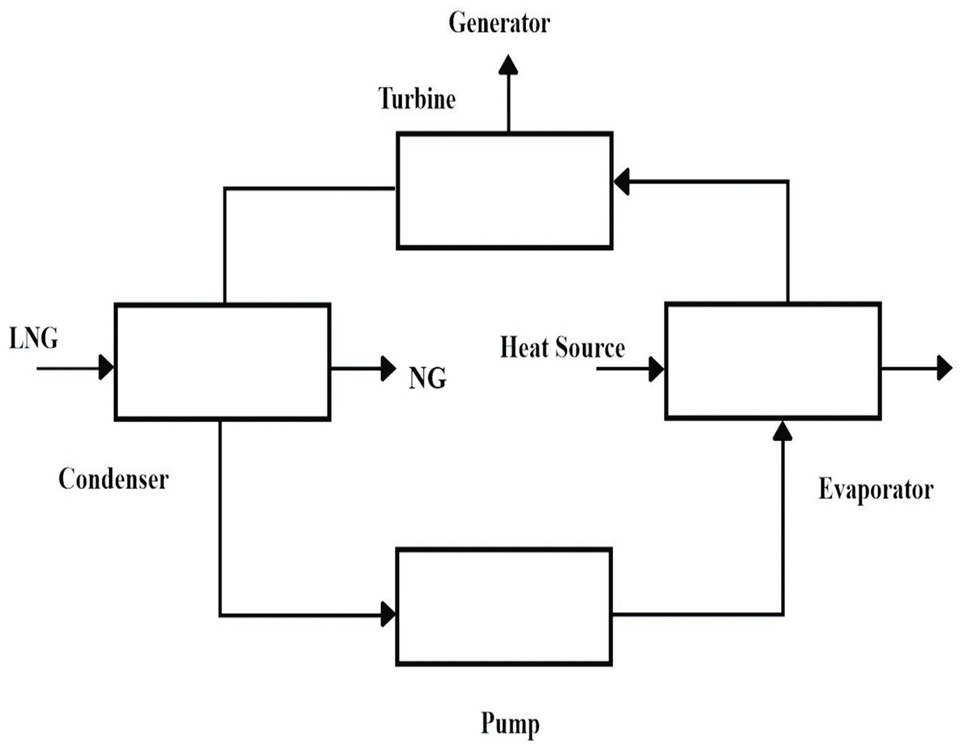
The transformation of low grade heat energy into electric power is the major property of Organic Rankine cycle (ORC) [10]. The investigation of this power cycle efficiencies and the turbine has paramount importance for identification of their electricity production performance. It is also crucial to select environmentally affable organic working fluids those have compatibility with ORC facility [11]. Japan was the first country to utilize and recover LNG cold energy with ORC at Senboku terminal in 1979. There were used Propane (C3H8) as working fluid and hot sea water as thermal resource in evaporator. There was total electric energy generation was 1.45 MW [12]. ORC has emerged as suitable option to exploit LNG cold energy to produce electricity [13]. The LNG cold energy has capability to improve the power cycle efficiency and minimize greenhouse gases emissions [14]. Computational studies show that the Genetic algorithm (GA) has ability to increase the electricity production from ORC [15].
The world economy is considerably dependent on fossil fuels at present. These energy sources produce huge quantities of environmental contaminants. Considering these serious environmental challenges, it has become necessary to utilize clean energy fuels to control contaminant emissions [16]. Natural gas (NG) is a clean fuel because of its chemical composition, and it is quickly becoming a primary power source with the benefit of clean and effective combustion and multiple usages in vehicles, energy generation plants, industrial purposes, and as a kitchen gas [17]. The worldwide NG demand increased up to 3.67 trillion cubic meters (TCM) in 2017. Their consumption is expected to grow around 4.9 TCM till 2040 [18]. Liquefied natural gas (LNG) has cold energy around (830 to 860 kJ/kg) [19]. Therefore, efforts must be made to develop technologies for utilizing LNG’s cold energy potential. This cold energy has the potential to run the cryogenic processes. Furthermore, this source can produce clean energy and curtails environmental pollutants such as CO2.
A substantial quantity of energy is consumed in LNG production from NG. Regasification is the process by which LNG is changed back into its gaseous phase [20]. The LNG regasification has strong potential for energy regeneration [21]. The majority of LNG regasification terminals are functioning without any energy regeneration technique. This recovered energy can be used to increase power generation efficiency [22] and to run cryogenic processes [23]. The world’s scientists are well aware of this beneficial proposal. They are working to develop different integrated energy systems integrated with LNG regasification facilities.
Cryogenic CO2 capture has not been extensively investigated like amine absorption or oxy-combustion. It is because of the reason that it is analyzed as an energy-intensive technique, although it produces liquid CO2 [24]. The prominent cryogenic technologies that can be employed to capture CO2 are cryogenic distillation, external cooling loop cryogenic carbon capture (CCCECL), anti-sublimation (ANSU) CO2 capture, the CryoCell cryogenic process, and the Stirling cooler system (SCS) [25]. These options are not considered as energy-efficient or cost-effective processes.
Moreover, the carbon capture and storage (CCS) technique is quite promising and one of the quickest solutions to confront environmental change [26]. Many programs are underway globally for developing an effective and minimal energy consumption CCS technique [27]. The specific techniques that are employed for capturing CO2 are solvent absorption, membrane separation, adsorption, and low temperature separation [28]. The main cryogenic or low-temperature separation methods are liquefaction and ANSU separation. These methods can be employed by recycling dissipated cold energy. According to the CO2 phase diagram, it is evident that liquefaction needs high pressure, up to 15,000 kPa. In the ANSU technique, CO2 is converted directly from a gaseous state at a pressure lower than its triple point (for ANSU pressure at −78 °C, this is 100 kPa). Because of such impactful benefits, including lower pressure systems for plant safety and relatively minimal energy consumption, cryogenic ANSU CO2 capture has an edge over other techniques [29].
Cryogenics is a new approach in comparison to different biogas purification technologies. It comprises the purification of gases relative to their condensation or sublimation temperatures. The selection of CO2 separating techniques among ANSU or distillation depends on the desired phase (solid or liquid) [30]. Cryogenic distillation needs high pressure and cryogenic temperatures [31]. It consumes a high amount of energy in the steps of compression and chilling. It also needs a multi-stage compression system, which negatively affects cost optimization [32]. The main components of biogas are methane (CH4) and CO2. To acquire a good purity of CH4 as a substitute for NG, CO2 and other impurities (N2, H2S, and O2) are required to be separated from biogas [33]. In the ANSU CO2 capture process [34], CO2 is separated from biogas via solidification at the heat exchanger surface (a categorically fabricated cold box) and removed subsequently through the surface in a liquid or vapor state with better product quality [34]. Biomethane can be liquified (also called LBM) at a substantially lower price through the ANSU process in comparison to the cryogenic distillation process [32].
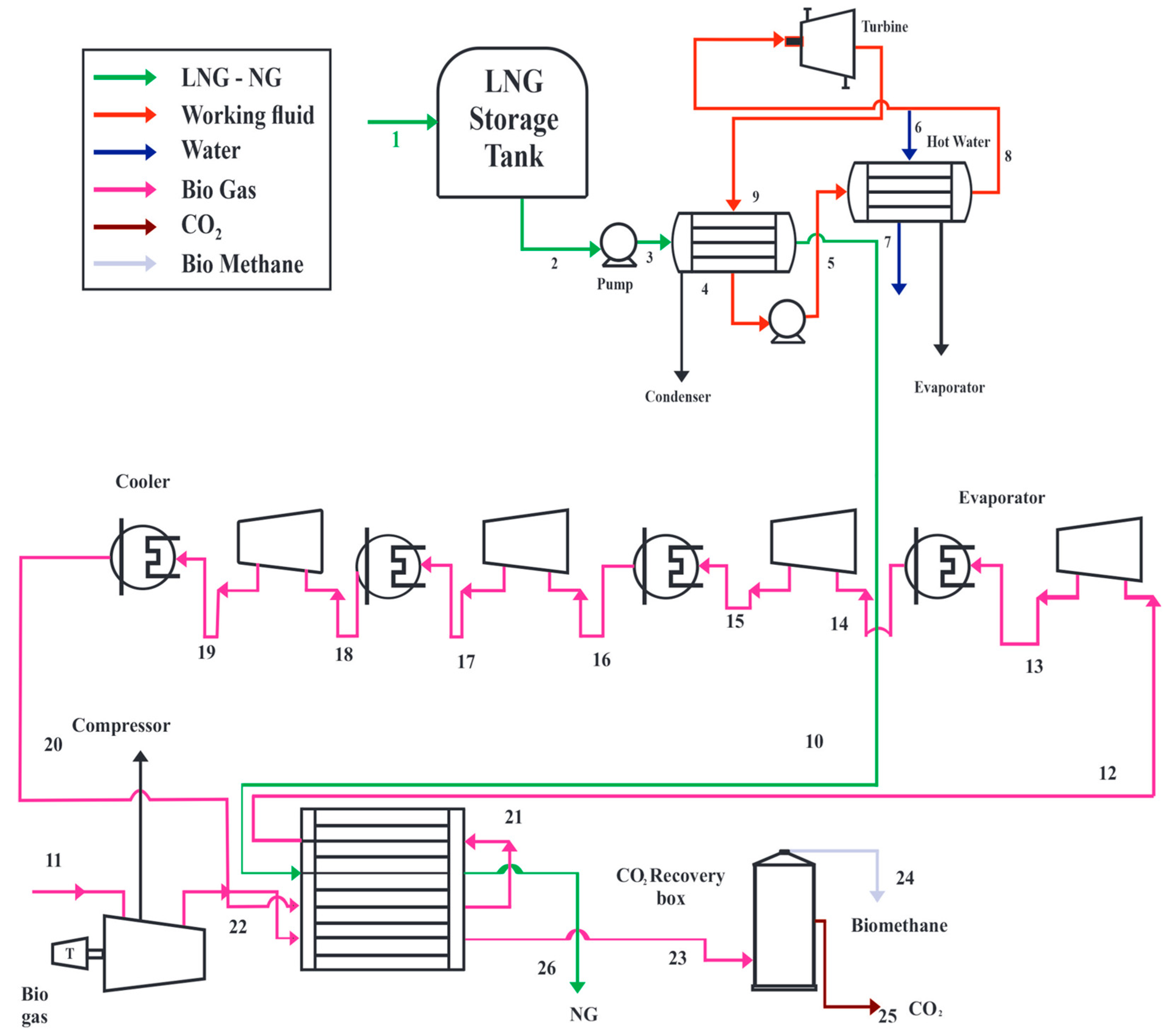
In this research study, a novel integrated energy system of LNG regasification—ORC— and an anti-sublimation process uniting a biogas system is proposed. This system produces electrical energy from LNG integration at ORC. The ANSU CO2 low-temperature capture is highly energy consuming and costly process. According to studies, it is now established that using LNG cold energy for the ANSU process appreciably improves the thermodynamic and technoeconomic feasibility of the process, i.e.,; (energy and exergy efficiencies). The environmental regulation bodies, government authorities, energy development boards, industrialists, and other related fields may benefit from this poly-generation (tertiary) system. In the coming years, focusing on economic optimization of the process (product cost) is the key to materializing this proposed energy system on a commercial basis.
This paper is compiled in such a manner that initially the benefits and importance of clean energy recovery and the sustainability of cold energy recovery techniques are discussed in (Section 1 and Section 2). Section 3 delineates the methodology to optimize this system. It also devised a model to utilize clean energy sources such as ORC. In Section 4, the obtained results of thermodynamic and techno-economic assessments are elaborated. And finally, conclusions along with future directions are delineated in Section 5.

2. Literature Review

Regasification terminals are now the center of attention for exploiting the potential of LNG’s cold energy. In regasification the of LNG, the temperature gradient is from −161 °C to ambient temperature. This cold energy has an estimated worldwide potential of producing 100 billion kWh and its market value is around 10 billion USD and increasing. Japan is taking measures to exploit this cold energy potential by producing electric power [12]. LNG cold energy can be efficaciously utilized in an ORC condenser, which is a clean geothermal source [35]. In this power production cycle, careful manipulation of organic working fluids/refrigerants is required to generate power [36]. Studies have shown that ORC is an efficient power generation technology. It is due to the fact that the maximum energy efficiency of an ORC configuration is around 67%. While, the Stirling, Brayton, and Kalina power cycles energy efficiencies are 37.2%, 51.2%, and 13.45%, respectively [37]. GA has the key potential for optimizing the ORC for better results [38]. Hereafter, clean electricity can be obtained using this geothermal source [39]. In addition, LNG cold energy can run industrial cryogenic processes [40], similar to ANSU.
For many decades, various investigations have been performed to discuss the CCS techniques from the perspective of elaborating their process parameters. As a result, environmental problems are on the rise due to growing energy demands and the burning of fossil fuels [41]. In this context, Yurata et al. purified the hydrogen (H2) by separating CO2 using the ANSU process in 2019. The total energy consumption for the removal of one kg CO2 was 8.19–11 (MJ/kg) [42]. In 2020, Gatti et al. mentioned the technical and economic capability of CO2 capture processes. The result shows that the ANSU process can separate CO2 from flue gas of natural gas fired plant, and its total equipment cost is 159 million [43]. In 2021, Cann et al. conducted an experimental study using the CO2 anti-sublimation mechanism in CCS. There was a comparison made between ceramic and steel bed materials to enhance CO2 removal [44]. In 2022, Ababneh et al. investigation also purified flue gas, limiting 0.3% CO2 in clean gas, using a combination of anti-sublimation and a solid–vapor separation unit [45]. In 2022, Naquash et al. worked on CO2 removal from liquefied hydrogen using ANSU. This system has a total acquisition cost, energy consumption, and exergy efficiency of up to 52.8 million$/y, 9.62 kWh/kg, and 31.5%, respectively [46].
In the present energy scenario of the world, it is high time to propose an effective and economically viable multi-dimensional energy system that purifies raw gases and provides a clean energy recovery system. Considering the abovementioned literature, some significant configurations are proposed to make clean electrical energy.

Contributions of This Paper

This simulation research work is making these contributions to the current scientific literature:
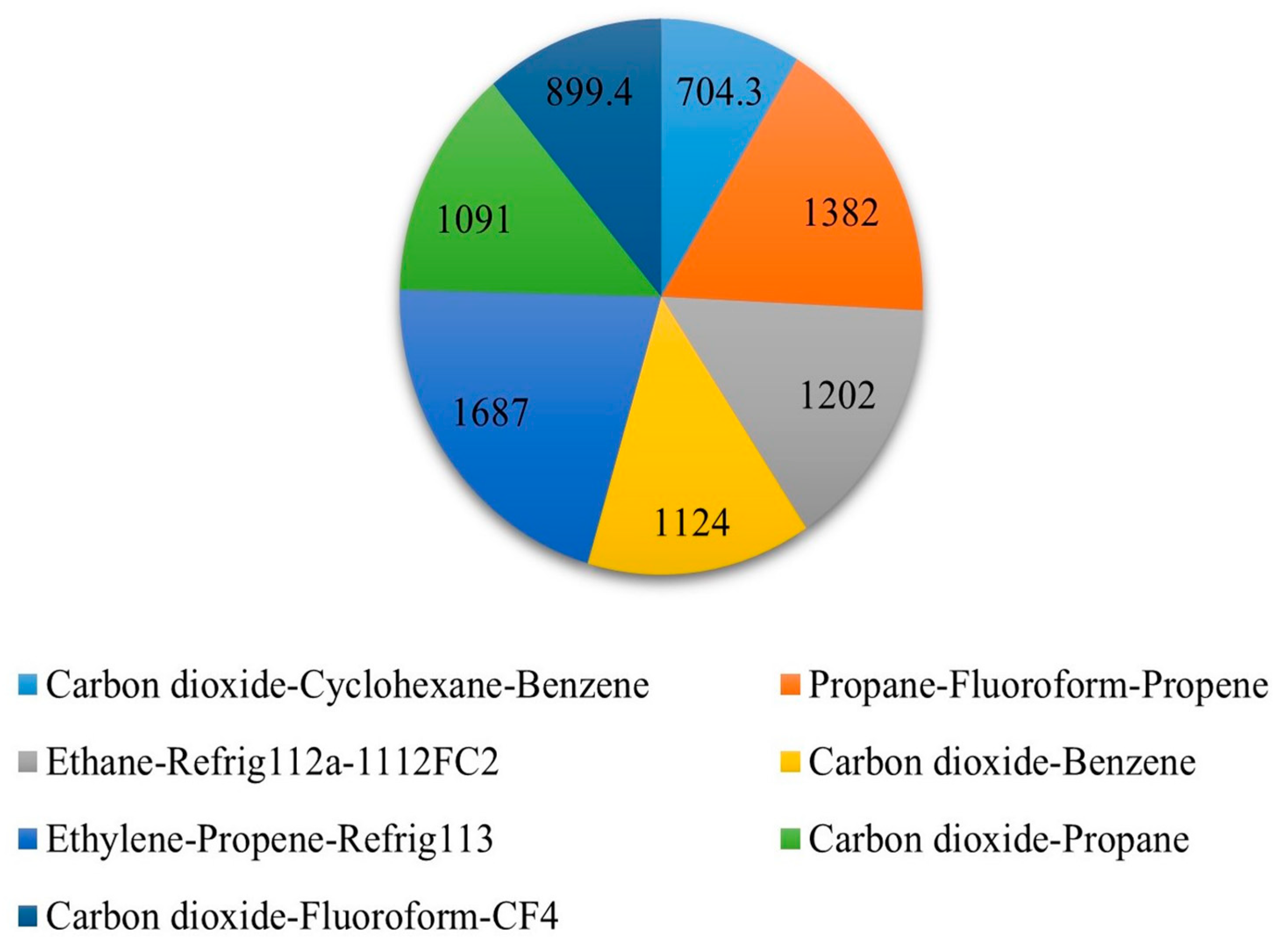
  • The present research work shows unique thermodynamic and economic comparisons among 14 configurations of LNG regasification and electricity production with a capacity of around 200 million tons per year. This study’s goal is to increase system efficiency and CO2 separation through the utilization of LNG cryogenic cold energy. The analyzed solutions could assist the national electric grid as an additional power source, meet power requirements in carrier ships at ports, provide electricity to port industries areas, provide electric power to railways, supply power to naval strategic bases at ports, and provide electric supply to medical and education centers of developing areas in the vicinity. It also supports the policy of minimal environmental impact, supports cold-ironing, and the decrease of the environmental impact of maritime transports. This low-cost ANSU purification system can be useful for the world’s largest biogas plant in Vaasa, central Finland.
  • In the current scientific literature, modes of power output and its economic analysis are discussed. The present work demonstrated both first and second law efficiency and techno-economic values.
  • The avent-grade regasification system parameters are described, and a smart differentiation is presented on the basis of working fluid selection for proposed energy system configurations.

3. Conceptual Framework

The objective of the present investigation is to propose and recognize productive configurations to formulate clean energy via LNG regasification and also to purify the biogas. It can relieve the environmental, energy, and economic burdens and will have a positive contribution to the current energy scenario of any power deficient country. At first, there are reported configurations which can make valuable electric power and remove CO2 using LNG’s cold energy. Afterwards, a description of the adopted methodology is presented. These proposed configurations are distinguished by thermodynamic and technoeconomic assessments.

3.1. Hypothesis

In this work, a novel integrated LNG regasification-ORC-ANSU energy system is demonstrated in Figure 1. It consists of installations to produce electric power and separate CO2 from biogas. In this cryogenic process activity, this energy system has the following properties:
  • Hot sea water is used as a thermal resource at the ORC evaporator.
  • Working fluid manipulation in combined and single mode to increase net turbine power.
  • The LNG pump pressure is higher than the present studies, which is 35,000 kPa.

3.2. Methodology

The major assumptions and explanations of the mathematical models devised to make the present energy system are described in Table 1. The LNG integrated ORC energy system is described in Figure 2. Additionally, the particulars of the optimization procedure and the adopted optimization technique (algorithm) are discussed ahead.

3.2.1. Model of the System

The thermodynamic modeling of all the configurations were performed in Aspen-Hysis V11 [47]. The fixed parameters of the numerical simulation are reported in Table 1.
Uniform (steady state) function;
Constant values of adiabatic and polytropic efficiencies at mechanical devices;
Constant pressure gradient at heat devices;
Total adiabatic thermal devices;
LNG constituent: pure CH4;
Biogas fraction: CH4: 0.65 and CO2: 0.35.

3.2.2. Optimization Algorithm

In this work, the GA is used for turbine optimization in this energy network [48]. This optimization can be upgraded by recognizing the categorization process through an applied algorithm [49]. Current market trends suggest reducing the operating costs of the process [50]. Therefore, performance monitoring has a vital role where variables require adjustment [51]. The industrial progress from electronic stages in these systems is outdated in comparison to the mechanical components, which produces complications in their different applications [52]. Therefore, machinery performance assessment is an engineering problem that needs to be studied intensively [53].
The GA has the property to acquire natural selection and genetic theory by uniting a survival rule of most-suitable relative to biological evolution through random details transfer [54]. To efficiently secure the optimum value of the objective function, GA executes these steps: firstly, GA employs an initial population in which individuals are irregularly produced. After that, the objective function (turbine power) is calculated. A segment of the population is chosen, and the methods of crossover, reproduction, and mutation are constantly applied until the optimized population has converged. Figure 3 demonstrates the process optimization using the GA optimizer. Table 2 reports the operating parameters of GA used in the present system optimization.
The GA is coded in the MATLAB R2021a environment. MATLAB R2021a is interfaced with or coupled with Aspen Hysys V11 to complete the optimization step. The total number of iterations was 400 for all 14 poly-generation (tertiary) configurations.

3.3. System Modeling and Analysis

The parameters and variables which are employed for this poly-generation system analysis are described there.

3.3.1. Thermodynamic Analysis

Energy efficiency of the novel integrated LNG regasification-ORC-ANSU energy system to be estimated from the first law of thermodynamics mentioned in [55].
Energy   Efficiency   % = W o u t Q i n   Q i n × 100
Whereas work output = Wout and energy input = Qin.
Exergy analysis describes how much input exergy is taken by the system [56]. Exergy destruction demonstrates the inadequacy of the system analytically. The main objective of the exergy analysis is to choose the location and amount of irreversible entropy production in various components of a process as well as the parameters affecting its generation. Besides the assessment of the efficiency of various parts of a system, feasible solutions for improving the system efficiency are also determined in exergy analysis [57]. In particular, exergy is characterized as the maximum content of work that can be performed by the system when it reaches a standard or dead state. Dead state is indicated as 25 °C and 101.325 kPa [58]. Exergy efficiency was counted using the second law of thermodynamics as reported in [59].
Exergy   Efficiency   % = E e l , n e t W l n g × S e , l n g W N G × S e , n g × 100 .
Whereas
Eel,net = Total energy by turbines and recovery system
Wlng = Mass of LNG entering into system
Se,lng = Total exergy of LNG
Se,ng = Total exergy of regasified natural gas

3.3.2. Economic Analysis

In the ORC energy system, the heat exchanger’s economic value (price) is equivalent to 80–90% of the entire system price. This is due to the fact that this heat transfer equipment covers a major part of the ORC system, their correct work measurement displays a paramount part in upgrading the total value of this ORC based energy system. In the present investigation, the ORC system consists of a turbine, pump, and heat transfer equipment (condenser and evaporator). The cost assessment is established on the total investment cost, which comprises the equipment price of every item in the system. The bare module price, CBM for an individual item is the product of the item price Cp and the module price element Fbm [60].
For heat transfer equipment,
C BM = C P + F bm = C P × B 1 + B 2 × F m × F P
log C P =   K 1 +   K 2 logA +   K 3 logA 2
log F P =   C 1 +   C 2 logP +   C 3 logA 2
B1 and B2 represent the constants established with respect to the heat exchanger category, Fm shows the material factor, and FP represents the pressure factor. The A and P denote the area and pressure of the item simultaneously. These economics analysis parameter values are delineated in Table 3.
For turbine,
C B M = C P + F b m = C P × B 1 + B 2 × F m × F P
log C P = K 1 +   K 2 log W e x p +   K 3 log W e x p 2
Whereas Wexp shows the electric power obtained from turbine.
For the pump,
C B M = C P + F b m = C P × B 1 + B 2 × F m × F P
log C P = K 1 +   K 2 logW p u m p +   K 3 logW p u m p 2
Whereas Wpump power needed to derive the pump.
For the compressor,
C B M = C P + F b m = C P × B 1 + B 2 × F m × F P
log C P = K 1 +   K 2 logW c o m p + K 3 logW c o m p 2
log F P = C 1 +   C 2 logP + C 3 logP 2
Whereas Wcomp power needed to derive the compressor.
The total investment value of this system can be counted from Equation (13).
C tot = C BM , hx + C BM , exp + C B M , c o m p + C BM , pump 2001 × CEPCI 2018 CEPCI 2001  
CEPCI shows the chemical engineering plant cost index. The real investment prices for 2018 can be counted from the price value for 2001 shown by CEPCI. The CEPCIs values for 2001 and 2018 are 397 and 648.7, simultaneously as reported in [61].

3.3.3. Techno-Economic Assessment

The techno-economic value of this reported energy system is demonstrated by the net present value (NPV) in Equation (14).
NPV = C tot + t = 1 n TF 1 + i t
Whereas Ctot shows the total capital investment, TF the total cash flow in year n, i the interest rate set as 5%, and n the lifetime = 20 years.

3.4. Results Validation

In this section, results validation is carried out by analyzing the obtained results with past investigations of each model to confirm that the simulation results are correct. Upon novel integration with this energy network, their model results validation is executed by considering each sub system. The results in Ref. [59] were taken into consideration to validate the ORC and LNG-NG loops. The optimizing parameters are LNG pump inlet pressure and working fluids inlet (pressure, flow rate, and temperature) at the turbine. The ORC validation is performed by regulating working fluids.
The comparison results are in fine consensus, and relative errors are in allowed domain. The small discrepancies come out due to the fact that Ref. [59] employed Refprop’s equation of state (EoS) as a fluid property package and particle swarm optimization (PSO). On the other side, there are exploited Peng Robinson fluid property package and GA in the current study. While the preceding studies of LNG regasification-ORC energy systems did not show the robust manipulation of organic working fluids and LNG pump inlet pressure to generate efficient clean energy. For the ANSU process validation, the results in Ref. [32] were considered.

4. Results and Discussion

In this section, the simulation results of power generation, energy efficiency, exergy efficiency, and NPV are presented.

4.1. Power Generation

In Figure 4, the obtained power is (MW) up to 2492, 1741, 1670, 1192, 1042, 940.7, and 837.7 by regulating seven working fluids in single mode at this energy system. Figure 5 shows the obtained power output (MW) up to 1687, 1382, 1202, 1124, 1091, 899.4, and 704.3 for manipulating seven working fluids in multiple modes. From this study, cyclohexane emerges as the most suitable working fluid to generate clean electric energy around 2492 MW, which slightly surpasses pentane, which secures power around 1741 MW. Table 4, Table 5 and Table 6 report the operating values of configurations I, II, and III deploying cyclohexane carbon dioxide and butane as the working fluids in the ORC energy system. The electric production by turbine was maximized after each iteration using GA. The selection process consists of initialization, fitness evaluation, subset of solution, reproduction, replacement, and termination. The obtained results demonstrate that the clean electric energy generated from turbines is based on the working fluid thermodynamic properties [62].

4.2. Energy Efficiency

The obtained energy efficiencies of the novel integrated energy system are demonstrated in Figure 6 and Figure 7. Using cyclohexane, butane, pentane, ethylene, propane, ethane, and CO2 in a single mode of the ORC, the obtained energy efficiencies (%) are around 57.13, 50.34, 11.59, 9.10, 40.24, 20.09, 11.59 and 26.52 respectively. On the other side, the obtained energy efficiencies (%) of working fluids CO2-fluoroform-CF4 (WFn-I), CO2-propane (WFn-II), ethylene-propene-ref-113 (WFn-III), CO2-benzene (WFn-IV), ethane-ref112a-112FC2 (WFn-V), propane-fluoroform-propene (WFn-VI) and CO2-cyclohexane-benzene (WFn-VII) in multiple modes are found as 30.01, 25.55, 11, 7.33, 2.56, 1.54, and 0.59 simultaneously.

4.3. Exergy Efficiency

The obtained exergy efficiencies of this energy network are mentioned in Figure 8 and Figure 9. The obtained exergy efficiencies (%) are up to 76.20, 74.30, 64, 34.67, 37, 63.89, and 40.10 by manipulating the working fluids cyclohexane, butane, pentane, ethylene, ethane, propane, and CO2 in a single mode of the ORC. The multiple modes of working fluids or refrigerants CO2-fluoroform-CF4 (WFn-I), CO2-propane (WFn-II), ethylene-ref112a-refrig-113 (WFn-III), CO2-benzene (WFn-IV), ethane-ref112a-112FC2 (WFn-V), propane-fluoroform-propene (WFn-VI) and CO2-cyclohexane-benzene (WFn-VII) manipulation of the ORC can produce exergy efficiencies (%) around 36.51, 44.21, 64.53, 39.50, 37.67, 55.69, and 31.34 simultaneously.

4.4. Economic Assessments

The calculated total equipment cost of this proposed energy network is around 16.4 million USD. The NPV of cyclohexane configuration I is 19.5. It is obtained by calculating the total equipment cost and cash flow values up to 16.4 million USD, and 4.34 × 10³ million USD, respectively. Figure 10 and Figure 11 show the NPV values of 14 configurations having different cash flows. Table 7 reports the comparison between results of the present study and similar work.

5. Conclusions and Future Directions

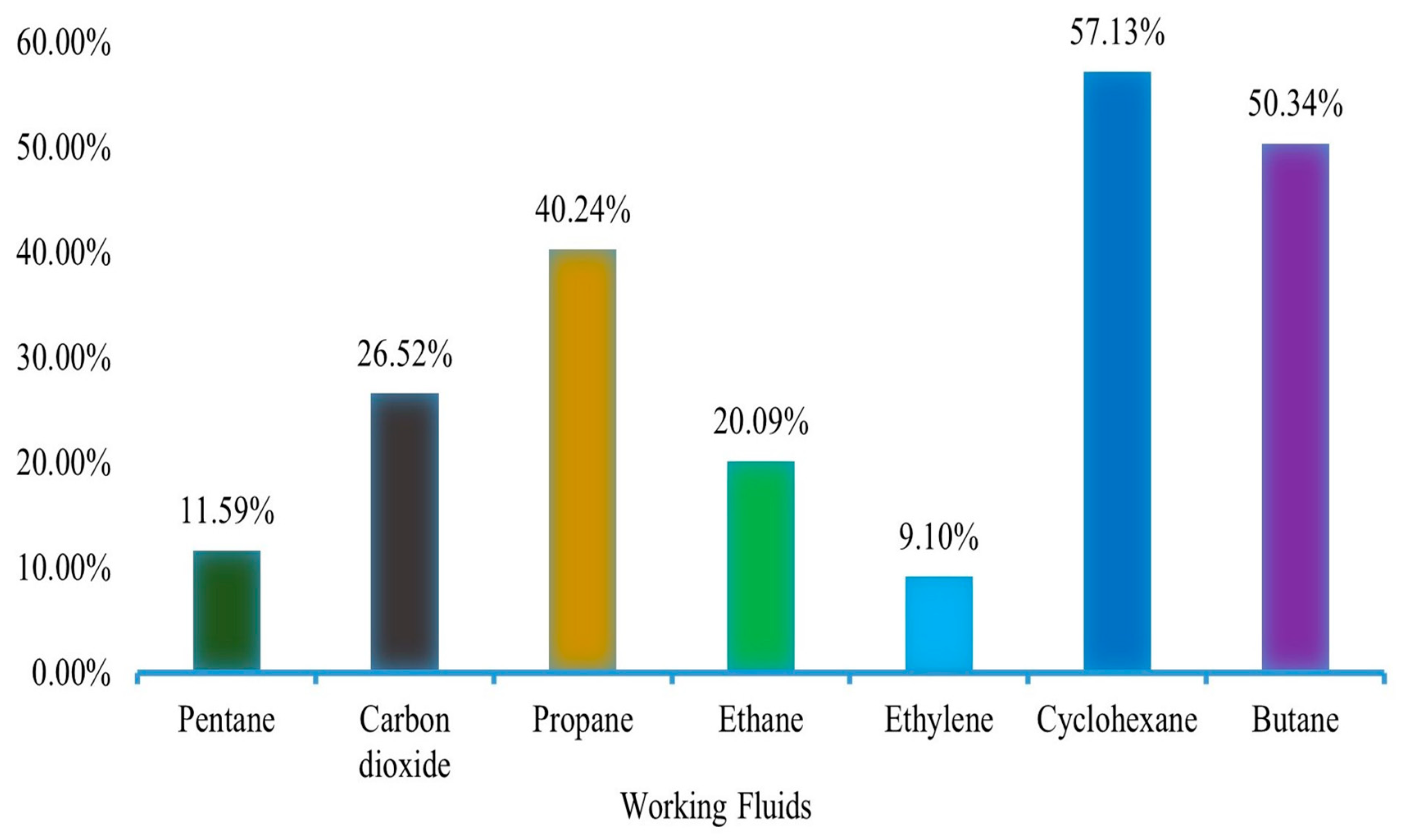
It is proven from this investigation that this novel integrated energy system has energy efficiency up to 57.13 %. It is due to the careful manipulation of organic working fluids in the ORC turbine. It is confirmed that the ORC energy system is identical to a steam engine. Now, it has materialized as a real clean energy generation system with technological advancement. Its major features are good flexibility and conversion efficiency at cryogenic conditions. There is a need to enhance its economic viability through the latest integration techniques, various manufacturing processes and materials, more novel development in optimization techniques, and low-cost, environmentally affable working fluids in the near future.
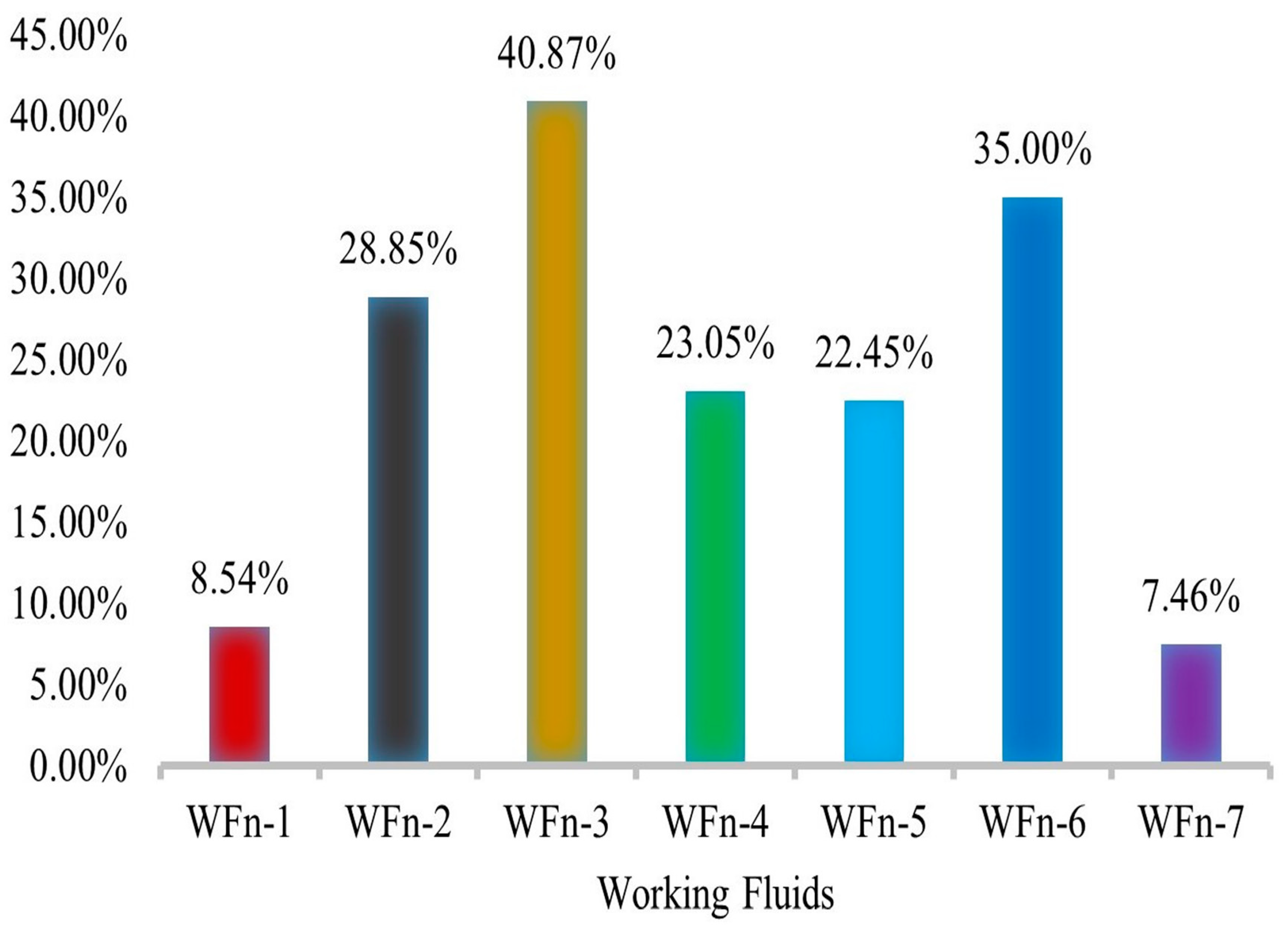
It is verified that the manipulation of a single working fluid of the ORC can generate a large amount of power, up to 2492 MW, in comparison to working fluids of multiple modes. It is because of this reason that its thermodynamic characteristics i.e., (i)—Critical temperature, (ii)—Boiling temperature, (iii)—Specific heat, (iv)—Latent heat of evaporation, (v)—Heat transfer coefficient, (vi)—Enthalpy drop, (vii)—Thermal stability, (viii)—Viscosity, (ix)—Specific volume, do not coincide with each other. It is also evident from the obtained results that the 2nd law of thermodynamics efficiency is higher than the 1st law of thermodynamic efficiency for identical energy systems.
This research work discloses a business case that is not shown in previous scientific studies showing consumption of LNG cold energy to generate clean electric energy and running ANSU CO2 capture process. It devises LNG regasification capacity 200 million tons annually at a seaport vicinity. It positively portrays to generate clean electric energy and minimizing an environmental contaminant (CO2) from novel integrated bio-gas setup via LNG cold energy.
The heat transfer devices that are linked to the presented novel integrated energy system are classified as condenser/regenerator, evaporator, and preheater. It is now evident that shell and tube heat exchangers show better results. For practical implications, there is also a recommendation to deploy shell and tube heat exchanger as condenser and evaporator in a practical ORC facility. It is due to its features of optimum heat transfer, minimum LNG freezing risk, on-shore/off-shore operation modes, and maintenance. This investigation makes a call to consume seaport area hot water in the ORC evaporator with the effects of its facile handling and no cost in summer.
The biogas has a large CO2 content of around 35%, and there is a large energy requirement for its cryogenic capture. It can be resolved by this proposed novel integrated clean energy system utilizing LNG cold energy. In this situation, environmental regulatory bodies, government authorities, industrialists, and academics can take advantage of the obtained thermodynamic and techno-economic assessments of this innovative integrated energy network.

Author Contributions

S.U.K.S.: Methodology, Investigation, Softwares, Writing—original draft, M.K.M.: Supervision and funding acquisition. M.S.A.: Methodology, Proof reading. All authors have read and agreed to the published version of the manuscript.

Funding

This work was supported by the Higher Education Commission of Pakistan grant no. 119-FEG2-012 funded by the Pakistan government.

Data Availability Statement

This manuscript includes the modeling/simulation datasets.

Conflicts of Interest

The authors declare that there is no conflict of interest.

References

  1. Alsagr, N.; van Hemmen, S. The impact of financial development and geopolitical risk on renewable energy consumption: Evidence from emerging markets. Environ. Sci. Pollut. Res. 2021, 28, 25906–25919. [Google Scholar] [CrossRef] [PubMed]
  2. Santika, W.G.; Anisuzzaman, M.; Bahri, P.A.; Shafiullah, G.M.; Rupf, G.V.; Urmee, T. From goals to joules: A quantitative approach of interlinkages between energy and the Sustainable Development Goals. Energy Res. Soc. Sci. 2019, 50, 201–214. [Google Scholar] [CrossRef]
  3. Kober, T.; Schiffer, H.-W.; Densing, M.; Panos, E. Global energy perspectives to 2060–WEC’s World Energy Scenarios 2019. Energy Strateg. Rev. 2020, 31, 100523. [Google Scholar] [CrossRef]
  4. Stern, D.I. Energy and economic growth. In Routledge Handbook of Energy Economics; Routledge: London, UK, 2019; pp. 28–46. ISBN 1315459655. [Google Scholar]
  5. Han, G.; Lee, S.; Lee, J.; Lee, K.; Bae, J. Deep-learning- and reinforcement-learning-based profitable strategy of a grid-level energy storage system for the smart grid. J. Energy Storage 2021, 41, 102868. [Google Scholar] [CrossRef]
  6. Karmaker, A.K.; Rahman, M.M.; Hossain, M.A.; Ahmed, M.R. Exploration and corrective measures of greenhouse gas emission from fossil fuel power stations for Bangladesh. J. Clean. Prod. 2020, 244, 118645. [Google Scholar] [CrossRef]
  7. Minx, J.C.; Lamb, W.F.; Andrew, R.M.; Canadell, J.G.; Crippa, M.; Döbbeling, N.; Forster, P.M.; Guizzardi, D.; Olivier, J.; Peters, G.P. A comprehensive and synthetic dataset for global, regional, and national greenhouse gas emissions by sector 1970–2018 with an extension to 2019. Earth Syst. Sci. Data 2021, 13, 5213–5252. [Google Scholar] [CrossRef]
  8. Marks, M.; Klikocka, H. Assumptions and Implementation of Climate and Energy Policy under the Europe 2020 Strategy. Eur. Res. Stud. J. 2020, 23, 1041–1059. [Google Scholar] [CrossRef]
  9. Aalbu, K.; Longva, T. From Progress to Delay: The Quest for Data in the Negotiations on Greenhouse Gases in the International Maritime Organization. Glob. Environ. Polit. 2022, 22, 136–155. [Google Scholar] [CrossRef]
  10. Martínez-Sánchez, R.A.; Rodriguez-Resendiz, J.; Álvarez-Alvarado, J.M.; Macías-Socarrás, I. Solar Energy-Based Future Perspective for Organic Rankine Cycle Applications. Micromachines 2022, 13, 944. [Google Scholar] [CrossRef]
  11. Álvarez-Alvarado, J.M.; Ríos-Moreno, G.J.; Ventura-Ramos, E.; Ronquillo-Lomelí, G.; Trejo-Perea, M. Experimental study of a 1-kW organic rankine cycle using R245fa working fluid and a scroll expander: A case study. IEEE Access 2019, 7, 154515–154523. [Google Scholar] [CrossRef]
  12. Çengel, Y.A. Power generation potential of liquified natural gas regasification terminals. Int. J. Energy Res. 2020, 44, 3241–3252. [Google Scholar] [CrossRef]
  13. Gao, W.; Wu, Z.; Tian, Z.; Zhang, Y. Experimental investigation on an R290-based organic Rankine cycle utilizing cold energy of liquid nitrogen. Appl. Therm. Eng. 2022, 202, 117757. [Google Scholar] [CrossRef]
  14. He, T.; Chong, Z.R.; Zheng, J.; Ju, Y.; Linga, P. LNG cold energy utilization: Prospects and challenges. Energy 2019, 170, 557–568. [Google Scholar] [CrossRef]
  15. Sarmiento, A.L.E.; Camacho, R.G.R.; de Oliveira, W.; Velásquez, E.I.G.; Murthi, M.; Gautier, N.J.D. Design and off-design performance improvement of a radial-inflow turbine for ORC applications using metamodels and genetic algorithm optimization. Appl. Therm. Eng. 2021, 183, 116197. [Google Scholar] [CrossRef]
  16. Mutezo, G.; Mulopo, J. A review of Africa’s transition from fossil fuels to renewable energy using circular economy principles. Renew. Sustain. Energy Rev. 2021, 137, 110609. [Google Scholar] [CrossRef]
  17. Alhajeri, N.S.; Dannoun, M.; Alrashed, A.; Aly, A.Z. Environmental and economic impacts of increased utilization of natural gas in the electric power generation sector: Evaluating the benefits and trade-offs of fuel switching. J. Nat. Gas Sci. Eng. 2019, 71, 102969. [Google Scholar] [CrossRef]
  18. Ye, Z. Study on the natural gas consumption and its change prediction. In Journal of Physics: Conference Series; IOP Publishing: Bristol, UK, 2020; Volume 1549, p. 42103. [Google Scholar]
  19. Yu, P.; Liu, H.; Zhou, S.; Che, D. Thermodynamic analysis of a cryogenic power generation system recovering both sensible heat and latent heat of flue gas. Energy Convers. Manag. 2021, 227, 113615. [Google Scholar] [CrossRef]
  20. Huerta, F.; Vesovic, V. A realistic vapour phase heat transfer model for the weathering of LNG stored in large tanks. Energy 2019, 174, 280–291. [Google Scholar] [CrossRef]
  21. Park, J.; You, F.; Cho, H.; Lee, I.; Moon, I. Novel massive thermal energy storage system for liquefied natural gas cold energy recovery. Energy 2020, 195, 117022. [Google Scholar] [CrossRef]
  22. Pospíšil, J.; Charvát, P.; Arsenyeva, O.; Klimeš, L.; Špiláček, M.; Klemeš, J. Energy demand of liquefaction and regasification of natural gas and the potential of LNG for operative thermal energy storage. Renew. Sustain. Energy Rev. 2019, 99, 1–15. [Google Scholar] [CrossRef]
  23. Wu, Y.; Xiang, Y.; Cai, L.; Liu, H.; Liang, Y. Optimization of a novel cryogenic air separation process based on cold energy recovery of LNG with exergoeconomic analysis. J. Clean. Prod. 2020, 275, 123027. [Google Scholar] [CrossRef]
  24. Tan, W.-L.; Ahmad, A.L.; Leo, C.P.; Lam, S.S. A critical review to bridge the gaps between carbon capture, storage and use of CaCO3. J. CO2 Util. 2020, 42, 101333. [Google Scholar] [CrossRef]
  25. Song, C.; Liu, Q.; Deng, S.; Li, H.; Kitamura, Y. Cryogenic-based CO2 capture technologies: State-of-the-art developments and current challenges. Renew. Sustain. Energy Rev. 2019, 101, 265–278. [Google Scholar] [CrossRef]
  26. Yoro, K.O.; Daramola, M.O. Chapter 1—CO2 emission sources, greenhouse gases, and the global warming effect. In Advances in Carbon Capture; Rahimpour, M.R., Farsi, M., Makarem, M.A., Eds.; Woodhead Publishing: Sawston, UK, 2020; pp. 3–28. ISBN 978-0-12-819657-1. [Google Scholar]
  27. Romasheva, N.; Ilinova, A. CCS projects: How regulatory framework influences their deployment. Resources 2019, 8, 181. [Google Scholar] [CrossRef] [Green Version]
  28. Nakao, S.; Yogo, K.; Goto, K.; Kai, T.; Yamada, H. Advanced CO2 Capture Technologies: Absorption, Adsorption, and Membrane Separation Methods; Springer: Berlin/Heidelberg, Germany, 2019; ISBN 3030188582. [Google Scholar]
  29. Kanjilal, B.; Nabavinia, M.; Masoumi, A.; Savelski, M.; Noshadi, I. Challenges on CO2 capture, utilization, and conversion. In Advances in Carbon Capture; Elsevier: Amsterdam, The Netherlands, 2020; pp. 29–48. [Google Scholar]
  30. Baena-Moreno, F.M.; Rodríguez-Galán, M.; Vega, F.; Malico, I.; Navarrete, B. Potential Processes for Simultaneous Biogas Upgrading and Carbon Dioxide Utilization. In Engineering Solutions for CO2 Conversion; Wiley: Hoboken, NJ, USA, 2021; pp. 125–144. [Google Scholar]
  31. Yousef, A.M.; El-Maghlany, W.M.; Eldrainy, Y.A.; Attia, A. Upgrading biogas to biomethane and liquid CO2: A novel cryogenic process. Fuel 2019, 251, 611–628. [Google Scholar] [CrossRef]
  32. Spitoni, M.; Pierantozzi, M.; Comodi, G.; Polonara, F.; Arteconi, A. Theoretical evaluation and optimization of a cryogenic technology for carbon dioxide separation and methane liquefaction from biogas. J. Nat. Gas Sci. Eng. 2019, 62, 132–143. [Google Scholar] [CrossRef]
  33. Baitha, R.; Kaushal, R. Numerical and experimental study of biogas, methane and carbon dioxide produced by pre-treated slurry. Int. J. Ambient Energy 2020, 41, 198–204. [Google Scholar] [CrossRef]
  34. Naquash, A.; Qyyum, M.A.; Haider, J.; Lim, H.; Lee, M. Renewable LNG production: Biogas upgrading through CO2 solidification integrated with single-loop mixed refrigerant biomethane liquefaction process. Energy Convers. Manag. 2021, 243, 114363. [Google Scholar] [CrossRef]
  35. Ng, C.; Tam, I.C.K.; Wu, D. System modelling of organic rankine cycle for waste energy recovery system in marine applications. Energy Procedia 2019, 158, 1955–1961. [Google Scholar] [CrossRef]
  36. Malwe, P.D.; Shaikh, J.; Gawali, B.S.; Panchal, H.; Dalkilic, A.S.; Rahman, S.; Alrubaie, A.J. Dynamic simulation and exergy analysis of an Organic Rankine Cycle integrated with vapor compression refrigeration system. Sustain. Energy Technol. Assess. 2022, 53, 102684. [Google Scholar] [CrossRef]
  37. Lion, S.; Vlaskos, I.; Taccani, R. A review of emissions reduction technologies for low and medium speed marine Diesel engines and their potential for waste heat recovery. Energy Convers. Manag. 2020, 207, 112553. [Google Scholar] [CrossRef]
  38. Zhang, H.; Han, Z.; Wu, D.; Li, P. Energy optimization and performance analysis of a novel integrated energy system coupled with solar thermal unit and preheated organic cycle under extended following electric load strategy. Energy 2023, 272, 127094. [Google Scholar] [CrossRef]
  39. Assareh, E.; Delpisheh, M.; Farhadi, E.; Peng, W.; Moghadasi, H. Optimization of geothermal-and solar-driven clean electricity and hydrogen production multi-generation systems to address the energy nexus. Energy Nexus 2022, 5, 100043. [Google Scholar] [CrossRef]
  40. Milani, D.; Nelson, S.; Luu, M.T.; Meybodi, M.A.; Puxty, G.; Abbas, A. Tailored solar field and solvent storage for direct solvent regeneration: A novel approach to solarise carbon capture technology. Appl. Therm. Eng. 2020, 171, 115119. [Google Scholar] [CrossRef]
  41. Shen, M.; Tong, L.; Yin, S.; Liu, C.; Wang, L.; Feng, W.; Ding, Y. Cryogenic technology progress for CO2 capture under carbon neutrality goals: A review. Sep. Purif. Technol. 2022, 299, 121734. [Google Scholar] [CrossRef]
  42. Yurata, T.; Lei, H.; Tang, L.; Lu, M.; Patel, J.; Lim, S.; Piumsomboon, P.; Chalermsinsuwan, B.; Li, C. Feasibility and sustainability analyses of carbon dioxide—Hydrogen separation via de-sublimation process in comparison with other processes. Int. J. Hydrogen Energy 2019, 44, 23120–23134. [Google Scholar] [CrossRef]
  43. Gatti, M.; Martelli, E.; Di Bona, D.; Gabba, M.; Scaccabarozzi, R.; Spinelli, M.; Viganò, F.; Consonni, S. Preliminary performance and cost evaluation of four alternative technologies for post-combustion CO2 capture in natural gas-fired power plants. Energies 2020, 13, 543. [Google Scholar] [CrossRef] [Green Version]
  44. Cann, D.; Font-Palma, C.; Willson, P. Moving packed beds for cryogenic CO2 capture: Analysis of packing material and bed precooling. Carbon Capture Sci. Technol. 2021, 1, 100017. [Google Scholar] [CrossRef]
  45. Ababneh, H.; AlNouss, A.; Al-Muhtaseb, S.A. Carbon Capture from Post-Combustion Flue Gas Using a State-Of-The-Art, Anti-Sublimation, Solid–Vapor Separation Unit. Processes 2022, 10, 2406. [Google Scholar] [CrossRef]
  46. Naquash, A.; Haider, J.; Qyyum, M.A.; Islam, M.; Min, S.; Lee, S.; Lim, H.; Lee, M. Hydrogen enrichment by CO2 anti-sublimation integrated with triple mixed refrigerant-based liquid hydrogen production process. J. Clean. Prod. 2022, 341, 130745. [Google Scholar] [CrossRef]
  47. Moradi, M.; Ghorbani, B.; Ebrahimi, A.; Ziabasharhagh, M. Process integration, energy and exergy analyses of a novel integrated system for cogeneration of liquid ammonia and power using liquefied natural gas regasification, CO2 capture unit and solar dish collectors. J. Environ. Chem. Eng. 2021, 9, 106374. [Google Scholar] [CrossRef]
  48. Cho, S.; Park, J.; Noh, W.; Lee, I.; Moon, I. Developed hydrogen liquefaction process using liquefied natural gas cold energy: Design, energy optimization, and techno-economic feasibility. Int. J. Energy Res. 2021, 45, 14745–14760. [Google Scholar] [CrossRef]
  49. Aviles, M.; Sánchez-Reyes, L.-M.; Fuentes-Aguilar, R.Q.; Toledo-Pérez, D.C.; Rodríguez-Reséndiz, J. A Novel Methodology for Classifying EMG Movements Based on SVM and Genetic Algorithms. Micromachines 2022, 13, 2108. [Google Scholar] [CrossRef] [PubMed]
  50. Hiyane-Nashiro, G.; Hernández-Hernández, M.; Rojas-García, J.; Rodriguez-Resendiz, J.; Álvarez-Alvarado, J.M. Optimization of the Reduction of Shrinkage and Warpage for Plastic Parts in the Injection Molding Process by Extended Adaptive Weighted Summation Method. Polymers 2022, 14, 5133. [Google Scholar] [CrossRef] [PubMed]
  51. Torres-Salinas, H.; Rodríguez-Reséndiz, J.; Cruz-Miguel, E.E.; Ángeles-Hurtado, L.A. Fuzzy logic and genetic-based algorithm for a servo control system. Micromachines 2022, 13, 586. [Google Scholar] [CrossRef] [PubMed]
  52. Cruz-Miguel, E.E.; García-Martínez, J.R.; Rodríguez-Reséndiz, J.; Carrillo-Serrano, R.V. A new methodology for a retrofitted self-tuned controller with open-source fpga. Sensors 2020, 20, 6155. [Google Scholar] [CrossRef]
  53. Rodríguez-Abreo, O.; Rodríguez-Reséndiz, J.; Montoya-Santiyanes, L.A.; Álvarez-Alvarado, J.M. Non-linear regression models with vibration amplitude optimization algorithms in a microturbine. Sensors 2022, 22, 130. [Google Scholar] [CrossRef]
  54. Yin, L.; Ju, Y. Process optimization and analysis of a novel hydrogen liquefaction cycle. Int. J. Refrig. 2020, 110, 219–230. [Google Scholar] [CrossRef]
  55. Ahmadi, M.H.; Alhuyi Nazari, M.; Sadeghzadeh, M.; Pourfayaz, F.; Ghazvini, M.; Ming, T.; Meyer, J.P.; Sharifpur, M. Thermodynamic and economic analysis of performance evaluation of all the thermal power plants: A review. Energy Sci. Eng. 2019, 7, 30–65. [Google Scholar] [CrossRef] [Green Version]
  56. Mousavi, S.A.; Mehrpooya, M.; Rad, M.A.V.; Jahangir, M.H. A new decision-making process by integration of exergy analysis and techno-economic optimization tool for the evaluation of hybrid renewable systems. Sustain. Energy Technol. Assess. 2021, 45, 101196. [Google Scholar] [CrossRef]
  57. Kharlampidi, D.; Tarasova, V.; Kuznetsov, M. Analysis of the effect of thermohydraulic irreversibility of processes in the cycle of a refrigeration machine with a non-azeotropic mixture of refrigerants. Technol. Audit Prod. Reserv. 2019, 3, 4–13. [Google Scholar] [CrossRef]
  58. Blanco-Marigorta, A.M.; Marcos, J.D. Key issues on the exergetic analysis of H2O/LiBr absorption cooling systems. Case Stud. Therm. Eng. 2021, 28, 101568. [Google Scholar] [CrossRef]
  59. Fioriti, D.; Baccioli, A.; Pasini, G.; Bischi, A.; Migliarini, F.; Poli, D.; Ferrari, L. LNG regasification and electricity production for port energy communities: Economic profitability and thermodynamic performance. Energy Convers. Manag. 2021, 238, 114128. [Google Scholar] [CrossRef]
  60. Wang, L.; Bu, X.; Li, H. Multi-objective optimization and off-design evaluation of organic rankine cycle (ORC) for low-grade waste heat recovery. Energy 2020, 203, 117809. [Google Scholar] [CrossRef]
  61. Wang, Q.; Wang, J.; Li, T.; Meng, N. Techno-economic performance of two-stage series evaporation organic Rankine cycle with dual-level heat sources. Appl. Therm. Eng. 2020, 171, 115078. [Google Scholar] [CrossRef]
  62. Fan, W.; Han, Z.; Li, P.; Jia, Y. Analysis of the thermodynamic performance of the organic Rankine cycle (ORC) based on the characteristic parameters of the working fluid and criterion for working fluid selection. Energy Convers. Manag. 2020, 211, 112746. [Google Scholar] [CrossRef]
Figure 1. Representation of the novel integrated LNG regasification process-Organic Rankine Cycle and the ANSU energy system.
Energies 16 02824 g001
Figure 2. Schematic of LNG regasification integrated through the ORC energy system.
Energies 16 02824 g002
Figure 3. Illustration of the process optimization using GA.
Energies 16 02824 g003
Figure 4. Demonstration of the total electricity generated by the ORC placing the working fluid in single mode.
Energies 16 02824 g004
Figure 5. Demonstration of the total electricity generated by an ORC placing the working fluid in multiple modes.
Energies 16 02824 g005
Figure 6. Demonstration on the obtained energy efficiency percentage using working fluid in a single mode.
Energies 16 02824 g006
Figure 7. Demonstration on the obtained energy efficiency (%) using working fluid in multiple modes.
Energies 16 02824 g007
Figure 8. Demonstration on the obtained exergy efficiency percentage using working fluid in a single mode.
Energies 16 02824 g008
Figure 9. Demonstration on the obtained exergy efficiency percentage using working fluid in multiple modes.
Energies 16 02824 g009
Figure 10. Illustration on the obtained NPV of the configurations placing working fluid in single modes.
Energies 16 02824 g010
Figure 11. Illustration on the obtained NPV of the configurations placing working fluid in multiple modes.
Energies 16 02824 g011
Table 1. Detail of the fixed parameters used for simulation of LNG regasification process-ORC-ANSU energy system.
Fixed ParametersValues
Turbine polytropic efficiency (%)80
Pump adiabatic efficiency (%)80
Ambient temperature (°C)22
Water temperature as hot medium in ORC evaporator (°C)31
Minimum approach temperature in heat exchangers (°C)9
Pressure drop of heat exchangers (kPa)10
Thermodynamic fluid property packagePeng-Robinson
Inlet LNG pressure (kPa)120
Inlet LNG temperature (°C)Saturated (−159.5 °C)
Inlet LNG mass flow rate (kg/h)2.278 × 107
Liquefied Natural gas composition: pure CH4 (%)100
Regasified NG pressure at outlet (kPa)3090
Regasified NG temperature at outlet (°C)−20
Total equipment cost16.4 million USD
Table 2. Operating values of the GA.
Operating ParameterValue
Population size200
Number of generation/iterations400
Cross over fraction0.8
Migration fraction0.1
Stall generation50
Function tolerance1 × 10−6
Table 3. Detailed description of the economic assessment parameters.
EquipmentB1B2FmK1K2K3C1C2C3
Pump1.891.351.64.3247−0.30300.16340.0388−0.11270.08183
Heat Exchanger1.631.661.44.3247−0.30300.16340.0388−0.11270.08183
Turbine013.42.70511.4398−0.1776000
Compressor1.791.281.493.8210.0510.16−0.37890.39400.0811
Table 4. Detail of Configuration I operating values using cyclohexane as the working fluid.
Thermodynamic PointTemperature [°C]Pressure (kPa)Mass Flow Rate [kg/h]Fluid
1−159.51202.278 × 107LNG
2−159.51202.278 × 107LNG
3−157.835002.278 × 107LNG
46519951.04 × 105Cyclohexane
564.734901.04 × 105Cyclohexane
622157.206 × 106H2O
7314.4257.206 × 106H2O
8336.830001.04 × 107Cyclohexane
98020001.04 × 107Cyclohexane
10−6034902.278 × 107LNG
1140551.292 × 104Biogas
1289501.292 × 104Biogas
13348.55001.292 × 104Biogas
14300501.292 × 104Biogas
15718.510001.292 × 104Biogas
1670010001.292 × 104Biogas
1774413001.292 × 104Biogas
1865013001.292 × 104Biogas
19876.850001.292 × 104Biogas
20−56601.292 × 104Biogas
2110601.292 × 104Biogas
2255750001.292 × 104Biogas
23−5149901.292 × 104Biogas
2414.3249907702CO2
25−9149905214CH4
26−2030902.278 × 107NG
Table 5. Detail of Configuration II operating values using carbon dioxide as the working fluid.
Thermodynamic PointTemperature [°C]Pressure (kPa)Mass Flow Rate [kg/h]Fluid
1−159.51202.278 × 107LNG
2−159.51202.278 × 107LNG
3−157.835002.278 × 107LNG
4−3040.789.242 × 106Carbon dioxide
5−28.9130,0009.242 × 106Carbon dioxide
622157.206 × 106H2O
7314.4257.206 × 106H2O
847030,0009.242 × 106Carbon dioxide
940769.242 × 106Carbon dioxide
10−6034902.278 × 107LNG
1140551.292 × 104Biogas
1289501.292 × 104Biogas
13348.55001.292 × 104Biogas
14300501.292 × 104Biogas
15718.510001.292 × 104Biogas
1670010001.292 × 104Biogas
1774413001.292 × 104Biogas
1865013001.292 × 104Biogas
19876.850001.292 × 104Biogas
20−56601.292 × 104Biogas
2110601.292 × 104Biogas
2255750001.292 × 104Biogas
23−5149901.292 × 104Biogas
2414.3249907702CO2
25−9149905214CH4
26−2030902.278 × 107NG
Table 6. Detail of Configuration III operating values using butane as the working fluid.
Thermodynamic PointTemperature [°C]Pressure (kPa)Mass Flow Rate [kg/h]Fluid
1−159.51202.278 × 107LNG
2−159.51202.278 × 107LNG
3−157.835002.278 × 107LNG
4−401001.236 × 105Butane
564.730001.236 × 105Butane
622157.206 × 106H2O
7314.4257.206 × 106H2O
846030001.236 × 105Butane
9801.094 × 10−51.236 × 10⁵Butane
10−6034902.278 × 107LNG
1140551.292 × 104Biogas
1289501.292 × 104Biogas
13348.55001.292 × 104Biogas
14300501.292 × 104Biogas
15718.510001.292 × 104Biogas
1670010001.292 × 104Biogas
1774413001.292 × 104Biogas
1865013001.292 × 104Biogas
19876.850001.292 × 104Biogas
20−56601.292 × 104Biogas
2110601.292 × 104Biogas
2255750001.292 × 104Biogas
23−5149901.292 × 104Biogas
2414.3249907702CO2
25−9149905214CH4
26−2030902.278 × 107NG
Table 7. Results comparison of the present study and reference work.
AnalysisPresent StudyReference Work
Energy efficiency (%)57.1336.5
Exergy efficiency (%)76.2049
NPV19.517.5
Disclaimer/Publisher’s Note: The statements, opinions and data contained in all publications are solely those of the individual author(s) and contributor(s) and not of MDPI and/or the editor(s). MDPI and/or the editor(s) disclaim responsibility for any injury to people or property resulting from any ideas, methods, instructions or products referred to in the content.

