
Evaluating the Effect of the Communication Link of the Relays on the Operation Time of the Protection System

 , ,
, ,  and
and 
Abstract
:1. Introduction
- Solving the problem of optimal coordination of overcurrent and distance relays in the presence of communication links;
- Determining the location and the minimum required number of installation of communication links in order to reduce the operation time of overcurrent and distance relays;
- Formulating for the proposed problem of coordination of distance and overcurrent relays in the presence of communication links.
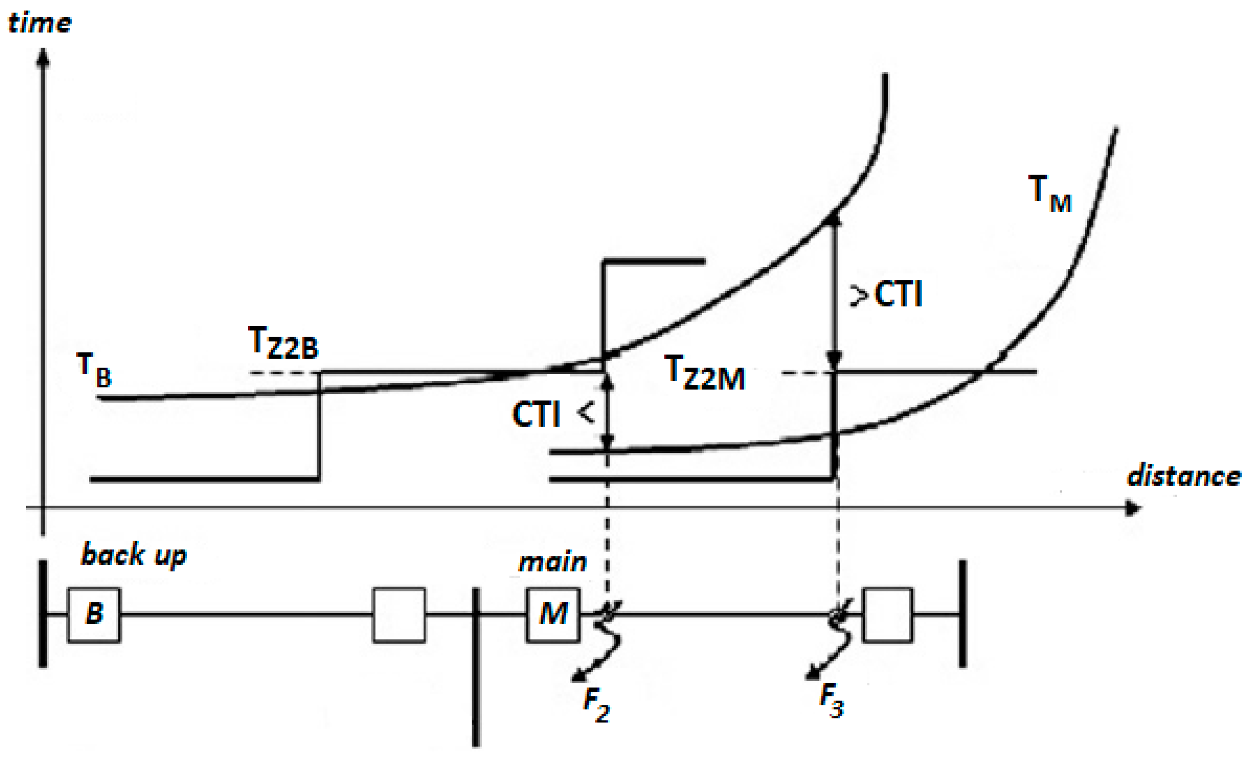
2. Coordination of Overcurrent and Distance Relays
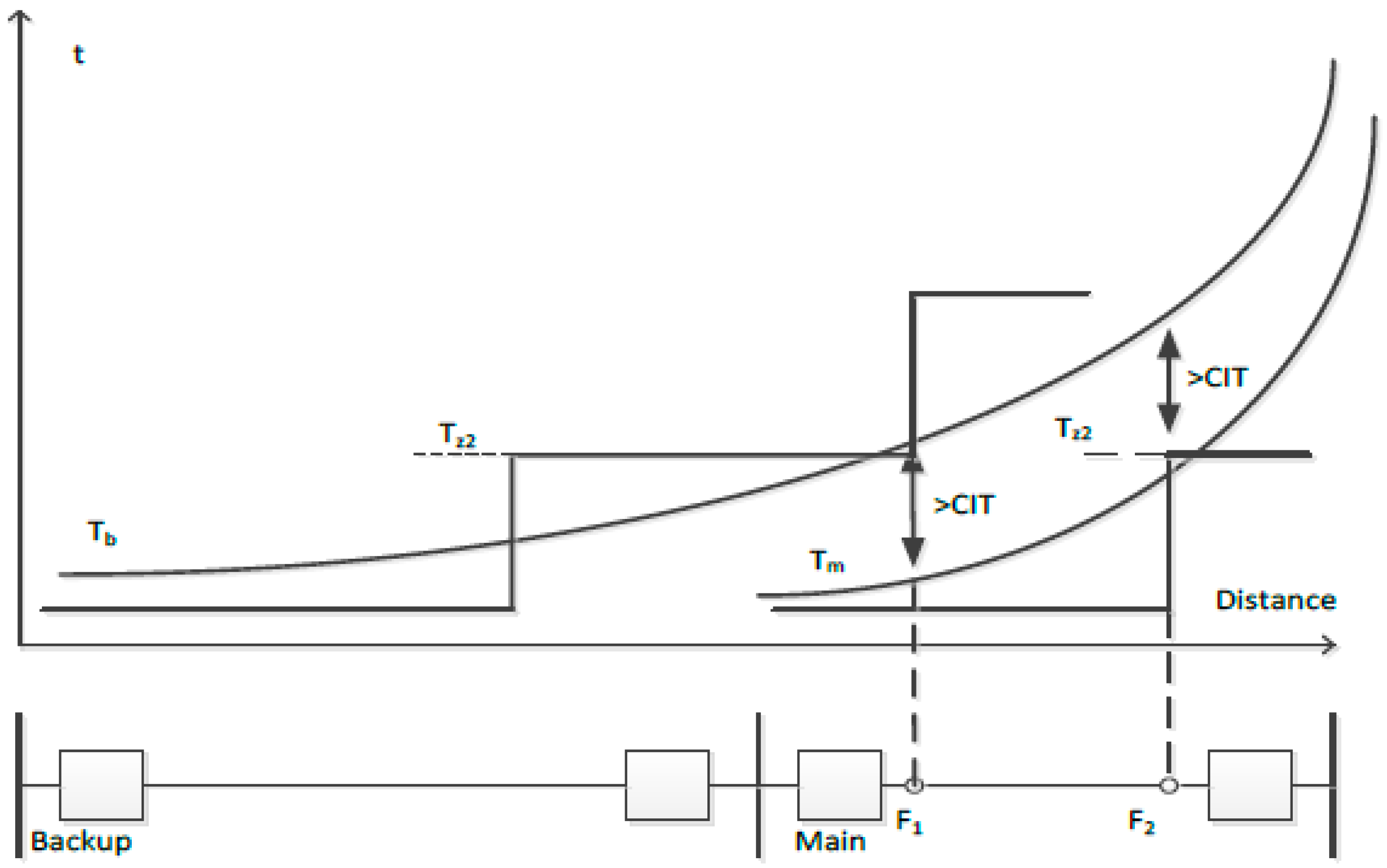
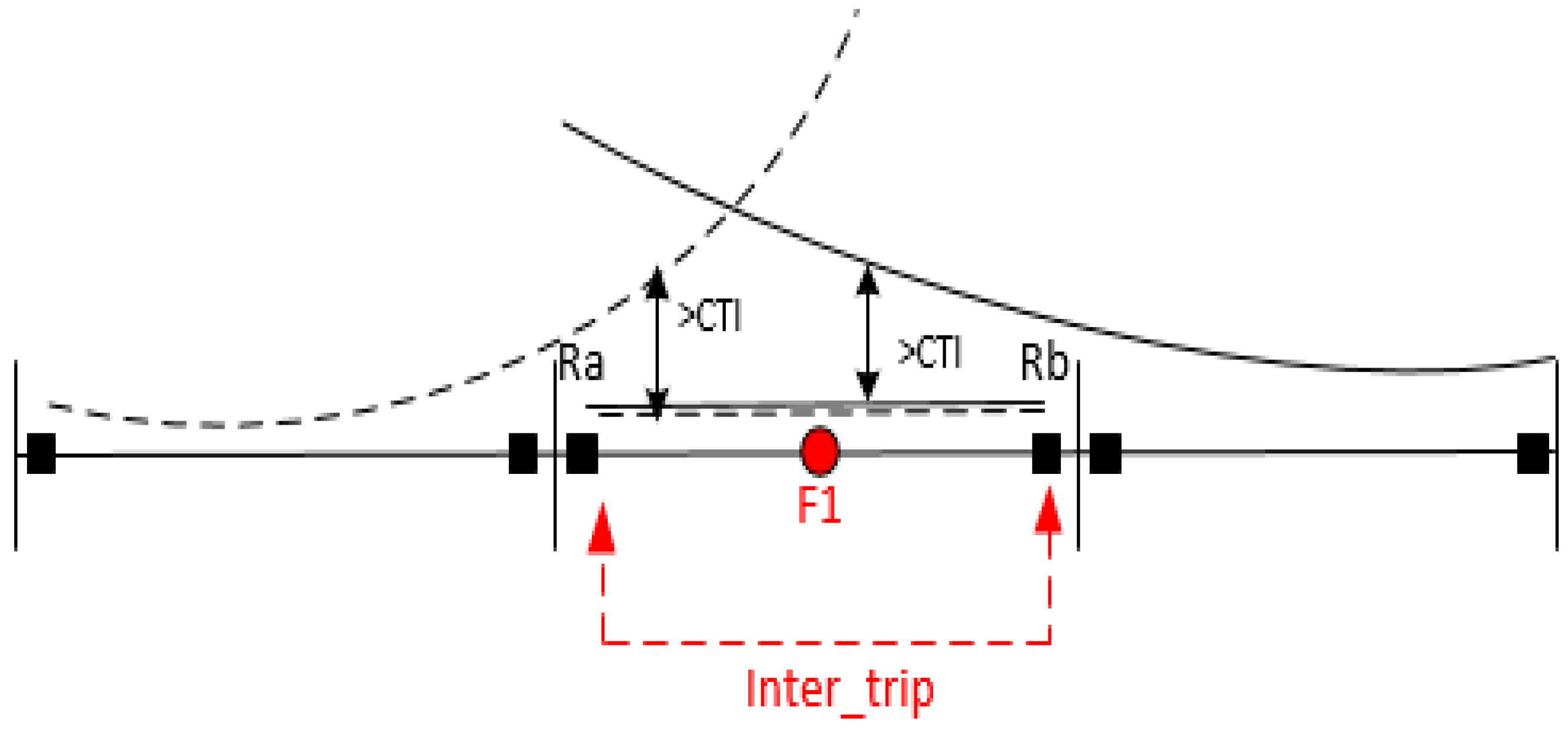
3. The Effect of a Communication Link on the Coordinated Performance of Overcurrent Relays
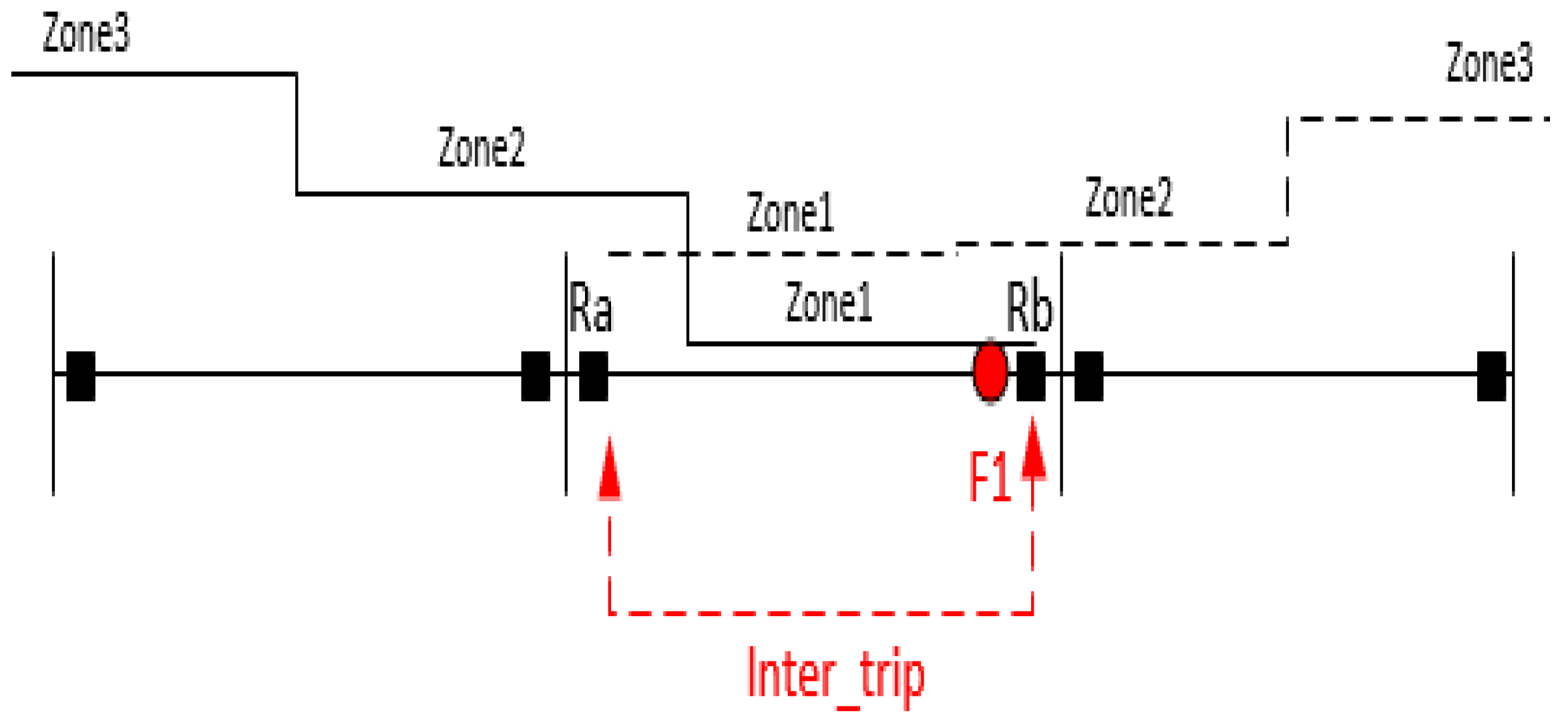
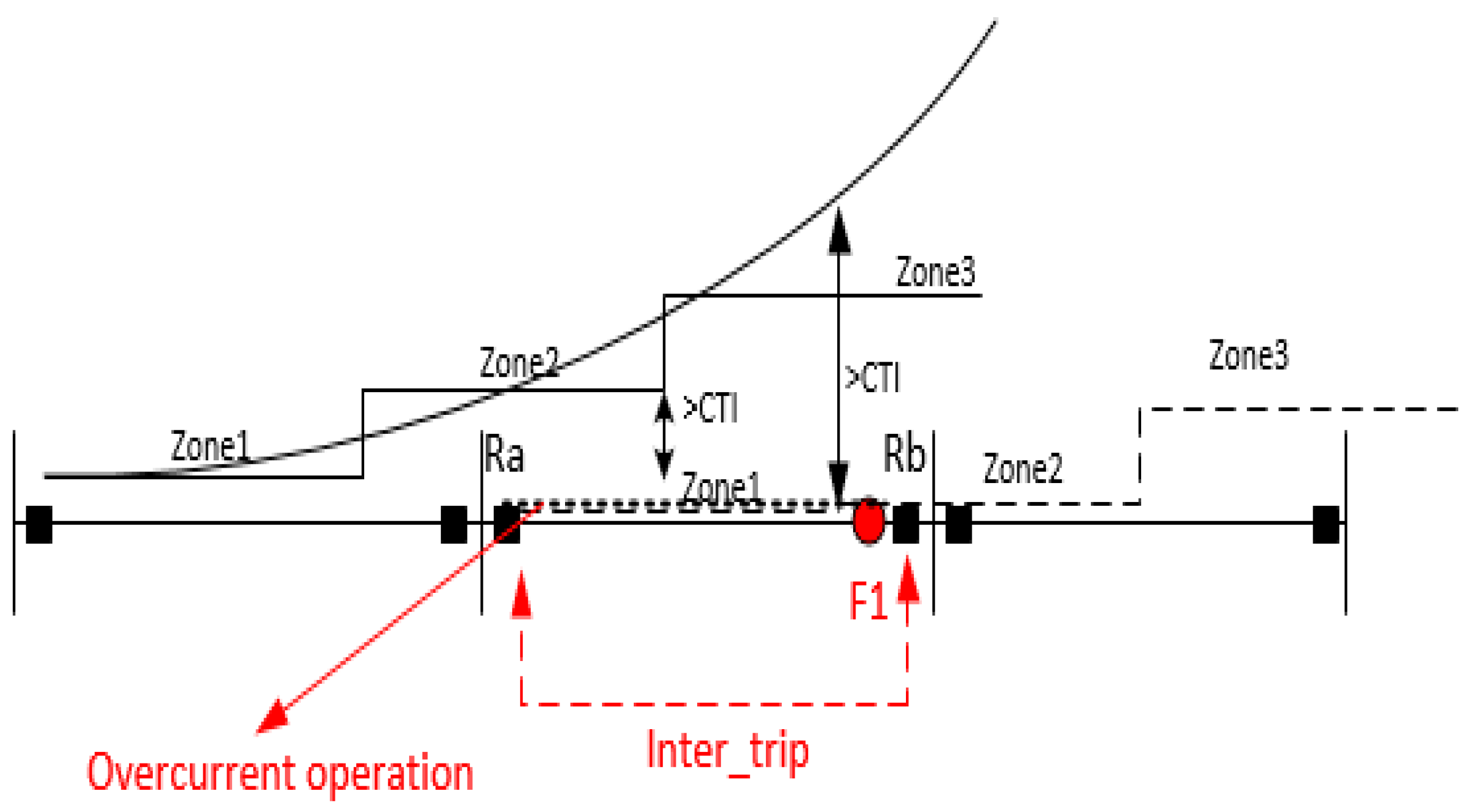
4. Using Communication Link in Distance Relays
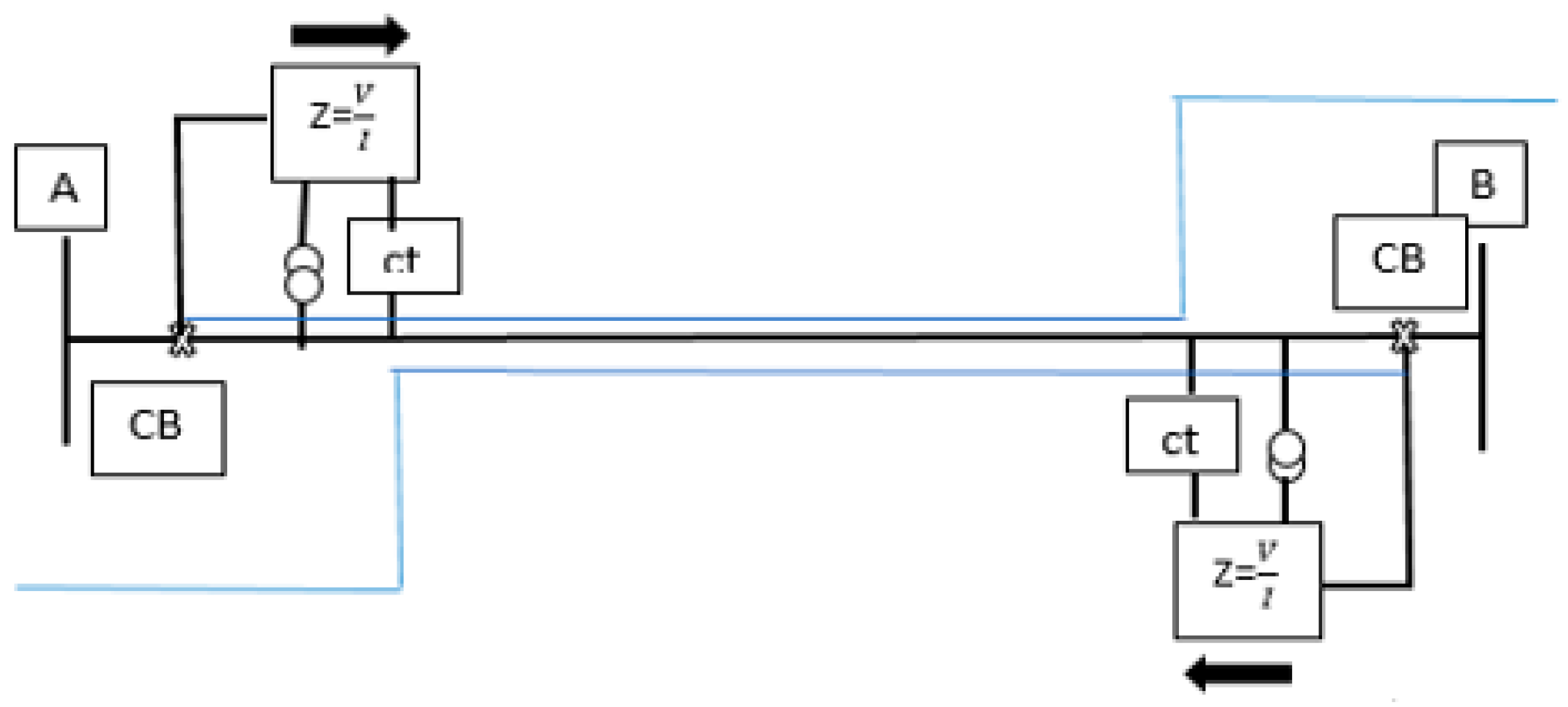
- Distance protection by directly receiving the key disconnection signal: In this so-called direct method, a signal is sent to the other relay by operating one of the relays on the sides of the line, and this relay also operates without any criteria or restrictions. In this way, according to the figure, for the occurrence of an error in the first zone of relay A, if this error is also in the second zone of relay B, a direct signal is sent to relay B to act instantly.
- Distance protection by the developed zone: In this design, when an error occurs in the first zone of relay A and the second zone of relay B, a signal is sent from relay A to relay B, which increases the range of the first zone of relay B. This increase will be an average of 130% of the line length.
- Distance protection by means of the permitted switch-off relay of the range-increasing type: In this range protection plan, the first zone of each relay is developed and usually covers between 120% and 150% of the line impedance. In this method, not only does the developed area cause the signal to be sent to the relay of the other side, but it is also a criterion for the performance of each relay.
- Distance protection by sending a lock command: In this method, each relay has a reverse zone in addition to the extended zone. If an error has occurred in the extended area of relay B and in the reverse area of relay A, a signal from the reverse area of relay A is sent to bus B and prevents its operation. In this method, the extended area of relay B has a delay, and until the signal sent from the reverse area of relay A arrives and the correct command is issued for the operation of relay B, the disconnection command will not be issued [2].
5. The Effect of Using a Communication Link on the Coordinated Performance of Distance Relays
6. The Proposed Method
- (1)
- Entry of basic information: At first, basic information such as network load values, line impedance, location of relays, optimization algorithm settings, etc., is entered into the algorithm.
- (2)
- Calculation of fault currents: To calculate the operation time of overcurrent relays and solve the proposed problem, two three-phase faults were created at the end of the first zone and the end of the second zone of each of the distance relays and the currents. The passage of relays is measured and stored. These calculations are repeated for all lines.
- (3)
- Creation of the initial population: In the genetic optimization algorithm, the candidate solutions for the problem are generated in the form of a chromosome containing the random variables of the problem. In the proposed problem, the structure of each chromosome is according to Figure 8. As you can see, the structure of each chromosome includes two parts. In the first part, the location of installation of communication links from to is determined, where R is the maximum number of links that can be installed in the network (this location is in terms of line number). In the second part, the operation time of the second zone of each of the distance relays is stored.
- (4)
- The calculation of the objective function and operation time of the overcurrent relays: If the setting of the current of the overcurrent relays is known (which is considered 1.5 times the maximum load current in this article), coordinating the overcurrent relays and the distance becomes a problem. This becomes linear programming whose objective function is to minimize the operation time of overcurrent relays. The objective function of the linear programming algorithm is given in relation (13).
- (5)
- Applying the communication link: As stated before, to apply the location of the communication link produced by the genetic algorithm, the constraints of relations (17)–(19) are replaced by the constraints (14)–(16) as well as the operation time of the second zone of the distance relay. It is variable and is included in the chromosome. If a communication link is also added to a line, the operation time of the relays on both sides of the line will change.
- (6)
- Evaluation of the objective function: The objective function also changes if the communication link is applied. In this case, the objective function equals the total operation time of the main and backup overcurrent relays, as well as the total operation time of the second zone of the distance relay. The objective function of the desired optimization problem is in the form of relation (20):
- (7)
- Sorting and choosing the best answer.
- (8)
- Generation of a new population based on a combination operator.
- (9)
- Generation of a new population based on the mutation operator.
- (10)
- Complying with the stop condition: Steps seven to nine of the optimization algorithms are executed in each repetition until the number of repetitions reaches the maximum value considered. Finally, the algorithm stops, and the optimal answer is shown. This answer will include the number and the best places to install communication links and the optimal settings of each of the overcurrent and distance relays.
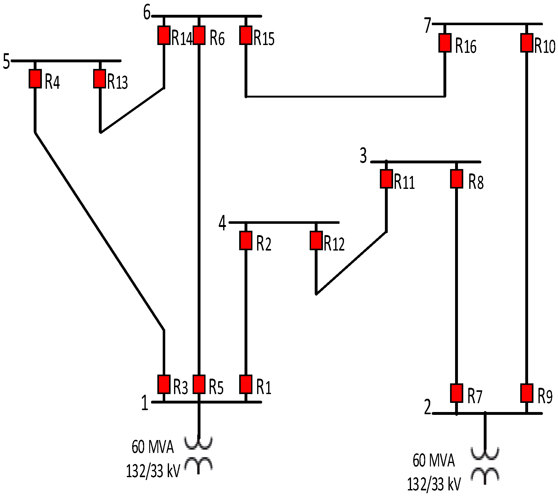
7. Study System and Result
8. Conclusions
Author Contributions
Funding
Data Availability Statement
Conflicts of Interest
References
- Horowitz, S.H.; Phadke, A.G.; Henville, C.F. Power System Relaying; John Wiley & Sons: Hoboken, NJ, USA, 2022. [Google Scholar]
- Liu, Y.; Gao, H.; Gao, W.; Peng, F. Development of a substation-area backup protective relay for smart substation. IEEE Trans. Smart Grid 2016, 8, 2544–2553. [Google Scholar] [CrossRef]
- Xu, S.; Ma, J.; Cao, L.; Hu, W.; Chen, L.; Lu, H.; Liu, B.; Dai, Z. Reliability evaluation of centralized protection system in smart substation considering impact of communication message. In Proceedings of the 2018 2nd IEEE Conference on Energy Internet and Energy System Integration (EI2), Beijing, China, 20–22 October 2018. [Google Scholar]
- Blackburn, J.L.; Domin, T.J. Protective Relaying: Principles and Applications; CRC press: Boca Raton, FL, USA, 2006. [Google Scholar]
- Ghotbi-Maleki, M.; Chabanloo, R.M.; Abyaneh, H.A.; Zamani, M. Considering transient short-circuit currents of wind farms in overcurrent relays coordination using binary linear programming. Int. J. Electr. Power Energy Syst. 2021, 131, 107086. [Google Scholar] [CrossRef]
- Jamali, S.; Borhani-Bahabadi, H. Protection method for radial distribution systems with DG using local voltage measurements. IEEE Trans. Power Deliv. 2018, 34, 651–660. [Google Scholar] [CrossRef]
- Bouchekara, H.R.E.H.; Zellagui, M.; Abido, M.A. Optimal coordination of directional overcurrent relays using a modified electromagnetic field optimization algorithm. Appl. Soft Comput. 2017, 54, 267–283. [Google Scholar] [CrossRef]
- Maleki, M.G.; Chabanloo, R.M.; Taheri, M.R. Mixed-integer linear programming method for coordination of overcurrent and distance relays incorporating overcurrent relays characteristic selection. Int. J. Electr. Power Energy Syst. 2019, 110, 246–257. [Google Scholar] [CrossRef]
- Yazdaninejadi, A.; Nazarpour, D.; Talavat, V. Coordination of mixed distance and directional overcurrent relays: Miscoordination elimination by utilizing dual characteristics for DOCR s. Int. Trans. Electr. Energy Syst. 2019, 29, e2762. [Google Scholar] [CrossRef]
- Rivas, A.E.L.; Pareja, L.A.G.; Abrão, T. Coordination of distance and directional overcurrent relays using an extended continuous domain ACO algorithm and an hybrid ACO algorithm. Electr. Power Syst. Res. 2019, 170, 259–272. [Google Scholar] [CrossRef]
- Ahmadi, S.A.; Karami, H.; Gharehpetian, B. Comprehensive coordination of combined directional overcurrent and distance relays considering miscoordination reduction. Int. J. Electr. Power Energy Syst. 2017, 92, 42–52. [Google Scholar] [CrossRef]
- El-Naily, N.; Saad, S.M.; Mohamed, F.A. Novel approach for optimum coordination of overcurrent relays to enhance microgrid earth fault protection scheme. Sustain. Cities Soc. 2020, 54, 102006. [Google Scholar] [CrossRef]
- Castillo, C.A.; Conde, A.; Fernandez, E. Mitigation of DOCR miscoordination through distance relays and non-standard overcurrent curves. Electr. Power Syst. Res. 2018, 163, 242–251. [Google Scholar] [CrossRef]
- Shabani, M.; Karimi, A. A robust approach for coordination of directional overcurrent relays in active radial and meshed distribution networks considering uncertainties. Int. Trans. Electr. Energy Syst. 2018, 28, e2532. [Google Scholar] [CrossRef]
- Sharaf, H.M.; Zeineldin, H.H.; Ibrahim, D.K.; Essam, E.L. A proposed coordination strategy for meshed distribution systems with DG considering user-defined characteristics of directional inverse time overcurrent relays. Int. J. Electr. Power Energy Syst. 2015, 65, 49–58. [Google Scholar] [CrossRef]
- Noghabi, A.S.; Sadeh, J.; Mashhadi, H.R. Parameter uncertainty in the optimal coordination of overcurrent relays. Int. Trans. Electr. Energy Syst. 2018, 28, e2563. [Google Scholar] [CrossRef]
- Singh, M.; Telukunta, V.; Srivani, S.G. Enhanced real time coordination of distance and user defined over current relays. Int. J. Electr. Power Energy Syst. 2018, 98, 430–441. [Google Scholar] [CrossRef]
- Bucolo, M.; Buscarino, A.; Famoso, C.; Fortuna, L. Chaos addresses energy in networks of electrical oscillators. IEEE Access 2021, 9, 153258–153265. [Google Scholar] [CrossRef]
- Abbasi, A.; Karegar, H.K.; Aghdam, T.S. Inter-trip links incorporated optimal protection coordination. Int. J. Electr. Comput. Eng. 2020, 10, 72. [Google Scholar] [CrossRef]


| Relay | ||
|---|---|---|
| 0.2118 | 0.8694 | |
| 0.2926 | 0.8573 | |
| 0.2519 | 0.8942 | |
| 0.2612 | 0.8493 | |
| 0.3622 | 0.9387 | |
| 0.2532 | 0.7343 | |
| 0.3926 | 0.8273 | |
| 0.2456 | 0.6716 | |
| 0.1342 | 0.8118 | |
| 0.3294 | 0.8794 | |
| 0.3395 | 0.7918 | |
| 0.4154 | 0.7294 | |
| 0.5183 | 0.9311 | |
| 0.2412 | 0.6936 | |
| 0.3616 | 0.8974 | |
| 0.2987 | 0.7483 |
| Main Relay | Main Relay Operation Time | Backup Relay | Backup Relay Operation Time | |
|---|---|---|---|---|
| L1 | R1 | 0.5184 | R4 | 0.7712 |
| R6 | 0.8956 | |||
| R2 | 0.5823 | R11 | 0.7901 | |
| L2 | R3 | 0.4912 | R2 | 0.9418 |
| R6 | 1.0311 | |||
| R4 | 0.4914 | R14 | 0.6891 | |
| L3 | R5 | 0.6246 | R2 | 0.8348 |
| R4 | 0.9089 | |||
| R6 | 0.5483 | R13 | 0.8295 | |
| R16 | 0.7542 | |||
| L4 | R7 | 0.6719 | R10 | 0.8845 |
| R8 | 0.5123 | R12 | 0.7594 | |
| L5 | R9 | 0.4510 | R8 | 0.7216 |
| R10 | 0.6901 | R15 | 1.1191 | |
| L6 | R11 | 0.5899 | R7 | 0.8112 |
| R12 | 0.6594 | R1 | 0.8649 | |
| L7 | R13 | 0.6821 | R3 | 0.8742 |
| R14 | 0.3984 | R5 | 0.8910 | |
| R16 | 0.8389 | |||
| L8 | R15 | 0.7164 | R5 | 0.9143 |
| R13 | 0.9143 | |||
| R16 | 0.5834 | R9 | 0.8612 |
| Main Relay | Main Relay Operation Time | Backup Relay | Backup Relay Operation Time | |
|---|---|---|---|---|
| L1 | R1 | 0.7245 | R4 | 1.0484 |
| R6 | 1.0484 | |||
| R2 | 0.7216 | R11 | 1.0812 | |
| L2 | R3 | 0.5821 | R2 | 1.4084 |
| R6 | 4.7542 | |||
| R4 | 0.5882 | R14 | 1.1015 | |
| L3 | R5 | 0.7423 | R2 | 1.1620 |
| R4 | 1.5812 | |||
| R6 | 0.5691 | R13 | 1.1623 | |
| R16 | 1.6283 | |||
| L4 | R7 | 0.8072 | R10 | 1.5423 |
| R8 | 0.5942 | R12 | 0.8549 | |
| L5 | R9 | 0.5126 | R8 | 1.0141 |
| R10 | 1.1129 | R15 | 1.0251 | |
| L6 | R11 | 0.6986 | R7 | 0.9816 |
| R12 | 0.7789 | R1 | 1.3453 | |
| L7 | R13 | 0.8105 | R3 | 1.5726 |
| R14 | 0.4694 | R5 | 1.5812 | |
| R16 | 2.1632 | |||
| L8 | R15 | 0.8794 | R5 | 1.5114 |
| R13 | 1.2728 | |||
| R16 | 0.7493 | R9 | 0.9489 |
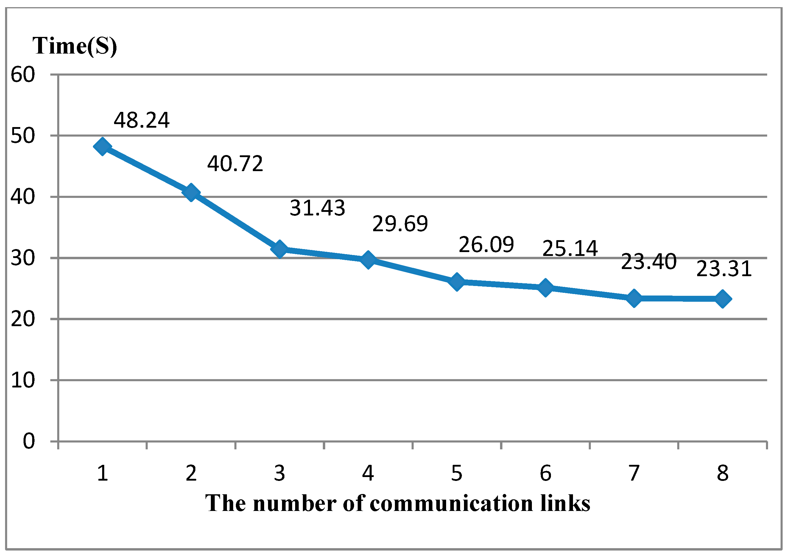
| The Value of the Objective Function | Optimal Link Location (Line Number) | Maximum Number of Communication Links |
|---|---|---|
| 48.24 | 6 | 1 |
| 40.72 | 5, 6 | 2 |
| 31.43 | 3, 6, 8 | 3 |
| 29.69 | 1, 3, 4, 8 | 4 |
| 26.09 | 1, 3, 4, 7, 8 | 5 |
| 25.14 | 1, 3, 4, 5, 7, 8 | 6 |
| 23.40 | 1, 2, 3, 5, 6, 7, 8 | 7 |
| 23.31 | 1, 2, 3, 4, 5, 6, 7, 8 | 8 |
Disclaimer/Publisher’s Note: The statements, opinions and data contained in all publications are solely those of the individual author(s) and contributor(s) and not of MDPI and/or the editor(s). MDPI and/or the editor(s) disclaim responsibility for any injury to people or property resulting from any ideas, methods, instructions or products referred to in the content. |
© 2023 by the authors. Licensee MDPI, Basel, Switzerland. This article is an open access article distributed under the terms and conditions of the Creative Commons Attribution (CC BY) license (https://creativecommons.org/licenses/by/4.0/).
Share and Cite
Azari, A.; Noghabi, A.S.; Zishan, F.; Montoya, O.D.; Molina-Cabrera, A. Evaluating the Effect of the Communication Link of the Relays on the Operation Time of the Protection System. Energies 2023, 16, 2692. https://doi.org/10.3390/en16062692
Azari A, Noghabi AS, Zishan F, Montoya OD, Molina-Cabrera A. Evaluating the Effect of the Communication Link of the Relays on the Operation Time of the Protection System. Energies. 2023; 16(6):2692. https://doi.org/10.3390/en16062692
Chicago/Turabian StyleAzari, Aliakbar, Abass Saberi Noghabi, Farhad Zishan, Oscar Danilo Montoya, and Alexander Molina-Cabrera. 2023. "Evaluating the Effect of the Communication Link of the Relays on the Operation Time of the Protection System" Energies 16, no. 6: 2692. https://doi.org/10.3390/en16062692
APA StyleAzari, A., Noghabi, A. S., Zishan, F., Montoya, O. D., & Molina-Cabrera, A. (2023). Evaluating the Effect of the Communication Link of the Relays on the Operation Time of the Protection System. Energies, 16(6), 2692. https://doi.org/10.3390/en16062692