Abstract
The rapid development of photovoltaic technology provides more possibilities for the efficient application of solar energy in buildings. This research proposed a phase change material (PCM) heat storage wall system with a “four-layer” structure. A performance test platform using low voltage DC was built to study the mechanism of electric thermal conversion of the graphene electrothermal film and the heat transfer characteristics of the “four-layer” structure. As shown in the experimental results, under the voltages of 24 V, 32 V and 42 V, (1) with the increase in voltage, the temperature of the electrothermal film increases, while its electrothermal conversion efficiency decreases from 85% to 75%; (2) during the heat storage process, because of its latent heat storage characteristics, the temperature of the PCM wallboard is 3~5 °C lower than that of the cement wallboard, but the effective heat storage increases by 59~65%; (3) during the heat release process, the effective heat release of the PCM wallboard increases by 41–78%, and the maximum heat storage and release efficiency is 98%; and (4) at 32 V, the PCM can completely change phase. The theoretical calorific value of the electrothermal film is equivalent to the hourly power generation of 1.45 m2 of photovoltaic modules. The results provide basic data for the integration of photovoltaic and phase change technology and their efficient application in buildings.
1. Introduction
Photovoltaic technology has become increasingly more developed [1,2,3] and its application costs have decreased year on year. It is now possible to efficiently apply solar photovoltaic technology in building energy systems. However, due to the low energy flow density, intermittency, instability and other characteristics of solar energy, the quality of photovoltaic power is low and it is difficult to absorb sunlight [4,5]. It is of great significance to study ways to improve the efficiency of photovoltaic power, especially the self-consumption mode of photovoltaic power.
Previous studies on the application of solar photovoltaic technology in building energy systems mostly used building integrated photovoltaic systems (BIPV) to provide electricity for buildings [6,7,8], or used photovoltaic module cooling systems (BIPVT) to realize the utilization of photovoltaic module waste heat in buildings [9,10,11].
The development of electrothermal film technology [12,13,14] provides the possibility for the application of solar photovoltaic technology. Xin Meng et al. [15] used 3D graphene-based composite materials to construct a film with high electrical and thermal conductivity. When the input voltage was 10 V, the film showed excellent electrical heating performance at 315 °C and a heating rate of 44.9 °C/s. Guoqin Leng et al. [16] proposed a new porous carbon fiber electrothermal material connected by the inorganic compound aluminum phosphate (CKFC), and combined it to prepare a CKFC/PA composite material. It could quickly raise the temperature to 45 °C within a safe voltage and delay the heat release. Deju Zhu et al. [17] developed an electric floor heating system with carbon fiber tape (CFT) embedded in cement mortar. It could quickly heat indoor air with a floor temperature rise rate of 1.83 °C/min and a heat flux of 16.31 W/m2 at a voltage of 24 V.
Phase change materials (PCMs) have become a highly researched and widely used material because they can store or release a large amount of latent heat in a very small temperature range. They are also indispensable functional materials for the efficient application of renewable energy. Barrio et al. [18] conducted a comparative experiment of floor radiant heating with NPG phase change materials and ordinary concrete in a thermostatic chamber. The results showed that floor radiant heating with phase change materials was more efficient at regulating temperature. Barbara Larwa et al. [19] conducted an experimental and numerical study on a circulating floor radiant heating system integrated with phase change materials. The results showed that the heat flux of the floor could be effectively enhanced by arranging the phase change materials under the heating pipes and using wet sand as the floor filling material. Guan Yong et al. [20] designed a phase change heat storage wall composed of a phase change material layer, a middle bearing layer and an outer insulation layer, and studied the effect of the wall on improving the thermal environment of a solar greenhouse. The experimental results showed that the surface temperature of the north wall of the experimental greenhouse increased on average from 2.1 to 4.3 °C at night. The average soil temperature of the plough layer increased from 0.5 to 1.4 °C. Additionally, the average temperature of the indoor environment increased by 1.6~2.1 °C. The experimental results of an active-passive solar phase change heat storage ventilation wall system proposed by Ling Haoshu et al. [21,22,23,24] showed that the heat storage capacity of the wall increased by 35.27~47.89% and the heat release capacity increased by 49.93~60.21%.
In order to conveniently evaluate the thermal performance of a building structure containing PCMs, Yuan Zhang et al. [25] established two mathematical evaluation parameter models by using the finite difference method. The thermal performance database of the building envelope filled with PCMs covered 2401 different configurations. The average relative error of the model was 7.7%. While modeling with EnergyPlus, Fan Feng et al. [26] considered the influence of the thermal hysteresis effect in the melting and solidification process of PCMs on their calculation results. The study improved the calculation accuracy of the model. Maria T. et al. [27] simulated and evaluated an in-floor solar-assisted heating system based on a PCM. The PCM was laid under the heating water pipe, the solar collector area was set to 20 m2, and the storage tank volume was set to 1 m3, which was the best design scheme of the system. The design increased the indoor temperature by about 0.8 °C. Xiaoqin Sun et al. [28] applied distributed photovoltaics to provide power for the air conditioning system of a building. An insulation board encapsulated with phase change materials was embedded into the building wall to reduce the energy consumption of the air conditioning. The experimental results showed that the use of 5.2 vol% PCM in a building with an area of 6.25 m2 reduced the carbon emissions by 11.58 kg.
Previous studies have either focused on the phase change thermal storage of the combination of a solar energy system and the building system, or on the phase change thermal storage of the constant electricity photovoltaic power supply for building envelopes. However, there are some problems, such as the large loss of surplus electricity and the high economic cost of constant electricity photovoltaic systems.
Therefore, this study proposes the design of a photovoltaic electricity–heat direct-driven composite phase change thermal storage heating wall. The system converts low-voltage DC generated by a photovoltaic system into heat energy through an electrothermal film. Additionally, PCMs realize low-cost and high-efficiency self-consumption of photovoltaic power. Combined with the previous research results and experimental research methods, this work deeply studied and identified the electro-thermal conversion characteristics of a graphene, flexible, low voltage, electrothermal film. These included the surface temperature of the heating fibers of the electrothermal film, the change in the electro-thermal conversion efficiency and the change in key influencing factors. This paper analyzed and established the heat transfer mechanism and variation law of a composite phase change heat storage wallboard, including the heat transfer characteristics of a PCM and its influence on the temperature field and the heat storage/release performance of the composite phase change heat storage wallboard. This research provides the basic data and a design method reference for the efficient application of solar photovoltaic electro-thermal phase change thermal storage walls in building energy systems.
2. Solar Photovoltaic Electric-Thermal Wall
2.1. Wall Construction Concept
A solar greenhouse is a semi-enclosed agricultural building composed of walls (north, east and west walls), a rear roof, a front roof, soil and ground [29]. Studies [20] have shown that one-third of the solar energy entering the greenhouse through the front roof will be projected to the north wall of the greenhouse. The area of the north wall is much larger than that of the east and west gables, about five times as much. Therefore, in previous studies, our research group has organically integrated solar air heat collection technology and phase change heat storage technology, proposing a solar active-passive “three-layer” structure composite phase change thermal storage wall system [30,31] (Figure 1). The wall was built with a phase change material layer on the inner surface, an air channel and a building block brick layer in the middle and a heat insulation layer on the outer surface. The structure maximizes the heat collection and heat storage functions of the north wall, and in particular plays the role of a “radiator” at night. Thereby, the purpose of active-passive heat storage of the wall body of the solar greenhouse in winter and improvement of the guarantee of a thermal environment of the solar greenhouse are achieved.
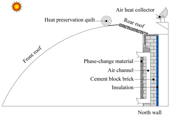
Figure 1.
Structure of the solar active-passive “three-layer” composite phase change heat storage wall.
A large number of practical application results have shown that the multi-curved double-tube air collector [30] developed by our research group has a high heat collection efficiency. However, the higher the outlet air temperature of the collector, the greater the progressive temperature drop. The actual effective heat collection efficiency of the collector was not at a high level. In addition, due to the structural characteristics of the air collector and the low air density and specific heat, the air flow handled by the collector was also very limited. The actual heat collection was too small. Moreover, most collectors are used in winter. The utilization rate and the economical profits of the equipment are not high [32,33].
In Figure 2, if the power generation efficiency of monocrystalline silicon solar photovoltaic modules used in Beijing is calculated as 17%, a single photovoltaic module (2094 mm × 1038 mm) provides 1.1 kWh a day. This is promising for applications in solar greenhouses. Therefore, this study proposed a design concept of a “four-layer” structure composite phase change thermal storage heating wall based on a solar photovoltaic electricity-heat system, which would be applied to solar greenhouses (Figure 3). The solar photovoltaic module replaced the air heat collection system in Figure 1. Electrothermal film replaced the air channel in Figure 1. During the heating period in winter, the low-voltage direct current generated by the photovoltaic system is transmitted to the electrothermal film. The film converts electric energy into heat energy and stores it in the composite phase change heat storage wall body with the function of a heat reservoir or a heat switch. At night, the wall heats the solar greenhouse by means of convection and radiation heat exchange. In other seasons, photovoltaic power is used to supply power for agricultural production machinery. It achieves the purpose of self-consumption of photovoltaic power for self-use and efficient utilization of photovoltaic equipment throughout the year. At present, the PV modules produced in China are about 2 RMB/W (RMB 1 ≈ USD 0.15). The electric heating film is about 80 RMB/m2. The phase change material is about 27 RMB/kg. Additionally, the cement is about 5 RMB/kg. The comprehensive cost is basically the same as that of the solar active-passive “three-layer” structure composite phase change heat storage wall in Figure 1. However, the photovoltaic system can be used throughout the year, while the heat collection system has only 30% utilization rate throughout the year.
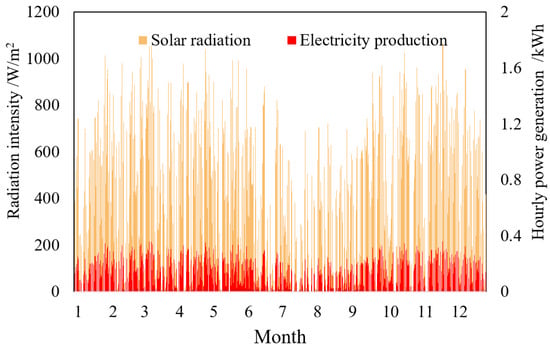
Figure 2.
Calculation of power generation of monocrystalline silicon solar PV modules (Beijing, China).
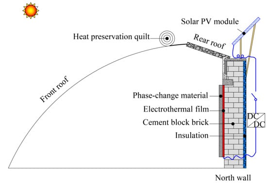
Figure 3.
“Four-layer” structure composite phase change heat storage heating wall of a solar photovoltaic electric-thermal system.
2.2. Wall Thermal Performance Evaluation Index
- (1)
- Wall layer temperature
The wall temperature is one of the key parameters that reflects the thermal performance and heating capacity of the wall [34]. Figure 4 shows the experimental results of the inner surface temperature of the active-passive “three-layer” structure composite phase change heat storage wall from November to December 2022 in a solar greenhouse (Beijing, China).
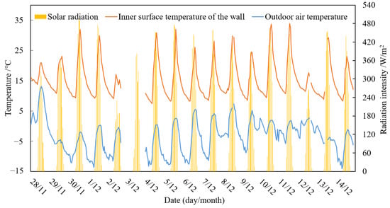
Figure 4.
The temperature of the inner surface of the wall in the experimental solar greenhouse.
- (2)
- Wall heat storage/release
The heat storage/release of the composite phase change heat storage wall is divided into sensible heat and latent heat. For phase change materials, the concept of equivalent specific heat [35] is used to evaluate their latent heat storage capacity. Therefore, the storage/release of sensible heat and latent heat of the wall can be calculated according to Formula (1).
where Qd is the heat storage/release (J/m3); 𝜌 is the density (kg/m3); c is the specific heat (including the equivalent specific heat of the phase change material) (J/kg °C); 𝜏start is the initial time of heat storage or release (s); 𝜏end is the termination time of heat storage or release (s); and V is the wall volume (m3).
- (3)
- Wall heat storage/release efficiency
The ratio of heat release to heat storage of the wall is recorded as the heat storage and release efficiency. It is used to evaluate the effective utilization rate of heat storage of the wall.
- (4)
- Electrothermal conversion efficiency of electrothermal film
The ratio of the effective calorific value to the theoretical calorific value of the electrothermal film is called the electrothermal conversion efficiency (η) of the electrothermal film. It is used to evaluate the electric heating performance of the electric heating film. Obviously, the larger the value is, the stronger the effective heating ability of the electrothermal film. That is,
where Qact is the effective calorific value of the electrothermal film (kJ), which refers to the actual calorific value after deducting the loss of the electrothermal film due to its own material characteristics, and P is the theoretical calorific value of the electrothermal film (calculated according to Formula (3)) (kJ).
where U is the input voltage of the film (Volts) and I is the input current (Amperes).
3. Construction of Test Platform
3.1. Electrothermal Performance Test Platform of Electrothermal Film
3.1.1. Experimental Overview
In this experiment, a graphene, low-voltage, flexible, electrothermal film (referred to as an electrothermal film), which is relatively well-established, low cost and widely applied in China, was selected as the experimental object. The electrothermal film consists of a copper current-carrying strip, graphene heating fibers and a polyester net. The distance between the two current-carrying strips is 750 mm, the diameter of the heating fibers is 0.68 mm and the space between the heating fibers is filled with a polyester mesh at a distance of 20 mm (Figure 5). The electrical characteristics of the electrothermal film follow Ohm’s law. Each graphene heating fiber is both a resistance element and a heating element.
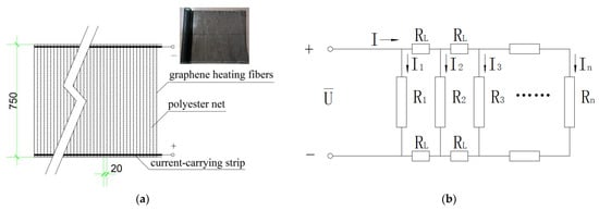
Figure 5.
The structure (a) and principle (b) of the electrothermal film.
3.1.2. Experimental Conditions
In order to grasp the electrothermal conversion characteristics of the electrothermal film for solar photovoltaic power, an electrothermal performance test platform (Figure 6) was built in this study. It could investigate the electrothermal conversion characteristics of a single heating fiber and multiple heating fibers in parallel.
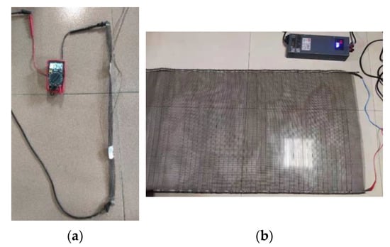
Figure 6.
Real view of experimental system for determining the electrothermal conversion characteristics of the electrothermal film. (a) Single heating fiber. (b) Multiple heating fibers.
Figure 7 shows the volt–ampere characteristics of the solar PV module. When the output voltage is less than 42 V, the output current of the photovoltaic module is relatively stable and is hardly affected by the change in the output voltage. The output power increases linearly with the increase in the output voltage. On the contrary, the output current and power both decrease sharply and approach zero when the voltage is 50 V. The working voltage and current of the PV module vary with the load resistance. If the load resistance value is selected to maximize the product of the output voltage and current, the maximum output power (Pm) can be obtained. The corresponding operating voltage and current are the optimum operating voltage (Um) and the optimum operating current (Im), respectively [36]. The results show that the optimum operating voltage of the solar cell is about 42 V when the solar radiation reaches 200~600 W/m2.
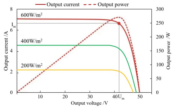
Figure 7.
Volt–ampere characteristic curve of the solar PV module.
Considering the volt–ampere characteristics of the solar photovoltaic module and the safety of the electrothermal film, the input voltage of the electrothermal film is 45 V, the maximum safe length is 2 m and the power per unit area is 750 W/m2. The relevant experimental conditions are shown in Table 1. The experimental process was as follows: (1) The input voltage for a single heating fiber was changed every 4 min. The surface temperature of the heating fiber was studied under different voltage and power conditions. (2) The input voltage of the electrothermal film was changed according to the different length of the electrothermal film (the number of parallel heating fibers). The surface temperature and electrothermal conversion characteristics were studied under different voltage and power conditions.

Table 1.
Experimental conditions of electrothermal film.
A Testo 872 infrared imager (Testo Instrument International Trading Co., Ltd., Shanghai, China, measurement range: −20~280 °C, accuracy: ±2 °C, thermal sensitivity: <0.12 °C) was used to measure the surface temperature of the heating fiber, and the data acquisition interval was 10 min. The voltage was measured with a multimeter (Delixi Electric Co., Ltd., Leqing, China, current measurement range: 0~10 A, accuracy: ± 0.1 mA, resolution: 0.1 mA), and the initial voltage was set as 5 V with measurement increments of 5 V.
3.2. Test Platform for Thermal Performance of Wallboard
3.2.1. Experimental Overview
The composite phase change thermal storage heating wallboard (referred to as the PCM wallboard) used in this experiment was mainly composed of an XPS extruded polystyrene insulation board (layer I) (50 mm), cement (layer II) (50 mm), the electrothermal film (layer III), cement (layer IV) (10 mm) and a PCM (layer V) (50 mm). Layer V (50 mm) of the cement heating wallboard (referred to as the cement wallboard) was a cement layer and the others were the same as above (Figure 8a). The model and specification of the electrothermal film were the same as those in Section 4.3.1, and the length was 1 m. The location of each experimental measuring point is shown in Figure 8.
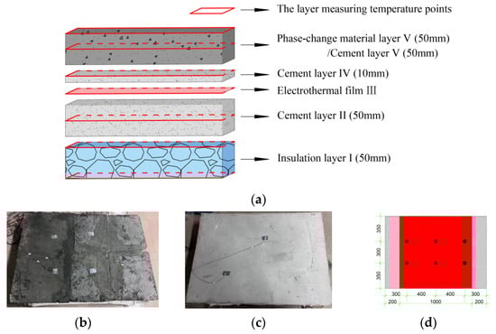
Figure 8.
Layout of experimental wallboard and measuring points. (a) Phase change/cement wallboard. (b) Picture of the PCM wallboard. (c) Picture of the cement wallboard. (d) Layout plan of temperature measuring points.
The PCM in the experimental wallboard is a GH-20 paraffin-based composite shape-stabilized PCM developed by our research group [34,35]. The PCM was prepared by using a self-adaptive packaging process method. It was prepared by taking paraffin as the heat storage material, crosslinked high-density polyethylene as the main supporting material and expanded graphite and SBS together as the encapsulating materials. Among these, the content of paraffin, as the main heat storage agent, is as high as 78%. The phase change range is 17.5~27.5 °C, the phase change latent heat is 128.1 kJ/kg and the leakage rate is less than 5%. The curve of equivalent specific heat and temperature obtained from the DSC curve of the material is shown in Figure 9. The physical parameters of each material layer of the wallboard test piece are shown in Table 2.
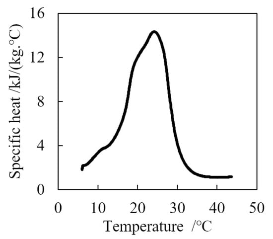
Figure 9.
Equivalent specific heat of PCM.
Table 2.
Material physical parameters of each layer of the experimental wallboard.
3.2.2. Experimental Conditions
The temperature measuring points of the two experimental wallboards are arranged as shown in Figure 8. Forty-two temperature measuring points were arranged on each layer of each experimental part, and six measuring points were arranged on each layer. The temperature sensor was a copper-constantan T-type thermocouple (produced by Chengdu Liangsen Electric Appliance Co., Ltd., Chengdu, China, measuring range: −40~200 °C, accuracy: ±0.5 °C, resolution: 0.1 °C). Temperature data processing was performed by an Agilent DAQ970A inspection instrument (produced by Shanghai Agilent Technology Co., Ltd., Shanghai, China, measurement range: −100~400 °C, accuracy: ±0.1 °C, resolution: 0.1 °C). Temperature data were collected and recorded at a frequency of 10 s.
Figure 10 is a schematic diagram of the experimental system, which is composed of a low-voltage DC heating wallboard, a multimeter, an AC/DC converter, a temperature sensor, an inspection instrument and a computer.
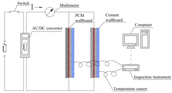
Figure 10.
Schematic diagram of wallboard thermal performance test system.
In view of the fact that our research group has carried out a large number of initial studies on the thermal performance of solar active-passive “three-layer” structure composite phase change heat storage walls, this study focuses on the influence of the electrothermal characteristics of the graphene low-voltage flexible electrothermal film as an “internal heat source” on the storage/release characteristics of the composite phase change heat storage wallboard. In addition, in order to reduce the influence of the temperature fluctuation of the external environment, the experiment was carried out indoors where the ambient temperature is relatively stable.
According to Figure 7, considering the classification of low voltage in China, 24 V, 32 V and 42 V low-voltage DC voltages were selected as the experimental voltages in this experiment.
The experiment was divided into the heat storage process and the heat release process. In the heat storage process, the wall was continuously powered for 8 h under the input voltages of 24 V, 32 V and 42 V. The heat release test was started immediately after the heat storage test, and continuous natural cooling was carried out for 16 h.
4. Experimental Results and Analysis
4.1. Electrothermal Characteristics of Electrothermal Film
4.1.1. Single Heating Fiber
The experimental results in Figure 11 show that under the experimental conditions, as the input voltage increases, the corresponding input power increases and the surface temperature of a single heating fiber also increases in the same way. The difference is that when the surface temperature of the heating fiber is lower than 60 °C, its resistance is relatively stable at about 143 Ω. When the surface temperature of the exothermic fiber is above 60 °C, its resistance decreases at a rate of 0.17 Ω/°C with the increase in temperature. The figure also shows that when the surface temperature of the heating fiber is lower than 60 °C, the resistance stability is better.
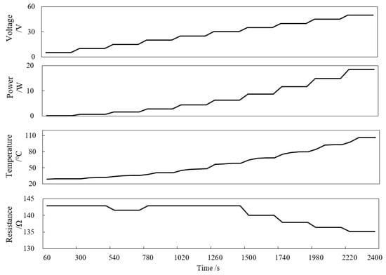
Figure 11.
Electrothermal characteristics of single heating fiber.
4.1.2. Multiple Heating Fibers
Figure 12 shows the electrothermal characteristics of multiple parallel heating fibers with lengths of 0.5 m, 1.0 m, 1.5 m and 2 m under the experimental conditions. According to Ohm’s law, as the number of single heating fibers in parallel increases, the corresponding total resistance will decrease. That is to say, with the increase in the length of the electrothermal film, the number of parallel single heating fibers increases and the total resistance decreases.
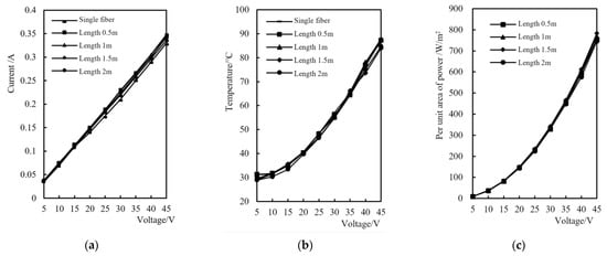
Figure 12.
Electrothermal characteristics of multiple heating fibers in parallel. (a) Voltage vs. current, (b) voltage vs. power per unit area and (c) voltage vs. surface temperature.
On the whole, the electro-thermal characteristics of multiple heating fibers in parallel are similar to those of a single heating fiber. When the length of the electrothermal film was changed from 0.5 m to 2 m, the current of the electrothermal film with a longer length under the same input voltage was larger (Figure 12a). However, the power per unit area of the electrothermal film hardly changes as the length increases (Figure 12b). This is because when the distance between the heating fibers of the electrothermal film is fixed, the number of parallel heating fibers per unit area of the electrothermal film is fixed. Consequently, the corresponding resistance value is also fixed. Therefore, the variation in the surface temperature of the electrothermal film per unit area with the increase in the input voltage is basically the same (Figure 12c).
4.2. Temperature Characteristics of Wallboard
4.2.1. Heat Storage Process
Figure 13 shows a comparison of the temperature variation characteristics between the PCM layer V of the PCM wallboard and the corresponding cement layer V of the cement wallboard under different input voltages. The experiment was carried out at an ambient temperature of about 16 ± 1 °C.
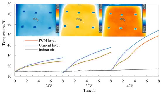
Figure 13.
Temperature comparison test results of layer V between two wallboards (heat storage process).
Affected by the thermal storage characteristics of phase change materials, no matter how the input voltage changes, the temperature of the PCM layer is always lower than that of the corresponding layer in the cement wallboard. When the input voltages are 24 V, 32 V and 42 V, the temperatures of the PCM wallboard are about 3 °C, 6 °C and 8 °C lower than that of the cement wallboard. With an 8 h heat storage process, the temperature of PCM layer V is about 3~5 °C lower than that of the cement wallboard.
In addition, with the increase in the input voltage, the heating rate of the wallboard also increases, but then gradually decreases with time. In the phase change temperature range, the heating rate of PCM layer is always lower than that of the same layer in the cement wallboard. When the temperature exceeds the phase change temperature range, the heating rate of the V layer is higher than that of the cement wallboard, and then gradually tends to be the same.
4.2.2. Heat Release Process
After the end of the heat storage process, the heat release process was started, which was also carried out at an ambient temperature of about 16 ± 1 °C (Figure 14).
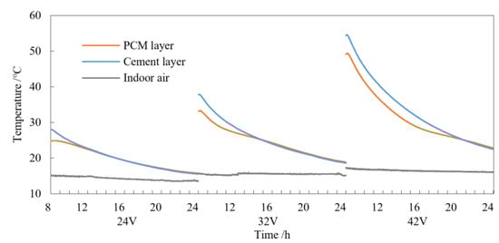
Figure 14.
Temperature comparison of layer V between the two wallboards (exothermic process).
In the initial stage of heat release, the temperature of the PCM layer of the phase change wallboard is about 3~5 °C lower than that of the same layer in the cement wallboard. With the progress of the exothermic process, especially in the phase change temperature range, the temperature drop rate of the PCM layer is lower than that of the cement wallboard. The higher the input voltage under the heat storage process, the higher the difference between the temperature drop rates. The difference between the PCM with both sensible and latent heat storage/release properties and the cement material with only sensible heat storage/release properties is also shown.
4.3. Heat Storage/Release Characteristics of Wallboard
4.3.1. Heat Storage
Figure 15 shows the variation in the heat storage capacity of the PCM wallboard and the cement wallboard with time under the experimental conditions of 24 V, 32 V and 42 V input voltage. According to the experimental analysis results in Figure 4, this study focuses on the situation where the surface temperature of the two experimental wallboards is below 35 °C. The heat storage capacity of each material layer of the wallboard can be calculated according to Formula (1).
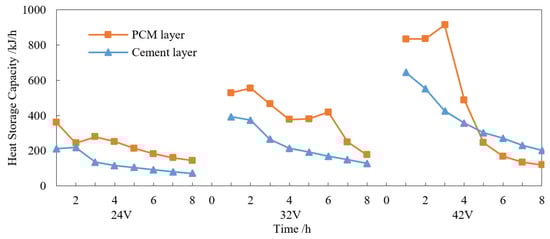
Figure 15.
Comparative experimental results of heat storage capacity of layer V between the two wallboards.
With the increase in input voltage, the heat storage of the two experimental wallboards increases. The difference is that in the phase change temperature range, the effective heat storage of the PCM layer is about 169%, 173% and 185% higher than that of the same layer in the cement wallboard. When the temperature is higher than the phase change temperature (27.5~35 °C), the effective heat storage is about 31% and 37% higher than the cement wallboard at the input voltages of 32 V and 42 V, respectively (the highest temperature of the two experimental wallboards corresponding to the input voltage of 24 V can only reach 25 °C). When the temperature exceeds 35 °C, the PCM mainly stores sensible heat, and its heat storage capacity is not as good as that of the same layer in the cement wallboard.
Figure 16 reflects the trends in sensible heat storage, latent heat storage, heat exchange with the surrounding environment, and calorific value difference (the difference between the theoretical calorific value of the electrothermal film and its effective calorific power) of the two experimental wallboards with time under different input voltages. The sensible heat and latent heat storage were calculated according to the Formula (1). The amount of heat exchange with the ambient environment was calculated according to Formula (4). The sum of the sensible heat storage, latent heat storage and heat exchange with the surrounding environment can be regarded as the effective heating value of the electric heating film. The difference in the heating value of the electric heating film can be calculated by combining Formula (3).
where ΔQ is the heat exchange quantity between the outer surface of the wallboard and the surrounding environment (W); h is the comprehensive convective heat transfer coefficient between the environment and the wallboard (W/(m2·°C)); 𝐹 is the external surface area of the wallboard (m); 𝑡 is the surface temperature of the wallboard (°C); and 𝑡f is the ambient air temperature (°C).
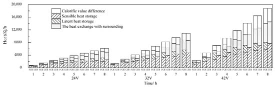
Figure 16.
Variation in heat storage of the wallboards with time.
When the input voltage is 24 V (Figure 16), with the progress of the heat storage process, the temperature of the two experimental wallboards and the difference with the environment increase, and the heat storage and heat exchange with the surroundings also increase. The difference is that the weight of the PCM is only 8% of the whole wallboard, but its latent heat storage accounts for 34% of the total heat storage. The temperature of the material layer of the cement wallboard is relatively high; therefore, the heat exchange with the surrounding environment is 13% higher than that of the PCM wallboard. At the end of the heat storage process, the total heat storage of the PCM wallboard is 3135 kJ, which is 59% higher than that of cement wallboard under the same temperature conditions. The experimental results (Figure 16b) when the input voltages are 32 V and 42 V are basically similar to those when the input voltage is 24 V.
According to Figure 16 and Formula (2), it can be calculated that the electrothermal conversion efficiencies of the PCM wallboard electrothermal film are 85%, 80% and 75%, respectively, under the experimental conditions of input voltages of 24 V, 32 V and 42 V. Obviously, an excessive voltage will restrict the improvement in the electrothermal conversion efficiency of the electrothermal film.
4.3.2. Heat Release
According to the analysis method in Section 4.3.1, the trends in heat release of the PCM wallboard and the cement wallboard with time under the corresponding heat storage process can be obtained (Figure 17 and Figure 18).
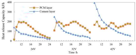
Figure 17.
Heat release comparison of layer V between the two wallboards.
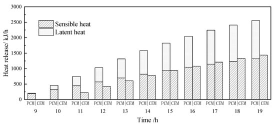
Figure 18.
Variation in heat release of the wallboards with time.
The effective heat release of the PCM layer is about 155%, 188% and 216% higher than that of the same layer in the cement wallboard in the phase change temperature range (Figure 17). The effective heat release of the PCM layer is about 39% (32 V) and 31% (42 V) higher than that of the cement layer in the range of 27.5~35 °C.
In the phase change temperature range, the latent heat release of the PCM wallboard accounts for about 48% of the total heat release. The total heat release (2558 kJ) of the PCM wallboard (9th~19th h) is 78% higher than that of the cement wallboard (11th~19th h). The thermal efficiency of storage and discharge is as high as 97%.
In the same way, the heat release processes at input voltages of 32 V and 42 V during the heat storage process follow similar rules. The latent heat release of the PCM wallboard accounts for 52% and 49% of its total heat release, and the total heat release of the PCM wallboard (3193 kJ and 1863 kJ) is 80% and 84% higher than that of the cement wallboard. The latent heat release of the PCM wallboard accounts for 18% and 21% of the total heat release, and the total heat releases of the PCM wallboard (1352 kJ and 1911 kJ) are 32% and 17% higher than those of the cement wallboard. The exothermic efficiencies of the PCM wallboard are about 85% and 77%.
5. Discussion
Considering the application scenarios and the conditions of the solar photovoltaic electric-thermal system with a “three-layer” structure composite phase change heat storage heating wall, the output voltage of the photovoltaic system is ≥32 V. This is beneficial for optimum heat storage of the phase change wall during periods of sunshine in winter.
According to the analysis results in Section 4.3.1, the electrothermal conversion efficiency of the electrothermal film is about 80%. The corresponding theoretical calorific value and effective calorific value are 1365 kJ/(m2·h) and 1100 kJ/(m2·h), respectively, at a voltage of 32 V. Its theoretical calorific value is equivalent to the hourly power generation of 1.45 m2 (0.73 pieces) of monocrystalline silicon solar photovoltaic modules (Figure 2). The results provide an important basic data reference for the subsequent matching modes of photovoltaic systems and electrothermal films, as well as the optimization of the design of “four-layer” structure composite phase change thermal storage heating walls.
6. Conclusions
In this study, the experimental results of a graphene, low-voltage, flexible, electrothermal film and composite phase change thermal storage heating wallboard show that:
- When the input voltages of the electrothermal film are 24 V, 32 V and 42 V, the surface temperature of the heating fiber of the electrothermal film increases exponentially with the increase in voltage. When the surface temperature is lower than 60 °C, the resistance stability is better. The electrothermal conversion efficiency decreases with the increase in input voltage, which is about 85~75%.
- During thermal storage, when the input voltages are 24 V, 32 V and 42 V, because of the thermal storage characteristics of the PCM wallboard, the temperature of each layer is relatively low; 3~5 °C lower than that of the cement wallboard on average. In the phase change temperature range, the effective heat storage of the PCM layer is about 169%, 173% and 185% higher than that of the same layer of the cement wallboard. At a temperature of 35 °C or below (including the phase change temperature range), the effective heat storages of the PCM wallboard are 59%, 58% and 65% higher than that of the cement wallboard, respectively.
- During heat release, the effective heat release of the PCM wallboard increases by 78%, 63% and 41%, respectively, compared with that of the cement wallboard in the temperature range of 35 °C and below (including the phase change temperature range) under the three different voltages. The corresponding heat storage and release efficiencies are 98%, 85% and 77%, respectively.
On the basis of the above research, further research will be carried out on the dynamic output characteristics of photovoltaic systems, as well as the photoelectric thermal coupling mechanism and its influence on the phase change of the wallboard system. This study will provide applications and design methods for the efficient application of this technology in energy systems of agricultural buildings.
Supplementary Materials
The following supporting information can be downloaded at: https://www.mdpi.com/article/10.3390/en16062595/s1, File S1: Experimental data.
Author Contributions
Conceptualization, C.C. and X.M.; methodology, C.C. and X.M.; validation, X.M., H.F. and G.L.; formal analysis, X.M. and G.L.; investigation, H.F. and Y.J.; resources, H.F. and Y.J.; data curation, G.L.; writing—original draft preparation, X.M.; writing—review and editing, F.H.; visualization, X.M. and H.F.; supervision, F.H.; proofreading, X.M., C.C., H.F., G.L., Y.J. and F.H.; project administration, C.C.; funding acquisition, C.C. All authors have read and agreed to the published version of the manuscript.
Funding
This research was funded by major science and technology project of Beijing, No. Z211100004621002.
Data Availability Statement
The authors confirm that the data supporting the findings of this study are available within the article and the Supplementary Materials.
Conflicts of Interest
The authors declare no conflict of interest.
References
- Tomar, V.; Tsang, E.K.W.; Li, D.H.W. Performance analysis of a prototype solar photovoltaic/wickless heat pipe embedded aluminum curtain wall-heat pump water heating system. Energy Convers. Manag. 2022, 258, 115559. [Google Scholar] [CrossRef]
- Kim, A.A.; Reed, D.A.; Choe, Y.; Wang, S.; Recart, C. New Building Cladding System Using Independent Tilted BIPV Panels with Battery Storage Capability. Sustainability 2019, 11, 5546. [Google Scholar] [CrossRef]
- Akshayveer; Singh, A.P.; Kumar, A.; Singh, O.P. Effect of natural convection and thermal storage system on the electrical and thermal performance of a hybrid PV-T/PCM systems. Mater. Today Proc. 2021, 39, 1899–1904. [Google Scholar] [CrossRef]
- Mora, A.; Verma, P.; Kumar, S. Electrical conductivity of CNT/polymer composites: 3D printing, measurements and modeling. Compos. Part B-Eng. 2020, 183, 107600. [Google Scholar] [CrossRef]
- Cabeza, L.F.; Sole, A.; Barreneche, C. Review on sorption materials and technologies for heat pumps and thermal energy storage. Renew. Energy 2017, 110, 3–39. [Google Scholar] [CrossRef]
- Chae, Y.T.; Kim, J.; Park, H.; Shin, B. Building energy performance evaluation of building integrated photovoltaic (BIPV) window with semi-transparent solar cells. Appl. Energy 2014, 129, 217–227. [Google Scholar] [CrossRef]
- Benemann, J.; Chehab, O.; Schaar-Gabriel, E. Building-integrated PV modules. Sol. Energy Mater. Sol. Cells 2001, 67, 345–354. [Google Scholar] [CrossRef]
- Jayathissa, P.; Luzzatto, M.; Schmidli, J.; Hofer, J.; Nagy, Z.; Schlueter, A. Optimising building net energy demand with dynamic BIPV shading. Appl. Energy 2017, 202, 726–735. [Google Scholar] [CrossRef]
- Curpek, J.; Cekon, M. Climate response of a BiPV facade system enhanced with latent PCM-based thermal energy storage. Renew. Energy 2020, 152, 368–384. [Google Scholar] [CrossRef]
- Jahangir, M.H.; Razavi, S.M.E.; Kasaeian, A.; Sarrafha, H. Comparative study on thermal performance of an air based photovoltaic/thermal system integrated with different phase change materials. Sol. Energy 2020, 208, 1078–1090. [Google Scholar] [CrossRef]
- Huang, M.J. The effect of using two PCMs on the thermal regulation performance of BIPV systems. Sol. Energy Mater. Sol. Cells 2011, 95, 957–963. [Google Scholar] [CrossRef]
- Jeong, Y.G.; An, J.-E. UV-cured epoxy/graphene nanocomposite films: Preparation, structure and electric heating performance. Polym. Int. 2014, 63, 1895–1901. [Google Scholar] [CrossRef]
- An, J.-E.; Jeong, Y.G. Structure and electric heating performance of graphene/epoxy composite films. Eur. Polym. J. 2013, 49, 1322–1330. [Google Scholar] [CrossRef]
- Lu, P.; Cheng, F.; Ou, Y.; Lin, M.; Su, L.; Chen, S.; Yao, X.; Liu, D. A flexible and transparent thin film heater based on a carbon fiber/heat-resistant cellulose composite. Compos. Sci. Technol. 2017, 153, 1–6. [Google Scholar] [CrossRef]
- Meng, X.; Chen, T.; Li, Y.; Liu, S.; Pan, H.; Ma, Y.; Chen, Z.; Zhang, Y.; Zhu, S. Assembly of carbon nanodots in graphene-based composite for flexible electro-thermal heater with ultrahigh efficiency. Nano Res. 2019, 12, 2498–2508. [Google Scholar] [CrossRef]
- Leng, G.; Duan, S.; Liu, X.; Lin, F.; Yang, Y.; Min, X.; Mi, R.; Wu, X.; Liu, Y.; Fang, M.; et al. Porous biological carbon fiber foam combined by aluminum phosphate for enhancing electric heating and electric thermal storage performance. J. Energy Storage 2022, 55, 105815. [Google Scholar] [CrossRef]
- Zhu, D.J.; Liu, S.; Rahman, M.Z.; Guo, S.C.; Yang, Z.H. Experimental and numerical study on a new floor heating system using carbon fiber tape embedded in cement mortar. J. Build. Eng. 2022, 56, 104699. [Google Scholar] [CrossRef]
- Barrio, M.; Font, J.; Lopez, D.O.; Muntasell, J.; Tamarit, J.L. Floor Radiant System With Heat-Storage by a Solid-phase Transition Material. Sol. Energy Mater. Sol. Cells 1992, 27, 127–133. [Google Scholar] [CrossRef]
- Larwa, B.; Cesari, S.; Bottarelli, M. Study on thermal performance of a PCM enhanced hydronic radiant floor heating system. Energy 2021, 225, 120245. [Google Scholar] [CrossRef]
- Guan, Y.; Chen, C.; Han, Y.; Ling, H.; Yan, Q. Experimental and modelling analysis of a three-layer wall with phase change thermal storage in a Chinese solar greenhouse. J. Build. Phys. 2015, 38, 548–559. [Google Scholar] [CrossRef]
- Ling, H.S.; Chen, C.; Guan, Y.; Wei, S.; Chen, Z.G.; Li, N. Active heat storage characteristics of active-passive triple wall with phase change material. Sol. Energy 2014, 110, 276–285. [Google Scholar] [CrossRef]
- Ling, H.; Chen, C.; Wei, S.; Guan, Y.; Ma, C.; Xie, G.; Li, N.; Chen, Z. Effect of phase change materials on indoor thermal environment under different weather conditions and over a long time. Appl. Energy 2015, 140, 329–337. [Google Scholar] [CrossRef]
- Chen, C.; Ling, H.; Zhai, Z.; Li, Y.; Yang, F.; Han, F.; Wei, S. Thermal performance of an active-passive ventilation wall with phase change material in solar greenhouses. Appl. Energy 2018, 216, 602–612. [Google Scholar] [CrossRef]
- Ling, H.; Wang, L.; Chen, C.; Wang, Y.; Chen, H. Effect of thermophysical properties correlation of phase change material on numerical modelling of agricultural building. Appl. Therm. Eng. 2019, 157, 113579. [Google Scholar] [CrossRef]
- Zhang, Y.; Jiang, W.; Song, J.; Xu, L.; Li, S.; Hu, L. A parametric model on thermal evaluation of building envelopes containing phase change material. Appl. Energy 2023, 331, 120471. [Google Scholar] [CrossRef]
- Feng, F.; Fu, Y.; Yang, Z.; O′Neill, Z. Enhancement of phase change material hysteresis model: A case study of modeling building envelope in EnergyPlus. Energy Build. 2022, 276, 112511. [Google Scholar] [CrossRef]
- Plytaria, M.T.; Tzivanidis, C.; Bellos, E.; Antonopoulos, K.A. Parametric analysis and optimization of an underfloor solar assisted heating system with phase change materials. Therm. Sci. Eng. Prog. 2019, 10, 59–72. [Google Scholar] [CrossRef]
- Sun, X.; Lin, Y.; Zhu, Z.; Li, J. Optimized design of a distributed photovoltaic system in a building with phase change materials. Appl. Energy 2022, 306, 118010. [Google Scholar] [CrossRef]
- Chen, C.; Li, Y.; Li, N.; Wei, S.; Yang, F.; Ling, H.; Yu, N.; Han, F. A computational model to determine the optimal orientation for solar greenhouses located at different latitudes in China. Sol. Energy 2018, 165, 19–26. [Google Scholar] [CrossRef]
- Chen, C.; Han, F.; Mahkamov, K.; Wei, S.; Ma, X.; Ling, H.; Zhao, C. Numerical and experimental study of laboratory and full-scale prototypes of the novel solar multi-surface air collector with double-receiver tubes integrated into a greenhouse heating system. Sol. Energy 2020, 202, 86–103. [Google Scholar] [CrossRef]
- Han, F.T.; Chen, C.; Hu, Q.L.; He, Y.P.; Wei, S.; Li, C.Y. Modeling method of an active-passive ventilation wall with latent heat storage for evaluating its thermal properties in the solar greenhouse. Energy Build. 2021, 238, 110840. [Google Scholar] [CrossRef]
- Acuna, A.; Velazquez, N.; Sauceda, D.; Aguilar, A. Modeling, Construction, and Experimentation of a Compound Parabolic Concentrator with a Concentric Tube as the Absorber. J. Energy Eng. 2017, 143, 04016059. [Google Scholar] [CrossRef]
- Ural, T. Experimental performance assessment of a new flat-plate solar air collector having textile fabric as absorber using energy and exergy analyses. Energy 2019, 188, 116116. [Google Scholar] [CrossRef]
- Yu, N.; Chen, C.; Mahkamov, K.; Han, F.; Zhao, C.; Lin, J.; Jiang, L.; Li, Y. Selection of a phase change material and its thickness for application in walls of buildings for solar-assisted steam curing of precast concrete. Renew. Energy 2020, 150, 808–820. [Google Scholar] [CrossRef]
- Ling, H.; Chen, C.; Qin, H.; Wei, S.; Lin, J.; Li, N.; Zhang, M.; Yu, N.; Li, Y. Indicators evaluating thermal inertia performance of envelops with phase change material. Energy Build. 2016, 122, 175–184. [Google Scholar] [CrossRef]
- Xue, C.; Qian, B.; Jiang, X.; Zhou, C. Solar Photovoltaic Module Technology; Science Press: Beijing, China, 2019. [Google Scholar]
Disclaimer/Publisher’s Note: The statements, opinions and data contained in all publications are solely those of the individual author(s) and contributor(s) and not of MDPI and/or the editor(s). MDPI and/or the editor(s) disclaim responsibility for any injury to people or property resulting from any ideas, methods, instructions or products referred to in the content. |
© 2023 by the authors. Licensee MDPI, Basel, Switzerland. This article is an open access article distributed under the terms and conditions of the Creative Commons Attribution (CC BY) license (https://creativecommons.org/licenses/by/4.0/).